

Page 1

24" BANDSAW
MODEL G7211/G7212
INSTRUCTION MANUAL
COPYRIGHT ©1992 BY GRIZZLY INDUSTRIAL, INC.
WARNING: NO PORTION OF THIS MANUAL MAY BE REPRODUCED IN ANY SHAPE
OR FORM WITHOUT THE WRITTEN APPROVAL OF GRIZZLY INDUSTRIAL, INC.
REVISED AUGUST, 2000 PRINTED IN TAIWAN
DISCONTINUED MACHINE MANUAL DISCLAIMER
THE INFORMATION IN THIS MANUAL REPRESENTS THE LAST CONFIGURATION OF THE MACHINE BEFORE IT WAS DISCONTINUED. MACHINE CONFIG-
URATIONS MAY HAVE CHANGED AS PRODUCT IMPROVEMENTS WERE INCORPORATED. IF YOU OWN AN EARLIER VERSION OF THE MACHINE, THIS
MANUAL MAY NOT EXACTLY DEPICT YOUR MACHINE . CONTACT CUSTOMER SERVICE IF YOU HAVE ANY QUESTIONS ABOUT DIFFERENCES. PREVI-
OUS VERSIONS ARE NOT AVAILABLE ONLINE.
Page 2

WARNING
Some dust created by power sanding, sawing, grinding, drilling, and other construction activities contains
chemicals known to the State of California to cause
cancer, birth defects or other reproductive harm.
Some examples of these chemicals are:
• Lead from lead-based paints.
• Crystalline silica from bricks, cement, and
other masonry products.
• Arsenic and chromium from chemically treated
lumber.
Your risk from these exposures varies, depending on
how often you do this type of work. To reduce your
exposure to these chemicals: work in a well ventilated
area, and work with approved safety equipment, such
as those dust masks that are specially designed to filter out microscopic particles.
Page 3

G7211/7212 24" Bandsaw -1-
Table Of Contents
PAGE
1. SAFETY
SAFETY RULES FOR POWER TOOLS ............................................................2-3
ADDITIONAL SAFETY INSTRUCTIONS FOR BANDSAWS ................................4
2. CIRCUIT REQUIREMENTS
220V OPERATION ................................................................................................5
EXTENSION CORDS ............................................................................................5
WIRING DIAGRAM ................................................................................................5
3-PHASE OPERATION ..........................................................................................6
3. INTRODUCTION
COMMENTARY......................................................................................................7
UNPACKING ..........................................................................................................8
PARTS INVENTORY..............................................................................................8
CLEAN UP..............................................................................................................9
SITE CONSIDERATIONS ......................................................................................9
4. ASSEMBLY
FENCE..................................................................................................................10
5. ADJUSTMENTS
TRACKING ..........................................................................................................11
TENSION..............................................................................................................11
WHEEL ALIGNMENT ..........................................................................................12
UPPER GUIDES ............................................................................................12-13
LOWER GUIDES..................................................................................................13
POSITIVE TABLE STOP......................................................................................14
6. OPERATIONS
PRE-RUN CHECK................................................................................................15
BANDSAW BLADES ............................................................................................15
CHANGING BLADES ..........................................................................................16
CHANGING SPEEDS ..........................................................................................17
RIPPING ..............................................................................................................18
STACKED CUTS..................................................................................................18
CUTTING CURVES..............................................................................................19
RESAWING ..........................................................................................................19
7. MAINTENANCE
TABLE ..................................................................................................................20
V-BELTS ..............................................................................................................20
LUBRICATION......................................................................................................21
MISCELLANEOUS ..............................................................................................21
8. CLOSURE..................................................................................................................22
MACHINE DATA................................................................................................................23
PARTS BREAKDOWN AND PARTS LISTS ................................................................24-27
WIRING DIAGRAMS ....................................................................................................28-29
WARRANTY AND RETURNS ..........................................................................................30
Page 4
-2-
G7211/7212 24" Bandsaw
Safety Instructions For Power Tools
SECTION 1: SAFETY
5. KEEP CHILDREN AND VISITORS
AWAY. All children and visitors should be
kept a safe distance from work area.
6. MAKE WORK SHOP CHILD PROOF with
padlocks, master switches, or by removing
starter keys.
7. DON’T FORCE TOOL. It will do the job
better and safer at the rate for which it was
designed.
8. USE RIGHT TOOL. Don’t force tool or
attachment to do a job for which it was not
designed.
1. KEEP GUARDS IN PLACE and in working
order.
2. REMOVE ADJUSTING KEYS AND
WRENCHES. Form habit of checking to
see that keys and adjusting wrenches are
removed from tool before turning on.
3. KEEP WORK AREA CLEAN. Cluttered
areas and benches invite accidents.
4. DON’T USE IN DANGEROUS ENVIRONMENT. Don’t use power tools in damp or
wet locations, or where any flammable or
noxious fumes may exist. Keep work area
well lighted.
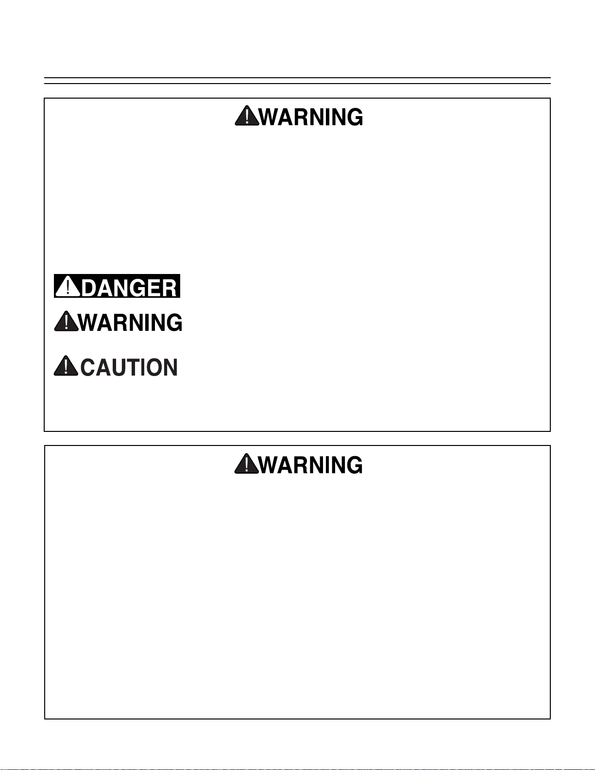
For Your Own Safety Read Instruction
Manual Before Operating This Equipment
Indicates an imminently hazardous situation which, if not avoided,
WILL result in death or serious injury.
Indicates a potentially hazardous situation which, if not avoided,
COULD result in death or serious injury.
Indicates a potentially hazardous situation which, if not avoided,
MAY result in minor or moderate injury. It may also be used to alert
against unsafe practices.
This symbol is used to alert the user to useful information about
proper operation of the equipment.
The purpose of safety symbols is to attract your attention to possible hazardous conditions. This
manual uses a series of symbols and signal words which are intended to convey the level of
importance of the safety messages. The progression of symbols is described below. Remember
that safety messages by themselves do not eliminate danger and are not a substitute for proper
accident prevention measures.
NOTICE
Page 5
G7211/7212 24" Bandsaw -3-
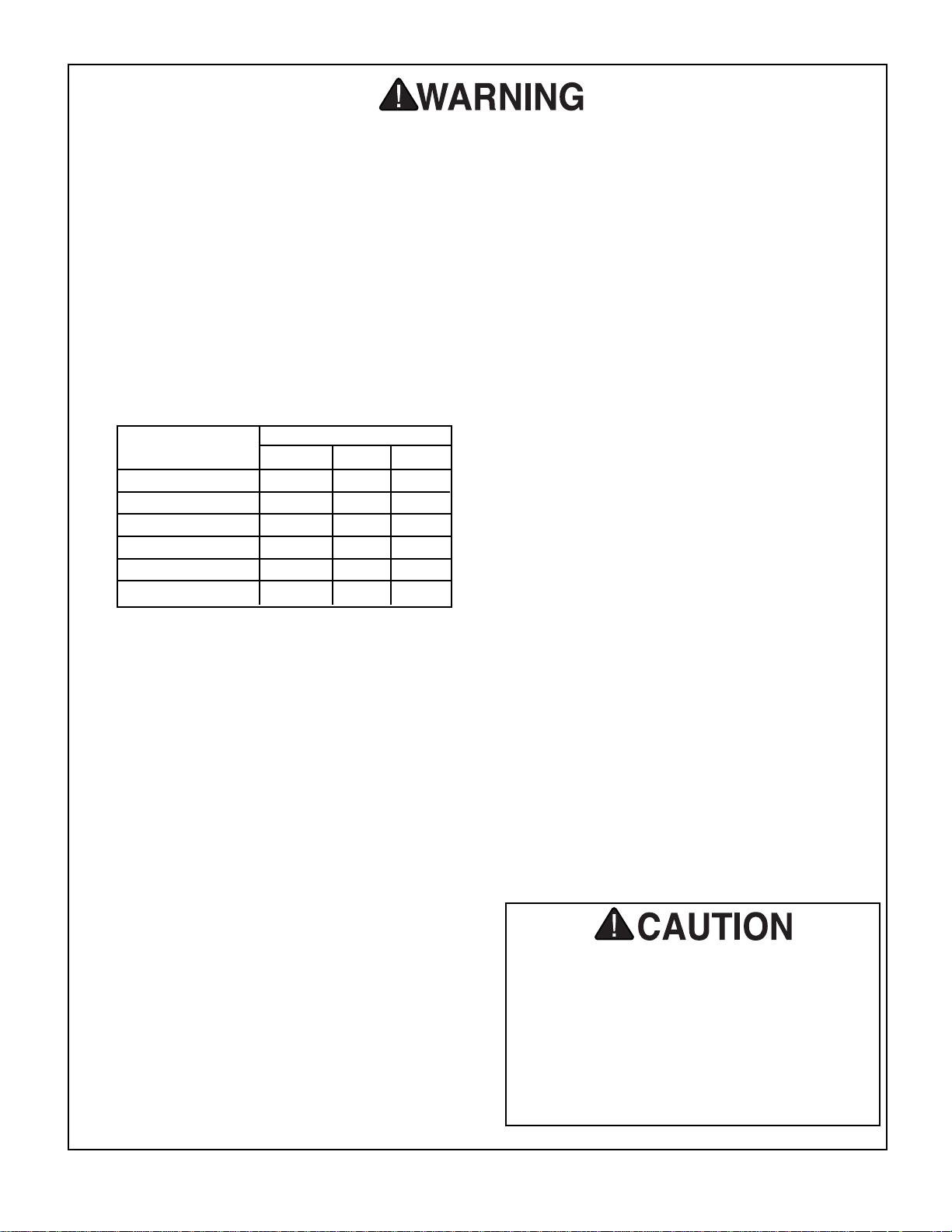
9. USE PROPER EXTENSION CORD. Make
sure your extension cord is in good condition. Conductor size should be in accordance with the chart below. The amperage
rating should be listed on the motor or tool
nameplate. An undersized cord will cause
a drop in line voltage resulting in loss of
power and overheating. Your extension
cord must also contain a ground wire and
plug pin. Always repair or replace extension cords if they become damaged.
Minimum Gauge for Extension Cords
10. WEAR PROPER APPAREL. Do not wear
loose clothing, gloves, neckties, rings,
bracelets, or other jewelry which may get
caught in moving parts. Non-slip footwear
is recommended. Wear protective hair covering to contain long hair.
11. ALWAYS USE SAFETY GLASSES. Also
use face or dust mask if cutting operation is
dusty. Everyday eyeglasses only have impact
resistant lenses, they are NOT safety glasses.
12. SECURE WORK. Use clamps or a vise to hold
work when practical. It’s safer than using your
hand and frees both hands to operate tool.
13. DON’T OVERREACH. Keep proper foot-
ing and balance at all times.
14. MAINTAIN TOOLS WITH CARE. Keep
tools sharp and clean for best and safest
performance. Follow instructions for lubricating and changing accessories.
15. USE RECOMMENDED ACCESSORIES.
Consult the owner’s manual for recommended accessories. The use of improper
accessories may cause risk of injury.
LENGTH
AMP RATING 25ft 50ft 100ft
0-6 18 16 16
7-10 18 16 14
11-12 16 16 14
13-16 14 12 12
17-20 12 12 10
21-30 10 10 No
Safety Instructions For Power Tools
16. REDUCE THE RISK OF UNINTENTIONAL STARTING. On machines with mag-
netic contact starting switches there is a
risk of starting if the machine is bumped or
jarred. Always disconnect from power
source before adjusting or servicing. Make
sure switch is in OFF position before reconnecting.
17. MANY WOODWORKING TOOLS CAN
“KICKBACK” THE WORKPIECE toward
the operator if not handled properly. Know
what conditions can create “kickback” and
know how to avoid them. Read the manual
accompanying the machine thoroughly.
18. CHECK DAMAGED PARTS. Before fur-
ther use of the tool, a guard or other part
that is damaged should be carefully
checked to determine that it will operate
properly and perform its intended function.
Check for alignment of moving parts, binding of moving parts, breakage of parts,
mounting, and any other conditions that
may affect its operation. A guard or other
part that is damaged should be properly
repaired or replaced.
19. NEVER LEAVE TOOL RUNNING UNATTENDED. TURN POWER OFF. Don’t
leave tool until it comes to a complete stop.
20. NEVER OPERATE A MACHINE WHEN
TIRED, OR UNDER THE INFLUENCE OF
DRUGS OR ALCOHOL. Full mental alert-
ness is required at all times when running
a machine.
No list of safety guidelines can be complete. Every shop environment is different.
Always consider safety first, as it applies to
your individual working conditions. Use
this and other machinery with caution and
respect. Failure to do so could result in
serious personal injury, damage to equipment or poor work results.
Page 6
-4-
G7211/7212 24" Bandsaw
Additional Safety Instructions For Bandsaws
No list of safety guidelines can be complete. Every shop environment is different.
Always consider safety first, as it applies to
your individual working conditions. Use
this and other machinery with caution and
respect. Failure to do so could result in
serious personal injury, damage to equipment or poor work results.
7. ALWAYS FEED STOCK EVENLY AND
SMOOTHLY. Do not force or twist blade
while cutting, especially when sawing
small radii.
8. THIS MACHINE IS NOT DESIGNED TO
CUT METAL or other material except
wood.
9. BLADE SHOULD RUNNING AT FULL
SPEED before beginning a cut.
10. DO NOT MANUALLY STOP OR SLOW
BLADE after turning the saw off. Use foot
brake.
11. ALL INSPECTIONS, ADJUSTMENTS,
AND MAINTENANCE ARE TO BE DONE
WITH THE POWER OFF and the plug
pulled from the outlet. Wait for all moving
parts to come to a complete stop.
12. Habits – good and bad – are hard to break.
Develop good habits in your shop and
safety will become second-nature to you.
1. DO NOT OPERATE WITH DULL OR
BADLY WORN BLADES. Dull blades
require more effort to use and are difficult
to control. Inspect blades before each use.
2. NEVER POSITION FINGERS OR
THUMBS IN LINE WITH THE CUT.
Serious personal injury could occur.
3. DO NOT OPERATE THIS BANDSAW
WITHOUT WHEEL, PULLEY, AND
BLADE GUARDS IN PLACE.
4. WHEN REPLACING BLADES, make sure
teeth face down towards the table. The
force of the cut is always down. Make sure
the blade is properly tensioned.
5. CUTS SHOULD ALWAYS BE FULLY
SUPPORTED by the table or some type of
support fixture. Always support round stock
in a V-block.
6. DO NOT BACK WORKPIECE AWAY from
the blade while the saw is running. Plan
your cuts so you always cut out of the
wood. if you need to back the work out,
turn the bandsaw off and wait for the blade
to come to a complete stop. Do not twist or
put excessive stress on the blade while
backing work away.
Always wear ANSI-approved safety glasses
or goggles and hearing protection when
operating equipment — particularly when
testing new tools or machinery. Do not
allow visitors into your workshop when
testing or operating equipment. Serious
personal injury may occur.
Page 7
G7211/7212 24" Bandsaw -5-
220V Operation
The motor supplied with the G7211 comes
prewired for 220V. Refer to the wiring diagram
supplied at the back of this manual for more specific information about wiring connections. The
G7212 is a 220V, three-phase motor and requires
special electrical service. See section on threephase operation on the next page.
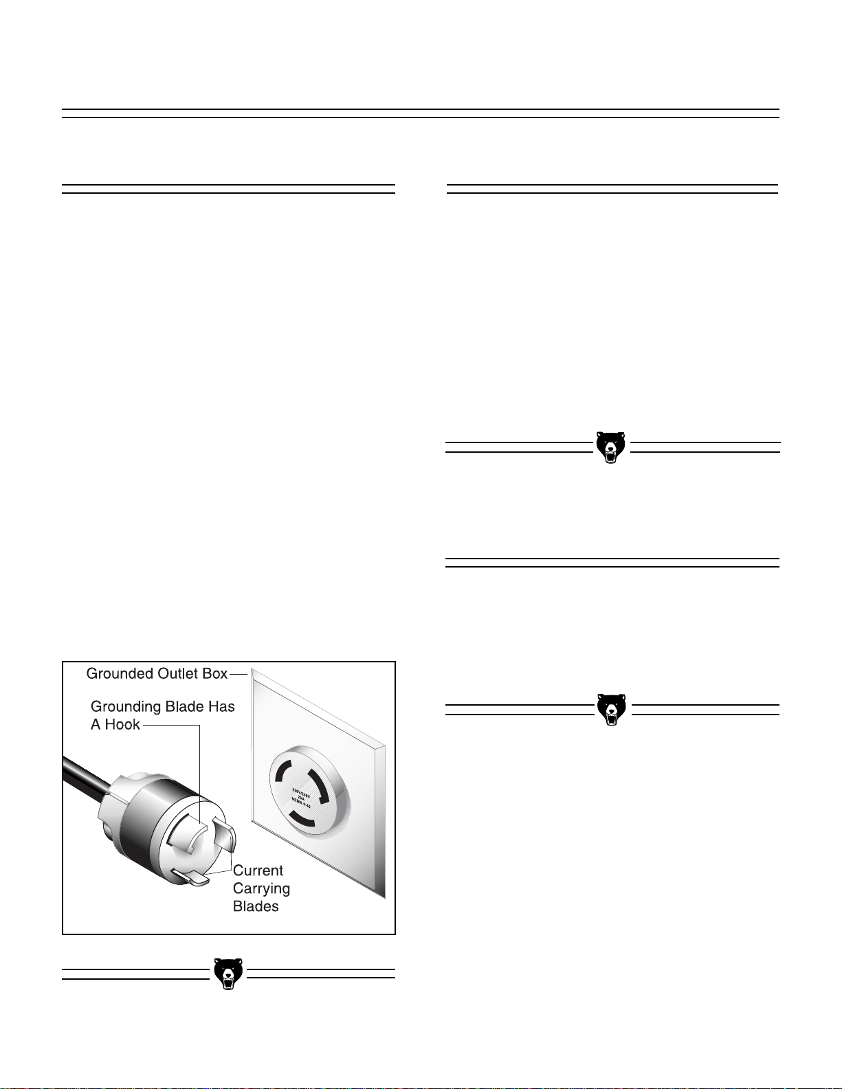
This machine does not come supplied with a plug,
therefore a suitable 220V plug must be wired in.
When operating at 220V, we recommend using a
NEMA-style 6L-15 plug and outlet. See Figure 1.
You may also “hard-wire” the machine directly to
your panel, provided you place a disconnect
switch near the machine. Check the electrical
codes in your area for specifics on wiring requirements.
Under normal use, the motor draws approximately 20 amps @ 220V. We recommend a 25 amp
circuit breaker for 220V operation. This should be
satisfactory for normal use while providing
enough protection against motor damage caused
by power surges.
SECTION 2: CIRCUIT REQUIREMENTS
Figure 1. Typical 220V 3-prong plug and outlet.
We do not recommend the use of extension cords
on 220V equipment. It is much better to arrange
the placement of your equipment and the installed
wiring to eliminate the need for extension cords.
Should it be necessary to use an extension, make
sure the cord is rated Hard Service (Grade S) or
better. Refer to the chart in Section 1: Safety
Instructions to determine the minimum gauge for
the extension cord. The extension cord must also
contain a ground wire and plug pin. Always repair
or replace extension cords when they become
worn or damaged.
Extension Cords
Your G7211 machine comes pre-wired for 220
volt operation. A wiring diagram is provided at the
back of this manual should it be necessary to
repair or revise the wiring. Always utilize a qualified electrician when doing any electrical work on
this equipment.
Wiring Diagram
Page 8
-6-
G7211/7212 24" Bandsaw
The Model G7212 has a 7.5 H.P. motor configured to operate under three-phase electrical service. Generally this type of electrical supply is only
found in commercial or industrial locations.
Connection to three-phase service should only be
done by a qualified electrician.
If you do not have three-phase service available a
phase converter can be utilized in conjunction
with a 220V single phase power supply. Refer to
the Grizzly catalog for a complete range of phase
converters.
3-Phase Operation Notes
We have covered some basic electrical
requirements for the safe operation of your
Bandsaw. These requirements are not necessarily comprehensive. You must be sure
that your particular electrical configuration
complies with local and state codes. Ensure
compliance by checking with your local
municipality or a licensed electrician.
Page 9

G7211/7212 24" Bandsaw -7-
SECTION 3: INTRODUCTION
Commentary
We are proud to offer the Models G7211/G7212
24" Bandsaws. These bandsaws are part of a
growing Grizzly family of fine woodworking
machinery. When used according to the guidelines set forth in this manual, you can expect
years of trouble-free, enjoyable operation and
proof of Grizzly’s commitment to customer satisfaction.
The Models G7211/G7212 are woodcutting bandsaws with powerful 5 H.P. or 7.5 H.P. motors, cast
iron fence, miter gauge, 4" dust port, foot brake
and micro-adjustable ball-bearing guides. They
feature an all steel construction frame and cast
iron table. A complete range of blades with widths
from
1
⁄2" to 11⁄4" and various tooth styles are avail-
able in the current Grizzly catalog for prices and
ordering information.
We are also pleased to provide this instructional
manual with the Model G7211/G7212 24"
Bandsaws. It was written to guide you through
assembly, review safety considerations, and
cover general operating procedures. It represents
our effort to produce the best documentation possible. If you have any comments regarding this
manual, please write to us at the address below:
Grizzly Industrial, Inc.
C
/O Technical Documentation
P.O. Box 2069
Bellingham, WA 98227-2069
Most importantly, we stand behind our machines.
If you have any service questions or parts
requests, please notify us using one of the following contacts:
Grizzly Industrial, Inc.
1203 Lycoming Mall Circle
Muncy, PA 17756
Phone:(570) 546-9663
Fax:(800) 438-5901
E-Mail: techsupport@grizzly.com
Web Site: http://www.grizzly.com
The specifications, drawings, and photographs
illustrated in this manual represent the Model
G7211/G7212 as supplied when the manual was
prepared. However, owing to Grizzly’s policy of
continuous improvement, changes may be made
at any time with no obligation on the part of
Grizzly. Whenever possible, though, we send
manual updates to all owners of a particular tool
or machine. Should you receive one, we urge you
to insert the new information with the old and keep
it for reference.
To operate this or any power tool safely
and efficiently, it is essential to become as
familiar with it as possible. The time you
invest before you begin to use your Model
G7211/G7212 will be time well spent. DO
NOT operate this machine until you are
completely familiar with the contents of this
manual. Serious personal injury may occur.
Page 10
-8-
G7211/7212 24" Bandsaw
Unpacking
The bandsaw is shipped from the factory in a
carefully packed carton. If you find the machine to
be damaged after you’ve signed for delivery and
the truck and driver are already gone, you will
need to file a freight claim with the carrier. Save
the containers and all packing materials for
inspection by the carrier or their agent. Without
the packing materials, filing a freight claim can be
difficult. If you need advice regarding this situation, please call us immediately.
When you are completely satisfied with the condition of your shipment, you should inventory its
parts.
The G7211/G7212 is a very heavy machine
with a shipping weight of 725 lbs. DO NOT
over-exert yourself while unpacking or
moving your machine – get assistance. In
the event that your bandsaw must be
moved up or down a flight of stairs, be sure
that the stairs are capable of supporting the
combined weight of people and the
machine. Serious personal injury may
occur.
Parts Inventory
NOTICE
Save all containers and packing materials
until you are satisfied that your bandsaw
has arrived in good condition. Freight company adjusters will want to inspect those
materials in the event that a freight claim
must be made.
Take a quick inventory of the parts and put them
aside for assembly later. After all the parts have
been removed from the container, you should
have:
• Bandsaw Assembly
• Fence Assembly
• Miter Gauge
• Hardware
Cap Screws 5/16" - 18 x 21/2"2
Fence Rail Spacers 2
Fence Rail 1
In the event that any non-proprietary parts are
missing (e.g. a bolt, nut or a washer), we would
be glad to replace them, or, for the sake of expediency, replacements can be obtained at your
local hardware store.
Page 11
G7211/7212 24" Bandsaw -9-
Clean Up
The unpainted surfaces are coated with a waxy oil
to protect it from corrosion during shipment.
Remove this protective coating with a solvent
cleaner or citrus-based degreaser such as
Grizzly’s G7895 Degreaser. Avoid chlorine-based
solvents as they may damage painted surfaces
should they come in contact. Always follow the
usage instructions on the product you choose for
clean up.
Site Considerations
FLOOR LOAD
Your G7211/G7212 Bandsaw represents a large
weight load in a small footprint. Most commercial
floors are suitable for the Model G7211/G7212.
Some residential floors may require additional
build up to support both machine and operator.
WORKING CLEARANCES
Working clearances can be thought of as the distances between machines and obstacles that
allow safe operation of every machine without limitation. Consider existing and anticipated machine
needs, size of material to be processed through
each machine, and space for auxiliary stands
and/or work tables. Also consider the relative
position of each machine to one another for efficient material handling. Be sure to allow yourself
sufficient room to safely run your machines in any
foreseeable operation.
LIGHTING AND OUTLETS
Lighting should be bright enough to eliminate
shadow and prevent eye strain. Electrical circuits
should be dedicated or large enough to handle
combined motor amp loads. Outlets should be
located near each machine so power or extension
cords are not obstructing high-traffic areas. Be
sure to observe local electrical codes for proper
installation of new lighting, outlets, or circuits.
Make your shop “child safe”. Ensure that
your workplace is inaccessible to youngsters by closing and locking all entrances
when you are away. Never allow visitors in
your shop when assembling, adjusting or
operating equipment.
Many of the solvents commonly used to
clean machinery can be highly flammable,
and toxic when inhaled or ingested. Always
work in well-ventilated areas far from
potential ignition sources when dealing
with solvents. Use care when disposing of
waste rags and towels to be sure they do
not create fire or environmental hazards.
Keep children and animals safely away
when cleaning and assembling this
machine.
Do not use gasoline or other petroleumbased solvents to remove this protective
coating. These products generally have low
flash points which makes them extremely
flammable. A risk of explosion and burning
exists if these products are used. Serious
personal injury may occur.
All die-cut metal parts have a sharp edge
(called “flashing”) on them after they are
formed. This is generally removed at the
factory. Sometimes a bit of flashing might
escape inspection, and the sharp edge may
cause cuts or lacerations when handled.
Please examine the edges of all die-cut
metal parts and file or sand the edge to
remove the flashing before handling.
Page 12

-10-
G7211/7212 24" Bandsaw
SECTION 4: ASSEMBLY
Fence
Most of your G7211/G7212 24'' Bandsaw has
been assembled at the factory. Only the fence
assembly requires installation.
To mount the fence to the bandsaw table:
1. Mount the front rail to the table using two (2)
5
/16 - 18 x 21/2'' Cap Screws and the two (2)
Spacers provided. See Figure 2.
2. Loosen the fence lock knob and slide the
fence onto the rail.
Figure 2. Front rail in place and fence installed.
DO NOT attempt any step of assembly,
adjustments, or maintenance while your
Model G7211/G7212 is running. Ensure that
the switch is off, power is disconnected and
moving parts have stopped before making
adjustments. Failure to comply may result
in serious personal injury.
Page 13

G7211/7212 24" Bandsaw -11-
SECTION 5: ADJUSTMENTS
Tracking
To adjust the tracking:
1. Disconnect the bandsaw from the power
source and open the top and bottom wheel
covers. Adjust the upper and lower guide
assemblies away from the blade.
2. Loosen the lock nut on the tracking knob.
See Figure 3. Rotate the upper wheel by
hand and adjust the tracking knob (turn the
tracking knob clockwise to track the blade
in, counterclockwise to track out) until the
flat body of the blade tracks in the center of
the upper wheel. Turn the wheel at least
three full turns to ensure that the blade is
tracking in its final position.
Figure 3. Tracking knob adjustment location.
Tracking Knob
Use extreme care when turning the bandsaw
wheel. The upper wheel may have sharp
edges and any procedures which require
work in close proximity to the bandsaw
blade could result in serious injury.
Tension
Final blade tension ultimately depends on the
type and size of blade you use. To adjust the tension:
1. Raise the blade guard to its fully retracted
position.
2. Press, with moderate pressure, on the face
of the blade with your thumb.
3. Turn the tension wheel until the blade
deflects about
1
/4". See Figure 4.
4. Make the other adjustments to the saw and
test run it. If the blade is not cutting properly, the tension may need to be increased.
Remember, thin blades require less tension
than wide blades.
5. Reduce the blade tension when the band-
saw is not in use. This will help prevent premature wear or breakage of the blade
and/or rubber tires.
Figure 4. Tension wheel adjustment location.
Tension Wheel
Page 14

-12-
G7211/7212 24" Bandsaw
Figure 6. Wheel alignment adjusting knobs.
Adjusting Knobs
Figure 5. Wheel alignment conditions.
For proper operation of the bandsaw it is important that the upper and lower wheels be aligned
so they are in the same plane. See Figure 5 to
understand the relationship between the wheels.
Wheel Alignment
The adjustment knobs on the upper wheel (See
Figure 6) can be used to correct for deviation in
parallelism between the two wheels. Although this
has been set at the factory, it is a good idea to
check it occasionally to assure proper operation
of your bandsaw. Loosen the check nuts and
adjust as necessary by turning one knob in and
the other knob about the same amount. Adjust in
small increments and check the measurement
between the wheels until the wheels are in alignment.
On the G7211/7212 it is not possible to lay a
straightedge across the two wheels to check
coplanarity and parallelism because of the
arrangement of the wheels in the cabinet. The
wheel relationship can be checked by clamping
two blocks of exactly the same size (must be at
least 2" high to extend beyond the cabinet) and
squareness to each wheel (use the large holes in
the wheels for the clamp), then use a straightedge
to check the wheel position. It will be necessary to
remove the fence and the table to perform this
check.
If the wheels are not coplanar, the bearing mount
on the lower wheel can be adjusted to move the
wheel position in or out, or the wheel can be
shimmed on its shaft. This is a major service procedure, however, and should be undertaken very
carefully. Normally the positioning of the wheels
will not change as long as the saw is properly
cared for and is not dropped or tipped onto its
back or side. Contact Customer Service for more
information on wheel alignment if you are experiencing difficulty.
Page 15

G7211/7212 24" Bandsaw -13-
5. Install your blade of choice. Track and ten-
sion as per the instructions in this manual.
6. Move the blade guide assembly so the
bearing guides are
1
/16" behind blade gul-
lets. Tighten the guide assembly.
7. Now rotate the bearing guide shafts until the
bearings are approximately
1
/64'' from the
blade. Hold the shafts in place with a screw
driver and tighten the bearing guide lock
nuts. The guide bearing, when adjusted correctly, should have a slight drag against the
blade. If the guide bearings pinch the blade,
it will damage the bearing guides and blade.
8. Slide the rear support bearing until it is approx-
imately
1
/32'' from the blade and tighten.
NOTICE
The bearing guide shaft lock nuts should
only be as loose as necessary to allow the
shafts to rotate. If they are too loose it will
be very difficult, if not impossible, to adjust
the guides accurately.
Normally Steps 1-4 are implemented prior to
installing a new blade. Refer to Figure 8 to iden-
tify the components of the guide assembly.To
adjust the lower guides:
1. Loosen the lower guide lock nuts and
thread the shafts out so the blade guides
are away from the blade.
2. Loosen the setscrew that holds the rear
support bearing in place and slide it back.
3. Loosen the bolts that hold the lower guide
assembly in place and slide the lower guide
back.
Lower Guides
Normally Steps 1-4 are implemented prior to
installing a new blade. Refer to Figure 7 to iden-
tify the components of the guide assembly. To
adjust the upper guides:
1. Loosen the bearing guide shaft lock nuts.
2. The bearing guides are mounted on an
eccentric shaft. With a regular screwdriver,
rotate the guides away from the blade.
3. Loosen the cap screw holding the rear sup-
port bearing in place and slide the rear support bearing away from the blade.
4. Loosen the cap screw holding the blade
guide assembly in place and slide it back
away from the blade.
Figure 7. Upper blade guide assembly.
Lock Nuts
Rear Support Bearing
Bearing Guides
Guide
Assembly
Upper Guides
Page 16

-14-
G7211/7212 24" Bandsaw
To adjust the positive stop so the table will be perpendicular to the blade:
1. Loosen the trunnion lock handle and check
nut locking the positive stop adjusting bolt.
See Figure 9.
2. Raise the upper blade guide assembly up
and stand a machinist’s square or
adjustable square on the table next to the
side of the blade. Adjust the positive stop
adjusting bolt to raise or lower the table until
the table is 90° to the blade.
3. Secure the trunnion lock handle and lock the
positive stop adjusting bolt by tightening the
lock nut. Ensure that the bolt does not turn
while tightening the lock nut.
4. Adjust the pointer on the table so that i
points directly to 0˚.
Figure 9. Location of positive stop adjustment.
Positive Stop
Positive Table Stop
4. Install blade. Track and tension according
to the instructions in this manual. It is recommended that you adjust the upper guides
first, then the lower.
5. Slide the lower guide forward so the bearing
guides are
1
/16" behind blade gullets.
Tighten the lower guide assembly.
6. Thread in the lower blade guide adjusters
until the blade guides are approximately
1
/64'' from the blade. Tighten the lock nuts.
7. Slide the rear support bearing until it is
approximately
1
/32'' from the blade and tighten.
Figure 8. Lower blade guide assembly.
Lock Nut
Blade Guide Adjuster
Blade Guide
DO NOT make adjustments while the bandsaw is running. Ensure that the switch is off,
power is disconnected and moving parts
have stopped before making adjustments.
Failure to comply may result in serious personal injury.
Page 17

G7211/7212 24" Bandsaw -15-
Pre-Run Check
Bandsaw Blades
SECTION 6: OPERATIONS
The bandsaw is one of the most versatile
machines in the shop. It can cut miters, compound angles, simple and complex curves, circles, and a wide variety of irregular shapes. It can
also rip and crosscut, as well as cut a variety of
joints. The bandsaw will also resaw stock into
thinner boards.
There are many adjustment points and compensating differences to consider when operating this
type of saw. Therefore, cutting results can be
somewhat unpredictable if some or all of the crucial adjustments are neglected. Here are a few
simple things you can do to increase the predictability of your bandsaw’s performance:
1. Always use a sharp, high-quality blade.
Although you might save a few dollars initially, buying a cheap blade will give you
cheap results. As a rule, spending more
now saves you money later.
2. Use the right blade for the job. Resawing
with a
1
/16" blade or doing scrollwork with a
1" blade are extreme examples of using the
wrong blade for the job.
3. Set the top guide assembly so it is just
above the top of the work at all times.
4. Allow the saw to cut. Don’t force the
workpiece into the blade. When cutting
curves or irregular shapes, remember that
while negotiating a curve, the blade should
still be cutting wood. Simply turning the
workpiece will only bind the blade and could
break it.
5. Maintain your bandsaw in top condition.
See the following section of this manual for
maintenance procedures.
A bandsaw blade is a delicate piece of steel subjected to tremendous strain. Be sure you use
quality blades of the proper width for the various
types of cutting operations. The Grizzly
G7211/7212 24" Bandsaw accepts 154
1
⁄2" blades
ranging in widths from
1
⁄2" to 11⁄4".
Always use the widest blade possible for the
workpiece you are cutting. Use narrow blades
only for sawing small, abrupt curves and for fine,
delicate work. Bandsaw blades can be purchased
welded, set, and sharpened ready-for-use from
Grizzly’s catalog or website.
Always select and use good-quality saw blades
and choose the right blade for the job. Poor quality blades and improper use are often the cause of
premature blade failure.
Many conditions can lead to breakage. Blade
breakage is, in some cases, unavoidable, since it
is the natural result of the peculiar stresses that
bandsaw blades are subjected to. Blade breakage is also due to avoidable causes. Avoidable
breakage is most often the result of poor care or
judgement on the part of the operator when
mounting or adjusting the blade or support
guides. The most common causes of blade breakage are: (1) faulty alignment and adjustment of
the guides; (2) forcing or twisting a wide blade
around a curve or short radius; (3) feeding too
fast; (4) tooth dullness or absence of sufficient
set; (5) excessive tension; (6) upper blade guide
assembly set too high above the workpiece; (7)
using a blade with a lumpy or improperly finished
weld; and (8), continuously running the bandsaw
when not in use.
Page 18

-16-
G7211/7212 24" Bandsaw
Figure 10. Side and front views of a standard
bandsaw blade.
Gullet Line
Gullet
Tooth
To remove the blade, ensure the power is disconnected and:
1. Loosen tension on the blade by turning the
tension control knob.
2. Remove the table insert and table pin.
3. Remove the fence and front fence rail.
4. Adjust upper guide bearings and lower
guide blocks away from the blade.
5. Open the upper and lower wheel covers
and slide the blade off both wheels. Use
caution, the blades are sharp!
6. Maneuver the blade through the table slot
then turn it 90˚ to move the blade between
the fence rail and the table.
To replace the blade, ensure that the power is disconnected and:
1. Slide the blade behind the fence rail and
through the table slot, ensuring that the
teeth are pointing down toward the table.
If the teeth will not point downward in any ori-
entation, the blade is inside out. See Figure
10 for typical blade geometry. Put on heavy
gloves, remove the blade, and twist it until it
is right side out. Re-install the blade.
2. Slip the blade through the upper and lower
guides and mount over the upper and lower
wheels.
3. Apply tension to the blade by turning the
tension control knob. Refer to blade tensioning instructions earlier in this section.
Changing Blades
4. Rotate the upper wheel manually and check
blade tracking.
5. Adjust the upper guide bearings and lower
guide blocks as described earlier in this
section.
6. Close the wheel covers. Turn the yellow
guard locking knobs to lock them shut.
7. Replace the table insert and table pin, being
sure not to use excessive force.
8. Replace the fence rail and fence.
Use extreme caution when replacing blades.
Teeth are dangerously sharp and coiled
blades are prone to spring when released
from their packaging. Use gloves and safety
glasses or goggles whenever handling
blades. Failure to do so could result in serious personal injury.
Page 19

G7211/7212 24" Bandsaw -17-
Changing Speeds
The G7211/G7212 24" Bandsaw provides two
speeds, 2800 and 3500 FPM, to make cutting
easier. In many applications, blade speed is a
matter of personal preference. Usually the higher
speed will produce the best results, but if the
motor is straining while cutting, try a slower blade
speed. Blade speed is also affected by the type of
wood, denser woods need a different speed than
a softer, lighter wood. Ultimately blade speed is a
matter of trial and error. Whenever possible test
the cut on a scrap piece first to gauge how well
the blade is cutting at the selected speed.
To change bandsaw speeds:
1. Turn the bandsaw power switch off and dis-
connect from power source.
2. Use a
9
⁄16" open end wrench to loosen the
lock nut and lock bolt on the lock system.
See Figure 11. This provides room to turn
the adjuster nut.
3. Use a
3
⁄4" box wrench to loosen the adjuster
nut. Loosen as needed to allow the shaft to
move. See Figure 12.
4. Select the pulleys for the speed desired. The
rear or smaller motor pulley provides the
slower, 2800 FPM, speed, while the front
pulleys are for the faster 3500 FPM speed.
See Figure 13.
5. Move the V-belt to the pair of pulleys which
provide the desired speed.
6. Tighten the belt by sliding the adjuster nut
and shaft up or down as needed.
7. Tighten the adjuster nut.
8. Bring the lock bolt head snug against the
adjuster nut. Tighten the lock nut.
Figure 11. Backing off lock bolt.
Figure 12. Loosening the adjuster nut.
Figure 13. View of pulleys behind lower wheel.
Page 20

-18-
G7211/7212 24" Bandsaw
Stacked Cuts
One of the benefits of a bandsaw is its ability to
cut multiple copies of a particular shape by stacking a number of workpieces together.
Before making stacked cuts, it is essential to
ensure that both the table and the blade are properly adjusted to 90°. Otherwise, any error will be
compounded with each piece cut from the top to
the bottom of the stack.
To complete a stacked cut:
1. Align your pieces from top to bottom to
ensure that each piece has adequate scrap
to provide a clean, unhampered cut.
2. Using brads in the waste portion of each
piece, secure all the pieces together.
3. Lay out the shape you intend to cut on the
face of the top piece.
4. Make relief cuts perpendicular to the outline
of your intended shape in areas where
changes in blade direction could strain the
woodgrain or cause the blade kerf to bind.
5. Cut the stack of pieces as though you were
cutting a single piece. Follow you layout line
with the blade kerf on the waste side of your
line.
Ripping is the process of cutting a board into two
or more thinner boards. The maximum board
width that can be ripped is limited by the distance
between the blade and the support column.
Maximum cutting width for this bandsaw is 24".
The important consideration when ripping is blade
selection. Generally, the wider the blade, the better. In most applications, a hook or skip tooth style
will be sufficient. Also, since most ripped lumber
will be planed or sanded smooth, you can choose
blades with fewer teeth-per-inch. While blades
with fewer teeth-per-inch produce rougher cuts,
these types of blades offer larger gullet capacities
for clearing sawdust, less heat buildup, and yield
more horsepower per tooth.
To perform ripping operations:
1. The bandsaw must be adjusted correctly.
See Blade Tension/Tracking section.
2. The table must be square to the blade. See
Table Adjustment Section.
3. Use the widest blade available. The blade
must also be in good condition.
4. Use a fence to guide work.
5. Draw a reference line on the edge of the
board.
6. Support ends of the board if necessary.
7. Feed work slowly and evenly.
Ripping
Page 21

G7211/7212 24" Bandsaw -19-
Cutting Curves
When cutting curves, simultaneously feed and
turn the stock carefully so that the blade follows
the layout line without being twisted. If a curve is
so abrupt that it would be necessary to repeatedly back up and cut a new kerf, use either a narrower blade or a blade with more set to avoid that.
A blade with more set can cut relatively tighter
radii; however, the cut is usually rougher than cuts
produced by blades with medium set.
Always make short cuts first, then proceed to the
longer cuts. Relief cuts will also reduce the
chance that the blade will be pinched or twisted.
Relief cuts are cuts made through the waste portion of the workpiece and are stopped at the layout line. As you cut along the layout line, waste
wood is released from the workpiece, alleviating
any pressure on the back of the blade. Relief cuts
also make backing the workpiece out easier, if
needed. The table below lists blade widths for this
bandsaw and corresponding minimum radii each
blade will cut.
BLADE WIDTH
1
/2
"
5
/8"
3
/4"
1"
MINIMUM RADII
2
1
/2
"
3
3
/4"
5
1
/2"
7
1
/2"
Resawing
Resawing is the process of cutting a board into
two or more thinner boards. Each new board is
the same width and length as the original board,
but the thickness is less. The maximum board
width that can be resawn is limited by the maximum cutting height of the bandsaw. Maximum
cutting height for this bandsaw is 15
3
/4".
Use common sense when resawing; attempting to
resaw a board that is too wide or too dense may
put excessive strain on the blade and be unsafe.
Again, the important consideration when resawing is blade selection. When selecting a blade,
keep in mind that generally, a wider blade is easier to control. The blade should be of the best
quality in order to handle the increased stress. In
most applications a hook or skip tooth style will
work fine. Also, since most resawn lumber will be
planed smooth, you can choose blades with
fewer teeth per inch (3 to 6). While blades with
fewer teeth per inch produce rougher cuts, these
types of blades offer larger gullet capacities for
clearing sawdust, less heat build up, and yield
more horsepower per tooth.
NOTE: When operating with wide blades, run the
bandsaw at the slowest speed.
To resaw lumber, follow the procedure below:
1. The blade must be adjusted correctly.
2. The table must be square to the blade.
3. Use the widest blade that will fit this saw
(11/4"). The blade must also be in good condition.
4. Use the fence to guide the work.
5. Support ends of the board if necessary.
6. Feed work slowly and evenly.
When using a fence to guide the board, the actual line of cut may not be parallel to the fence. In
fact, most bandsaw blades will not cut exactly
parallel to the fence (even when the fence is set
parallel to the miter gauge slot). There are usually a number of reasons for this:
1. Teeth are set unequally from side to side.
2. Teeth are dull on one side.
3. Blade tension is too tight or too loose.
IMPORTANT: Do not force the wood into the
blade during cutting. This will distort the blade,
cause excessive heat and often results in blade
breakage as well as miscut lumber.
Page 22

-20-
G7211/7212 24" Bandsaw
SECTION 7: MAINTENANCE
V-Belts
To ensure optimum power transmission from the
motor to the blade, the V-belt must be in good
condition and operate under proper tension. Belts
should be checked for cracks, fraying and wear.
Belt tension should be checked at least every 3
months; more often if the bandsaw is used daily.
The V-belts are accessed via the bottom cover:
1. Squeeze the center of each V-belt.
2. Note the amount of deflection. Deflection
should be approximately
3
⁄4".
The table and other non-painted surfaces on the
Model G7211/7212 should be protected against
rust and pitting. Wiping the saw clean after every
use ensures that moisture from wood dust isn’t
allowed to trap moisture against bare metal surfaces.
Some woodworkers recommend using automotive paste wax on exposed steel and cast iron surfaces. The wax provides a layer of protection, as
well as reducing friction between lumber and the
table, making cuts faster and smoother. Avoid
waxes that contain silicone or other synthetic
ingredients. These materials can find their way
into lumber that’s being worked, and can make
staining and finishing difficult. If you use paste
wax, make sure that it’s 100% Carnauba wax.
NOTICE
Do not use paraffin or similar waxes on your
saw’s table. They can leave residues which
will make cutting more difficult over time. Do
not use silicon based lubricants. They can
rub off onto the wood and prevent it from
taking stains and finishes properly.
Table
Operating this equipment has the potential
to propel debris into the air which can cause
eye injury. Always wear safety glasses or
goggles when operating equipment.
Everyday glasses or reading glasses only
have impact resistant lenses, they are not
safety glasses. Be certain the safety glasses
you wear meet the appropriate standards of
the American National Standards Institute
(ANSI).
DO NOT make adjustments or attempt maintenance procedures while the Model
G7211/G7212 is running. Ensure that the
switch is off, power is disconnected and
moving parts have stopped before making
adjustments. Failure to comply may result
in serious personal injury.
Page 23

G7211/7212 24" Bandsaw -21-
Shielded and pre-lubricated ball bearings require
no lubrication for the life of the bearings. All bearings are standard sizes and replacements can be
purchased from our parts department or bearing
supply store.
As for other items on this machine, such as
adjustment controls, an occasional “shot” of light
oil is just about all that is necessary. Before applying, however, wipe off any sawdust with a clean
cloth, towel or dry paint brush and spray on the
lubricant. Ensure that oil does not get on the pulleys or V-belts because it could cause belt deterioration and slipping.
Lubrication
Always be aware of the condition of your bandsaw
before using it. Routinely check the condition of
the following items and repair or replace as necessary.
1. Loose mounting bolts.
2. Worn switch.
3. Worn or damaged blade.
4. Worn or damaged support bearings or
guide bearings.
Miscellaneous
Page 24

-22-
G7211/7212 24" Bandsaw
The following pages contain general machine
data, parts diagrams/lists, and Warranty/Return
information for your Model G7211/G7212 24"
Bandsaw.
If you need parts or help in assembling your
machine, or if you need operational information,
we encourage you to call our Service Department.
Our trained service technicians will be glad to help
you.
If you have comments dealing specifically with
this manual, please write to our Bellingham,
Washington location using the address in the
Introduction. The specifications, drawings, and
photographs illustrated in this manual represent
the Model G7211/G7212 as supplied when the
manual was prepared. However, due to Grizzly’s
policy of continuous improvement, changes may
be made at any time with no obligation on the part
of Grizzly. Whenever possible, though, we send
manual updates to all owners of a particular tool
or machine. Should you receive one, add the new
information to this manual and keep it for reference.
We have included some important safety measures that are essential to this machine’s operation. While most safety measures are generally
universal, Grizzly reminds you that each workshop is different and safety rules should be con-
sidered as they apply to your specific situation.
We recommend you keep a copy of our current
catalog for complete information regarding
Grizzly's warranty and return policy. If you need
additional technical information relating to this
machine, or if you need general assistance or
replacement parts, please contact the Service
Department listed in Section 3: Introduction.
Additional information sources are necessary to
realize the full potential of this machine. Trade
journals, woodworking magazines, and your local
library are good places to start.
The Model G7211/G7212 was specifically
designed for wood cutting operations. DO
NOT MODIFY AND/OR USE THIS BANDSAW
FOR ANY OTHER PURPOSE. Modifications
or improper use of this tool will void the warranty. If you are confused about any aspect
of this machine, DO NOT use it until you
have answered all your questions. Serious
personal injury may occur.
Like all power tools, there is danger associated with the Model G7211/G7212 24"
Bandsaw. Use the tool with respect and
caution to lessen the possibility of mechanical damage or operator injury. If normal
safety precautions are overlooked or
ignored. Serious personal injury may occur.
Always wear ANSI-approved safety glasses
or goggles when operating equipment Do
not allow visitors into your workshop when
testing or operating equipment unless they
also have proper safety glasses. Serious
personal injury may occur.
SECTION 8: CLOSURE
Page 25

G7211/7212 24" Bandsaw -23-
Design Type: ......................................................................................................Floor Model
Overall Dimensions:
Table ............................................................................................................21
1
⁄4'' x 26''
Overall Height ........................................................................................................80
1
⁄2''
Height From Floor to Table ......................................................................................35''
Width ...................................................................................................................... 40''
Depth including Fence ..............................................................................................29''
Shipping Weight ................................................................................................725 lbs.
Crate Size ................................................................................39" L x 27
1
⁄2" W x 87" H
Footprint ......................................................................................................35" x 19
1
⁄2
"
Cutting Capacity:
Left of Blade ..............................................................................................................24''
Height Capacity (Overall) ..........................................................................................14''
Height Capacity (at Blade) ....................................................................................15
3
⁄4''
Table Tilt ....................................................................................................45° R, 10° L
Construction:
Table ..................................................................................Precision Ground Cast Iron
Wheels ......................................................Fully balanced Cast Iron with Rubber Tires
Rip Fence ........................................................................................................Cast Iron
Wheel Covers ................................................................................Pre-Formed Steel
Guides ......................................................................................All Ball Bearing Guides
Motor:
Type..............................................................................TEFC Capacitor Start Induction
Bearings................................................................Shielded & Lubricated Ball Bearings
Switch ........................................................Magnetic with Thermal Overload Protector
G7211
G7212
Horsepower ............................................5 HP ......................................7.5 HP
Phase ⁄ Cycle...............................Single Phase / 60 Hz...................3-Phase / 60 Hz
Voltage ....................................................220V ......................................220V
Amps ......................................................20 ..........................................24
RPM ........................................................3450 ......................................3450
Blades:
Sizes Available ......................................................................................11 @
1
⁄
2'' - 1
1
⁄
4''
Standard Blade Length ........................................................................................176
3
⁄4''
Blade Speeds ......................................................................................2800, 3500 FPM
Features:
..................................................................Micro-Adjustable Ball Bearing Blade Guides
..............................................................................................................Cast Iron Fence
....................................................................................................................Miter Gauge
....................................................................................................................4" Dust Port
......................................................................................................................Foot Brake
Specifications, while accurate, are not guaranteed.
Customer Service #: (570) 326-3806 • To Order Call: (800) 523-4777 • Fax #: (800) 438-5901
GRIZZLY MODEL G7211/12 24" BANDSAW
MACHINE DATA
SHEET
REVISED 08/00
Page 26

-24-
G7211⁄7212 24" Bandsaw
Ref# Part# Description
001 P7211001 BODY
002 P7211002 BEARING BASE
003 P6206 6206 BEARING
004 P7211004 SHAFT
005 PK27M KEY 7 X 7 X 25
006 P7211006 HEX NUT
3
⁄4 X 16NF
007 P7211007 BEARING COVER
008 P7211008 WASHER
3
⁄4"
009 P7211009 PAN SCREW
1
⁄4 X 5⁄8"
010 P7211010 ADJUSTING SCREW
011 P7211011 SPRING WASHER
3
⁄8"
012 P7211012 HEX SCREW
3
⁄8 X1 1⁄2"
013 P7211013 ADJUST WHEEL
014 P7211014 SET SCREW
5
⁄16 X 3⁄8"
015 P7211015 WASHER
3
⁄8"
016 P7211016 HEX SCREW
3
⁄8 X 1"
017 P7211017 BUSH
017A P7211017A HEX NUT
018 P7211018 LOCK SCREW
5
⁄16 X 3"
019 P7211019 UPPER WHEEL BASE
020 P7211020 BRACKET SHAFT
021 P7211021 SET SCREW
5
⁄16 X 3⁄8"
022 P7211022 ADJUST BRACKET
023 P7211023 ADJUST SCREW
024 P7211024 ELEVATOR BRACKET
025 P7211025 SPRING
026 P7211026 GUIDE SPINDLE
026A P7211026A SPINDLE BUSHING
027 P7211027 UPPER WHEEL GUIDE BRACKET
028 P7211028 C-RING S-20
029 P7211029 LEVER SHAFT
030 P7211030 BUSH
031 P7211031 LOCKING SCREW
032 P7211032 UPPER ADJUST BRACKET
033 P7211033 C-RING S-25
034 P6205 BEARING 6205
035 P7211035 UPPER WHEEL BEARING BASE
036 P7211036 UPPER WHEEL SHAFT
037 P7211037 BLADE WHEEL
038 P7211038 RUBBER COATING
039 P7211039 WASHER
3
⁄4"
040 P7211040 HEX NUT
3
⁄4 X 16NF
041 P7211041 UPPER GUARD
042 P7211042 LOWER GUARD
043 P7211043 HEX SCREW
1
⁄4 X1 1⁄4"
Ref# Part# Description
044 P7211044 BRAKE WHEEL
045 PVB36 V-BELT B-36 5L360
046 P7211046 *SEE CATALOG*
047 P7211047 CAP SCREW
1
⁄4 X1 1⁄4"
048 P7211048 BRAKE BELT LOCKING
049 P7211049 BRAKE BELT
050 P7211050 HEX SCREW
1
⁄4 X 5⁄8"
051 P7211051 HEX NUT
1
⁄4 X 5⁄8"
052 P7211052 BRAKE SWITCH
053 P7211053 MOTOR PULLEY
054 PVB25 V-BELT B-255 L250
055 P7211055 INTERMEDIATE WHEEL
056 P7211056 C-RING S-20
057 P6204 BEARING 6204
058 P7211058 INTERMEDIATE WHEEL SHAFT
059 P7211059 WASHER
1
⁄2"
059A P7211059A LOCK WASHER
060 P7211060 HEX NUT
1
⁄2"
061 P7211061 MOTOR
062 P7211062 MOTOR MOUNTING PLATE
063 P7211063 HEX SCREW
3
⁄8
X 2
1
⁄2
"
064 P7211064 BRAKE PEDAL
065 P7211065 SPRING
066 P7211066 DUST CHUTE
067 P7211067 BUSH
068 P7211068 GUIDE RAIL
069 P7211069 CAP SCREW
5
⁄16 X 2 1⁄2"
070 P7211070 SET SCREW
5
⁄16 X 1⁄2"
071 P7211071 RAIL COVER
072 P7211072 FENCE
073 P7211073 LOCKING KNOB
074 P7211074 WORKING TABLE
075 P7211075 INSERT
076 P7211076 SPRING PIN
077 P7211077 MITER GAUGE BAR
078 P7211078 POINTER
079 P7211079 PAN SCREW
3
⁄
16 X
1
⁄
4"
080 P7211080 PIN
081 P7211081 MITER GAUGE
082 P7211082 GUIDE DISC
083 P7211083 LOCKING SCREW
084 P7211084 TABLE GAUGE BRACKET
085 P7211085 SPRING WASHER
3
⁄8"
086 P7211086 HEX SCREW
3
⁄8 X 1 1⁄2"
087 P7211087 TRUNNION
G7211 PARTS LIST
Page 27

G7211⁄7212 24" Bandsaw -25-
Ref# Part# Description
088 P7211088 LOCKING HANDLE
089 P7211089 LOCKING HANDLE
090 P7211090 LOWER GUIDE BRACKET
091 P7211091 BLADE SUPPORT SHAFT
091B P6202 BEARING
091C P7211091C GUIDE SHAFT
091D P7211091D SPACER
091E P7211091E C-RING S-15
092 P7211092 HEX SCREW
093 P7211093 CAP SCREW
1
⁄4 X 5⁄8"
094 P7211094 SET SCREW
1
⁄4 X 3⁄8"
095 P7211095 UPPER GUIDE BRACKET
096 P7211096 LOCKING SHAFT
097 P7211097 GUIDE WHEEL
098 P7211098 GUIDE BAR BRACKET
099 P7211099 BLADE GUARD
100 P7211100 BLADE INTER GUARD
101 P7211101 HEX SCREW
1
⁄4 X 5⁄8"
102 P7211102 GUIDE BAR
103 P7211103 ELEVATOR HAND WHEEL
104 P7211104 GEAR
105 P7211105 GUIDE BAR CASE BRACKET
106 P7211106 WASHER
107 P7211107 NUT
1
⁄2"
108 P7211108 LOCK KNOB
109 P7211109 SCREW
1
⁄4 X 5⁄8"
110 P7211110 SCREW
3
⁄16 X 1 1⁄2"
111 P7211111 BRUSH
112 P7211112 WASHER
3
⁄16"
113 P7211113 NUT 3⁄16-24 NC
114 P7211114 STRAIN RELIEF
115 P7211115 MOTOR CORD
116 P7211116 SWITCH ON⁄OFF
117 P7211117 SCREW
118 P7211118 POWER CORD
120 P7211120 SCREW
125 P7211125 LABEL
The parts list for the G7212 is identical except
that Reference #61 Motor is a 7.5 H.P. horsepower, three-phase motor - G6249.
Page 28

-26-
G7211/7212 24" Bandsaw
G7211/G7212 PARTS DIAGRAM
32
21
1
26
31
16
30
15
26A
15
20
28
29
18
25
27
24
17
11
19
23
9
108
33
34
7
21
5
12
116
21
11
35
10
22
36
2
109
117
6
8
37
14
13
3
114
4
5
115
112
111
113
38
118
60
110
66
59
11
58
12
57
55
37
59A
54
49
63
17A
56
50
15
44
51
15
52
51
65
64
48
15
47
17
45
46
39
40
125
41
39
40
42
43
51
Page 29

G7211/7212 24" Bandsaw -27-
G7211⁄G7212 PARTS DIAGRAM
21
53
21
61
104
105
5
12
11
63
11
17A
12
91B
91B
93
101
91
62
11
17A
11
17A
72
107
100
8
95
106
102
96
11
98
17
31
15
16
103
99
8
101
78
79
73
83
77
80
81
97
82
120
68
69
90
67
93
91E
94
92
8
71
91D
75
91C
70
88
84
76
87
16
85
15
74
59
89
15
85
86
Page 30

-28-
G7211/7212 24" Bandsaw
To Foot Brake
G7211 Switch Wire Diagram
SINGLE PHASE
220 VOLT POWER SOURCE
1L1
2T1
T12T2
3L2 5L3
4T2
T3
4
6
6T3
13NO
1718
14NC
14
18
22
T
E
S
T
MAN
95 97
96 98
Ground
A
U
T
O
MOTOR
Page 31

G7211/7212 24" Bandsaw -29-
To Foot Brake
G7212 Switch Wire Diagram
THREE PHASE
220 VOLT POWER SOURCE
1L1
2T1
T12T2
3L2 5L3
4T2
T3
4
6
6T3
13NO
1718
14NC
18
22
T
E
S
T
MAN.
95 97
96 98
Ground
26
A
U
T
O
3
2
8
1
7
9
456
Motor
Page 32

-30-
G7211/7212 24" Bandsaw
Grizzly Industrial, Inc. warrants every product it sells for a period of 1 year to the original purchaser from
the date of purchase. This warranty does not apply to defects due directly or indirectly to misuse, abuse,
negligence, accidents, repairs or alterations or lack of maintenance. This is Grizzly’s sole written warranty
and any and all warranties that may be implied by law, including any merchantability or fitness, for any particular purpose, are hereby limited to the duration of this written warranty. We do not warrant or represent
that the merchandise complies with the provisions of any law or acts unless the manufacturer so warrants.
In no event shall Grizzly’s liability under this warranty exceed the purchase price paid for the product and
any legal actions brought against Grizzly shall be tried in the State of Washington, County of Whatcom.
We shall in no event be liable for death, injuries to persons or property or for incidental, contingent, special, or consequential damages arising from the use of our products.
To take advantage of this warranty, contact us by mail or phone and give us all the details. We will then
issue you a “Return Number’’, which must be clearly posted on the outside as well as the inside of the carton. We will not accept any item back without this number. Proof of purchase must accompany the merchandise.
The manufacturers reserve the right to change specifications at any time because they constantly strive to
achieve better quality equipment. We make every effort to ensure that our products meet high quality and
durability standards and we hope you never need to use this warranty.
Please feel free to write or call us if you have any questions about the machine or the manual.
Thank you again for your business and continued support. We hope to serve you again soon.
WARRANTY AND RETURNS
Page 33

CUT ALONG DOTTED LINE
9. How many of your woodworking machines are Grizzly? _____________
10. Which benchtop tools do you own? Check all that apply.
___1" x 42" Belt Sander ___6" - 8" Grinder
___5" - 8" Drill Press ___Mini Lathe
___8" Table Saw ___10" - 12" Thickness Planer
___8" - 10" Bandsaw ___Scroll Saw
___Disc⁄Belt Sander ___Spindle⁄Belt Sander
___Mini Jointer
___Other__________________________________________________
11. How many of the machines checked above are Grizzly? ____________
12. Which portable⁄hand held power tools do you own? Check all that apply.
___Belt Sander ___Orbital Sander
___Biscuit Joiner ___Palm Sander
___Circular Saw ___Portable Planer
___Detail Sander ___Saber Saw
___Drill⁄Driver ___Reciprocating Saw
___Miter Saw ___Router
___Other__________________________________________________
13. What machines⁄supplies would you like Grizzly Industrial to carry?
___12" Table Saw ___Radial Arm Saw
___12" Jointer ___Panel Saw
___Combination Planer⁄Jointer ___Brass Hardware
___Paint & Finishing Supplies ___Lumber
___Contractor’s Supplies
___Other__________________________________________________
14. What new accessories would you like Grizzly Industrial to carry?
___Builders Hardware ___Hand Tools
___Fasteners ___Wood Components
___Other__________________________________________________
15. What other companies do you purchase your tools and supplies from?
__________________________________________________________
__________________________________________________________
16. Do you think your purchase represents good value?
___Yes ___No
17. Would you recommend Grizzly Imports to a friend?
___Yes ___No
18. Would you allow us to use your name as a reference for Grizzly customers
in your area? Note: We never use names more than three times.
___Yes ___No
19. Comments:_________________________________________________
__________________________________________________________
__________________________________________________________
__________________________________________________________
__________________________________________________________
__________________________________________________________
__________________________________________________________
__________________________________________________________
1. How did you learn about us?
___Advertisement ___Friend
___Catalog ___Card Deck
___World Wide Web
___Other__________________________________________________
2. Which of the following magazines do you subscribe to.
___American Woodworker ___Practical Homeowner
___Cabinetmaker ___Shop Notes
___Family Handyman ___Today’s Homeowner
___Fine Homebuilding ___WOOD
___Fine Woodworking ___Wooden Boat
___Home Handyman ___Woodshop News
___Journal of Light Construction ___Woodsmith
___Old House Journal ___Woodwork
___Popular Mechanics ___Woodworker
___Popular Science ___Woodworker’s Journal
___Popular Woodworking ___Workbench
___Other__________________________________________________
3. Which of the following woodworking⁄remodeling shows do you watch?
___Backyard America ___The New Yankee Workshop
___Home Time ___This Old House
___The American Woodworker ___Woodwright’s Shop
___Other__________________________________________________
4. What is your annual household income?
___$20,000-$29,999 ___$60,000-$69,999
___$30,000-$39,999 ___$70,000-$79,999
___$40,000-$49,999 ___$80,000-$89,999
___$50,000-$59,999 ___$90,000 +
5. What is your age group?
___20-29 ___50-59
___30-39 ___60-69
___40-49 ___70 +
6. How long have you been a woodworker?
___0 - 2 Years ___8 - 20 Years
___2 - 8 Years ___20+ Years
7. How would you rank your woodworking skills?
___Simple ___Advanced
___Intermediate ___Master Craftsman
8. What stationary woodworking tools do you own? Check all that apply.
___Air Compressor ___Panel Saw
___Band Saw ___Planer
___Drill Press ___Power Feeder
___Drum Sander ___Radial Arm Saw
___Dust Collector ___Shaper
___Horizontal Boring Machine ___Spindle Sander
___Jointer ___Table Saw
___Lathe ___Vacuum Veneer Press
___Mortiser ___Wide Belt Sander
___Other__________________________________________________
Name ____________________________________________________________________________________
Street ____________________________________________________________________________________
City ______________________________________________________________State________Zip_________
Phone Number_______________________E-Mail_______________________FAX________________________
MODEL _G7211/7212 24" Bandsaw____ Order #______________________________________________
The following information is given on a voluntary basis. It will be used for marketing purposes to help us develop better products and services. Of
course, all information is strictly confidential.
WARRANTY CARD
Page 34

TAPE ALONG EDGES--PLEASE DO NOT STAPLE
FOLD ALONG DOTTED LINE
FOLD ALONG DOTTED LINE
GRIZZLY INDUSTRIAL, INC.
P.O. BOX 2069
BELLINGHAM, WA 98227-2069
Place
Stamp
Here
Name_______________________________
Street_______________________________
City______________State______Zip______
Send a Grizzly Catalog to a friend:
 Loading...