

Page 1
12" X 351⁄2" WOOD LATHE
MODEL G5979
INSTRUCTION MANUAL
COPYRIGHT © FEBRUARY, 2002 BY GRIZZLY INDUSTRIAL, INC.
WARNING: NO PORTION OF THIS MANUAL MAY BE REPRODUCED IN ANY SHAPE
OR FORM WITHOUT THE WRITTEN APPROVAL OF GRIZZLY INDUSTRIAL, INC.
PRINTED IN CHINA.
Page 2

WARNING
Some dust created by power sanding, sawing, grinding, drilling, and other construction activities contains
chemicals known to the State of California to cause
cancer, birth defects or other reproductive harm. Some
examples of these chemicals are:
• Lead from lead-based paints.
• Crystalline silica from bricks, cement, and other
masonry products.
• Arsenic and chromium from chemically treated
lumber.
Your risk from these exposures varies, depending on
how often you do this type of work. To reduce your
exposure to these chemicals: work in a well ventilated
area, and work with approved safety equipment, such
as those dust masks that are specially designed to filter out microscopic particles.
Page 3

Table Of Contents
PAGE
1. SAFETY
SAFETY RULES FOR ALL TOOLS ......................................................................2-3
ADDITIONAL SAFETY INSTRUCTIONS FOR G5979 ............................................4
2. CIRCUIT REQUIREMENTS
110V OPERATION ..................................................................................................5
GROUNDING ..........................................................................................................5
EXTENSION CORDS ..............................................................................................5
3. INTRODUCTION
COMMENTARY........................................................................................................6
UNPACKING ............................................................................................................7
PIECE INVENTORY ................................................................................................8
HARDWARE RECOGNITION ..................................................................................9
CLEAN UP..............................................................................................................10
SITE CONSIDERATIONS ......................................................................................10
4. ASSEMBLY
BEGINNING ASSEMBLY ......................................................................................11
STAND....................................................................................................................11
LATHE TO STAND ................................................................................................12
FLOOR MOUNTING ..............................................................................................12
HEADSTOCK LOCK ..............................................................................................13
SPUR CENTER......................................................................................................13
FACEPLATE ..........................................................................................................14
EXTENSION BED ..................................................................................................14
5. ADJUSTMENTS
HEADSTOCK ........................................................................................................15
TAILSTOCK............................................................................................................15
TOOL REST ..........................................................................................................16
6. OPERATIONS
TEST RUN..............................................................................................................17
SPEED SELECTOR ..............................................................................................17
SPINDLE TURNING ..............................................................................................18
FACEPLATE TURNING ........................................................................................19
TOOL REST ..........................................................................................................19
7. MAINTENANCE
GENERAL ..............................................................................................................20
RUST ......................................................................................................................20
LUBRICATION........................................................................................................20
V-BELT ..................................................................................................................20
DUST/CHIP REMOVAL..........................................................................................20
8. CLOSURE ....................................................................................................................21
MACHINE DATA................................................................................................................22
PARTS BREAKDOWN AND PARTS LISTS ................................................................23-25
WARRANTY AND RETURNS ..........................................................................................26
Page 4

-2- G5979 Wood Lathe
SECTION 1: SAFETY
For Your Own Safety Read Instruction
Manual Before Operating This Equipment
Indicates an imminently hazardous situation which, if not avoided,
WILL result in death or serious injury.
Indicates a potentially hazardous situation which, if not avoided,
COULD result in death or serious injury.
Indicates a potentially hazardous situation which, if not avoided,
MAY result in minor or moderate injury. It may also be used to alert
against unsafe practices.
This symbol is used to alert the user to useful information about
proper operation of the equipment.
The purpose of safety symbols is to attract your attention to possible hazardous conditions. This
manual uses a series of symbols and signal words which are intended to convey the level of
importance of the safety messages. The progression of symbols is described below. Remember
that safety messages by themselves do not eliminate danger and are not a substitute for proper
accident prevention measures.
NOTICE
Safety Instructions For Power Tools
5. KEEP CHILDREN AND VISITORS
AWAY. All children and visitors should be
kept a safe distance from work area.
6. MAKE WORKSHOP CHILD PROOF with
padlocks, master switches, or by removing
starter keys.
7. DO NOT FORCE TOOL. It will do the job
better and safer at the rate for which it was
designed.
8. USE RIGHT TOOL. Do not force tool or
attachment to do a job for which it was not
designed.
1. KEEP GUARDS IN PLACE and in working
order.
2. REMOVE ADJUSTING KEYS AND
WRENCHES. Form habit of checking to
see that keys and adjusting wrenches are
removed from tool before turning on.
3. KEEP WORK AREA CLEAN. Cluttered
areas and benches invite accidents.
4. DO NOT USE IN DANGEROUS ENVIRONMENT. Do not use power tools in
damp or wet locations, or where any flammable or noxious fumes may exist. Keep
work area well lighted.
Page 5

G5979 Wood Lathe -3-
9. USE PROPER EXTENSION CORD. Make
sure your extension cord is in good condition. Conductor size should be in accordance with the chart below. The amperage
rating should be listed on the motor or tool
nameplate. An undersized cord will cause
a drop in line voltage resulting in loss of
power and overheating. Your extension
cord must also contain a ground wire and
plug pin. Always repair or replace extension cords if they become damaged.
Minimum Gauge for Extension Cords
10. WEAR PROPER APPAREL. Do not wear
loose clothing, gloves, neckties, rings,
bracelets, or other jewelry which may get
caught in moving parts. Non-slip footwear
is recommended. Wear protective hair covering to contain long hair.
11. ALWAYS USE SAFETY GLASSES. Also
use face or dust mask if cutting operation is
dusty. Everyday eyeglasses only have impact
resistant lenses, they are NOT safety glasses.
12. SECURE WORK.Use clamps or a vise to hold
work when practical. It’s safer than using your
hand and frees both hands to operate tool.
13. DO NOT OVER-REACH. Keep proper
footing and balance at all times.
14. MAINTAIN TOOLS WITH CARE. Keep
tools sharp and clean for best and safest
performance. Follow instructions for lubricating and changing accessories.
15. USE RECOMMENDED ACCESSORIES.
Consult the owner’s manual for recommended accessories. The use of improper
accessories may cause risk of injury.
LENGTH
AMP RATING 25ft 50ft 100ft
0-6 18 16 16
7-10 18 16 14
11-12 16 16 14
13-16 14 12 12
17-20 12 12 10
21-30 10 10 No
Safety Instructions For Power Tools
16. REDUCE THE RISK OF UNINTENTIONAL STARTING. On machines with magnet-
ic contact starting switches there is a risk of
starting if the machine is bumped or jarred.
Always disconnect from power source
before adjusting or servicing. Make sure
switch is in OFF position before reconnecting.
17. MANY WOODWORKING TOOLS CAN
“KICKBACK” THE WORKPIECE toward the
operator if not handled properly. Know what
conditions can create “kickback” and know
how to avoid them. Read the manual accompanying the machine thoroughly.
18. CHECK DAMAGED PARTS. Before fur-
ther use of the tool, a guard or other part
that is damaged should be carefully
checked to determine that it will operate
properly and perform its intended function.
Check for alignment of moving parts, binding of moving parts, breakage of parts,
mounting, and any other conditions that
may affect its operation. A guard or other
part that is damaged should be properly
repaired or replaced.
19. NEVER LEAVE TOOL RUNNING UNATTENDED. TURN POWER OFF. Do not
leave tool until it comes to a complete stop.
20. NEVER OPERATE A MACHINE WHEN
TIRED, OR UNDER THE INFLUENCE OF
DRUGS OR ALCOHOL. Full mental alert-
ness is required at all times when running a
machine.
21. NEVER ALLOW UNSUPERVISED OR
UNTRAINED PERSONNEL TO OPERATE THE MACHINE. Make sure any
instructions you give in regards to machine
operation are approved, correct, safe, and
clearly understood.
22. IF AT ANY TIME YOU ARE EXPERIENCING DIFFICULTIES performing the intend-
ed operation, stop using the machine! Then
contact our service department or ask a
qualified expert how the operation should
be performed.
Page 6

-4- G5979 Wood Lathe
No list of safety guidelines can be complete.
Every shop environment is different. Always
consider safety first, as it applies to your
individual working conditions. Use this and
other machinery with caution and respect.
Failure to do so could result in serious personal injury, damage to equipment or poor
work results.
Additional Safety Instructions For The Lathe
1. MAKE SURE ALL GUARDS are in place
and that the Lathe sits on a flat, stable surface.
2. ALWAYS WEAR EYE PROTECTION or a
face shield when operating the Lathe. All
safety equipment should be ANSI approved.
3. USE A RESPIRATOR TO AVOID INHAILING DUST. All safety equipment should be
ANSI approved.
4. BEFORE STARTING THE MACHINE be
certain the workpiece has been properly
imbedded on the headstock and tailstock
centers and that there is adequate clearance
for the full rotation.
5. ADJUST TOOL REST to provide proper
support for the turning tool you will be using.
Test tool rest clearance by rotating workpiece by hand before turning lathe on.
6. SELECT THE TURNING SPEED which is
appropriate for the type of work. Allow the
lathe to gain its full speed before using.
7. ALWAYS INSPECT THE CONDITION of
the materials you are turning. Do not turn
pieces with knots, splits and other potentially dangerous conditions.
8. KEEP LATHE TOOLS PROPERLY
SHARPENED and hold firmly in the proper
position when turning.
9. NEVER OPERATE THE LATHE WITH
DAMAGED OR WORN PARTS. Maintain
your lathe in proper working condition.
Perform routine inspections and maintenance promptly when called for. Put away
adjustment tools after use.
10. MAKE SURE YOUR WOOD LATHE IS
TURNED OFF, disconnected from its power
source and all moving parts have come to a
complete stop before starting any inspection, adjustment, or maintenance procedure.
11. DO NOT LEAVE LATHE RUNNING UNATTENDED for any reason.
12. DO NOT STOP LATHE USING YOUR
HAND against the workpiece.
13. KEEP LOOSE CLOTHING ARTICLES
such as sleeves, belts and jewelry items
away from the lathe spindle.
14. WHEN FACE PLATE TURNING, use lathe
chisels on the downward spinning side of
the workpiece only.
15. REMOVE THE TOOL REST when perform-
ing sanding or polishing operations on the
rotating spindle.
16. ATTEMPTING TO REMOVE too much
material at once may cause work material to
fly out of the lathe.
Page 7
G5979 Wood Lathe -5-
110V Operation
SECTION 2: CIRCUIT REQUIREMENTS
A 15 amp dedicated circuit should be used with
this wood lathe. Always check to see if your current wires are capable of handling a 4 amp load.
If you are unsure, consult the advice of a qualified
electrician.
If you find it necessary to use an extension cord
with the Model G5979, make sure the cord is
rated Hard Service (grade S) or better. Refer to
the chart in the standard safety instructions to
determine the minimum gauge for the extension
cord. The extension cord must also contain a
ground wire and plug pin. Always repair or replace
extension cords when they become worn or damaged.
Extension Cords
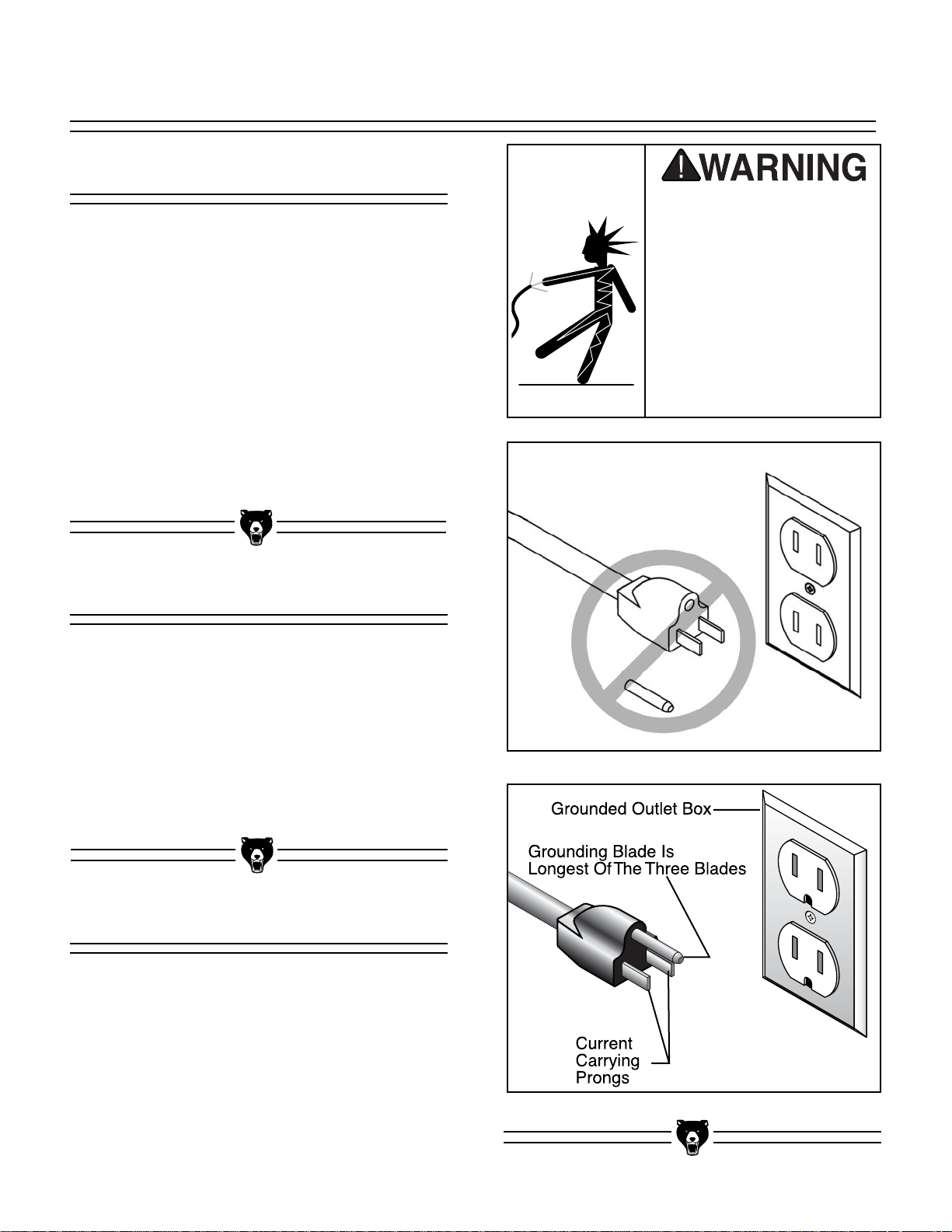
Grounding
This equipment must be
grounded. Verify that any
existing electrical outlet
and circuit you intend to
plug into is actually
grounded. Under no circumstances should the
grounding pin from any
three-pronged plug be
removed. Serious injury
may occur.
In the event of an electrical short, grounding
reduces the risk of electric shock by providing
electric current a path of least resistance. This
tool is equipped with a power cord having an
equipment-grounding conductor as shown in
Figure 1B. The outlet must be properly installed
and grounded in accordance with all local codes
and ordinances.
The Model G5979 is wired for 110V operation
only. The
1
⁄2 H.P. motor will safely draw 4 amps at
110V. If you operate this machine on any circuit
that is already close to its capacity, it might blow
a fuse or trip a circuit breaker. However, if an
unusual load does not exist and a power failure
still occurs, contact a qualified electrician or our
service department.
Figure 1B. Typical 110V plug and outlet.
Figure 1A. Do not remove grounding pin.
Page 8

-6- G5979 Wood Lathe
SECTION 3: INTRODUCTION
We are proud to offer the Grizzly Model G5979
Wood Lathe. The Model G5979 is part of a growing Grizzly family of fine woodworking machinery.
When used according to the guidelines set forth in
this manual, you can expect years of trouble-free,
enjoyable operation and proof of Grizzly’s commitment to customer satisfaction.
The Model G5979 is a 10 speed, swivel-head
wood lathe capable of a wide variety of turning
operations. This lathe also features a cast iron
bed, outboard tool rest, quick-release head and
tailstock, 12" swing over bed, 35
1
⁄2" between cen-
ters, 6" faceplate and #2 Morse Taper.
A number of chisels, gouges, faceplates and
accessories for the Model G5979 are available
through the Grizzly catalog.
We are also pleased to provide this manual with
the Model G5979. It was written to guide you
through assembly, review safety considerations,
and cover general operating procedures. It represents our effort to produce the best documentation possible. If you have any comments regarding this manual, please write to us at the address
below:
Grizzly Industrial, Inc.
C
/O Technical Documentation
P.O. Box 2069
Bellingham, WA 98227-2069
Most importantly, we stand behind our machines.
If you have any service questions or parts
requests, please call or write us at the location
listed below.
Grizzly Industrial, Inc.
1203 Lycoming Mall Circle
Muncy, PA 17756
Phone: (570) 546-9663
Fax: (800) 438-5901
E-Mail: techsupport@grizzly.com
Web Site: http://www.grizzly.com
The specifications, drawings, and photographs
illustrated in this manual represent the Model
G5979 as supplied when the manual was prepared. However, owing to Grizzly’s policy of continuous improvement, changes may be made at
any time with no obligation on the part of Grizzly.
Whenever possible, though, we send manual
updates to all owners of a particular tool or
machine. Should you receive one, we urge you to
insert the new information with the old and keep it
for reference.
Commentary
Read the manual before
assembly and operation. Become familiar
with the machine and its
operation before beginning any work. Serious
personal injury may
result if safety or operational information is not
understood or followed.
Page 9

G5979 Wood Lathe -7-
Unpacking
If moving this machine
up or down stairs, the
machine must be dismantled and moved in
smaller pieces. Make
sure floor and stair
structures are capable of
supporting the combined weight of the
machine parts and the
people moving them.
The Model G5979 is shipped from the manufacturer in a carefully packed carton. If you discover
the machine is damaged after you’ve signed for
delivery, immediately call Customer Service for
advice.
When you are completely satisfied with the condition of your shipment, you should inventory its
parts in the next section.
The G5979 represents a
load of 190 pounds.
Seek assistance before
beginning assembly.
Some metal parts may
have sharp edges on
them after they are
formed. Please examine
the edges of all metal
parts before handling
them. Failure to do so
could result in injury.
Page 10
-8- G5979 Wood Lathe
NOTICE
A full parts list and breakdown can be found
toward the end of this manual. For easier
assembly, or to identify specific parts,
please refer to the detailed illustrations at
the end of the manual.
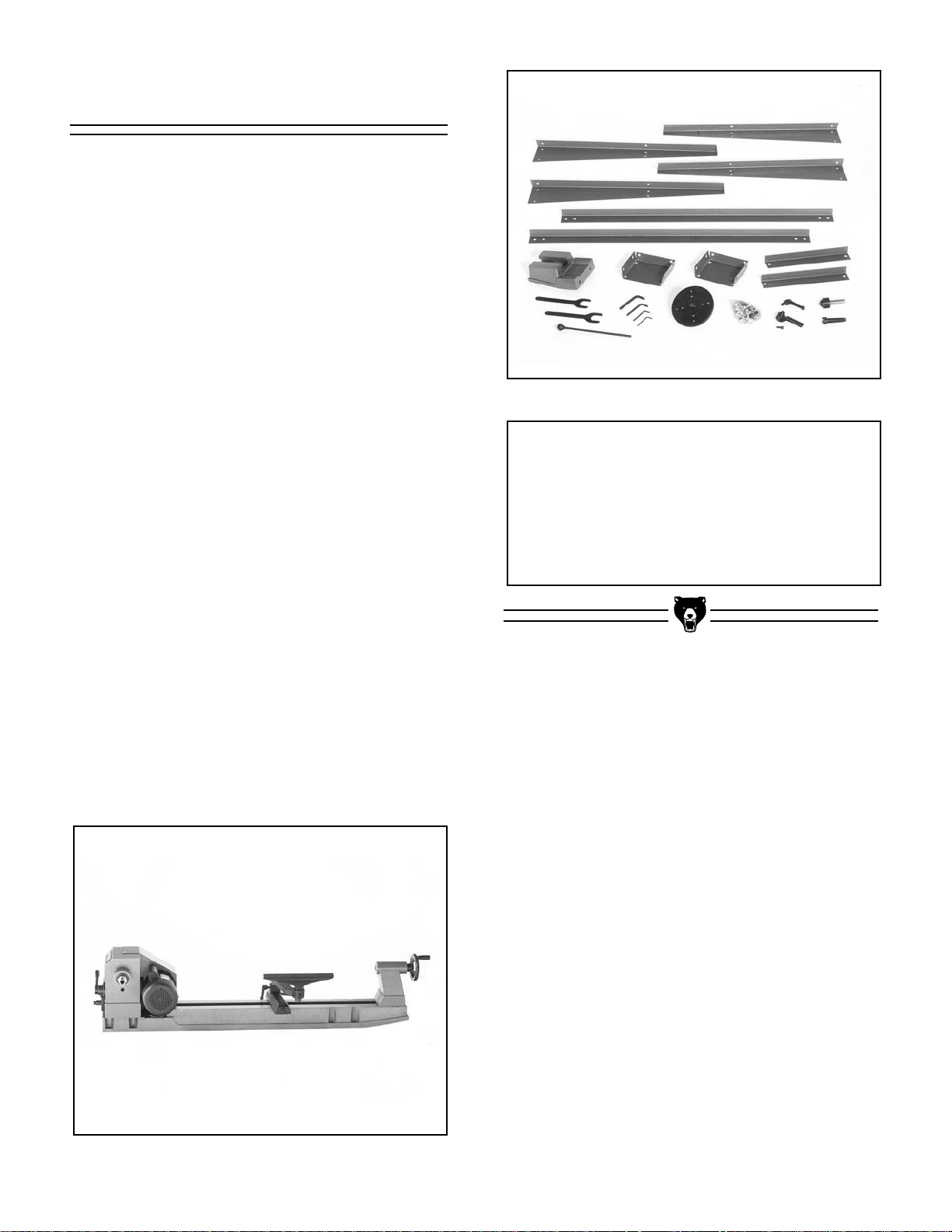
Figure 3. Parts layout.
Piece Inventory
After all the parts have been removed from the
carton, you should have:
• Lathe Unit
• Extension Bed
• Rear Legs (2)
• Front Legs (2)
• Long Leg Supports (2)
• Top Leg Plates (2)
• 4" Faceplate
• Live Center
• Spur Center
• Lock Handle
• Headstock Lock Handle
(w/Spring and Cap Screw)
• 3, 4, 6 and 8mm Allen
®
Wrenches
• Push Rod
• 32mm Open End Wrench (2)
• Hardware Bag
- M8-1.25 x 10 Carriage Bolts (24)
- M8-1.25 Hex Bolts (32)
- M8 Flat Washer (24)
- M8-1.25 x 35 Cap Screws (8)
- M8 Lock Washers (8)
- M10-1.5 x 25 Cap Screws (2)
- M10 Lock Washers (2)
In the event that any nonproprietary parts are
missing (e.g. a nut or a washer), we would be glad
to replace them, or for the sake of expediency,
replacements can be obtained at your local hardware store.
Figure 2. Lathe unit.
Page 11

G5979 Wood Lathe -9-
Hardware Recognition Chart
Use this chart to match up
hardware pieces during the
assembly process!
#
10
Lock
Nut
Wing
Nut
S
A
W
D
I
A
R
E
H
M
E
T
⁄8''
E
R
5
1
⁄4''
5
⁄16''
3
⁄8''
7
⁄16''
1
⁄2''
5
⁄8''
MEASURE BOLT DIAMETER BY PLACING INSIDE CIRCLE
4mm
6mm
8mm
10mm
12mm
LINES ARE 1MM APART
16mm
Thumb
Screw
Cap
Screw
Setscrew
Washer
5mm
10mm
15mm
20mm
25mm
30mm
35mm
40mm
45mm
50mm
55mm
60mm
65mm
70mm
75mm
Phillips
Head
Screw
Carriage
Bolt
Hex
Head
Bolt
Lock
Washer
1
⁄4''
3
⁄8''
1
⁄2''
5
⁄8''
⁄16'' INCH APART
1
LINES ARE
Countersunk
Phillips
Head
Screw
Flange
Bolt
Phillips
Head
Hex
Bolt
Hex
Nut
5
⁄16''
7
⁄16''
9
⁄16''
3
⁄4''
7
⁄8''
1''
1
1
⁄4''
1
⁄2''
1
3
⁄4''
1
2
1
⁄4''
2
1
⁄2''
2
3
⁄4''
2
3
Slotted
Screw
E
H
S
A
W
Button
Head
Screw
Phillips
A
S
W
E
H
Head
Sheet
Metal
Screw
S
D
I
A
M
R
S
A
S
H
W
H
A
E
E
W
S
A
R
E
H
12mm
W
R
10mm
D
8mm
E
T
E
R
D
I
A
R
M
E
E
H
T
S
E
A
R
W
D
I
A
M
4mm
E
T
E
R
D
I
A
R
M
E
E
H
T
S
E
A
R
W
I
A
M
6mm
E
T
E
R
WASHERS ARE MEASURED BY THE INSIDE DIAMETER
D
I
A
R
M
E
T
⁄16''
1
⁄2''
R
7
R
E
A
W
H
S
D
D
⁄16''
3
R
E
A
H
S
E
A
I
D
⁄8''
5
W
R
1
A
I
A
D
⁄16''
⁄4''
W
R
E
H
S
A
#
10
M
I
D
W
E
R
E
T
E
R
M
E
T
E
R
A
M
E
T
E
R
I
A
M
E
T
E
R
I
A
M
E
T
E
R
D
I
A
M
E
T
E
R
9
R
E
H
A
W
H
S
Page 12

-10- G5979 Wood Lathe
Clean Up
The unpainted surfaces are coated with a waxy oil
to protect them from corrosion during shipment.
Remove this protective coating with a solvent
cleaner or citrus-based degreaser such as
Grizzly’s G7895 Degreaser. Avoid chlorine-based
solvents as they may damage painted surfaces
should they come in contact. Always follow the
usage instructions on the product you choose for
clean up.
Do not smoke while using
solvents. A risk of explosion or fire exists and may
result in serious personal
injury.
Do not use gasoline or
other petroleum-based
solvents. They have low
flash points which make
them extremely flammable. A risk of explosion
and burning exists if
these products are
used. Serious personal
injury may occur if this
warning is ignored.
Many of the solvents
commonly used to clean
machinery can be toxic
when inhaled or ingested. Always work in wellventilated areas far from
potential ignition sources
when dealing with solvents. Use care when disposing of waste rags and
towels to be sure they do
not create fire or environmental hazards.
Site Considerations
FLOOR LOAD
Your Model G5979 represents a moderate weight
load in a small footprint. Most commercial or
home shop floors should be sufficient to carry the
weight of the Model G5979. If you question the
strength of your floor, you can opt to reinforce it.
Ensure that the stand or bench you use with the
Model G5979 is capable of supporting the
machine.
WORKING CLEARANCES
Working clearances can be thought of as the distances between machines and obstacles that
allow safe operation of every machine without limitation. Consider existing and anticipated machine
needs, size of material to be processed through
each machine, and space for auxiliary stands
and/or work tables. Also, consider the relative
position of each machine to one another for efficient material handling. Be sure to allow yourself
sufficient room to safely run your machines in any
foreseeable operation and keep dust collection
hoses off the floor and out of the way.
LIGHTING AND OUTLETS
Lighting should be bright enough to eliminate
shadows and prevent eye strain. Electrical circuits
should be dedicated or large enough to handle
combined motor amp loads. Outlets should be
located near each machine so power or extension
cords are not obstructing high-traffic areas. Be
sure to observe local electrical codes for proper
installation of new lighting, outlets, or circuits.
Make your shop “child
safe.” Ensure that your
workplace is inaccessible
to youngsters by closing
and locking all entrances
when you are away. Never
allow visitors in your shop
when assembling, adjusting or operating equipment.
Page 13

G5979 Wood Lathe -11-
SECTION 4: ASSEMBLY
Beginning Assembly
Most of your Model G5979 has been assembled
at the factory, but some parts must be assembled
or installed after delivery. We have organized the
assembly process into steps. Please follow along
in the order presented here.
TOOLS REQUIRED: Metric hex key set,
adjustable wrench, Phillips and flat screwdriver.
1. Attach a front and rear vertical leg to the top
plate using the
1
⁄4"-20 x 3⁄8" carriage bolts, 1⁄4"
flat washers and
1
⁄4" nuts. Position the top
plate so that it fits inside the legs.
2. Repeat the previous step with the other two
vertical legs.
3. Attach the two long horizontal supports to
each of the vertical leg assemblies using the
1
⁄4"-20 x 3⁄8" carriage bolts, 1⁄4" flat washers
and
1
⁄4" nuts.
4. Attach the two short horizontal supports to
each of the vertical leg assemblies using the
1
⁄4"-20 x 3⁄8" carriage bolts, 1⁄4" flat washers
and
1
⁄4" nuts.
5. Place the stand on a level surface and tight-
en all the nuts using a 14mm wrench.
Stand
Figure 4. Stand assembled.
Disconnect power to the
machine when performing any maintenance,
assembly or adjustments. Failure to do this
may result in serious
personal injury.
Keep loose clothing
rolled up and out of the
way of machinery and
keep hair pulled back.
Wear safety glasses during the entire assembly
process. Failure to comply may result in serious
personal injury.
Some metal parts may
have sharp edges on
them after they are
formed. Please examine
the edges of all metal
parts before handling
them. Failure to do so
could result in injury.
!
Page 14

-12- G5979 Wood Lathe
1. Carefully place the lathe unit on the stand
with the help of another person. Inspect the
stand to make sure all the braces and legs
are still secure.
2. Align the mounting hole in the top plates with
those on each end of the bed casting.
3. Attach the lathe unit to the stand using the
M8-1.25 x 35 cap screws, M8 flat washers
and M8-1.25 nuts as shown in Figure 5.
Securely tighten the cap screws.
Lathe To Stand
Figure 5. Attaching lathe unit to stand.
Do not attempt to lift the
lathe onto the stand by
yourself. Seek the assistance of another person.
We highly recommend mounting your Model
G5979 to the floor. Doing so will eliminate any
possibility of the lathe becoming unbalanced and
tipping over. The lathe will also produced better
results because there will be less vibration from
the machine. To mount the lathe to the floor:
Wooden Floor:
Use
1
⁄4" lag screws with flat washers. Be certain
the floor is stable and level. Drill pilot holes into
the floor and be careful not to tighten the lag bolts
too much or the hole may become stripped out.
Concrete Floor:
Mounting the lathe to a concrete floor involves the
use of stud anchors or some other similar fastener. Once the location is selected, drill the anchor
holes into the concrete floor using a hammer drill
and masonry bit. Be sure to follow the directions
of the anchoring system you have chosen.
Once the lathe is secured to the floor, check to
make sure it is still level and all the mounting bolts
are secure. Shim if needed.
Floor Mounting
Page 15

G5979 Wood Lathe -13-
The headstock can be locked into position using
the supplied locking handle. To install this handle:
1. Locate the handle, spring and special screw.
2. Slide the spring over the special screw. Push
the screw through the locking handle and
thread it into the locking clamp located on the
side of the headstock.
3. The locking handle is designed so that it can
be tightened down and then turned out of the
way of the operator. To tighten down the
handle, push in and turn clockwise.
Releasing the handle will disengage the
threaded shaft, allowing you to reposition the
lever handle out of the way. To release the
lock handle, push it in and turn counterclockwise.
Headstock Lock
Figure 7. Attaching the headstock lock handle.
2. Press it into the headstock spindle.
To remove the spur center:
1. Insert the push-out rod into the headstock
spindle hole opposite the end of the spur center.
2. A firm push should release the spur center.
You may have to tap on the end of the push
rod with a rubber mallet. Be sure to hold the
spur center before releasing it so it will not fall
on the floor.
The spur center is a M.T. #2. To install the spur
center:
1. Make certain the spur center is clean and free
of dirt or grease.
Spur Center
Figure 8. Installing the spur center.
Figure 9. Removing the spur center.
Page 16

-14- G5979 Wood Lathe
The faceplate is used when turning plates, bowls
and vases. The headstock spur must be removed
before installing the faceplate. To install the faceplate:
1. Remove the headstock spur using the push
rod.
2. Using two wrenches, thread on and tighten
the faceplate/workpiece assembly onto the
threaded spindle. Be sure to secure the faceplate tightly with two wrenches.
Faceplate
Figure 10. Attaching the faceplate.
The extension bed mounts to the left hand side of
the main lathe bed. To attach the extension bed:
1. Align the mounting holes of the extension
bed and the main lathe bed.
2. Using the M10-1.5 x 25 cap screws and M10
lock washers, attach the extension bed.
3. Be sure to securely tighten the cap screws.
The extension bed does not have to be perfectly level.
Extension Bed
Figure 11. Attaching extension table.
Page 17

G5979 Wood Lathe -15-
SECTION 5: ADJUSTMENTS
Disconnect power to the
machine when performing any maintenance,
assembly or adjustments. Failure to do this
may result in serious
personal injury.
Wear safety glasses
during the entire adjustment process. Failure to
comply may result in
serious personal injury.
Keep loose clothing
rolled up and out of the
way of machinery and
keep hair pulled back.
The headstock has 5 preset positions: 0° for general spindle turning; 60°, 90° and 120° when doing
faceplate turnings where the workpiece extends
below the level of the lathe/extension bed; and
180° when doing faceplate turning where the
workpiece edge does not extend below the edge
of the lathe/extension bed. To set the headstock
to the desired degree:
1. Loosen the lock handle by turning counter-
clockwise one full revolution.
2. Pull out on the headstock release knob and
rotate the headstock clockwise to the desired
setting. The headstock will be fixed into position when it clicks into one of the 5 preset
positions.
3. Tighten the lock handle that was loosened in
the first step. Do not attempt to lock the
headstock into a position other than the 5
presets.
Headstock
Figure 12. Adjusting headstock.
The tailstock can be moved along the length of
the lathe bed. The tailstock barrel holds the live
center, which can be adjusted up to 2
1
⁄2" from the
tailstock housing. To adjust the tailstock and tailstock spindle:
1. Loosen the tailstock lock handle by lowering
it and slide the tailstock to the desired position along the lathe bed. Retighten the tailstock lock handle by lifting it. The lock handle
mechanism can be adjusted by tightening or
loosening the large hex nut under the tailstock.
2. To adjust the tailstock barrel, loosen the spin-
dle lock handle.
3. Rotate the tailstock spindle handwheel until
the desired position is achieved. Retighten
the tailstock spindle lock handle.
4. To remove the live center from the tailstock
spindle, use the push-out rod inserted
through the hollow center of the tailstock
spindle.
Tailstock
!
Page 18

-16- G5979 Wood Lathe
Figure 13. Tailstock assembly.
Figure 14. Removing live center.
Tool Rest
Figure 15. Tool rest assembly.
The tool rest can be used with or without the
extension arm. To adjust the tool rest:
1. To adjust the main base along the bed,
loosen the lock lever and slide into the
desired position. Retighten the lock lever.
2. When using the extension arm, make the
necessary adjustments using the lock levers
and adjusting the extension arm. Re-tighten
the lock levers.
3. Make sure there is adequate clearance
between the workpiece and the tool rest. Test
by hand-turning the workpiece before turning
the lathe on.
Barrel Lock Handle
Tailstock Lock Handle
Tool Rest Lock Handles
Page 19

G5979 Wood Lathe -17-
SECTION 5: OPERATIONS
Once assembly is complete and adjustments are
done to your satisfaction, you are ready to test run
the machine.
Press the START button. Make sure that your finger is poised on the STOP button, just in case
there is a problem. The lathe should run smoothly, with little or no vibration or rubbing noises.
Strange or unnatural noises should be investigated and corrected before operating the machine
further.
If you cannot easily locate the source of an
unusual noise or vibration, contact our service
department for help.
Test Run
Wear a face shield during the test run and
operation of this wood
working lathe. Failure to
do so could result in
serious injury.
Keep loose clothing
rolled up and out of the
way of machinery and
keep hair pulled back.
Speed Selector
The variable speed selector allows the adjustment of the spindle R.P.M. The lathe should only
be turned ON when the speed is set at the lowest
R.P.M. The lathe must be ON to adjust the speed;
therefore, be sure to set the speed to the lowest
R.P.M. before turning OFF the machine.
Figure 16. Adjusting spindle speed.
Remember to choose the correct speed for
your particular turning project. As a general rule, the larger the workpiece diameter,
the slower the speed. Always start and stop
at the slowest speed.
The speed control lever can be turned to one of
ten fixed speeds. To set the speed:
1. Turn the lathe ON. Make sure that your finger
is poised on the STOP button, just in case
there is a problem. The lathe should run
smoothly, with little or no vibration or rubbing
noises. Strange or unnatural noises should
be investigated and corrected before operating the machine further. If you cannot easily
locate the source of an unusual noise or
vibration, contact our service department for
help.
2. Pull back on the lever handle and rotate to
the next higher speed as shown in
Figure 16
.
3. Turn the lever handle clockwise along the
index plate to increase the speed and counterclockwise to decrease the speed.
4. Remember to turn the lever handle to the
slowest R.P.M. before turning off the
machine.
Page 20

-18- G5979 Wood Lathe
To mount a workpiece between centers:
1. Locate the center point on both ends of the
workpiece by carefully drawing diagonal lines
from corner to corner. The point of intersection is the center of the work. Find the center
of a round workpiece by using a center finder
instrument.
2. When turning stock with a diameter greater
than 2", remove the corner length edges
shown in
Figure 17.
3. Line up the center of the spur center with the
center mark on the end of the workpiece.
While supporting the workpiece, slide the tailstock close to the end of the workpiece and
lock it into place.
4. Line up the live center with the center mark
on the other end of the workpiece. Turn the
handwheel to press the point of the live center into the workpiece.
5. Lock the tailstock in place.
Spindle Turning
Figure 17. Cross-section of turning stock.
Do not press too firmly or the bearings will
bind and overheat. Likewise, do not adjust
too loosely or the workpiece will spin off
the lathe. Use good judgement. Serious
personal injury could result if care is not
taken.
Wood Stock
D"
If measurement D" is greater
than 2", cut off the corners of
the wood stock.
Page 21

G5979 Wood Lathe -19-
1. Locate the center point of the workpiece by
carefully drawing diagonal lines from corner
to corner. The point of intersection is the center of the work. Find the center of round workpiece by using a center finder instrument.
2. Using 4 wood screws, attach the workpiece
as close to the center of the faceplate as possible. Make sure that the wood screws will
not interfere with the lathe chisels or intended cuts.
3. Adjust the headstock to the desired position
for the turning operation that you will be performing.
4. Attach the faceplate/workpiece assembly to
the headstock spindle using two wrenches.
Faceplate turning projects fall into two categories:
those that extend below the level of the
lathe/extension bed and those that do not. If your
project will rotate below the level of the
lathe/extension bed, you will need to rotate the
headstock to the 60° or 90° positions (discussed
further in Adjustments section). But if your pro-
ject does not extend below the lathe/extension
bed, it is safest to rotate the headstock 180° so
the project will rotate over the extension bed. This
allows the operator to stand directly in front of the
project and allows use of the tool rest without the
extension arm, thus, eliminating undue flexing of
the tool rest.
Faceplate Turning
Figure 19. Faceplate turning large projects.
Adjust the tool rest as close to the workpiece as
possible without actually coming into contact with
the workpiece. Test by hand-turning the workpiece before turning the lathe on. Ensure that the
lathe chisel is fully supported by the tool rest.
Support the lathe chisel on the tool rest with one
hand, while the other hand controls the chisel.
See Figure 21.
Tool Rest
Figure 21. Proper hand positioning.
Wear a face shield during the test run and
operation of this wood
working lathe. Failure to
do so could result in
serious injury.
Figure 20. Faceplate turning small projects.
Page 22

-20- G5979 Wood Lathe
SECTION 7: MAINTENANCE
Lubrication
V-Belt
All bearings are shielded and permanently lubricated. Simply leave them alone until they need to
be replaced. Do not lubricate them.
The end of the motor shaft has a lube fitting that
requires periodic lubrication. It is very important
not to over lube this fitting; otherwise, dirt and
debris will collect on the motor shaft, causing premature failure of the pulley mechanism. We recommend using a few shots of light spindle oil.
Inspect regularly for tension and wear. Check pulleys to ensure that they are properly aligned. See
pulley/V-belt sections for proper tension and pulley alignment procedures.
Regular periodic maintenance on your Model
G5979 will ensure its optimum performance.
Make a habit of inspecting your machine each
time you use it. Check for the following conditions
and repair or replace when necessary:
1. Loose mounting bolts.
2. Worn switch.
3. Worn or damaged cords and plugs.
4. Damaged V-belt.
5. Any other condition that could hamper the
safe operation of this machine.
General
Dust/Chip Removal
Saw dust and wood chips allowed to sit on cast
iron surfaces can trap moisture and cause rust.
Regularly wipe or blow sawdust and chip buildup
of of the lathe unit. This will help reduce the
chance of rust.
Rust
The nonpainted surfaces on the Model G5979
should be protected against rust and pitting.
Wiping the machine clean after every use ensures
that wood dust will not trap moisture against bare
metal surfaces.
Disconnect power to the
machine when performing any maintenance,
assembly or adjustments. Failure to do this
may result in serious
personal injury.
Wear safety glasses
during the entire maintenance process. Failure
to comply may result in
serious personal injury.
Keep loose clothing
rolled up and out of the
way of machinery and
keep hair pulled back.
!
Page 23

G5979 Wood Lathe -21-
The following pages contain general machine
data, parts diagrams/lists, a troubleshooting guide
and Warranty/Return information for your Model
G5979.
If you need parts or help in assembling your
machine, or if you need operational information,
we encourage you to call our Service Department.
Our trained service technicians will be glad to help
you.
If you have comments dealing specifically with
this manual, please write to our Bellingham,
Washington location using the address in Section
3: Introduction.
We have included some important safety measures that are essential to this machine’s operation. While most safety measures are generally
universal, Grizzly reminds you that each workshop is different and safety rules should be considered as they apply to your specific situation.
We recommend you keep a copy of our current
catalog for complete information regarding
Grizzly's warranty and return policy. If you need
additional technical information relating to this
machine, or if you need general assistance or
replacement parts, please contact the Service
Department listed in Section 3: Introduction.
Additional information sources are necessary to
realize the full potential of this machine. Trade
journals, woodworking magazines, and your local
library are good places to start.
SECTION 8: CLOSURE
The Model G5979 was specifically designed
for wood turning operations. DO NOT MODIFY AND/OR USE THIS MACHINE FOR ANY
OTHER PURPOSE. Modifications or
improper use of this tool will void the warranty. If you are confused about any aspect
of this machine, DO NOT use it until all your
questions have been answered or serious
personal injury may occur.
Like all power tools, there is danger associated with the Model G5979. Accidents
are frequently caused by lack of familiarity
or failure to pay attention. Use this tool
with respect and caution to lessen the
possibility of operator injury. If normal
safety precautions are overlooked or
ignored, serious personal injury may
occur.
Operating this equipment creates the potential for flying debris to cause eye injury.
Always wear safety glasses or goggles
when operating equipment. Everyday glasses or reading glasses only have impact
resistant lenses, they are not safety glasses.
Be certain the safety glasses you wear meet
the appropriate standards of the American
National Standards Institute (ANSI).
Page 24

-22- G5979 Wood Lathe
Customer Service #: (570) 546-9663 • To Order Call: (800) 523-4777 • Fax #: (800) 438-5901
MACHINE DATA
SHEET
Design Type ....................................................................................................Bench Model
Overall Dimensions:
Height ......................................................................................................................44''
Length ......................................................................................................................60''
Shipping Weight ...............................................................................................190 lbs.
Box Size ..................................................................................54
1
⁄2" L x 13" W x 14" H
Footprint ..................................................................................................43
1
⁄2" x 181⁄2"
Construction:
Bed ................................................................................................Cast Iron Flat Ways
Headstock........................................................................................................Cast Iron
Specifications:
Inboard Spindle Size, Type ........................................................................1'' x 8 T.P.I.
Tailstock ..............................................................................................................MT #2
Spindle ................................................................................................................MT #2
Range Of Speeds . . . . . . . . . . . . . . . . . . . . . . . . . . . . . . . . . . . . . . . . . . . . . . . . . . . . . . . . . . . . . . . . . . . . . . . . . . .10 @ 580 - 2850 R.P.M.
Swing ........................................................................................................................12''
Distance Between Centers ....................................................................................35
1
⁄2''
Swing Over Tool Rest . . . . . . . . . . . . . . . . . . . . . . . . . . . . . . . . . . . . . . . . . . . . . . . . . . . . . . . . . . . . . . . . . . . . . . . . . . . . . . . . . . . . . . . . . . . . . . . . . . . . . . . . . 9 ' '
Swivel Head ..............................................................................Stops @ 90° and 180°
Motor:
Type ............................................................................TEFC Capacitor Start Induction
Horsepower ........................................................................................................
1
⁄2 H.P.
Phase ⁄ Cycle ..........................................................................................Single ⁄ 60 Hz
Voltage ..................................................................................................................110V
Amperage..................................................................................................................4A
R.P.M.....................................................................................................................1720
Bearings ..............................................................Sealed and Permanently Lubricated
Accessories:
......................................................................................................................Tool Rest
........................................................................................................Live Rolling Center
..................................................................................................................Spur Center
....................................................................................................................Face Plate
..........................................................................Extension Bed for Out-Board Turning
......................................................................................................Tool Rest Extension
................................................................................................................Paddle Switch
Specifications, while deemed accurate, are not guaranteed.
GRIZZLY MODEL G5979 SWIVEL HEAD WOOD LATHE
Page 25

51
48-1
37
47
49
42
48
43
44A
55
41
40
50
46
2
3
45
36
37
41
24-1
24-3
38
24-2
39
37
24A
43
44A
4
6A
5
23
66
65-1
64
21
21-1
22
58
25
13
1
19
20
53-1
69
53
57A
34
31
33
63
32
71
Lube Fitting
30
11
28
26
18
59
7A
9
68
17A
8
35
10
27
12
52
15
16
Page 26

54-3
61
54-6
54-5
54-1
54-4
56
62
61
61
62
60
60
54-1
61
62
54-6
Page 27

G5979 Wood Lathe -25-
Ref# Part# Description
01 P5979001 HEADSTOCK
02 P5979002 DRIVE CENTER
03 P5979003 DISC
04 P5979004 SPINDLE
05 PK18M KEY 4 X 4 X 82
06A P5979006A BALL BEARING 80205Z
07A P5979007A BALL BEARING 80205Z
008 P5979008 SPRING
09 P5979009 BRACKET—SHIFTING LEVER
10 P6006 BALL BEARING 6006ZZ
11 P5979011 C-RING S-25
12 P5979012 SPINDLE PULLEY SET R & L
13 PVM23 V-BELT M-23 3L230
15 P5979015 C-RING S-24
16 P5979016 PIN-INJECTION
17A PLN09 LOCK NUT M12-1.75
18 P5979018 CLAMP LEFT
19 PB07M HEX BOLT M8-1.25 X 25
20 P5979020 RACK
21 P5979021 GEAR ASSEMBLY
21-1 PS09M PHLP HD SCR M5-.8 X 10
22 P5979022 CLAMP RIGHT
23 P5979023 SPECIAL SCREW
24A P5979024A SHAFT
24-1 P5979024-1 SPRING
24-2 P5979024-2 LOCK HANDLE
24-3 P5979024-3 SPECIAL CAP SCREW
25 P5979025 WRENCH
26 P5979026 C-RING S-16
27 P5979027 SLEEVE
28 P5979028 SPRING
30 P5979030 MOTOR PULLEY SET, L & R
31 PS09M PHLP HD SCR M5-.8 X 10
32 PK18M KEY 4 x 4 x 82
33 P5979033
1
⁄2 H.P. MOTOR
34 P5979034 MOTOR COVER
35 P5979035 ANGULAR SETTING ASSEMBLY
36 P5979036 TOOL REST
37 P5979037 HANDLE ASSEMBLY
38 P5979038 EXTENSION TOOL REST
Ref# Part# Description
39 P5979039 TOOL REST BODY
40 P5979040 ECCENTRIC ROD
41 PR08M EXT RETAINING RING 19MM
42 P5979042 SPECIAL SCREW
43 P5979043 CLAMP
44A P5979044A HEX NUT M18-2.5
45 P5979045 CENTER
46 P5979046 TAIL SPINDLE
47 P5979047 TAILSTOCK SCREW
48 P5979048 TAILSTOCK
48-1 PPSS25M SET SCREW M6-1 X 20
49 P5979049 HANDWHEEL
50 P5979050 LOCK HANDLE-TAILSTOCK
51 P5979051 SPECIAL BOLT
52 P5979052 EXTENSION BED
53 PSB64M CAP SCREW M10-1.5 X 25
53-1 PLW06M LOCK WASHER 10MM
54-1 P5979054-1 STAND LEG, LEFT
54-3 P5979054-3 STAND UPPER COVER
54-4 P5979054-4 STAND LONG-CROSS SUPPORT
54-5 P5979054-5
STAND SHORT-CROSS SUPPORT
54-6 P5979054-6 STAND LEG, RIGHT
55 P5979055 BED
56 PSB11M CAP SCREW M8-1.25 x 16
57A PSW08 SWITCH 110V WITH KEY
58 PS21M PHLP HD SCR M4-.7 X 15
59 P5979059 PLASTIC JAM NUT M20 X 1.5
60 PCB02M CARRIAGE BOLT M8-1.25 x 10
61 PW01M FLAT WASHER 8MM
62 PN03M HEX NUT M8-1.25
63
PWRCRD110L POWER CORD 110V, LONG W/PLUG
64 P5979064 LOGO LABEL
65-1 P5979065-1 GRIZZLY ID/WARNING LABEL
66 P5979066 SPEED LABEL
68 P5979068 SWITCH BOX
69 P5979069 SWITCH FIXING PLATE
71 P5979071 MOTOR POWER WIRE
Page 28

-26- G5979 Wood Lathe
Grizzly Industrial, Inc. warrants every product it sells for a period of 1 year to the original purchaser from
the date of purchase. This warranty does not apply to defects due directly or indirectly to misuse, abuse,
negligence, accidents, repairs or alterations or lack of maintenance. This is Grizzly’s sole written warranty
and any and all warranties that may be implied by law, including any merchantability or fitness, for any particular purpose, are hereby limited to the duration of this written warranty. We do not warrant or represent
that the merchandise complies with the provisions of any law or acts unless the manufacturer so warrants.
In no event shall Grizzly’s liability under this warranty exceed the purchase price paid for the product and
any legal actions brought against Grizzly shall be tried in the State of Washington, County of Whatcom.
We shall in no event be liable for death, injuries to persons or property or for incidental, contingent, special, or consequential damages arising from the use of our products.
To take advantage of this warranty, contact us by mail or phone and give us all the details. We will then
issue you a “Return Number,” which must be clearly posted on the outside as well as the inside of the carton. We will not accept any item back without this number. Proof of purchase must accompany the merchandise.
The manufacturers reserve the right to change specifications at any time because they constantly strive to
achieve better quality equipment. We make every effort to ensure that our products meet high quality and
durability standards and we hope you never need to use this warranty.
Please feel free to write or call us if you have any questions about the machine or the manual.
Thank you again for your business and continued support. We hope to serve you again soon.
WARRANTY AND RETURNS
Page 29

G5979 Wood Lathe -27-
10. Which benchtop tools do you own? Check all that apply.
___1" x 42" Belt Sander ___6" - 8" Grinder
___5" - 8" Drill Press ___Mini Lathe
___8" Table Saw ___10" - 12" Thickness Planer
___8" - 10" Bandsaw ___Scroll Saw
___Disc/Belt Sander ___Spindle/Belt Sander
___Mini Jointer
___Other__________________________________________________
11. How many of the machines checked above are Grizzly? ____________
12. Which portable/hand held power tools do you own? Check all that apply.
___Belt Sander ___Orbital Sander
___Biscuit Joiner ___Palm Sander
___Circular Saw ___Portable Planer
___Detail Sander ___Saber Saw
___Drill/Driver ___Reciprocating Saw
___Miter Saw ___Router
___Other__________________________________________________
13. What machines/supplies would you like Grizzly Industrial to carry?
__________________________________________________________
__________________________________________________________
14. What new accessories would you like Grizzly Industrial to carry?
__________________________________________________________
__________________________________________________________
15. What other companies do you purchase your tools and supplies from?
__________________________________________________________
__________________________________________________________
16. Do you think your purchase represents good value?
___Yes ___No
17. Would you recommend Grizzly Industrial to a friend?
___Yes ___No
18. Would you allow us to use your name as a reference for Grizzly customers
in your area? Note: We never use names more than three times.
___Yes ___No
19. Comments:_________________________________________________
__________________________________________________________
__________________________________________________________
__________________________________________________________
__________________________________________________________
1. How did you learn about us?
___Advertisement ___Friend
___Catalog ___Card Deck
___World Wide Web
___Other__________________________________________________
2. Which of the following magazines do you subscribe to.
___American Woodworker ___Practical Homeowner
___Cabinetmaker ___Shop Notes
___Family Handyman ___Today’s Homeowner
___Fine Homebuilding ___WOOD
___Fine Woodworking ___Wooden Boat
___Home Handyman ___Woodshop News
___Journal of Light Construction ___Woodsmith
___Old House Journal ___Woodwork
___Popular Mechanics ___Woodworker
___Popular Science ___Woodworker’s Journal
___Popular Woodworking ___Workbench
___Other__________________________________________________
3. Which of the following woodworking/remodeling shows do you watch?
___Backyard America ___The New Yankee Workshop
___Home Time ___This Old House
___The American Woodworker ___Woodwright’s Shop
___Other__________________________________________________
4. What is your annual household income?
___$20,000-$29,999 ___$60,000-$69,999
___$30,000-$39,999 ___$70,000-$79,999
___$40,000-$49,999 ___$80,000-$89,999
___$50,000-$59,999 ___$90,000 +
5. What is your age group?
___20-29 ___50-59
___30-39 ___60-69
___40-49 ___70 +
6. How long have you been a woodworker?
___0 - 2 Years ___8 - 20 Years
___2 - 8 Years ___20+ Years
7. How would you rank your woodworking skills?
___Simple ___Advanced
___Intermediate ___Master Craftsman
8. What stationary woodworking tools do you own? Check all that apply.
___Air Compressor ___Panel Saw
___Band Saw ___Planer
___Drill Press ___Power Feeder
___Drum Sander ___Radial Arm Saw
___Dust Collector ___Shaper
___Horizontal Boring Machine ___Spindle Sander
___Jointer ___Table Saw
___Lathe ___Vacuum Veneer Press
___Mortiser ___Wide Belt Sander
___Other__________________________________________________
9. How many of your woodworking machines are Grizzly? _____________
Name ____________________________________________________________________________________
Street ____________________________________________________________________________________
City ______________________________________________________________State________Zip_________
Phone Number_______________________E-Mail_______________________FAX________________________
MODEL # G5979 Wood Lathe Order #______________________________________________
The following information is given on a voluntary basis. It will be used for marketing purposes to help us develop better products and services. Of
course, all information is strictly confidential.
WARRANTY CARD
Page 30

FOLD ALONG DOTTED LINE
FOLD ALONG DOTTED LINE
GRIZZLY INDUSTRIAL, INC.
P.O. BOX 2069
BELLINGHAM, WA 98227-2069
Place
Stamp
Here
TAPE ALONG EDGES--PLEASE DO NOT STAPLE
Name_______________________________
Street_______________________________
City______________State______Zip______
Send a Grizzly Catalog to a friend:
Page 31

Page 32

 Loading...