

Page 1
MODEL G2905
1 HP ELECTRIC MOTOR
INSTRUCTIONS
For questions or help with this product contact Tech Support at (570) 546-9663 or [email protected]
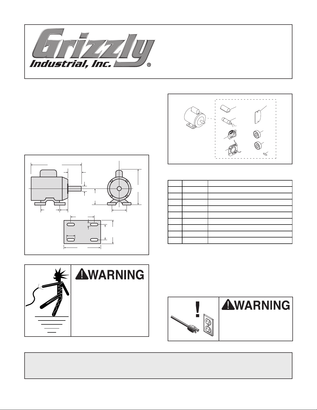
Model G2905 Specifications
Power .......................................................... 1 HP
Cycle............................................................60Hz
Voltage..................................................110/220V
Prewired
Amps
RPM
Phase
Class..................................................................E
...................................................... 110V
.................................................... 11.6/5.8A
............................................................. 1725
........................................................ Single
11.58"
2.16"
8.08"
3.55"
5
⁄8"
2.95" 2.77"
0.98"
4.92"
0.35"
6.30"
4.92"
3.94"
2.95"
Replaceable Parts
1
2
4
5
REF PART # DES CRIP TION
1 P2905001 S CAPACITOR COVER
2 P2905002 S CAPACITOR 300M 125V 1-3/4 X 3-3/8
3 P2905003 WIRING COVER PLATE
4 P2905004 CENTRIFUGAL SWITCH 1/2-1725
5 P2905005 CONTACT PLATE
6 P2905006 BALL BEARING 6202ZZ
7 P2905007 BALL BEARING 6203ZZ
8 P2905008 KEY 3/16 X 3/16 X 1-1/4
9 P2905009 R CAPACITOR COVER
10 P2905010 R CAPACITOR 30M 250V 1-3/8 X 2-3/8
3
6
7
8
Making Wire Connections
If you are unsure how to attach wires to terminals, DO NOT continue. Contact an electrician
for assistance. Connecting wires improperly may
Electrocution or fire could
result if this motor is not
grounded correctly or if
your wire connections do
not comply with local and
state codes. Ensure compliance by checking with a
qualified electrician!
COPYRIGHT © JUNE, 2012 BY GRIZZLY INDUSTRIAL, INC., REVISED JUNE, 2024 (LW)
NO PORTION OF THIS INSTRUCTION SHEET MAY BE REPRODUCED IN ANY SHAPE
OR FORM WITHOUT THE WRITTEN APPROVAL OF GRIZZLY INDUSTRIAL, INC.
(FOR MODELS MFD. SINCE 08/24) #KN15081 PRINTED IN TAI WA N
***Keep for Future Reference***
cause electrocution, fire, or a short.
Disconnect power when
replacing motor. Failure
to do this may result in
serious personal injury.
V2.06.24
Page 2
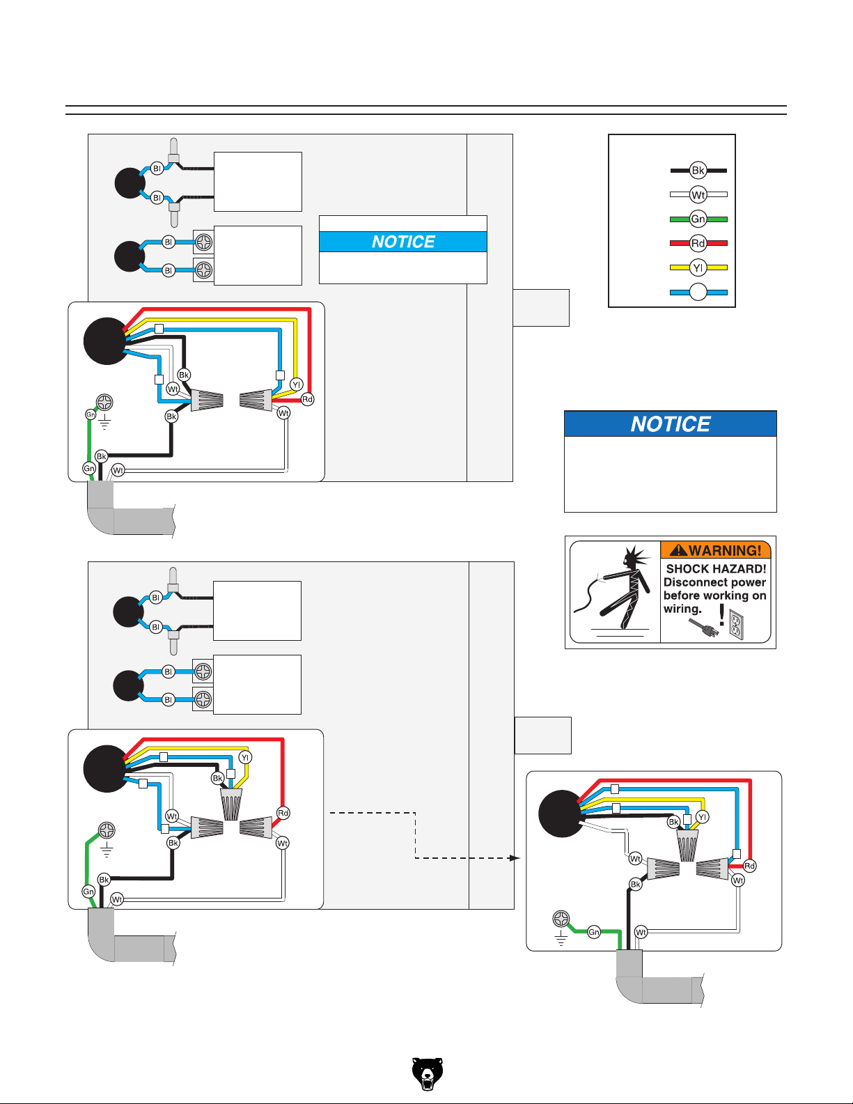
G2905 Wiring Diagram
Ground
Run
Capacitor
30 MFD
250 VAC
Start
Capacitor
300 MFD
125 VAC
5
6
5
110V
(PREWIRED)
110V MOTOR DIRECTION
To reverse motor direction,
switch wires #5 & #6.
The motor wiring shown here is
current at the time of printing, but it
may not match your motor. Always
use the wiring diagram inside the
motor junction box.
BLACK
WHITE
GREEN
RED
YELLOW
BLUE
Bl
COLOR KEY
Ground
Run
Capacitor
30 MFD
250 VAC
Start
Capacitor
300 MFD
125 VAC
220V
CLOCKWISE
220V
5
6
6
5
Ground
COUNTERCLOCKWISE
6
5
5
6
-2-
Model G2905 (Mfd. Since 08/24)
 Loading...