

Page 1

MODEL G0768Z
8" X 16" VARIABLE-
SPEED LATHE WITH DRO
MANUAL INSERT
Model G0768Z is an upgraded version of Model G0768 with an included X/Z-Axis DRO.
NOTE: The bed, saddle, and cross slide on this model have been specially machined to mount the DRO
scales. Thus, the DRO components included with this model cannot be easily retrofitted onto Model G0768.
: To reduce the risk of serious injury, you MUST read and understand this insert—and
the entire Model G0768 manual—BEFORE assembling, installing, or operating this machine!
If you have any further questions about this manual insert or the differences between the Model G0768 and
the Model G0768Z, contact our Technical Support at (570) 546-9663 or email techsupport@grizzly.com.
COPYRIGHT © JUNE, 2017 BY GRIZZLY INDUSTRIAL, INC.
WARNING: NO PORTION OF THIS MANUAL MAY BE REPRODUCED IN ANY SHAPE
OR FORM WITHOUT THE WRITTEN APPROVAL OF GRIZZLY INDUSTRIAL, INC.
(FOR MODELS MANUFACTURED SINCE 02/17) #KB18653 PRINTED IN CHINA
Page 2

G0768Z Unique Parts
109
128
129
130
131
131
132
133
134
134
135
136
149
151
152
134
135
136
420
421
G0768Z
B
A
Spindle Speed RPM
A B
100-2000
50-1000
To avoid high-speed starting, turn dial
to lowest position before starting.
M
50 1000
RPM
2000100
Specifications
Motor: 600W (3/4 HP), 110V, 1-Ph, 60 Hz, 10A
Swing Over Bed: 8-1/4"
Distance Between Centers: 15-3/4"
Swing Over Cross Slide: 4-5/8"
Spindle Speeds: 50 – 1000, 100 – 2000 RPM
Spindle Type: Intrinsic Back Plate
Spindle Bore: 0.787" (20mm)
Spindle Taper: MT#3
Tailstock Taper: MT#2
Tailstock Quill Travel: 2"
Maximum Tool Size: 3/8"
Cross Slide Travel: 3"
Compound Travel: 2-1/8"
Weight: 144 lbs.
Date
S/N
Mfd. for Grizzly in China
704
710
419
187
188
154
442
193
155
186
183
X
Y
Z
in
mm
192
190
185
mm
inch
191
196
zero
zero
zero
195
184
181
182
189
182
182
443
444
445
194
REF PART # DESCRIPTION REF PART # DESCRIPTION
154 P0768Z154 CROSS SLIDE 192 P0768Z192 FLAT WASHER 3MM, PLASTIC
155 P0768Z155 SADDLE 193 P0768Z193 DRO DISPLAY UNIT
181 P0768Z181 X-AXIS DRO SENSOR 194 P0768Z194 DRO POWER CORD 2W 18G 72" 1-15P
182 P0768Z182 CAP SCREW M3-.5 X 16 195 P0768Z195 Z-AXIS SENSOR CONNECTING PLATE
183 P0768Z183 X-AXIS MOUNTING PLATE 196 P0768Z196 HEX NUT M3-.5
184 P0768Z184 CAP SCREW M3-.5 X 20 419 P0768Z419 BED
185 P0768Z185 FLAT WASHER 3MM 442 P0768Z442 Z-AXIS SENSOR BRACKET 30 X 30 X 400
186 P0768Z186 SPACER 3 X 7 X 11, PLASTIC 443 P0768Z443 PHLP HD SCR M4-.7 X 12
187 P0768Z187 X-AXIS SENSOR BRACKET 9 X 29 X 182 444 P0768Z444 LOCK WASHER 4MM
188 P0768Z188 CAP SCREW M3-.5 X 6 445 P0768Z445 FLAT WASHER 4MM
189 P0768Z189 Z-AXIS DRO SENSOR 704 P0768Z704 VARIABLE SPEED LABEL
190 P0768Z190 Z-AXIS SENSOR MOUNTING BRACKET 710 P0768Z710 MACHINE ID LABEL
191 P0768Z191 SPACER 3 X 7 X 6, PLASTIC
-2-
Model G0768Z (Mfd. Since 02/17)
Page 3
DRO Components
Digital Readout
Model G0768Z features a magnetically mounted
DRO (see Figure 1) for X-axis (cross slide) and
Z-axis (carriage) travel.
Note: When placing the DRO, locate all cables so
they do not interfere with machine operation and
cannot be pinched by moving components.
Using the DRO
A. DRO displays current position of X-axis and
Z-axis in hundredths of a millimeter or thousandths of an inch. (Included Y-axis display
line is not used on G0768Z.)
B. "X" value displays total X-axis travel from
zero along cross slide.
C. "Z" value displays total Z-axis travel from
zero along lathe bed.
D. In/MM button allows users to toggle
measurement display in either inches or
millimeters.
E. ZERO buttons reset values at any point along
the axis to 0.00.
F. Green light indicates inches or millimeters.
G. Magnetic mount.
Figure 1. DRO magnetically mounted on lathe
headstock.
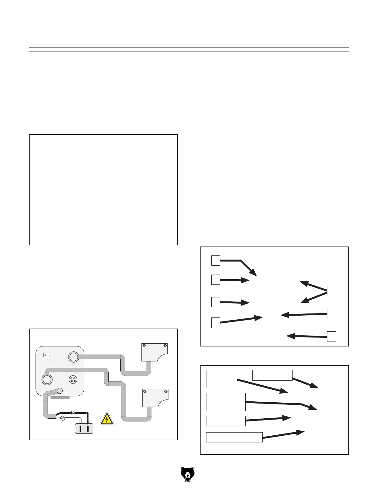
The X-axis and Z-axis scales are attached to
the cross slide and bed (respectively). Shielded
cables run from each sensor to plugs on the back
of the DRO (see Figure 2). The DRO connects
to a regular 110V power supply with a dedicated
power cord using a NEMA 1-15 plug.
DRO
(Viewed from behind)
CXM-3
POWER
X-Axis Port
Power
Cord
Port
Z-Axis Port
Y-Axis Port
(Not Used)
NEUTRAL
HOT
AW
110 VAC
1-15 Plug
Z-Axis Sensor
X-Axis Sensor
Figure 2. DRO wiring.
A
B
C
D
Figure 3. DRO controls and display.
ON/OFF
Z-Axis Port
Switch
Y-Axis Port
(Not Used)
X-Axis Port
DRO Power Cord
E
F
G
Model G0768Z (Mfd. Since 02/17)
Figure 4. DRO cable connections (rear).
-3-
Page 4

Page 5

MODEL G0768/G0769
8" X 16" VARIABLE-SPEED
LATHE & LATHE/MILL
OWNER'S MANUAL
(For models manufactured since 6/17)
Model G0768 Model G0769
COPYRIGHT © AUGUST, 2014 BY GRIZZLY INDUSTRIAL, INC. REVISED JUNE, 2018 (HE)
WARNING: NO PORTION OF THIS MANUAL MAY BE REPRODUCED IN ANY SHAPE
OR FORM WITHOUT THE WRITTEN APPROVAL OF GRIZZLY INDUSTRIAL, INC.
# BLTSDM16348 PRINTED IN CHINA
V3 . 0 6 .18
Page 6

This manual provides critical safety instructions on the proper setup,
operation, maintenance, and service of this machine/tool. Save this
document, refer to it often, and use it to instruct other operators.
Failure to read, understand and follow the instructions in this manual
may result in fire or serious personal injury—including amputation,
electrocution, or death.
The owner of this machine/tool is solely responsible for its safe use.
This responsibility includes but is not limited to proper installation in
a safe environment, personnel training and usage authorization,
proper inspection and maintenance, manual availability and comprehension, application of safety devices, cutting/sanding/grinding tool
integrity, and the usage of personal protective equipment.
The manufacturer will not be held liable for injury or property damage
from negligence, improper training, machine modifications or misuse.
Some dust created by power sanding, sawing, grinding, drilling, and
other construction activities contains chemicals known to the State
of California to cause cancer, birth defects or other reproductive
harm. Some examples of these chemicals are:
• Lead from lead-based paints.
• Crystalline silica from bricks, cement and other masonry products.
• Arsenic and chromium from chemically-treated lumber.
Your risk from these exposures varies, depending on how often you
do this type of work. To reduce your exposure to these chemicals:
Work in a well ventilated area, and work with approved safety equipment, such as those dust masks that are specially designed to filter
out microscopic particles.
Page 7

Table of Contents
INTRODUCTION ............................................... 3
Machine Description ...................................... 3
Contact Info.................................................... 3
Manual Accuracy ........................................... 3
Identification (G0768)..................................... 4
Identification (G0769)..................................... 5
Controls & Components ................................. 6
Headstock ...................................................................6
Carriage ....................................................................... 6
Tailstock ...................................................................... 7
End Gears, Pulleys, V-Belts ........................................7
Milling Headstock (G0769 Only) ................................. 8
G0768 Data Sheet ......................................... 9
G0769 Data Sheet ....................................... 11
SECTION 1: SAFETY ..................................... 13
Safety Instructions for Machinery ................ 13
Additional Safety for Metal Lathes ............... 15
Additional Safety for Mills/Drills ................... 16
Additional Lathe Chuck Safety..................... 17
SECTION 2: POWER SUPPLY ...................... 18
Availability .................................................................18
Full-Load Current Rating ...........................................18
110V Circuit Requirements .......................................18
Grounding & Plug Requirements ..............................19
Extension Cords ........................................................19
SECTION 3: SETUP ....................................... 20
Setup Overview............................................ 20
Unpacking .................................................... 20
Needed for Setup ......................................... 20
Inventory ...................................................... 21
Cleanup ........................................................ 22
Site Considerations ...................................... 23
Lifting & Placing ........................................... 24
Mounting ...................................................... 25
Leveling ........................................................ 26
Assembly ..................................................... 26
Test Run ...................................................... 27
Spindle Break-In .......................................... 29
Lathe Spindle Break-In ..............................................29
Mill Spindle Break-In (G0769 Only) ..........................29
Recommended Adjustments ........................ 30
SECTION 4: LATHE OPERATIONS .............. 31
Operation Overview ..................................... 31
Chuck & Faceplate Mounting....................... 32
Installation & Removal Device ..................... 32
Chuck Installation......................................... 32
Scroll Chuck Clamping ................................ 33
Changing Jaw Set ........................................ 34
4-Jaw Chuck ................................................ 35
Faceplate ..................................................... 36
Tailstock ....................................................... 37
Tailstock Quill Specs .................................................37
Positioning Tailstock .................................................37
Using Quill .................................................................37
Installing Tooling .......................................................38
Removing Tooling .....................................................38
Offsetting Tailstock ....................................................38
Aligning Tailstock to Spindle Centerline ....................39
Centers ........................................................ 41
Dead Centers ............................................................41
Mounting Dead Center in Spindle .............................41
Removing Center from Spindle .................................41
Mounting Center in Tailstock ....................................42
Removing Center from Tailstock ...............................42
Mounting Workpiece Between Centers .....................42
Steady Rest ................................................. 43
Follow Rest .................................................. 43
Compound Rest ........................................... 44
Four-Way Tool Post ..................................... 44
Installing Tool ............................................................44
Aligning Cutting Tool with Spindle Centerline ...........45
Manual Feed ................................................ 46
Carriage Handwheel .................................................46
Cross Slide Handwheel .............................................46
Compound Rest Handwheel .....................................46
Spindle Speed.............................................. 47
Determining Spindle Speed ......................................47
Setting Spindle Speed Range ...................................47
Setting Spindle Direction & Speed ............................47
Configuration Example ..............................................48
Understanding Gear Charts ......................... 49
Feed & Thread Charts Label .....................................49
How to Read the Feed Chart ....................................50
How to Read the Thread Charts ...............................51
End Gears .................................................... 52
Power Feed Configuration ........................................52
Primary Threading Configuration ..............................52
Secondary Threading Configuration .........................52
Configuring End Gears ..............................................53
Power Feed.................................................. 56
Power Feed Controls ................................................56
Setting Power Feed Rate ..........................................57
Threading ..................................................... 58
Headstock Threading Controls ..................................58
Apron Threading Controls .........................................59
Thread Dial ................................................................59
Thread Dial Chart ......................................................59
Page 8

SECTION 5: MILL OPERATIONS .................. 60
Operation Overview ..................................... 60
Removing Compound Rest .......................... 61
Removing Compound Rest ......................................61
Re-installing Compound Rest ..................................61
Headstock Movement .................................. 62
Raising/Lowering Headstock .....................................62
Tilting Headstock .......................................................62
Table Travel ................................................. 63
Carriage Handwheel (X-Axis) ....................................63
Cross Slide Handwheel (Y-Axis) ...............................63
Using Spindle Downfeed Controls ............... 64
Coarse Downfeed .....................................................64
Fine Downfeed ..........................................................64
Engaging Fine Downfeed Controls ...........................64
Installing/Removing Tooling ......................... 65
Installing Tooling .......................................................65
Removing Tooling .....................................................66
Spindle Speed.............................................. 67
Determining Spindle Speed ......................................67
Setting Spindle Speed ...............................................67
SECTION 6: ACCESSORIES ......................... 68
SECTION 7: MAINTENANCE ......................... 71
Schedule ...................................................... 71
Ongoing .....................................................................71
Daily, Before Operations ...........................................71
Daily, After Operations ..............................................71
Every 90 Hours of Operation ....................................71
Every 120 Hours of Operation ..................................71
Annually .....................................................................71
Cleaning/Protecting ...................................... 71
Lubrication ................................................... 72
Lubrication Frequency ...............................................72
Ball Oilers ..................................................................72
Leadscrew & Carriage Rack .....................................73
Bedways ....................................................................73
Feed Gearbox ...........................................................73
Cross Slide & Compound Slide .................................73
End Gears .................................................................74
Column Ways (G0769) ..............................................75
Quill Outside Surface ................................................75
Quill Rack .................................................................75
Z-Axis Leadscrew (G0769) .......................................76
Headstock Gears (G0769) ........................................76
Machine Storage .......................................... 77
Preparing Machine for Storage .................................77
Bringing Machine Out of Storage ..............................77
SECTION 8: SERVICE ................................... 78
Troubleshooting ........................................... 78
Motor & Electrical ......................................................78
Lathe Operation ........................................................79
Mill Operation ............................................................80
Tensioning & Replacing V-Belts .................. 81
Adjusting Backlash....................................... 82
Cross Slide ................................................................82
Adjusting Leadscrew End Play .................... 82
Adjusting Gibs .............................................. 83
Adjusting Cross Slide and Compound Slide Gibs .....83
Adjusting Z-Axis Way Gib .........................................84
Adjusting Half Nut ........................................ 84
Replacing Leadscrew Shear Pin.................. 85
Replacing Fuse ............................................ 85
Replacing Brushes ....................................... 86
Replacing Lathe Motor Brushes ................................86
Replacing Mill Motor Brushes (G0769) .....................87
SECTION 9: WIRING ...................................... 88
Wiring Safety Instructions ............................ 88
G0768 Wiring Overview ............................... 89
G0768 Wiring ............................................... 90
G0768 Wiring Photos ................................... 91
G0769 Wiring Overview ............................... 92
G0769 Wiring ............................................... 93
G0769 Wiring Photos ................................... 94
SECTION 10: PARTS ..................................... 95
Headstock .................................................... 95
Carriage Components & Accessories .......... 96
Apron ........................................................... 99
Gearbox ..................................................... 100
Bed & End Gears ....................................... 101
Tailstock ..................................................... 102
G0769 Mill Column .................................... 103
G0769 Mill Headstock ................................ 104
G0768 Labels & Cosmetics ....................... 106
G0769 Labels & Cosmetics ....................... 107
G0768 Electrical Component Diagram ...... 108
G0769 Electrical Component Diagram ...... 109
SECTION 11: APPENDIX ............................. 110
Threading & Feeding Chart ....................... 110
Thread Dial Chart ...................................... 110
WARRANTY & RETURNS ........................... 113
Page 9

INTRODUCTION
We are proud to provide a high-quality owner’s
manual with your new machine!
We
instructions, specifications, drawings, and photographs
in this manual. Sometimes we make mistakes, but
our policy of continuous improvement also means
that
you receive is
slightly different than shown in the manual
If you find this to be the case, and the difference
between the manual and machine leaves you
confused or unsure about something
check our
website for an updated version. W
current
manuals and
on our web-
site at
Alternatively, you can call our Technical Support
for help. Before calling, make sure you write down
the
from
the machine ID label (see below). This information
is required for us to provide proper tech support,
and it helps us determine if updated documentation is available for your machine.
We stand behind our machines! If you have questions or need help, contact us with the information
below. Before contacting, make sure you get the
serial number
machine ID label. This will help us help you faster.
We want your feedback on this manual. What did
you like about it? Where could it be improved?
Please take a few minutes to give us feedback.
Machine Description
The Model G0768 and G0769 share lathe features such as a 600 Watt (
variable-speed controls with digital RPM display,
high/low spindle speed ranges, 4" 3-jaw and
4-jaw chucks, a convenient quick-lock tailstock, a
4-way turret toolpost, steady and follow rests, and
reverse feed for cutting left-hand threads.
The Model G0769 additionally features a 600
Watt (
right head tilt, coarse and fine downfeed controls, Z-axis dovetailed ways for maximum precision, and a
table features T-slots for mounting a vise. The
lathe/mill selector switch also makes changing between lathe and milling modes easy.
Both machines can be mounted on a sturdy workbench, or the optional Model T26599 stand—with
cabinet space for storing tooling and accessories.
3
⁄4 HP) milling headstock motor, 45° left/
1
⁄2 " drill chuck. The cross slide
3
⁄4 HP) 110V DC motor,
Manual Accuracy
made every effort to be exact with the
sometimes the machine
.
,
e post
manual updates for free
www.grizzly.com.
Manufacture Date and Serial Number
Contact Info
and manufacture date from the
Grizzly Technical Support
1815 W. Battlefield
Springfield, MO 65807
Phone: (570) 546-9663
Email: techsupport@grizzly.com
Grizzly Documentation Manager
P.O. Box 2069
Bellingham, WA 98227-2069
Email: manuals@grizzly.com
Manufacture Date
Serial Number
Model G0768/G0769 (Mfd. Since 6/17)
-3-
Page 10

Identification (G0768)
To reduce your risk of
serious injury, read this
entire manual BEFORE
Become familiar with the names and locations of the controls and features shown below to better understand
the instructions in this manual.
On/Off Switch w/
Emergency Stop
Spindle Direction
Switch
Spindle
Speed
RPM
Display
Button
3-Jaw
Chuck
Steady
Rest
4-Way
Tool Post
Compound Rest
Handwheel
Tailstock
Spindle
Speed Dial
-4-
Feed
Direction
Dial
Carriage
Handwheel
Figure 1. Model G0768 identification.
Cross Slide
Handwheel
using machine.
Half Nut
Lever
Thread
Carriage
Lock
Model G0768/G0769 (Mfd. Since 8/15)
Dial
Page 11

Identification (G0769)
Become familiar with the names and locations of the controls and features shown below to better understand
the instructions in this manual.
Fine Downfeed
Handwheel
Vertical Travel
Lathe/Mill Selector
Switch
Spindle
Lock
Handwheel
On/Off Switch w/
Emergency Stop
Button
Spindle Direction
Switch
Spindle
Speed
RPM
Display
Spindle
Speed Dial
3-Jaw
Chuck
Steady
Rest
Vertical Travel
Lock Levers
Downfeed
Selector
Knob
Coarse
Downfeed
Handle
4-Way
Tool Post
Tailstock
Feed
Direction
Dial
Cross Slide
Handwheel
Carriage
Handwheel
Figure 2. Model G0769 identification.
Model G0768/G0769 (Mfd. Since 8/15)
Half Nut
Lever
Carriage
Lock
Thread
Dial
Compound Rest
Handwheel
-5-
Page 12

Controls &
To reduce your risk of
serious injury, read this
entire manual BEFORE
Components
E. ON/OFF Switch w/Emergency Stop Button:
When pressed, cuts power to motor and control panel. To reset, press front tab, lift switch
cover, and press green ON button. Cover
must be unlatched for machine to run.
F. Lathe/Mill Selector Switch (G0769 Only):
Used to select between lathe mode (1), or
mill mode (2).
using machine.
Refer to Figures 3–8 and the following descriptions to become familiar with the basic controls of
this machine.
Headstock
E
D
C
B
A
Figure 3. Control panel.
F
Carriage
I
H
G
Figure 4. Carriage controls.
G. Carriage Handwheel: Manually moves car-
riage left or right along bedway.
H. Cross Slide Handwheel: Moves cross slide
toward and away from workpiece.
I. 4-Way Tool Post: Holds up to four cutting
tools at once that can be individually indexed
to workpiece and quickly moved into position
when needed.
J
K
L
M
A. Feed Direction Dial: Used to select direction
of leadscrew rotation when spindle is rotating
in downward (F) direction. Used to switch
between right or left thread cutting.
B. Spindle Speed Dial: Controls spindle speed.
C. Spindle Speed RPM Display: Shows spin-
dle speed.
D. Spindle Direction Switch: Selects spindle
rotation direction.
-6-
J. Cross Slide Table (G0769 Only): Supports
workpieces for milling/drilling operations.
Includes T-slots for mounting milling vises or
other fixtures.
K. Compound Rest Handwheel: Moves tool
toward and away from workpiece at preset
compound angle.
L. Thread Dial: Indicates when to engage the
half nut during threading operations.
M. Half Nut Lever: Engages/disengages half
nut for power feeding and threading operations.
Model G0768/G0769 (Mfd. Since 6/17)
Page 13

Tailstock End Gears, Pulleys, V-Belts
U. End Gears: The configuration of the end
O
N
T
P
Q
R
S
gears controls the leadscrew speed for power
feeding, and inch and metric threading.
V. V-Belts: Transfer power from motor to idler
and spindle pulleys. The position of the top
V-belt on idler and spindle pulleys controls
spindle speed.
U
Figure 5. Tailstock controls.
N. Tailstock Quill: Uses an MT#2 taper to hold
centers or other tooling, features a scale on
top.
O. Tailstock Quill Lock Lever: Secures quill
position.
P. Tailstock Lock Lever: Secures tailstock in
position along bedway.
Q. Graduated Scale: Indicates quill movement
in increments of 0.001", with one full revolution equaling 0.04" of quill travel.
R. Quill Handwheel: Moves quill toward or
away from spindle.
S. Offset Scale: Indicates relative distance of
tailstock offset from spindle centerline.
T. Tailstock Offset Screws: Adjusts tailstock
offset left or right from spindle centerline (1 of
2).
V
Figure 6. End gears, V-belts, and pulleys.
Serious personal injury could occur if
you connect the machine to power before
completing the setup process. DO NOT
connect power until instructed to do so later
in this manual.
Model G0768/G0769 (Mfd. Since 6/17)
-7-
Page 14

Milling Headstock (G0769 Only)
X
AB
Y
AC
Z
AD
AA
Figure 7. Right side milling headstock controls.
X. Fine Downfeed Handwheel: Provides fine
control over vertical spindle travel to provide
Z-axis control when milling.
Y. Vertical Travel Lock Levers: Locks position
of headstock to column.
Z. Downfeed Selector Knob: Selects between
fine and coarse downfeed modes. Tighten to
engage fine downfeed. Loosen to use coarse
downfeed.
AA. Coarse Downfeed Handles: Moves spindle
down quickly when rotated and automatic
spring return brings spindle back up to top
when you release downward pressure on
handles. Typically used for drilling holes or
checking spindle positioning during setups.
Figure 8. Left side milling headstock controls.
AB. Vertical Handwheel: Raises and lowers
headstock for Z-axis control over spindle
positioning during setups.
AC. High/Low Gearbox Knob: Selects low range
"L" or high range "H" for spindle speed.
AD. Quill Lock Lever: Locks vertical position
of quill (or Z-axis) when tightened. Typically
used in conjunction with spindle downfeed
controls when milling.
-8-
Model G0768/G0769 (Mfd. Since 6/17)
Page 15

MACHINE DATA
SHEET
Customer Service #: (570) 546-9663 · To Order Call: (800) 523-4777 · Fax #: (800) 438-5901
MODEL G0768 8" X 16" VARIABLE‐SPEED LATHE
Product Dimensions:
Weight.............................................................................................................................................................. 144 lbs.
Width (side-to-side) x Depth (front-to-back) x Height........................................................................... 36 x 16 x 14 in.
Footprint (Length x Width)............................................................................................................... 31-1/2 x 10-1/2 in.
Shipping Dimensions:
Type.......................................................................................................................................................... Wood Crate
Content........................................................................................................................................................... Machine
Weight.............................................................................................................................................................. 166 lbs.
Length x Width x Height....................................................................................................................... 36 x 19 x 17 in.
Must Ship Upright................................................................................................................................................... Yes
Electrical:
Power Requirement........................................................................................................... 110V, Single-Phase, 60 Hz
Full-Load Current Rating........................................................................................................................................ 10A
Minimum Circuit Size.............................................................................................................................................. 15A
Connection Type....................................................................................................................................... Cord & Plug
Power Cord Included.............................................................................................................................................. Yes
Power Cord Length................................................................................................................................................. 6 ft.
Power Cord Gauge......................................................................................................................................... 16 AWG
Plug Included.......................................................................................................................................................... Yes
Included Plug Type................................................................................................................................................ 5-15
Switch Type........................................................................................... ON/OFF Push Button Switch w/Safety Cover
Motors:
Main
Horsepower................................................................................................................................ 600W (3/4 HP)
Phase............................................................................................................................................ Single-Phase
Amps............................................................................................................................................................ 10A
Speed................................................................................................................................................ 5250 RPM
Type................................................................................................................................. Universal Brush-Type
Power Transfer .................................................................................................................................. Belt Drive
Bearings..................................................................................................... Shielded & Permanently Lubricated
Centrifugal Switch/Contacts Type................................................................................................................ N/A
Main Specifications:
Operation Info
Swing Over Bed..................................................................................................................................... 8-1/4 in.
Distance Between Centers.................................................................................................................. 15-3/4 in.
Swing Over Cross Slide......................................................................................................................... 4-5/8 in.
Swing Over Saddle................................................................................................................................ 6-7/8 in.
Maximum Tool Bit Size............................................................................................................................. 3/8 in.
Compound Travel.................................................................................................................................. 2-1/8 in.
Carriage Travel.................................................................................................................................... 15-3/4 in.
Cross Slide Travel....................................................................................................................................... 3 in.
Model G0768/G0769 (Mfd. Since 6/17)
-9-
Page 16

Headstock Info
Spindle Bore......................................................................................................................................... 0.787 in.
Spindle Taper............................................................................................................................................ MT#3
Number of Spindle Speeds................................................................................................................... Variable
Spindle Speeds..................................................................................................... 50 – 1000, 100 – 2000 RPM
Spindle Type........................................................................................................................ Intrinsic Back Plate
Spindle Bearings......................................................................................................................... Tapered Roller
Spindle Length....................................................................................................................................... 8-5/8 in.
Spindle Length with 3-Jaw Chuck....................................................................................................... 10-5/8 in.
Spindle Length with 4-Jaw Chuck....................................................................................................... 10-5/8 in.
Spindle Length with Faceplate.............................................................................................................. 9-3/4 in.
Tailstock Info
Tailstock Quill Travel................................................................................................................................... 2 in.
Tailstock Taper.......................................................................................................................................... MT#2
Tailstock Barrel Diameter....................................................................................................................... 0.87 in.
Threading Info
Number of Longitudinal Feeds......................................................................................................................... 2
Range of Longitudinal Feeds.......................................................................................... 0.0037, 0.0068 in./rev.
Number of Inch Threads................................................................................................................................. 15
Range of Inch Threads...................................................................................................................... 9 – 44 TPI
Number of Metric Threads.............................................................................................................................. 12
Range of Metric Threads............................................................................................................... 0.4 – 3.0 mm
Dimensions
Bed Width.................................................................................................................................................... 4 in.
Carriage Leadscrew Diameter.................................................................................................................. 5/8 in.
Leadscrew TPI......................................................................................................................................... 12 TPI
Carriage Leadscrew Length....................................................................................................................... 22 in.
Steady Rest Capacity................................................................................................................... 1/4 – 1-1/4 in.
Follow Rest Capacity.................................................................................................................... 1/4 – 1-1/4 in.
Floor to Center Height........................................................................................................................... 8-1/2 in.
Other
Optional Stand............................................................................................................................. Model T26599
Construction
Base..................................................................................................................................................... Cast Iron
Headstock............................................................................................................................................ Cast Iron
End Gears.................................................................................................................................................. Steel
Bed.......................................................................................................................... Precision-Ground Cast Iron
Paint Type/Finish...................................................................................................................................... Epoxy
Other Specifications:
Country of Origin ................................................................................................................................................ China
Warranty ........................................................................................................................................................... 1 Year
Approximate Assembly & Setup Time .............................................................................................................. 1 Hour
Serial Number Location .................................................................................................................................. ID Label
ISO 9001 Factory .................................................................................................................................................. Yes
Certified by a Nationally Recognized Testing Laboratory (NRTL) .......................................................................... No
-10 -
Model G0768/G0769 (Mfd. Since 6/17)
Page 17

MACHINE DATA
SHEET
Customer Service #: (570) 546-9663 · To Order Call: (800) 523-4777 · Fax #: (800) 438-5901
MODEL G0769 8" X 16" LATHE WITH MILLING HEAD
Product Dimensions:
Weight.............................................................................................................................................................. 234 lbs.
Width (side-to-side) x Depth (front-to-back) x Height........................................................................... 36 x 20 x 34 in.
Footprint (Length x Width)............................................................................................................... 31-1/2 x 10-1/2 in.
Shipping Dimensions:
Type.......................................................................................................................................................... Wood Crate
Content........................................................................................................................................................... Machine
Weight.............................................................................................................................................................. 287 lbs.
Length x Width x Height....................................................................................................................... 36 x 23 x 35 in.
Must Ship Upright................................................................................................................................................... Yes
Electrical:
Power Requirement........................................................................................................... 110V, Single-Phase, 60 Hz
Full-Load Current Rating........................................................................................................................................ 10A
Minimum Circuit Size.............................................................................................................................................. 15A
Connection Type....................................................................................................................................... Cord & Plug
Power Cord Included.............................................................................................................................................. Yes
Power Cord Length................................................................................................................................................. 6 ft.
Power Cord Gauge......................................................................................................................................... 16 AWG
Plug Included.......................................................................................................................................................... Yes
Included Plug Type................................................................................................................................................ 5-15
Switch Type........................................................................................... ON/OFF Push Button Switch w/Safety Cover
Motors:
Lathe Spindle
Horsepower................................................................................................................................ 600W (3/4 HP)
Phase............................................................................................................................................ Single-Phase
Amps............................................................................................................................................................ 10A
Speed................................................................................................................................................ 5250 RPM
Type................................................................................................................................. Universal Brush-Type
Power Transfer .................................................................................................................................. Belt Drive
Bearings........................................................................................................... Shielded & Permanently Sealed
Centrifugal Switch/Contacts Type................................................................................................................ N/A
Mill Spindle
Horsepower................................................................................................................................ 600W (3/4 HP)
Phase............................................................................................................................................ Single-Phase
Amps............................................................................................................................................................ 10A
Speed................................................................................................................................................ 4800 RPM
Type................................................................................................................................. Universal Brush-Type
Power Transfer ................................................................................................................................. Gear Drive
Bearings........................................................................................................... Shielded & Permanently Sealed
Centrifugal Switch/Contacts Type................................................................................................................ N/A
Model G0768/G0769 (Mfd. Since 6/17)
-11-
Page 18

Main Specifications:
Lathe Info
Swing Over Bed..................................................................................................................................... 8-1/4 in.
Distance Between Centers.................................................................................................................. 15-3/4 in.
Swing Over Cross Slide......................................................................................................................... 4-5/8 in.
Swing Over Saddle................................................................................................................................ 6-7/8 in.
Maximum Tool Bit Size............................................................................................................................. 3/8 in.
Compound Travel.................................................................................................................................. 2-1/8 in.
Carriage Travel.................................................................................................................................... 15-3/4 in.
Cross Slide Travel....................................................................................................................................... 3 in.
Spindle Bore............................................................................................................................ 0.787 in. (20mm)
Spindle Taper............................................................................................................................................ MT#3
Number Of Spindle Speeds................................................................................................................... Variable
Spindle Speeds..................................................................................................... 50 – 1000, 100 – 2000 RPM
Spindle Type........................................................................................................................ Intrinsic Back Plate
Tailstock Quill Travel................................................................................................................................... 2 in.
Tailstock Taper.......................................................................................................................................... MT#2
Number of Longitudinal Feeds......................................................................................................................... 2
Range of Longitudinal Feeds.......................................................................................... 0.0037, 0.0068 in./rev.
Number of Inch Threads................................................................................................................................. 15
Range of Inch Threads...................................................................................................................... 9 – 44 TPI
Number of Metric Threads.............................................................................................................................. 12
Range of Metric Threads............................................................................................................... 0.4 – 3.0 mm
Mill Info
Mill Taper................................................................................................................................................... MT#2
Mill Spindle Travel................................................................................................................................. 1-3/4 in.
Mill Swing................................................................................................................................................... 13 in.
Distance Spindle To Work Table.......................................................................................................... 9-7/8 in.
Distance Spindle To Bed..................................................................................................................... 11-1/2 in.
Distance Spindle To Center Line........................................................................................................... 7-3/4 in.
Mill Head Vertical Travel...................................................................................................................... 6-5/16 in.
Mill Head Tilt (Left/Right).................................................................................................. Left 45, Right 45 deg.
Maximum Tool Bit Size............................................................................................................................. 1/2 in.
Drilling Capacity For Steel........................................................................................................................ 1/2 in.
Drilling Capacity For Cast Iron.................................................................................................................. 1/2 in.
Table Size Length.................................................................................................................................. 7-1/4 in.
Table Size Width................................................................................................................................... 3-1/8 in.
Table Size Thickness............................................................................................................................ 1-1/8 in.
Number of T-Slots............................................................................................................................................ 2
T-Slot Size................................................................................................................................................ 1/4 in.
T-Slot Centers....................................................................................................................................... 1-1/2 in.
Drawbar Diameter..................................................................................................................................... 3/8 in.
Drawbar TPI............................................................................................................................................. 16 TPI
Drawbar Length..................................................................................................................................... 8-1/2 in.
Number of Mill Drill Speeds.............................................................................................................................. 2
Mill Speed Range...................................................................................................................... 50 – 2000 RPM
-12-
Construction
Bed....................................................................................................................................................... Cast Iron
Headstock............................................................................................................................................ Cast Iron
Body..................................................................................................................................................... Cast Iron
End Gears.................................................................................................................................................. Steel
Paint Type/Finish...................................................................................................................................... Epoxy
Model G0768/G0769 (Mfd. Since 6/17)
Page 19

SECTION 1: SAFETY
For Your Own Safety, Read Instruction
Manual Before Operating This Machine
The purpose of safety symbols is to attract your attention to possible hazardous conditions.
This manual uses a series of symbols and signal words intended to convey the level of importance of the safety messages. The progression of symbols is described below. Remember that
safety messages by themselves do not eliminate danger and are not a substitute for proper
accident prevention measures. Always use common sense and good judgment.
Indicates an imminently hazardous situation which, if not avoided,
WILL result in death or serious injury.
Indicates a potentially hazardous situation which, if not avoided,
COULD result in death or serious injury.
Indicates a potentially hazardous situation which, if not avoided,
MAY result in minor or moderate injury. It may also be used to alert
against unsafe practices.
This symbol is used to alert the user to useful information about
NOTICE
proper operation of the machine.
Safety Instructions for Machinery
OWNER’S MANUAL. Read and understand this
owner’s manual BEFORE using machine.
TRAINED OPERATORS ONLY. Untrained operators have a higher risk of being hurt or killed.
Only allow trained/supervised people to use this
machine. When machine is not being used, disconnect power, remove switch keys, or lock-out
machine to prevent unauthorized use—especially
around children. Make your workshop kid proof!
DANGEROUS ENVIRONMENTS. Do not use
machinery in areas that are wet, cluttered, or have
poor lighting. Operating machinery in these areas
greatly increases the risk of accidents and injury.
MENTAL ALERTNESS REQUIRED. Full mental
alertness is required for safe operation of machinery. Never operate under the influence of drugs or
alcohol, when tired, or when distracted.
ELECTRICAL EQUIPMENT INJURY RISKS. You
can be shocked, burned, or killed by touching live
electrical components or improperly grounded
machinery. To reduce this risk, only allow qualified
service personnel to do electrical installation or
repair work, and always disconnect power before
accessing or exposing electrical equipment.
DISCONNECT POWER FIRST.
nect machine from power supply BEFORE making
adjustments, changing tooling, or servicing machine.
This prevents an injury risk from unintended startup
or contact with live electrical components.
EYE PROTECTION. Always wear ANSI-approved
safety glasses or a face shield when operating or
observing machinery to reduce the risk of eye
injury or blindness from flying particles. Everyday
eyeglasses are NOT approved safety glasses.
Always discon-
Model G0768/G0769 (Mfd. Since 6/17)
-13-
Page 20

WEARING PROPER APPAREL. Do not wear
clothing, apparel or jewelry that can become
entangled in moving parts. Always tie back or
cover long hair. Wear non-slip footwear to reduce
risk of slipping and losing control or accidentally
contacting cutting tool or moving parts.
HAZARDOUS DUST. Dust created by machinery
operations may cause cancer, birth defects, or
long-term respiratory damage. Be aware of dust
hazards associated with each workpiece material. Always wear a NIOSH-approved respirator to
reduce your risk.
HEARING PROTECTION. Always wear hearing protection when operating or observing loud
machinery. Extended exposure to this noise
without hearing protection can cause permanent
hearing loss.
REMOVE ADJUSTING TOOLS. Tools left on
machinery can become dangerous projectiles
upon startup. Never leave chuck keys, wrenches,
or any other tools on machine. Always verify
removal before starting!
USE CORRECT TOOL FOR THE JOB. Only use
this tool for its intended purpose—do not force
it or an attachment to do a job for which it was
not designed. Never make unapproved modifications—modifying tool or using it differently than
intended may result in malfunction or mechanical
failure that can lead to personal injury or death!
AWKWARD POSITIONS. Keep proper footing
and balance at all times when operating machine.
Do not overreach! Avoid awkward hand positions
that make workpiece control difficult or increase
the risk of accidental injury.
CHILDREN & BYSTANDERS. Keep children and
bystanders at a safe distance from the work area.
Stop using machine if they become a distraction.
GUARDS & COVERS. Guards and covers reduce
accidental contact with moving parts or flying
debris. Make sure they are properly installed,
undamaged, and working correctly BEFORE
operating machine.
FORCING MACHINERY. Do not force machine.
It will do the job safer and better at the rate for
which it was designed.
NEVER STAND ON MACHINE. Serious injury
may occur if machine is tipped or if the cutting
tool is unintentionally contacted.
STABLE MACHINE. Unexpected movement during operation greatly increases risk of injury or
loss of control. Before starting, verify machine is
stable and mobile base (if used) is locked.
USE RECOMMENDED ACCESSORIES. Consult
this owner’s manual or the manufacturer for recommended accessories. Using improper accessories will increase the risk of serious injury.
UNATTENDED OPERATION. To reduce the
risk of accidental injury, turn machine OFF and
ensure all moving parts completely stop before
walking away. Never leave machine running
while unattended.
MAINTAIN WITH CARE. Follow all maintenance
instructions and lubrication schedules to keep
machine in good working condition. A machine
that is improperly maintained could malfunction,
leading to serious personal injury or death.
DAMAGED PARTS. Regularly inspect machine
for damaged, loose, or mis-adjusted parts—or
any condition that could affect safe operation.
Immediately repair/replace BEFORE operating
machine. For your own safety, DO NOT operate
machine with damaged parts!
MAINTAIN POWER CORDS. When disconnecting cord-connected machines from power, grab
and pull the plug—NOT the cord. Pulling the cord
may damage the wires inside. Do not handle
cord/plug with wet hands. Avoid cord damage by
keeping it away from heated surfaces, high traffic
areas, harsh chemicals, and wet/damp locations.
EXPERIENCING DIFFICULTIES. If at any time
you experience difficulties performing the intended operation, stop using the machine! Contact our
Technical Support at (570) 546-9663.
-14-
Model G0768/G0769 (Mfd. Since 6/17)
Page 21

Additional Safety for Metal Lathes
The primary risks of operating a Metal Lathe are as follows: You can be seriously injured or
killed by getting entangled in, crushed between, or struck by rotating parts on a lathe. You can
be struck with deadly force by unsecured tools or workpieces attached to rotating objects. To
reduce your risk of serious injury when operating this machine, completely heed and understand
the following:
CLOTHING, JEWELRY & LONG HAIR. Tie back
long hair, remove jewelry, and do not wear loose
clothing or gloves. These can easily get caught on
rotating parts and pull you into lathe.
ROTATING PART S. Always keep hands and body
at a safe distance from rotating parts—especially
those with projecting surfaces. Never hold anything against rotating workpiece, such as emery
cloth, that can pull you into lathe.
GUARDING. Guards and covers protect against
entanglement or flying objects. Always ensure they
are properly installed while machine is running.
ADJUSTMENT TOOLS. Remove all chuck keys,
wrenches, and adjustment tools before turning
lathe ON. A tool left on the lathe can become a
deadly projectile when spindle is started.
SAFE CLEARANCES. Before starting spindle,
verify workpiece has adequate clearance by handrotating it through its entire range of motion.
NEW SETUPS. Test each new setup by starting
spindle rotation at the lowest speed and standing
to the side of the lathe until workpiece reaches full
speed and you can verify safe rotation.
SPINDLE SPEEDS. Using spindle speeds that are
too fast for the workpiece or clamping equipment
can cause rotating parts to come loose and strike
nearby people with deadly force. Always use slow
spindle speeds with large or non-concentric workpieces. Never exceed rated RPM of the chuck.
CHUCKS. Chucks can be heavy and difficult to
hold. During installation and removal, protect your
hands and precision bed ways by using a chuck
cradle or piece of plywood over the bed ways. Use
lifting equipment, as necessary, for large chucks.
LONG STOCK SAFETY. Long stock can whip
violently if not properly supported. Always support
any stock that extends from the chuck/headstock
more than three times its own diameter.
CLEARING CHIPS. Metal chips can be razor
sharp. Avoid clearing them by hand or with a rag.
Use a brush or vacuum instead.
SECURE WORKPIECE. An improperly secured
workpiece can fly off spindle with deadly force.
Make sure workpiece is properly secured before
starting the lathe.
STOPPING SPINDLE. Always allow spindle to
completely stop on its own, or use a brake, if
provided. Never put hands or another object on a
spinning workpiece to make it stop faster.
CRASHING. A serious explosion of metal parts
can occur if cutting tool or other lathe component
hits rotating chuck or a projecting part of workpiece. Resulting metal fragments can strike nearby
people and lathe will be seriously damaged. To
reduce risk of crashing, ALWAYS release automatic feeds after use, NEVER leave lathe unattended,
and CHECK all clearances before starting lathe.
TOOL SELECTION. Cutting with incorrect or dull
tooling increases risk of injury from broken or dislodged components, or as a result of extra force
required for operation. Always use sharp tooling
that is right for the job.
SANDING/POLISHING. To reduce risk of entanglement, never wrap emery cloth around rotating
workpiece. Instead, use emery cloth with the aid
of a tool or backing board.
MEASURING WORKPIECE. To reduce risk of
entanglement, never measure rotating workpieces.
Model G0768/G0769 (Mfd. Since 6/17)
-15-
Page 22

Additional Safety for Mills/Drills
You can be seriously injured or killed by getting clothing, jewelry, or long hair entangled with
rotating cutter/spindle. You can be severely cut or have fingers amputated from contact with
rotating cutters. You can be blinded or struck by broken cutting tools, metal chips, workpieces,
or adjustment tools thrown from the rotating spindle with great force. To reduce your risk of
serious injury when operating this machine, completely heed and understand the following:
UNDERSTAND ALL CONTROLS. Make sure
you understand the function and proper use of all
controls before starting. This will help you avoid
making mistakes that result in serious injury.
AVOIDING ENTANGLEMENT. DO NOT wear
loose clothing, gloves, or jewelry, and tie back
long hair. Keep all guards in place and secure.
Always allow spindle to stop on its own. DO NOT
stop spindle using your hand or any other object.
WEAR FACE SHIELD. Always wear a face shield
in addition to safety glasses. This provides more
complete protection for your face than safety
glasses alone.
USE CORRECT SPINDLE SPEED. Follow recommended speeds and feeds for each size and
type of cutting tool. This helps avoid tool breakage
during operation and ensures best cutting results.
INSPECT CUTTING TOOL. Inspect cutting tools
for sharpness, chips, or cracks before each use.
Replace dull, chipped, or cracked cutting tools
immediately.
PROPERLY SECURE CUTTER. Firmly secure
cutting tool or drill bit so it does not fly out of spindle during operation.
POWER DISRUPTION. In the event of a local
power outage during operation, turn spindle
switch OFF to avoid a possible sudden startup
once power is restored.
CLEAN MACHINE SAFELY. Metal chips or shavings can be razor sharp. DO NOT clear chips
by hand or compressed air that can force chips
farther into machine—use a brush or vacuum
instead. Never clear chips while spindle is turning.
SECURE WORKPIECE TO TABLE. Clamp workpiece to table or secure in a vise mounted to table,
so workpiece cannot unexpectedly shift or spin
during operation. NEVER hold workpiece by hand
during operation.
PROPERLY MAINTAIN MACHINE. Keep
machine in proper working condition to help
ensure that it functions safely and all guards and
other components work as intended. Perform routine inspections and all necessary maintenance.
Never operate machine with damaged or worn
parts that can break or result in unexpected movement during operation.
DISCONNECT POWER FIRST. To reduce risk of
electrocution or injury from unexpected startup,
make sure mill/drill is turned OFF, disconnected
from power, and all moving parts have come to
a complete stop before changing cutting tools or
starting any inspection, adjustment, or maintenance procedure.
REMOVE CHUCK KEY & SPINDLE TOOLS.
Always remove chuck key, drawbar wrench, and
other tools used on the spindle immediately after
use. This will prevent them from being thrown by
the spindle upon startup.
-16 -
Model G0768/G0769 (Mfd. Since 6/17)
Page 23

Additional Lathe Chuck Safety
ENTANGLEMENT. Entanglement with a rotat-
ing chuck can lead to death, amputation, broken
bones, or other serious injury. Never attempt to
slow or stop the lathe chuck by hand, and always
roll up long sleeves, tie back long hair, and remove
any jewelry or loose apparel BEFORE operating.
CHUCK SPEED RATING. Excessive spindle
speeds greatly increase the risk of the workpiece
or chuck being thrown from the machine with
deadly force. Never use spindle speeds faster than
the chuck RPM rating or the safe limits of your
workpiece.
USING CORRECT EQUIPMENT. Many workpieces can only be safely turned in a lathe if additional
support equipment, such as a tailstock or steady/
follow rest, is used. If the operation is too hazardous to be completed with the lathe or existing
equipment, the operator must have enough experience to know when to use a different machine or
find a safer way.
TRAINED OPERATORS ONLY. Using a chuck
incorrectly can result in workpieces coming loose
at high speeds and striking the operator or bystanders with deadly force. To reduce the risk of this hazard, read and understand this document and seek
additional training from an experienced chuck user
before using a chuck.
CHUCK CAPACITY. Avoid exceeding the capacity
of the chuck by clamping an oversized workpiece.
If the workpiece is too large to safely clamp with
the chuck, use a faceplate or a larger chuck if possible. Otherwise, the workpiece could be thrown
from the lathe during operation, resulting in serious
impact injury or death.
CLAMPING FORCE. Inadequate clamping force
can lead to the workpiece being thrown from the
chuck and striking the operator or bystanders.
Maximum clamping force is achieved when the
chuck is properly maintained and lubricated, all
jaws are fully engaged with the workpiece, and
the maximum chuck clamping diameter is not
exceeded.
PROPER MAINTENANCE. All chucks must be
properly maintained and lubricated to achieve
maximum clamping force and withstand the rigors
of centrifugal force. To reduce the risk of a thrown
workpiece, follow all maintenance intervals and
instructions in this document.
DISCONNECT POWER. Serious entanglement or
impact injuries could occur if the lathe is started
while you are adjusting, servicing, or installing the
chuck. Always disconnect the lathe from power
before performing these procedures.
Model G0768/G0769 (Mfd. Since 6/17)
-17-
Page 24

SECTION 2: POWER SUPPLY
Before installing the machine, consider the availability and proximity of the required power supply
circuit. If an existing circuit does not meet the
requirements for this machine, a new circuit must
be installed. To minimize the risk of electrocution,
fire, or equipment damage, installation work and
electrical wiring must be done by an electrician or
qualified service personnel in accordance with all
applicable codes and standards.
or equipment damage
may occur if machine is
not properly grounded
and connected to power
The full-load current rating is the amperage a
machine draws at 100% of the rated output power.
On machines with multiple motors, this is the
amperage drawn by the largest motor or sum of all
motors and electrical devices that might operate
at one time during normal operations.
The full-load current is not the maximum amount
of amps that the machine will draw. If the machine
is overloaded, it will draw additional amps beyond
the full-load rating.
If the machine is overloaded for a sufficient length
of time, damage, overheating, or fire may result—
especially if connected to an undersized circuit.
To reduce the risk of these hazards, avoid overloading the machine during operation and make
sure it is connected to a power supply circuit that
meets the specified circuit requirements.
For your own safety and protection of
Note: Circuit requirements in this manual apply to
a dedicated circuit—where only one machine will
be running on the circuit at a time. If machine will
be connected to a shared circuit where multiple
machines may be running at the same time, consult an electrician or qualified service personnel to
ensure circuit is properly sized for safe operation.
A power supply circuit includes all electrical
equipment between the breaker box or fuse panel
in the building and the machine. The power supply circuit used for this machine must be sized to
safely handle the full-load current drawn from the
machine for an extended period of time. (If this
machine is connected to a circuit protected by
fuses, use a time delay fuse marked D.)
This machine is prewired to operate on a power
supply circuit that has a verified ground and meets
the following requirements:
process. DO NOT connect to power until
Availability
Electrocution, fire, shock,
supply.
Serious injury could occur if you connect
machine to power before completing setup
instructed later in this manual.
110V Circuit Requirements
Nominal Voltage .................... 110V, 115 V, 120V
Cycle .......................................................... 60 Hz
Phase ........................................... Single-Phase
Power Supply Circuit ......................... 15 Amps
Full-Load Current Rating
Full-Load Rating .......................................... 10A
-18-
property, consult an electrician if you are
unsure about wiring practices or electrical
codes in your area.
Model G0768/G0769 (Mfd. Since 6/17)
Page 25

Improper connection of the equipment-grounding
wire can result in a risk of electric shock. The
wire with green insulation (with or without yellow
stripes) is the equipment-grounding wire. If repair
or replacement of the power cord or plug is necessary, do not connect the equipment-grounding
wire to a live (current carrying) terminal.
Check with a qualified electrician or service personnel if you do not understand these grounding
requirements, or if you are in doubt about whether
the tool is properly grounded. If you ever notice
that a cord or plug is damaged or worn, disconnect it from power, and immediately replace it with
a new one.
We do not recommend using an extension cord
with this machine.
cord, only use it if absolutely necessary and only
on a temporary basis.
Extension cords cause voltage drop, which can
damage electrical components and shorten motor
life. Voltage drop increases as the extension cord
size gets longer and the gauge size gets smaller
(higher gauge numbers indicate smaller sizes).
Any extension cord used with this machine must
be in good condition and contain a ground wire
and matching plug/receptacle. Additionally, it must
meet the following size requirements:
Grounding & Plug Requirements
it will not fit the outlet, have a qualified
electrician install the proper outlet with a
This machine MUST be grounded. In the event
of certain malfunctions or breakdowns, grounding
reduces the risk of electric shock by providing a
path of least resistance for electric current.
This machine is equipped with a power cord that
has an equipment-grounding wire and a grounding
plug. Only insert plug into a matching receptacle
(outlet) that is properly installed and grounded in
accordance with all local codes and ordinances.
DO NOT modify the provided plug!
GROUNDED
5-15 RECEPTACLE
Grounding Prong
5-15 PLUG
Extension Cords
If you must use an extension
Neutral Hot
Figure 9. Typical 5-15 plug and receptacle.
SHOCK HAZARD!
Two-prong outlets do not meet the grounding
requirements for this machine. Do not modify
or use an adapter on the plug provided—if
verified ground.
Model G0768/G0769 (Mfd. Since 6/17)
Minimum Gauge Size ...........................14 AWG
Maximum Length (Shorter is Better).......50 ft.
-19 -
Page 26

SECTION 3: SETUP
This machine was carefully packaged for safe
transport. When unpacking, separate all enclosed
items from packaging materials and inspect them
for shipping damage.
,
please
IMPORTANT:
you are completely satisfied with the machine and
have resolved any issues between Grizzly or the
shipping agent. You MUST have the original pack-
aging to file a freight claim. It is also extremely
helpful if you need to return your machine later.
Keep children and pets away
from plastic bags or packing
materials shipped with this
Setup Overview
The list below outlines the basic process of setting
up the machine for first-time operation. Specific
steps are covered later in this section.
The typical setup process is as follows:
1. Unpack machine and inventory contents of
box/crate.
2. Clean machine and its components.
3. Move machine to an acceptable location.
4. Assemble machine and make sure it is ready
for operation.
5. Connect machine to power source.
6. Test run machine and various safety compo-
nents to ensure they function properly.
Unpacking
If items are damaged
call us immediately at (570) 546-9663.
Save all packaging materials until
SUFFOCATION HAZARD!
machine. Discard immediately.
7. Perform spindle break-in procedure to pre-
pare spindle bearings for operational loads.
-20-
Needed for Setup
The following are needed to complete the setup
process, but are not included with your machine.
Description
• Additional People
• Safety Glasses
• Cleaner/Degreaser (Page 22)
• Quality Metal Protectant
• Disposable Shop Rags
• Forklift
• Lifting Slings (rated for at least 300 lbs.)
• Mounting Hardware (Page 25)
Model G0768/G0769 (Mfd. Since 6/17)
Page 27

Inventory
The following is a list of items shipped with your
machine. Before beginning setup, lay these items
out and inventory them.
If any non-proprietary parts are missing (e.g. a
nut or a washer), we will gladly replace them; or
for the sake of expediency, replacements can be
obtained at your local hardware store.
Installed Components (Figure 10) Qty.
A. 3-Jaw Chuck 4" w/Internal Jaw Set ............ 1
B. Steady Rest ................................................ 1
C. 4-Way Tool Post ......................................... 1
D. Drill Chuck
E. Milling Headstock (G0769) ......................... 1
F. Backsplash ................................................. 1
G. Tail stoc k ...................................................... 1
H. Follow Rest (Not Shown) ............................ 1
1
⁄2 " w/Chuck Key (G0769) ........ 1
E
V. Fuse Set ..................................................... 1
— 10A (G0768) ........................................... 1
— 15A (G0768) ........................................... 1
— 10A (G0769) ........................................... 2
— 15A (G0769) ........................................... 1
W. Dead Center MT#2 .................................... 1
X. Dead Center MT#3 ..................................... 1
Y. Change Gear Set ....................................... 1
— Change Gear (20-tooth, Installed) ......... 2
— Change Gear (30-tooth, Installed) ......... 2
— Change Gear (33-tooth) ......................... 1
— Change Gear (40-tooth) ......................... 1
— Change Gear (50-tooth) ......................... 1
— Change Gear (53-tooth) ......................... 1
— Change Gear (55-tooth) ......................... 1
— Change Gear (57-tooth) ......................... 1
— Change Gear (60-tooth) ......................... 1
— Change Gear (63-tooth) ......................... 1
— Change Gear (65-tooth) ......................... 1
— Change Gear (70-tooth) ......................... 1
— Change Gear (71-tooth) ......................... 1
— Change Gear (72-tooth) ......................... 1
— Change Gear (80-tooth, Installed) ......... 2
— Change Gear (84-tooth, Installed) ......... 1
Z. 4-Jaw Universal Chuck 4" (Not Shown) ..... 1
D
C
B
A
Figure 10. Installed components (G0769 shown).
Loose Components (Figure 11) Qty.
I. Chip Pan (Not Shown) ................................ 1
J. Toolbox ....................................................... 1
K. Oil Bottle for Oil .......................................... 1
L. Faceplate 6
M. 3-Jaw Chuck External Jaw Set .................. 1
N. Hex Wrench Set (2.5, 3, 4, 5, 6mm) ......1 Ea
O. Flat Head Screwdriver #2 ........................... 1
P. Phillips Head Screwdriver #2 ..................... 1
Q. Spanner Wrench ........................................ 1
R. Wrench Set (6/7, 8/10, 14/16mm) ............... 1
S. Lathe Chuck Key ........................................ 1
T. Square Socket T-Wrench ........................... 1
U. Handwheel Handles ................................... 2
Model G0768/G0769 (Mfd. Since 6/17)
3
⁄4" ........................................... 1
F
G
K
J
W
U
V
U
S
T
Figure 11. Packaged components.
X
R
S
Y
Q
L
M
P
O
N
NOTICE
If you cannot find an item on this list, carefully check around/inside the machine and
packaging materials. Often, these items get
lost in packaging materials while unpacking or they are pre-installed at the factory.
-21-
Page 28

The unpainted surfaces of your machine are
coated with a heavy-duty rust preventative that
prevents corrosion during shipment and storage.
This rust preventative works extremely well, but it
will take a little time to clean.
Be patient and do a thorough job cleaning your
machine. The time you spend doing this now will
give you a better appreciation for the proper care
of your machine's unpainted surfaces.
There are many ways to remove this rust preventative, but the following steps work well in a wide
variety of situations. Always follow the manufacturer’s instructions with any cleaning product you
use and make sure you work in a well-ventilated
area to minimize exposure to toxic fumes.
Before cleaning, gather the following:
• Disposable rags
• Cleaner/degreaser (WD•40 works well)
• Safety glasses & disposable gloves
• Plastic paint scraper (optional)
Basic steps for removing rust preventative:
1.
2.
3.
4.
metal protectant to prevent rust.
Many cleaning solvents
work in a well-ventilated
Avoid chlorine-based solvents, such as
Cleanup
Gasoline and petroleum
products have low flash
points and can explode
or cause fire if used to
clean machinery. A v oid
using these products
to clean machinery.
are toxic if inhaled. Only
Put on safety glasses.
Coat the rust preventative with a liberal
amount of cleaner/degreaser, then let it soak
for 5–10 minutes.
Wipe off the surfaces. If your cleaner/degreas-
er is effective, the rust preventative will wipe
off easily. If you have a plastic paint scraper,
scrape off as much as you can first, then wipe
off the rest with the rag.
area.
NOTICE
acetone or brake parts cleaner, that may
damage painted surfaces.
T23692—Orange Power Degreaser
A great product for removing the waxy shipping
grease from your machine during clean up.
Figure 12. T23692 Orange Power Degreaser.
Repeat Steps 2–3 as necessary until clean,
then coat all unpainted surfaces with a quality
-22-
Model G0768/G0769 (Mfd. Since 6/17)
Page 29
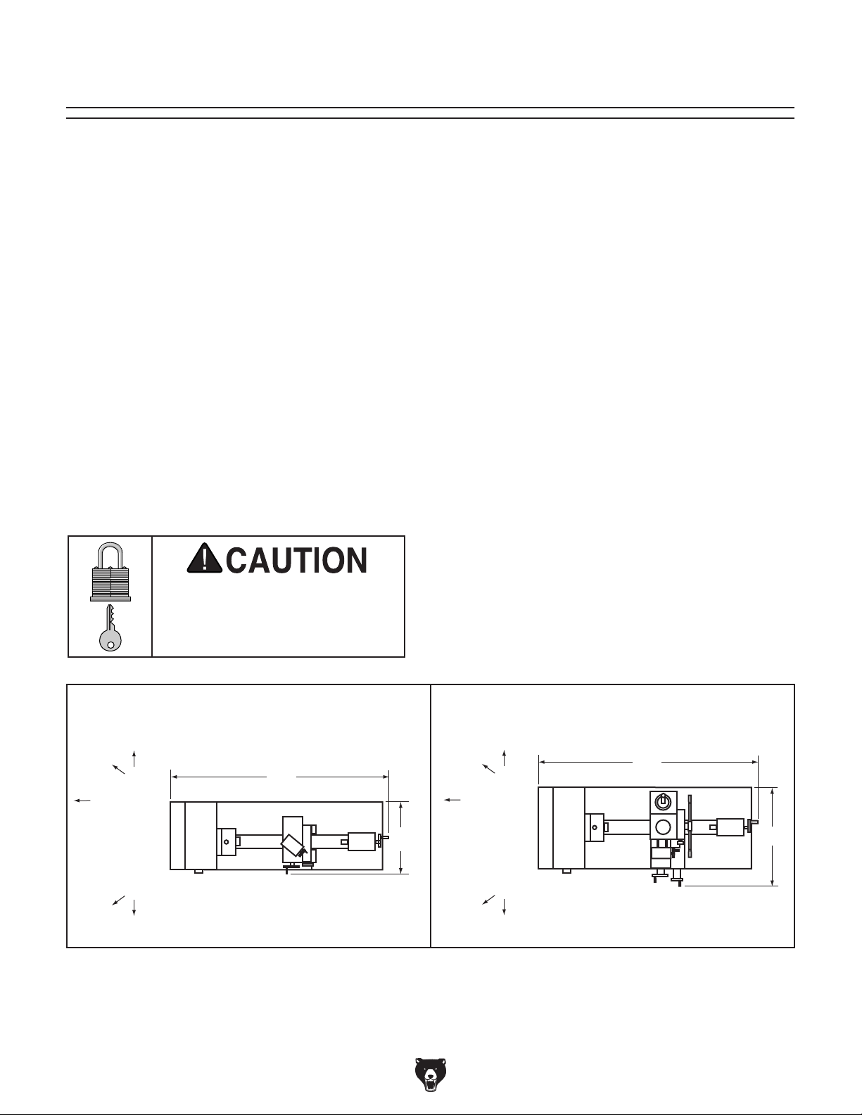
Site Considerations
Weight Load
Refer to the
of your machine. Make sure that the surface upon
which the machine is placed will bear the weight
of the machine, additional equipment that may be
installed on the machine, and the heaviest workpiece that will be used. Additionally, consider the
weight of the operator and any dynamic loading
that may occur when operating the machine.
Space Allocation
Consider the largest size of workpiece that will
be processed through this machine and provide
enough space around the machine for adequate
operator material handling or the installation of
auxiliary equipment. With permanent installations,
leave enough space around the machine to open
or remove doors/covers as required by the maintenance and service described in this manual.
See below for required space allocation.
Physical Environment
Extreme conditions for this type of machinery are
Place this machine near an existing power source.
other hazards. Make sure to leave enough space
Shadows, glare, or strobe effects that may distract
or impede the operator must be eliminated.
Machine Data Sheet for the weight
Keep
Workpiece
Loading
Area
Unobstructed
Children or untrained people
may be seriously injured by
this machine. Only install in an
access restricted location.
Model G0768 Model G0769
36"
Figure 13. Minimum working clearances.
The physical environment where the machine is
operated is important for safe operation and longevity of machine components. For best results,
operate this machine in a dry environment that is
free from excessive moisture, hazardous chemicals, airborne abrasives, or extreme conditions.
generally those where the ambient temperature
range exceeds 41°–104°F; the relative humidity
range exceeds 20%–95% (non-condensing); or
the environment is subject to vibration, shocks,
or bumps.
Electrical Installation
Make sure all power cords are protected from
traffic, material handling, moisture, chemicals, or
around machine to disconnect power supply or
apply a lockout/tagout device, if required.
Lighting
16"
Lighting around the machine must be adequate
enough that operations can be performed safely.
36"
Keep
Workpiece
Loading
Area
Unobstructed
20"
Model G0768/G0769 (Mfd. Since 6/17)
-23-
Page 30

Lifting & Placing
get help from other people
HEAVY LIFT!
Straining or crushing injury
may occur from improperly
lifting machine or some of
its parts. To reduce this risk,
and use a forklift (or other
lifting equipment) rated for
weight of this machine.
Do not attempt to lift or move the machine without using the proper lifting equipment (such as
a forklift or crane) or the necessary assistance
from other people. Refer to Needed for Setup on
Page 20 for details.
4. To balance load for lifting, move tailstock and
carriage to extreme right end of bedway, then
lock them in place.
Note: Before trying to move carriage, make
sure carriage lock is loose and half nut is
disengaged.
5. Wrap lifting slings around bed and between
leadscrew and bedway, as shown in Figure
14, to help prevent bending leadscrew during
lifting.
Lifting
Sling
To lift and place machine:
1. Remove shipping crate top and sides, then
remove chip pan, 4-jaw chuck, faceplate, and
toolbox from shipping pallet.
2. Position chip pan on selected mounting surface and use it as a template to mark hole
locations for mounting hardware (refer to
Leveling & Mounting on Page 25).
— If mounting machine to optional T26599
stand (see Accessories on Page 68),
align holes in chip pan with pre-drilled
mounting holes in stand.
3. Unbolt machine from shipping pallet.
Only use lifting slings and power lifting
equipment rated for at least 300 lbs. and in
good working condition. If machine falls or
tips over while moving it, serious personal
injury and property damage could result.
Figure 14. Example of lifting sling positions.
6. Attach lifting slings to forklift forks (or other
power lifting equipment).
Note: To balance the load when lifting, the
lifting strap closest to the headstock must be
slightly shorter than the lifting strap on the
tailstock side. If you are using lifting straps of
equal length, this can be achieved by wrapping the lifting strap on the headstock side
one or more times around the forklift fork, or
by placing a block of wood on the fork to raise
up the ends of the lifting strap.
7. Have an assistant hold mill headstock to
steady load, then lift machine just enough to
clear any obstacles and move it to its mounting position.
8. Properly mount machine as instructed in
Mounting subsection on Page 25.
-24-
Model G0768/G0769 (Mfd. Since 6/17)
Page 31

Mounting
Follow these guidelines when mounting your
machine to ensure safe and accurate cutting
results:
Number of Mounting Holes ............................ 2
5
Diameter of Mounting Hardware ................
⁄16"
The chip pan and lathe base have holes that allow
the machine to be mounted to the optional Model
T26599 Stand (see Figure 15) or a workbench.
Figure 15. T26599 Stand for G0768/G0769.
The T26599 Stand is specifically designed for
the G0768/G0769 and comes with pre-drilled
mounting holes that match the base of these
machines. You MUST mount your machine
to a stand or workbench to prevent it from
unexpectedly moving during operation, which
could lead to personal injury or property damage.
• Make sure stand or workbench can adequately support weight of machine and materials, and that it will not move or vibrate during operation.
• Use a silicon sealant between the machine
base and chip pan to prevent coolant or other
fluids from leaking through onto the stand,
workbench, or floor.
—If mounting machine to a stand, follow the
instructions included with it. Ensure stand
is anchored to floor.
— If mounting machine to a workbench, drill
holes all the way through workbench, and
use hex bolts, washers, and hex nuts to
secure machine in place (see example
below).
Hex Nut
Lock Washer
Flat Washer
Lathe
Silicon
Chip Pan
Workbench
Flat Washer
Model G0768/G0769 (Mfd. Since 6/17)
Hex Bolt
Figure 16. Example of a "Through Mount" setup.
-25-
Page 32

Leveling
For accurate turning results and to prevent
warping the cast iron bed and ways, the
lathe bedways MUST be leveled from sideto-side and from front-to-back on both ends.
Recheck the bedways 24 hours after
installation, two weeks after that, and then
annually to make sure they remain level.
Leveling machinery helps precision components,
such as bedways, remain straight and flat during the lifespan of the machine. The bed on a
lathe that is not level may slowly twist due to the
dynamic loads placed on the machine during
operation.
Assembly
With the exception of the handwheel handles, the
lathe is shipped fully assembled.
Use a flat head screwdriver to attach the handwheel
handles shown in Figure 18.
Cross Slide
Handle
Carriage
Handle
For best results, use a precision level that is at
least 12" long and sensitive enough to show a
distinct movement when a 0.003" shim (approximately the thickness of one sheet of standard
newspaper) is placed under one end of the level.
See Figure 17 for an example of a high-precision
level.
Figure 17. Grizzly Model H2683 12" Master
Machinist's Level.
Figure 18. Handwheel handles installed.
-26-
Model G0768/G0769 (Mfd. Since 6/17)
Page 33

Test Run
Once assembly is complete, test run the machine
to ensure it is properly connected to power and
safety components are functioning correctly.
If you find an unusual problem during the test run,
immediately stop the machine, disconnect it from
power, and fix the problem BEFORE operating the
machine again. The
table in the
SERVICE section of this manual can help.
setup instructions have been performed.
Operating an improperly set up machine
Serious injury or death can result from
Troubleshooting
using this machine BEFORE understanding
its controls and related safety information.
DO NOT operate, or allow others to operate,
machine until the information is understood.
3. Set spindle direction switch to neutral ("0"
position), and rotate spindle speed dial all the
way counterclockwise.
G0769 Only: Set lathe/mill selector switch to
"0" (see Figure 19 on Page on this page).
4. Shift feed direction dial to neutral (see Figure
20).
Feed
Direction
Lever
Feed Direction Dial
DO NOT start machine until all preceding
may result in malfunction or unexpected results that can lead to serious injury,
death, or machine/property damage.
To test run machine:
1. Make sure all tools and objects used during
setup are cleared away from machine.
2. Press Emergency Stop button cover (see
Figure 19) to prevent unexpected start up.
Spindle Direction
Switch Set to "O"
Lathe/Mill
Selector Switch
Emergency
Stop Button
LEFT
(Clockwise Rotation)
Figure 20. Neutral feed direction dial setting.
5. Make sure chuck and jaws, if installed, are
secure (see Chuck Installation on Page 32).
Note: If a chuck is not installed on the lathe,
you do not need to install one for this test run.
6. Disengage half nut with lever shown in
Figure 21.
CENTER
(Neutral)
Half Nut
Lever
Disengaged
RIGHT
(CCW Rotation)
Figure 19. Headstock controls (G0769 shown).
Model G0768/G0769 (Mfd. Since 6/17)
Spindle Speed
Dial
Half Nut
Lever
Engaged
Figure 21. Half nut lever disengaged.
-27-
Page 34

7. Connect machine to power. The spindle
speed RPM display will illuminate.
13. Rotate spindle speed dial all the way counterclockwise.
8. Press tab in on side of Emergency Stop button and lift switch cover to reset it.
9. Turn spindle direction switch to "F" position.
G0769 Only: Set lathe/mill selector switch to
"1" for lathe mode.
10. Press green ON button, leaving switch cover
open.
11. Slowly rotate spindle speed dial clockwise
until spindle speed display shows 100 RPM.
The spindle should rotate counterclockwise—
down and toward front of lathe.
The machine should run smoothly with little to
no vibration or rubbing noises.
— Strange or unusual noises should be
investigated and corrected before operating machine further. Always disconnect
machine from power when investigating or
correcting potential problems.
14. Set lathe/mill selector switch to "2" for mill
mode.
15. Rotate high/low gearbox knob to low "L" (see
Figure 22).
Note: It may be necessary to rotate spindle
by hand so gears will mesh.
Gearbox
Knob
Gearbox Knob
12. Press Emergency Stop button to turn lathe
OFF. Then, without resetting Emergency
Stop button, try to restart spindle rotation by
rotating spindle speed dial all the way counterclockwise and then clockwise. The spindle
should not start.
—If the spindle does start with Emergency
Stop button pressed in, the button is not
operating correctly. This safety feature
must operate properly before continuing
operation. Turn spindle speed dial all the
way counterclockwise to stop lathe, disconnect it from power, and call Tech Support
for help.
Model G0768: Congratulations! Test Run is
complete! Now perform the Spindle Break-
In procedure beginning on Page 29.
Model G0769: Continue with remaining test
run instructions.
L
(Low)
Figure 22. High/low gearbox knob set to low "L".
16. Reset Emergency Stop button.
17. Press green ON button.
18. Rotate spindle speed dial clockwise until
spindle speed display shows 50 RPM.
19. Mill spindle should begin clockwise rotation
(as viewed from top).
20. Press Emergency Stop button.
Congratulations! Model G0769 test run is
complete. Now perform the Spindle Break-
In procedure.
CENTER
(Neutral)
H
(High)
-28-
Model G0768/G0769 (Mfd. Since 6/17)
Page 35

Spindle Break-In
The spindle break-in procedure distributes lubrication
reduce the risk
of early
if there are any "dry" spots
or areas where lubrication has settled in the bearings. You
efore
placing
for the
first time when the machine is new or if it has
been sitting idle for longer than 6 months.
Always start the spindle break-in at the lowest
speed to minimize wear if there
Allow the spindle to run long enough to warm up
and distribute the bearing grease, then incrementally increase spindle speeds and repeat this process at each speed until reaching the maximum
spindle speed. Following the break-in procedure
in this progressive manner helps minimize any
potential wear that could occur before lubrication
is fully distributed.
tain the warranty. Failure to do this could
6. Rotate spindle speed dial all the way coun-
terclockwise, then press Emergency Stop
button.
throughout the bearings to
bearing failure
must complete this procedure b
operational loads on the spindle
are dry spots.
You must complete this procedure to main-
7. Set spindle direction switch to "R", then reset
Emergency Stop button.
8. Press ON button.
9. Rotate spindle speed dial to 2000 RPM and
run lathe for 10 minutes.
10. Rotate spindle speed dial all the way counterclockwise, then press Emergency Stop
button.
Congratulations! Lathe spindle break-in is complete.
Mill Spindle Break-In (G0769 Only)
1. Successfully complete Lathe Spindle Break-
In.
2. Set spindle direction switch to "F".
3. Set lathe/mill selector switch to "2" for mill
mode.
cause rapid wear-and-tear of spindle bearings once they are placed under load.
Lathe Spindle Break-In
1. Successfully complete Test Run procedure
beginning on Page 27.
2. Reset Emergency Stop button.
G0769 Only: Set lathe/mill selector switch to
"1" for lathe mode.
3. Press green ON button.
4. Rotate spindle speed dial until spindle speed
display shows 50 RPM and run lathe for minimum of 10 minutes.
5. Without stopping lathe, use spindle speed
dial to run lathe at 1000 and 2000 RPM for
10 minutes each.
Note: If necessary, refer to Setting Spindle
Speed on Page 47 for detailed instructions.
Model G0768/G0769 (Mfd. Since 6/17)
4. Rotate high/low gearbox knob to low "L."
5. Reset Emergency Stop button.
6. Press ON button.
7. Rotate spindle speed dial clockwise to 50
RPM and run spindle for a minimum of 10
minutes.
8. Rotate spindle speed dial all the way counterclockwise.
9. Press Emergency Stop button.
10. Rotate high/low gearbox knob to high "H".
11. Reset Emergency Stop button.
12. Press ON button.
13. Use spindle speed dial to run mill at 1000 and
2000 RPM for 10 minutes each.
-29-
Page 36

14. Rotate spindle speed dial all the way counterclockwise, then press Emergency Stop
button.
15. Repeat Steps 7–10 from Lathe Spindle
Break-In in a similar manner for mill.
Congratulations! Mill spindle break-in is complete.
Recommended
Adjustments
The following adjustments have been made at the
factory. However, because of the many variables
involved with shipping, we recommend you verify
these adjustments to ensure the best results:
Factory adjustments that should be verified:
• Tailstock alignment ........................ Page 39
• Cross slide backlash adjustment .....Page 82
• Leadscrew backlash ........................Page 82
• Gib adjustments ............................. Page 83
-30-
Model G0768/G0769 (Mfd. Since 6/17)
Page 37

SECTION 4: LATHE OPERATIONS
The purpose of this overview is to provide the novice machine operator with a basic understanding
of how the machine is used during operation, so
the
discussed later
in this manual
Due to the generic nature of this overview, it is
not intended to be an instructional guide. To learn
more about specific operations, read this entire
manual,
training from experienced
machine operators
outside of this manual by reading "how-to" books,
trade magazines, or websites.
To reduce your risk of
serious injury, read this
entire manual BEFORE
To complete a typical lathe operation, the
Operation Overview
machine controls/components
are easier to understand.
operator does the following:
1. Securely mounts workpiece in lathe.
2. Puts on safety glasses and a face shield, rolls
up sleeves, removes jewelry, and secures
any clothing, jewelry, or hair that could get
entangled in moving parts.
3. Installs tooling on toolpost, then backs it
away to establish a safe startup clearance.
seek additional
, and do additional research
using machine.
To reduce risk of eye or face injury from
flying chips, always wear approved safety
glasses and face shield when operating this
machine.
4. Removes all setup tools from lathe.
5. Checks for safe clearances by rotating
workpiece by hand at least one full revolution.
6. Moves slides to where they will be used during operation.
7. If using power feed, selects appropriate feed
rate and direction.
8. Resets Emergency Stop button and turns
spindle direction switch to "F".
9. Presses ON button and rotates spindle speed
dial to set correct spindle speed.
10. Uses carriage handwheels or power feed
options to move tooling into workpiece for
operations.
11. When finished turning, rotates spindle speed
dial completely counterclockwise, presses Emergency Stop button, then removes
workpiece.
If you are not experienced with this type
of machine, WE STRONGLY RECOMMEND
that you seek additional training outside of
this manual. Read books/magazines or get
formal training before beginning any projects. Regardless of the content in this section, Grizzly Industrial will not be held liable
for accidents caused by lack of training.
Model G0768/G0769 (Mfd. Since 6/17)
-31-
Page 38

Chuck & Faceplate
This lathe ships with the 3-jaw chuck installed.
This is a scroll-type chuck where all three jaws
move in unison when the chuck key is used.
This lathe ships with the 3-jaw chuck installed.
This is a scroll-type chuck where all three jaws
move in unison when the chuck key is used.
The included 4-jaw chuck features independent
jaws, which are used for square or unevenly-
shaped stock, and to mount work that needs to be
adjusted to near-zero total indicated runout.
The included faceplate has slots for T-bolts that
hold standard or custom clamping hardware. With
the correct clamping hardware, a faceplate offers
a wide range of uses, including machining nonconcentric workpieces, straight turning between
centers, off-center turning, and boring.
risk of workpiece or chuck being thrown
Mounting
This lathe is equipped with an intrinsic backplate
spindle nose. With this type of spindle, a chuck or
faceplate is mounted directly to the backplate with
hex nuts.
Chuck Installation
To ensure accurate work, it is extremely important
to make sure the spindle nose and chuck mating
surfaces are clean. Even a small amount of lint or
debris can affect accuracy.
The chuck is properly installed when it is seated
against the backplate shoulder (see Figure 24).
Never use spindle speeds faster than chuck
RPM rating or safe limits of your workpiece.
Excessive spindle speeds greatly increase
from machine with deadly force!
Installation &
Removal Device
Place a piece of plywood over the bedways to protect them from damage if a chuck or other tooling
is dropped (see below).
Mounting
Hole
Figure 24. Spindle backplate parts.
Tools Needed: Qty
Open-End Wrench 13mm .................................. 1
Lathe Chuck Key ............................................... 1
To install chuck:
1. DISCONNECT MACHINE FROM POWER!
2. Use an appropriate device to protect ways
(refer to Installation & Removal Device subsection).
3. Thoroughly clean and wipe down all mating
surfaces with a lightly-oiled, lint-free rag.
Shoulder
Inside
Taper
Plywood Protection
Plate for Chucks
Installed by Hand
Figure 23. Example of common device used
during chuck installation and removal.
-32-
Model G0768/G0769 (Mfd. Since 6/17)
Page 39

4. Insert (3) M8-1.25 X 35 set screws through
This 3-jaw, scroll-type chuck has an internal scrollgear
djusted
with the chuck key
cylindrical
parts on-center with the axis of spindle rotation
and can be
at high speeds if the workpiece
is properly clamped and balanced.
IMPORTANT: Never mix jaw types or
positions
to accommodate an odd-shaped workpiece.
T
may throw
the workpiece
chuck or a faceplate.
mounting holes in spindle backplate, as
shown in Figure 25. Make sure chuck seats
firmly and evenly against backplate shoulder.
Scroll Chuck
Clamping
Spindle
Backplate
Chuck Screw
Figure 25. Inserting chuck into backplate.
5. Use (1) 8mm flat washer and (1) M8-1.25 hex
nut on each chuck screw to secure chuck
(see Figure 26). Tighten hex nuts evenly a
small amount at a time and in multiple steps.
Hex Nut
that moves all jaws in unison when a
. This chuck holds
rotated
he chuck will spin out of balance and
! Instead, use an independent jaw
Safer Inside
Jaw Use
CORRECT
Safer Outside
Jaw Use
Bar Stock
Unsafe Jaw Position and
Poor Scroll Gear Engagement
Insufficient
Jaw Clamping
INCORRECT
Unstable
Workpiece
Poor Grip
Flat Washer
Figure 26. Chuck secured against backplate.
Model G0768/G0769 (Mfd. Since 6/17)
CORRECT
Safer Outside
Jaw Use
CORRECT
Safer Inside
Jaw Use
CORRECT
Shallow
Bar Stock
Unsafe Inside
Shallow
Bar Stock
Unsafe Jaw
Position
Unsafe Jaw Position
Cylinder
Poor Scroll
Gear Engagement
Unstable
Workpiece
INCORRECT
Jaw Use
Poor Scroll
Gear
Engagement
INCORRECT
INCORRECT
Figure 27. Jaw selection and workpiece holding.
-33-
Page 40

Changing Jaw Set
The 3-jaw scroll chuck included with the lathe
features inside and outside
sets
move in unison to
center a concentric workpiece.
When installing the jaws
sure they are installed correctly. Incorrect installation will result in jaws that do not converge evenly
and are unable to securely clamp a workpiece.
Jaws are numbered from 1–3 (see Figure below).
The number is typically stamped on the side or
bottom. Jaws are designed to be installed counterclockwise in numerical order in the matching
numbered jaw guides, so they will hold a concentric workpiece evenly.
To change jaw set:
1.
2.
(refer
subsec-
3.
4.
5.
n safe place free
6.
of outer scroll-gear lead thread about to enter
a jaw guide (see below).
3
7. Insert jaw #1 into jaw guide #1 and hold jaw
8
engage tip of scroll-gear lead thread into jaw.
9
converge
sequentially
tion.
DISCONNECT MACHINE FROM POWER!
hardened steel jaw
(see Figure below), which
, it is important to make
Inside SetOutside Set
Figure 28. Chuck and jaw selection.
Use appropriate device to protect ways
to Installation & Removal Device
tion).
Insert chuck key and turn it counterclockwise
to back jaws out and remove them individually in descending order (i.e., 3, 2, 1).
Use mineral spirits to clean debris and grime
from jaws and chuck jaw guides.
Apply thin coat of NLGI #2 grease to surfaces
of removed jaw set. Store i
from moisture and abrasives.
Rotate chuck key clockwise until you see tip
2
1
1
Jaw Guides
Jaw Numbers
1
1
2
3
Figure 29. Jaw guide and jaw numbers.
3
-34-
Lead Thread
Figure 30. Lead thread on scroll gear.
against scroll-gear.
. Rotate chuck key clockwise one turn to
Pull jaw; it should be locked into jaw guide.
2
. Install remaining jaws in numerical order, in
the same manner. The jaws should
evenly at center of chuck.
— If jaws do not converge evenly, remove
them. Check that jaw numbers and jaw
guides match. Re-install jaws
1–3, making sure each one engages with
scroll-gear lead thread during its first rota-
Model G0768/G0769 (Mfd. Since 6/17)
Page 41

4-Jaw Chuck
Refer to the Chuck Installation subsection for
instructions on installing the 4-jaw chuck.
The 4-jaw chuck features independently adjustable jaws for holding non-concentric or off-center
workpieces. Each jaw can be independently
removed from the chuck body and reversed for a
wide range of work holding versatility.
Because of dynamic forces involved in
Mounting Workpiece
1.
2.
Chuck Safety & Support Devices
3.
4.
device, position workpiece so it is centered in
chuck.
5. Tighten each jaw in small increments. After
similar to sequential order shown below.
6. After workpiece is secured by jaws, use dial
indicator to make sure workpiece is centered
make fine adjustments by slightly loosening
below for an example).
tightening first jaw, continue tightening
remaining jaws in an opposing sequence,
machining a non-concentric or off-center
workpiece, always use a low spindle speed
to reduce risk of workpiece coming loose
and being thrown from lathe, which could
cause death or serious personal injury.
DISCONNECT MACHINE FROM POWER!
Use an appropriate device to protect ways
(refer to
section for more details).
1
4
Figure 31. 4-jaw chuck tightening sequence.
in chuck.
— If workpiece is not correctly centered,
one jaw and tightening opposing jaw until
workpiece is correctly positioned (see
3
Workpiece
Center Point
2
Use chuck key to open each jaw so workpiece will fit into spindle opening and lay flat
against chuck face and jaw steps.
With help from another person or a holding
Model G0768/G0769 (Mfd. Since 6/17)
Figure 32. Example of a non-cylindrical
workpiece correctly positioned on a 4-jaw chuck.
-35-
Page 42

To mount a non-concentric workpiece to a
faceplate:
1.
2.
across bed ways
3.
piece when clamping it to faceplate. If neces-
operation.
Faceplate
Failure to properly secure workpiece to
faceplate could cause workpiece to be
thrown from lathe with deadly force. To
independent clamping devices to hold
Machining non-concentric workpieces at
thrown from lathe with deadly force. To
RPM, and use
counter-weights to balance faceplate or
Refer to the prior Chuck Installation subsection
for instructions on installing the faceplate.
The faceplate included with your lathe can be
used for a wide range of operations, including
machining non-concentric workpieces, straight
turning between centers, off-center turning, and
boring.
The tools needed for mounting a workpiece will
vary depending on the type of setup you have.
high speeds could cause workpiece to be
reduce this risk, use a low
DISCONNECT MACHINE FROM POWER!
Position appropriate device
to protect them from any potential damage
from workpiece contact during installation.
With help from another person or holding
device to support workpiece, position it onto
faceplate and clamp it in place with a minimum of three independent clamping devices
(see below for an example).
Be sure to take into account rotational and
cutting forces that will be applied to work-
sary, use counter-weights to balance assembly and use a dial indicator to make sure
workpiece is properly positioned for your
workpiece.
reduce this risk, use a minimum of THREE
workpiece onto faceplate.
Non-Cylindrical
Workpiece
Clamp
Faceplate
Figure 33. Example of a workpiece clamped in a
faceplate.
-36-
Model G0768/G0769 (Mfd. Since 6/17)
Page 43

Tailstock
The tailstock is typically used to support long
workpieces at the side opposite the spindle, using
a live or dead center. It can also hold a tapered
drill bit (or a drill chuck with a regular drill bit) for
boring holes. Unlike boring done with a drill press
where the workpiece is fixed and the drill bit
rotates, the drill bit in a tailstock remains stationary while the workpiece is rotated by the spindle.
The entire tailstock can be repositioned and
locked in place along the length of the bed. An
independently controlled offset adjustment allows
the upper part of the tailstock to move perpendicular to the bedways so it can be aligned with
the spindle center (for concentric turning) or offset
from the spindle center (for tapered turning).
The tailstock quill also features independent
adjustment controls that allow it to be advanced
toward the spindle or locked firmly in position.
1. Rotate tailstock lock lever clockwise (facing
2.
3.
to lock tailstock against bedways.
1. Rotate quill lock lever counterclockwise to
2.
toward spindle or counterclockwise to move it
3.
quill.
Tailstock Quill Specs
Graduated Dial on Handwheel
Increments ................................................. 0.001"
One Full Revolution ..................................... 0.04"
Quill Lock
Lever
Tailstock Lock
Lever
Increments on Quill Scale
Inch ................................ 0"–2" in
Metric .................... 0–50mm in 1mm Increments
1
⁄8" Increments
Positioning Tailstock
machine) to unlock tailstock from bedways.
Slide tailstock to desired position by pushing
it along the bedways.
Rotate tailstock lock lever counterclockwise
Using Quill
loosen quill.
Turn quill handwheel clockwise to move quill
away from spindle.
Rotate quill lock lever clockwise to secure
Quill
Offset Adjustment
Figure 34. Tailstock controls and features.
Model G0768/G0769 (Mfd. Since 6/17)
Screw (1 of 2)
Quill
Handwheel
-37-
Page 44

To install tooling in tailstock:
1.
2.
3.
attempting to twist it—a firmly seated tool will
4.
is close to, but not touching, workpiece, then
5.
tool into workpiece.
Installing Tooling
Note: If the tooling has an open hole in the end,
then a screw can be threaded into the end of the
tool to provide a solid surface for the quill pin to
push against when the quill is retracted for tool
removal. Otherwise, removal of such tooling may
be difficult.
The tailstock quill can be offset from the spindle
centerline for turning tapers. Offsetting the quill
toward the front of the lathe results in a taper at
the tailstock end. Conversely, offsetting the quill
toward the back of the lathe results in a taper at
the spindle end.
1. Use shop rag to hold tool.
2.
forced out of quill.
Note: The marks on the offset indicator are arbitrary. For a precise offset, use a dial indicator to
check quill movement while adjusting the screws.
The tailstock quill accepts MT#2 tapered arbors
(see the Figures below for examples).
With tailstock locked in place, unlock quill,
then use handwheel to extend it approximately 1".
Tang
Solid
End
Figure 35. Types of tapered arbors and tooling.
Open
End
Solid
End
Screw
End
Tang
Thoroughly clean and dry tapered mating
surfaces of quill and center, making sure no
lint or oil remains on tapers.
With a firm and quick motion, insert tool into
quill. Check to see if it is firmly seated by
not twist.
Unlock tailstock and move it until tip of tool
lock tailstock.
Start spindle rotation, unlock quill lock lever,
then turn quill handwheel clockwise to feed
Removing Tooling
Rotate quill handwheel counterclockwise to
fully retract quill into tailstock until tool is
Figure 36. Example photos of inserting tools into
the tailstock.
-38-
Offsetting Tailstock
Adjustment
Set Screw (1 of 2)
Offset
Indicator
Figure 37. Left offset adjustment.
Model G0768/G0769 (Mfd. Since 6/17)
Page 45

Tools Needed Qty
This is an essential adjustment that should be verified or performed each time the tailstock is used
to turn concentric workpieces between centers
or immediately after offsetting the tailstock when
turning a taper. If the tailstock is not aligned with
the spindle centerline when it is supposed to be,
turning results will be inaccurate along the length
of the workpiece.
Hex Wrench 4mm .............................................. 1
To offset tailstock:
1. Loosen tailstock lock to release clamping
pressure on top and bottom castings.
2. Rotate adjustment set screws in opposite
directions for desired offset (see below).
Aligning Tailstock to Spindle Centerline
Items Needed Qty
Hex Wrench 4mm .............................................. 1
Round Stock 2" x 6" .......................................... 2
To align tailstock to spindle centerline:
Turn
CCW
Figure 38. Example of set screw adjustment in
relation to tailstock movement.
3. Tighten tailstock lock to secure the offset.
Turn
CW
Turn
CW
Turn
CCW
1. Center drill both ends of one piece of round
stock, then set it aside for use in Step 5.
2. Use another piece of round stock to make
a dead center, and turn it to a 60° point, as
illustrated below.
Figure 39. Turning a dead center.
Note: As long as this dead center remains in the
chuck, the point of the center will remain true to
the spindle centerline. The point will have to be
refinished whenever the center is removed and
then returned to the chuck.
Model G0768/G0769 (Mfd. Since 6/17)
-39-
Page 46

— If test stock is thinner at tailstock end,
the
distance of taper amount, as shown below.
3. Install center in tailstock.
4. Attach a lathe dog to the test stock from Step
1, then mount it between centers, as shown
below.
7. Use calipers to measure both ends of the
workpiece.
— If test stock is thicker at tailstock end,
1
move tailstock toward front of lathe
⁄2 the
distance of the amount of taper, as shown
below.
Figure 40. Example of stock mounted between
the centers.
5. Turn 0.010" off stock diameter.
6. Mount a test or dial indicator so plunger is on
tailstock quill.
Move tailstock toward
1
front of lathe
/2 the
amount of taper.
Looking down from above.
Figure 41. Adjust tailstock toward the operator.
move tailstock toward back of lathe 1⁄2
Looking down from above.
-40-
Move tailstock toward
back of lathe
1
/2 the
amount of taper.
Figure 42. Adjust tailstock away from operator.
8. Repeat Steps 5–7 until desired accuracy is
achieved.
Model G0768/G0769 (Mfd. Since 6/17)
Page 47
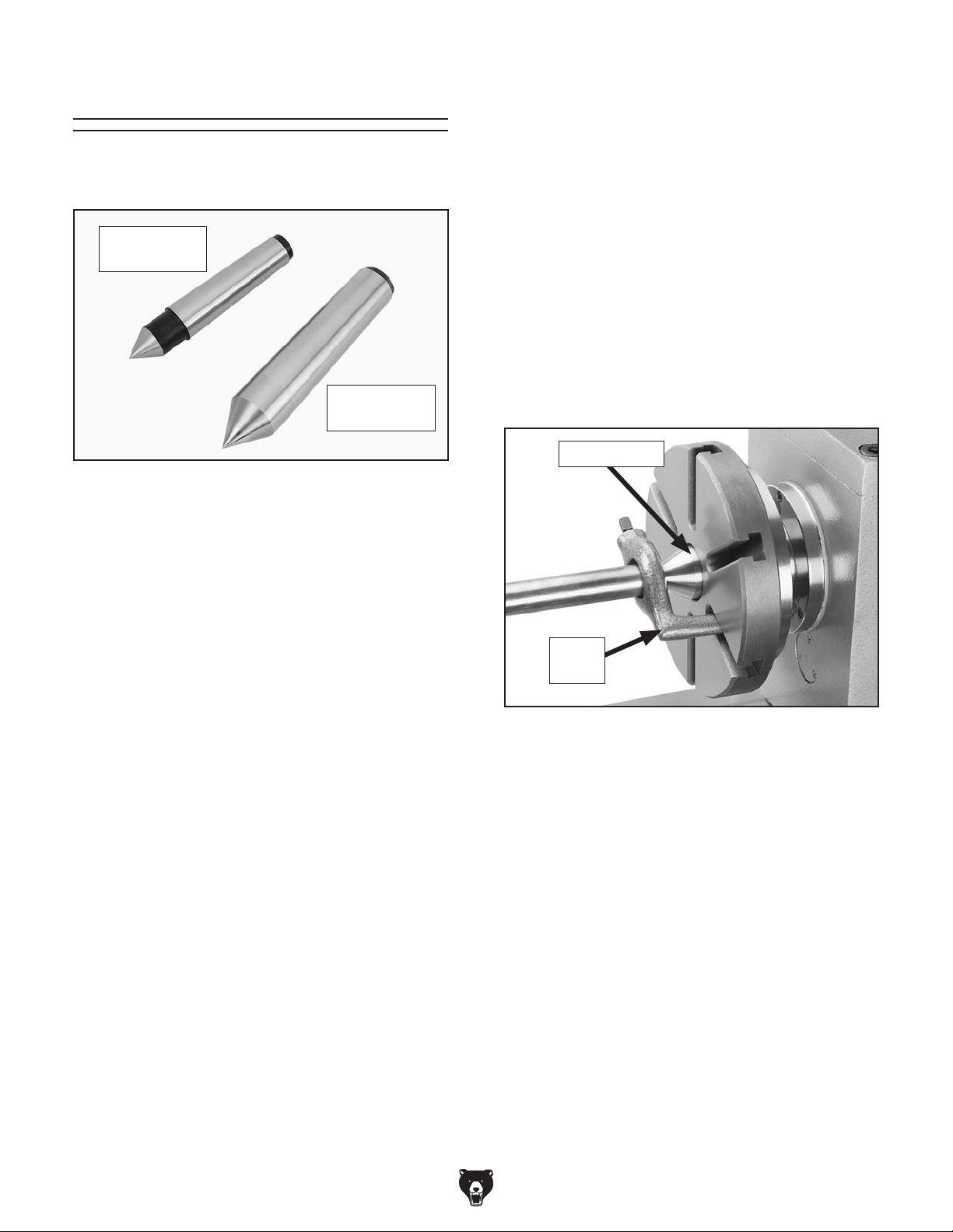
Centers
Mounting Dead Center in Spindle
1. DISCONNECT MACHINE FROM POWER!
Figure 43 shows the MT#2 and MT#3 dead cen-
ters included with the lathe.
MT#2 Dead
Center
MT#3 Dead
Center
Figure 43. Dead centers.
Dead Centers
Dead centers are one-piece, high-speed steel
centers that require low spindle speeds and a
small amount of oil to reduce friction heat that may
damage the workpiece.
Mount the MT#2 dead center (see Figure 43)
in the tailstock. Since the workpiece will rotate
against the center and generate friction, the tip of
the center must be lubricated to avoid premature
wear and maximize smooth operation.
Mount the MT#3 dead center (see Figure 43) in
the spindle for operations where the workpiece
rotates with the center and does not generate
friction.
2. Thoroughly clean and dry all mating surfaces
of spindle bore and center, making sure that
no lint or oil remains on these surfaces.
3. Mount chuck or faceplate onto spindle, whichever is correct for your operation.
4. Insert MT#3 center into spindle bore through
chuck or faceplate.
Below is an example photo of a dead center
installed in spindle, using a lathe dog and
faceplate for turning between centers.
Dead Center
Lathe
Dog
Figure 44. Example of using a dead center with
a faceplate and lathe dog.
Removing Center from Spindle
To remove the center from the spindle, insert a
piece of round bar stock (or similar tool) through
the outside end of the spindle. Hold onto the center with a gloved hand or shop rag, then tap the
bar stock to knock the center loose.
Model G0768/G0769 (Mfd. Since 6/17)
-41-
Page 48

Mounting Center in Tailstock
To mount a center in tailstock:
1.
2.
making sure no lint or oil remains on tapers.
3. Use quill handwheel to feed quill out from
casting approximately 1".
4. Insert center into tailstock quill.
5.
Note: Only apply enough pressure with
tailstock quill to securely mount workpiece
ter against workpiece, or it may become
difficult to remove later, and it will result in
age workpiece and center.
To remove the center from the quill, hold onto it
with a gloved hand or shop rag, then rotate the
quill handwheel counterclockwise to draw the quill
back into the casting until the center releases.
To avoid premature wear of dead center
1. DISCONNECT MACHINE FROM POWER!
2. Drill center holes in both ends of workpiece.
3. Install dead center in spindle with lathe dog
and chuck, faceplate or drive plate, then
install live center or carbide-tipped dead cen-
ter in tailstock.
4. Lubricate dead center point and workpiece
center holes, then mount workpiece between
centers and hold it in place with light pressure
from tailstock center.
5. Seat center firmly into quill by rotating quill
against workpiece (see example below).
Note: Only apply enough pressure to securely
mount the workpiece between centers. Avoid
over-tightening the center against the workpiece,
or it may become difficult to remove later. Also,
over-tightening will result in excessive friction and
heat, which may damage the workpiece or center.
The included #2 dead center or a live center (not
included) can be used in the tailstock. Mounting
instructions are the same for both. The Figure
below shows an example photo of a dead center
mounted in a tailstock.
Dead Center
Figure 45. Example of using dead center
installed in the tailstock.
Removing Center from Tailstock
Mounting Workpiece Between Centers
1. DISCONNECT MACHINE FROM POWER!
2. Drill center holes in both ends of workpiece.
3. Install MT#3 dead center in spindle with lathe
dog and chuck or faceplate, then install live
center or MT#2 dead center in tailstock.
4. Lubricate MT#2 dead center point and
workpiece center holes, then mount workpiece
between centers and hold it in place with light
pressure from tailstock center.
DISCONNECT MACHINE FROM POWER!
Thoroughly clean and dry tapered mating
surfaces of tailstock quill bore and center,
Note: The maximum quill travel is 2", but
we do not recommend extending the quill
more than 1" or stability and accuracy will be
reduced.
Seat center firmly into quill during workpiece
installation by rotating quill handwheel clockwise to apply pressure with center engaged
in center hole of workpiece.
between centers. Avoid overtightening cen-
or damage to workpiece, use low spindle
speeds and keep tip of dead center mounted
in tailstock well lubricated.
handwheel clockwise to apply pressure
Figure 46. Example photo of a workpiece
mounted between two centers.
excessive friction and heat, which may dam-
-42-
Model G0768/G0769 (Mfd. Since 6/17)
Page 49

Steady Rest
The follow rest mounts to the saddle and supports
the workpiece near the cutting tool to prevent
deflection
The
as the fingers on the steady rest.
Tip: To reduce the effects of friction, lubricate the
finger tips with generous amounts of anti-sieze
lubricant during operation.
The steady rest supports long shafts and can
be
bedway
components shown below
the controls before using it.
mounted anywhere along the length of the
. Familiarize yourself with the steady rest
to better understand
Tools Needed for Installation/Removal Qty
Open-End Wrench 13 mm .................................. 1
Open-End Wrench 14 m m .................................. 1
Finger
Finger
Adjustment
Finger
Lock Nut
Lock
Nut
Adjustment
Knob
Knob
Finger
7. Lubricate finger tips with an anti-seize lubri-
cant during operation. Note: Mill or file the
tips if they show wear.
Follow Rest
from the pressure of the cutting tool.
follow rest fingers adjust in the same manner
Tool Needed Qty
Hex Wrench 4mm .............................................. 1
Clamp
Plate
Figure 47. Steady rest components.
To install and use steady rest:
1. DISCONNECT MACHINE FROM POWER!
2. Thoroughly clean all mating surfaces.
3. Place steady rest base on bedways and
secure with clamp plate, hex bolt, and lock
nut.
4. Loosen finger lock nuts (see Figure 47), turn
finger adjustment knobs, and adjust fingers
as required for workpiece.
5. Loosen steady rest lock nut, position steady
rest where required to properly support
workpiece, then secure lock nut.
Cap
Screws
Figure 48. Follow rest attachment.
6. Turn finger adjustment knobs so fingers are
barely touching workpiece, then tighten finger
lock nuts.
Model G0768/G0769 (Mfd. Since 6/17)
-43-
Page 50

Compound Rest Four-Way Tool Post
The four-way tool post is mounted on top of the
compound rest
tools
Each tool can be quickly indexed to the workpiece
by
post to the desired position, then retightening the
handle to lock the tool into position.
To install tool in tool post:
1
underneath them (see below).
2. Firmly secure cutting tool with at least two
3.
terline, as instructed in next subsection.
The compound rest handwheel has an indirectread graduated scale. This means that the distance shown on the scale represents the actual
distance the cutting tool moves. The base of the
compound rest has another graduated scale used
for setting the cutting tool to a specific angle.
Graduated Dial
Increments ............................... 0.001" (0.025mm)
One Full Revolution ..................... 0.05" (1.27mm)
Tool Needed Qty
Hex Wrench 4mm .............................................. 1
To set compound rest angle:
to be loaded simultaneously.
loosening the top handle, rotating the tool
Installing Tool
Tool Needed Qty
Tool Post T-Wrench ........................................... 1
and allows a maximum of four
1. Loosen cap screws shown in Figure 49.
Cap
Screws
Figure 49. Compound rest angle adjustments.
2. Rotate rest to desired angle, as indicated by
scale at base, then retighten cap screws.
Tip: The first time you set the compound rest
angle for cutting threads, mark the location
on the cross slide as a quick reference point.
This will allow you to quickly return the compound rest to that exact angle the next time
you need to cut threads.
Angle
Scale
. Adjust tool post bolts so cutting tool can fit
Tool Post
Bolt
Cutting
Tool
Figure 50. Example of tool mounted in tool post.
Over-extending a cutting tool from the post
will increase risk of tool chatter, breakage,
or tool loosening during operation, which
could cause metal pieces to be thrown at
the operator or bystanders with great force.
DO NOT extend a cutting tool more than 2.5
times the width of its cross-section (e.g.,
2.5 x 0.5" = 1.25").
-44-
tool post bolts.
Check and adjust cutting tool to spindle cen-
Model G0768/G0769 (Mfd. Since 6/17)
Page 51

Aligning Cutting Tool with Spindle
For most operations, the cutting tool tip should be
aligned with the
centerline, as illustrated
below.
There are a number of ways to check and align
the cutting tool to the spindle centerline. If necessary, you can raise the cutting tool by placing
steel shims underneath it. The shims should be
as long and as wide as the cutting tool to properly
support it.
Below are two common methods:
• Move the tailstock center over the cross slide
to measure the distance
cutting tool height so
•
tailstock
Aligning Tailstock To Spindle Centerline
for detailed instructions).
To align cutting tool with tailstock center:
1.
2.
3.
4.
aligned vertically with center tip, as illustrated
below.
Centerline
spindle
Tools Needed Qty
Tool Post T-Wrench ........................................... 1
Steel Shims ....................................... As Needed
Cutting Tool ....................................................... 1
Tailstock Center ................................................. 1
Cutting
Tool
Figure 51. Cutting tool aligned with spindle
centerline (viewed from tailstock).
Spindle
Center
Line
Mount cutting tool in tool post, then secure
post so tool faces tailstock.
Install center in tailstock, and position center
tip near cutting tool tip.
Lock tailstock and quill in place.
Adjust height of cutting tool so tool tip is
(Top View)
Tailstock
Center
Cutting
Tool
and use a fine ruler
from the surface of the cross slide to the tip
of the center. Adjust the
it is the same distance above the cross slide
as the tailstock center.
Align the tip of the cutting tool with a
center, as instructed in the following procedure. For this to work, the tailstock must
be aligned to the spindle centerline (refer to
Model G0768/G0769 (Mfd. Since 6/17)
Cutting
Tool
Figure 52. Cutting tool aligned to the tailstock
center.
Tailstock
Center
(Side View)
-45-
Page 52

Manual Feed
Using the correct spindle speed is important for
getting
maximizing tool life.
To set the spindle speed for your operation, you
will need to: 1) Determine the
spindle speed
for the cutting task, and 2)
lathe
controls to produce the required spindle speed.
Many variables affect the optimum spindle speed
to use for any given operation
important are the recommended cutting speed for
the workpiece material and the diameter of the
workpiece, as noted in the formula shown below.
Cutting speed, typically defined in feet per minute
(FPM), is the speed at which the edge of a tool
moves across the material surface.
A recommended cutting speed is an ideal speed
for cutting a
the desired finish and optimize tool life.
The books
Machine
Shop Practice
vide excellent recommendations for which cutting
speeds to use when calculating the spindle speed.
The
also provide a wealth of additional
information about the variables that affect cutting
speed and
A
spindle speed calculators that can be found on
the internet.
take into
account the applicable variables in order to determine the best spindle speed for the operation.
The cutting tool can be manually fed into the
workpiece using the carriage, cross slide, and
compound rest handwheels shown below.
Spindle Speed
safe and satisfactory results, as well as
Carriage
Handwheel
Cross Slide
Handwheel
Figure 53. Manual feeding controls.
Compound
Rest
Handwheel
Carriage Handwheel
Graduated Dial
Increments ................................... 0.01" (0.25mm)
One Full Revolution .......................... 1" (25.4mm)
Use the carriage handwheel to move the carriage
left or right along the bed. Adjust the position of
the graduated scale by holding the handwheel
with one hand and turning the dial with the other.
best
Configure the
Determining Spindle Speed
, but the two most
*Recommended
Cutting Speed (FPM) x 12
Dia. of Cut (in inches) x 3.14
Spindle
Speed
=
(RPM)
*Double if using carbide cutting tool
Figure 54. Spindle speed formula for lathes.
Cross Slide Handwheel
Graduated Dial
Increments ................................. 0.002" (0.05mm)
One Full Revolution .....................0.08" (2.03mm)
Use this handwheel to move the tool toward and
away from the work. The cross slide handwheel
has a direct-read graduated dial, which shows the
total amount of material removed from the diameter of the workpiece.
Compound Rest Handwheel
Graduated Dial
Increments .............................. 0.001" (0.025mm)
One Full Revolution ..................... 0.05" (1.27mm)
Use this handwheel to move the cutting tool linearly along the set angle of the compound rest.
Set the compound rest angle by hand-rotating
it and securing it with the two cap screws (see
Figure 49 on Page 44). The compound rest has
an indirect-read graduated dial.
-46-
type of material in order to produce
Machinery’s Handbook or
, and some internet sites, pro-
se sources
they are a good educational resource.
lso, there are a large number of easy-to-use
These sources will help you
Model G0768/G0769 (Mfd. Since 6/17)
Page 53

Setting Spindle Speed Range
One of two spindle speed ranges is selected by
repositioning the top V-belt between the spindle
and idler pulleys (see Figure 55). Select the A
position for low (50-1000 RPM) or B position for
hig h (100 –2000 RPM) speed ranges. The V-belt
diagram below is also found on the headstock.
Configuration Example
Follow this example to gain a better understanding of how to set the lathe spindle speed.
To set spindle speed to 100 RPM:
1. DISCONNECT MACHINE FROM POWER!
Tools Needed Qty
Hex Wrench 4mm .............................................. 1
Spindle
Pulley
Top
V-Belt
Idler
Pulley
Motor
Pulley
Figure 55. Belt positioned for low speed.
Low
A
High
B
M
Setting Spindle Direction & Speed
Set the spindle rotation direction to forward or
reverse with the spindle direction switch, shown
in Figure 56. Reset the Emergency Stop button,
press the ON button, select "1" on the lathe/mill
selector (Model G0769 only) then turn the spindle
speed dial clockwise until the desired spindle
speed displays on the spindle speed RPM display.
2. Open end cover.
3. Loosen tensioner screw (see Figure 57) to
loosen V-belt tension.
Tensioner
Screw
Figure 57. Location of tensioner screw used for
tightening/loosening V-belts when changing belt
positions.
Lathe/Mill Selector
Spindle
Direction
Switch
Spindle
Speed Dial
Figure 56. Spindle speed and direction controls.
Model G0768/G0769 (Mfd. Since 6/17)
Switch (G0769 Only)
Emergency
Stop
Button
Spindle
Speed RPM
Display
-47-
Page 54

4. Move top V-belt to A position (see Figure 58)
to select low speed range (50–1000 RPM).
Understanding Gear
Charts
Low
A
Top
V-Belt
Figure 58. V-belt positioned in low speed range.
5. Re-tension V-belt (refer to "Tensioning
V-Belts" on Page 81).
6. Re-install end cover.
7. Reset Emergency Stop button.
8. Rotate spindle direction switch to "F" or "R",
and press ON button.
9. Rotate spindle speed dial clockwise until
spindle speed display reads 100 RPM.
High
B
M
This subsection explains how to understand the
feed and thread charts on the headstock. If you do
not understand lathe gear charts, or need a quick
refresher, read this before configuring the end
gears for power feeding or threading operations.
Feed & Thread Charts Label
The feed and thread charts label (see Figure 59)
provides information for setting up end gears for
threading or non-threading operations. The top
displays a feed chart, the bottom displays metric
and inch thread charts.
Feed & Thread
Charts Label
Feed Chart
Thread
Charts
Figure 59. Feed and thread charts label.
Feed Chart—Displays headstock end gear posi-
tions for different speeds of automatic feed (power
feed) used with turning operations (see Figure
60).
in/
40
A
B
A
CCD
EEF
0.0037"
84
20
80 80
Figure 60. Feed chart.
0.0068"
30 72
80
33 80
30
B
D
F
-48-
Model G0768/G0769 (Mfd. Since 6/17)
Page 55

Thread Charts—Display headstock end gear
0.0037"
84
20
A
A
40
in/
CCD
D
B
B
EEF
F
80 80
80
30 72
33 80
30
0.0068"
positions used for cutting various metric or inch
threads (see Figure 61).
How to Read the Feed Chart
Figure 62 identifies the three available feed rates
and the feed icon at the top of the feed rate chart.
A
B
C D
E F
A
B
C D
E F
A
B
C D
E F
A
B
C D
E F
mm
0.40
0.50 0.60 0.70 0.80 1.00
55
60 70
80
30 33 53 30 60 40 40 4030 3370
80
80
1.25 1.50 1.75 2.00 2.50 3.00
53
57
71 71 63
57 72 80
80 80
80 63 63
20
80
71 7163 33 30 60 40 40
n/1"
9 10 11 12 13 14 16
57 57 72 72
53
80 80
30
19 20 22 24 32 40 44
53 53 53 72 63 70
63
50 50 558080 80 80 80
Figure 61. Threading charts.
7272 80 70 40 40 40
30 33 40 65 70 80 60
80 606071 53 55 33 3055 5540 30
63 5755
Metric
Thread Chart
70
70
506084805060
Inch Thread
Chart
18
6060 60 63
Feed Rates
in/
Feed Rate
Icon
40
0.0037"
B
84
20
80 80
A
CCD
EEF
Figure 62. Chart displays the three feed rates.
Figure 63 identifies the end gears on the upper,
middle, and lower shafts, and the 40-tooth (40T)
spindle gear. The gears are represented by letters
in the columns and the diagram.
Upper
Shaft
Gears
Columns
0.0068"
30 72
80
33 80
30
B
D
F
Spindle
in/
40
0.0037"
0.0068"
A
Gear
A
Model G0768/G0769 (Mfd. Since 6/17)
30 72
A
CCD
EEF
Figure 63. Identification of upper, middle and
84
B
80
20
80 80
Lower Shaft Gears
Middle Shaft Gears
lower shaft gears.
30
33 80
B
D
F
-49-
Page 56

Each shaft has room to mount gears in two posi-
A
40
in/
A
40
in/
C
D
B
E
E
F
80 80
32 40 44
65 70 80 60
6060 60 63
13 14 16
18
80 80 80
33 3055 5540 30
72 63 70
72 72
40 40 40
63 57
tions—forward and rear (see Figure 64).
0.0037"
0.0068"
How to Read the Thread Charts
Figure 66 identifies the charts to use when set-
ting carriage feed movement for metric or inch
threading.
30 72
A
CCD
EEF
Figure 64. Forward and rear gear positions.
Both positions must be filled for the gears to work
properly. This also applies to "blank" areas on the
chart, such as the one right of the 80T (E) gear
in Figure 64 (the dashed box is used for identification only). A spacer should be installed in this
position on the shaft. A spacer is not listed on
the chart because the chart only reflects ACTIVE
gear positions.
The lines shown between the numbers in Figure
65 identify which gears mesh.
84
B
20
80 80
Rear
Forward
80
0.0037"
30
33 80
B
D
F
Blank Area Indicates
Spacer (Not Shown)
0.0068"
Metric Icon
Indicating
Thread Pitch
Inch Icon
Indicating
Threads per
Inch (TPI)
Figure 66. Icons indicate inch or metric threads.
The shaded boxes in Figure 67 show the threads
per inch (TPI) on the applicable chart.
0.40
55
A
B
80
30 33 53 30 60 40 40 4030 3370
C D
80
E F
1.25 1.50 1.75 2.00 2.50 3.00
53
A
B
71 71 63
C D
E F
9 10 11 12 13 14 16
53
A
B
C D
80 80
30
E F
19 20 22 24 32 40 44
53 53 53 72 63 70
A
B
63
C D
50 50 558080 80 80 80
E F
9 10 11 12 13 14 16
53
Threads
Per Inch
(TPI)
A
C D
E F
B
57 57 72 72
80 80
30
7272 80 70 40 40 40
30 33 40 65 70 80 60
mm
0.50 0.60 0.70 0.80 1.00
60 70
57 72 80
80 80
80
57
80 63 63
20
n/1"
57 57 72 72
30 33 40 65 70 80 60
80 606071 53 55 33 3055 554030
63 5755
7272 80 70 40 40 40
63 5755
80
71 7163 33 30 60 40 40
70
70
506084805060
18
6060 60 63
18
6060 60 63
19 20 22 24 32 40 44
53 53 53 72 63 70
A
B
63
C D
E F
80 606071 53 55 33 3055 5540 30
50 50 558080 80 80 80
A
C
Figure 65. Lines indicate which gears mesh.
For example, to set the feed rate for 0.0037 in./
rev., mesh the 30T (B) gear with the 80T (D) gear,
and mesh the 20T (C) gear with the 80T (E) gear.
B
D
84
20
30 72
80
Gear Mesh
33 80
30
Lines
-50-
Figure 67. Numbers in shaded boxes indicate
the TPI or threads per inch.
Figure 68 identifies the end gears on the upper,
middle, and lower shafts. The gears are represented by letters.
Upper Shaft Gears
Upper Shaft Gears
Middle Shaft Gears
Lower Shaft Gears
Figure 68. Identification of gears on shafts.
9 10 11 12
53
57 57
B
A
C D
80 80
30
E F
19 20 22 24
53 53 53
A
B
63
C D
E F
80 606071 53 55
50 50 558080
55
7272 80 70
30 33 40
Model G0768/G0769 (Mfd. Since 6/17)
Page 57

Each shaft has room to mount gears in two posi-
A
C D
B
E F
30
80 80
30 33 40 65 70 80 60
6060 60 63
53
9 10 11 12 13 14 16
18
57 57 72 72
7272 80 70 40 40 40
63 5755
A
40
D
B
F
80
72
33 80
30
0.0068"
33 40 65 70 80 60
6060 60 63
9 10 11 12 13 14 16
18
57 72 72
72
70 40 40 40
63 57
tions—forward and rear (see Figure 69).
Forward
Gears
Rear
Gears
The lines shown between the numbers in Figure
70 indicate which gears should be in mesh.
53
Gear Mesh
Lines
B
A
C D
57
80 80
55
72 80
Spacer
19 20 22 24 32 40 44
53 53 53 72 63 70
A
B
63
C D
E F
Figure 69. Identification of forward and rear gear
Both positions must be filled for the gears to work
properly. This also applies to the "blank" areas on
the chart, such as the one left of the 50T (F) gear
shown in Figure 69. A spacer should be installed
in this position on the shaft. A spacer is not listed
because chart only reflects ACTIVE gear positions.
80 606071 53 55 33 3055 5540 30
50 50 558080 80 80 80
Blank Area Indicates
Rear
Forward
Spacer (Not Shown)
positions.
E F
Figure 70. Lines between numbers indicate
gears that should be in mesh.
For example, to set the lathe to cut 9 TPI (threads
per inch), mesh the 80T (C) gear with the 53T (A)
and 30T (E) gears.
30
30
End Gears
This section explains how to configure end gears
for power feeding and threading operations.
Power Feed Configuration
The end gears are preset by the factory in this
configuration, which is used for power feeding.
Mesh the B and D gears and the C and E gears
(see Figure 71). A spacer (F) is installed on the
lower shaft behind the E gear.
A Gear
Because there is only one spacer, on some
setups smaller gears must be used as spacers on the adjustable gears.
Model G0768/G0769 (Mfd. Since 6/17)
B Gear
0.0037"
30
B
84
80
20
80
configuration.
C Gear
D Gear
F (Spacer)
E Gear
A
CCD
EEF
Figure 71. Power feed change gear
-51-
Page 58

Primary Threading Configuration
80
30 33 40 65 70 80 60
6060 60 63
10 11 12 13 14 16
18
57 57 72 72
7272 80 70 40 40 40
63 5755
A
C D
B
E F
30
20 22 24 32 40 44
80 80
30 33 40 65 70 80 60
6060 60 63
53
9 10 11 12 13 14 16
18
50 558080 80 80 80
80 606071 53 55 33 3055 5540 30
53 53 72 63 70
57 57 72 72
7272 80 70 40 40 40
63 5755
0.0037"
84
20
A
A
40
in/
mm
CCD
D
B
B
EEF
A
C D
B
E F
A
C D
B
E F
F
80 80
0.40
1.25 1.50 1.75 2.00 2.50 3.00
55
80
80
53
71 71 63
57
71 7163 33 30 60 40 40
506084805060
20
80 80
80 63 63
80
60 70
70
70
57 72 80
80
30 33 53 30 60 40 40 4030 3370
0.50 0.60 0.70 0.80 1.00
80
30 72
33 80
30
0.0068"
This threading configuration is used for inch and
metric threading. Mesh the A and C, and D and F
gears, as shown in Figure 72. The A/B and C/D
change gears each share a keyed bushing. A
spacer (E) is installed on the lower shaft in front
of the F gear.
A Gear
B Gear
19
C Gear
B
53
63
50
D Gear
F Gear
E (Spacer)
A
C D
E F
Configuring End Gears
Follow the example below to understand how
to change the gears from the factory set power
feed configuration to the primary inch threading
configuration. Concepts are similar to those for
setting up gears for power feeding.
Note: Many of the techniques and concepts
explained here also apply to setting up gears for
power feeding.
Tools Needed Qty
Hex Wrench 5mm .........................................1 Ea
Open-End Wrenches 6, 14, 17mm ............... 1 Ea
Punch ................................................................ 1
Hammer ............................................................. 1
To configure end gears for 20 TPI:
1. DISCONNECT MACHINE FROM POWER!
2. Locate 20 TPI on thread chart shown in
Figure 74.
Figure 72. Primary threading configuration.
Secondary Threading Configuration
This threading configuration is used for a different range of inch threads. Mesh the A, C, and E
gears, as shown in Figure 73. The A/B, and C/D
gears each share a keyed bushing. The B and D
gears (e.g. 20T or 30T) function as spacers since
they do not mesh with other gears. A spacer (F)
is installed on the lower shaft behind the E gear.
A
C D
B
20 TPI
A
C D
E F
A Gear
Figure 74. Gear positions for 20 TPI on thread
9
53
80
B Gear
C Gear
D Gear
3. Gather 53T, 80T, 60T, and 50T gears. (The
4. Remove end gear cover.
A
C D
E F
Gears and Positions Needed
80T gear may already be installed.)
n/1"
9 10 11 12 13 14 16
57 57 72 72
53
B
80 80
30
19 20 22 24 32 40 44
53 53 53 72 63 70
B
63
50 50 558080 80 80 80
7272 80 70 40 40 40
30 33 40 65 70 80 60
80 606071 53 55 33 3055 5540 30
chart.
63 5755
18
6060 60 63
E F
Figure 73. Secondary threading configuration.
-52-
30
F (Spacer)
E Gear
Model G0768/G0769 (Mfd. Since 6/14)
Page 59

5. Loosen adjuster cap screw shown in Figure
75, and pivot adjuster down to disengage
gears.
Adjuster
9. Remove keyed spacer from lower gear shaft
(see Figure 77).
Keyed
Spacer
Gear
Shafts
Hex Nut &
Flat Washer
Figure 75. Adjuster cap screw location.
6. Remove hex nuts, e-clips, and flat washer
that secure gears (see Figure 75).
7. Loosen top and bottom gear shafts to make it
easier to remove gears in following steps.
8. Slide 80T and 84T gears off shafts, then
remove middle C/D (20T/80T) gear and shaft
(see Figure 76).
Hex Nut &
E-Clips
Adjuster Cap
Screw
Shaft
Figure 77. Location of keyed spacer.
10. Slide 50T gear onto lower shaft with hub
facing in, re-install keyed spacer and flat
washer, then thread on hex nut finger-tight,
for now (see Figure 78).
Hex Nut
Keyed Spacer
50T GearFlat Washer
80T Gear
Figure 76. Gear removal identification.
Tip: Hold middle shaft T-nut in adjuster while
removing 20T/80T gear so T-nut does not fall off.
Model G0768/G0769 (Mfd. Since 6/14)
84T Gear20T/80T Gear
Figure 78. 50T gear installed on lower shaft.
11. Remove gear shaft from middle C/D (20T/80T)
gear (see Figure 79).
Shaft
Figure 79. Shaft removed from 20T/80T gear.
-53-
Page 60
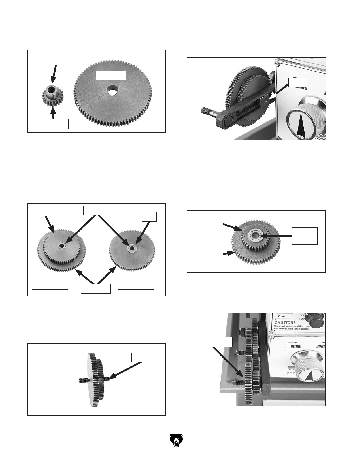
12. Remove 20T gear with keyed bushing from
80T gear (see Figure 80).
Keyed Bushing
80T Gear
20T Gear
Figure 80. 20T gear removed from 80T gear.
13. Remove keyed bushing from 20T gear.
14. Connect 80T and 60T gear with keyed bush-
ing, as shown in Figure 81. The 80T gear
hub faces out; the 60T gear hub faces the
80T gear.
16. Thread short end of 80T/60 gear shaft into
T-nut on adjuster until finger tight (see Figure
83).
T-Nut
Figure 83. 80T/60T gear threaded onto T-nut.
17. Remove 30T gear with keyed bushing from
84T gear.
18. Install 30T gear with keyed bushing onto 53T
gear (see Figure 84). Hub of 53T gear should
face 30T gear.
60T Gear
Front View Rear View
Figure 81. 80T and 60T gears connected.
15. Put dab of NLGI #2 grease onto 80T/60T
gear shaft, then insert longer end of shaft into
gear (see Figure 82).
Bushing
Hub
80T Gear
Shaft
30T Gear
Keyed
Bushing
53T Gear
Figure 84. 53T/30T gears assembled.
19. Put a dab of grease on upper shaft, then slide
53T/30T gear on, as shown in Figure 85.
53T/30T Gear
Figure 82. Shaft installed into 80T/60T gears.
-54-
Figure 85. 53T/30T gear installed on upper
shaft.
Model G0768/G0769 (Mfd. Since 6/17)
Page 61

20. Re-install e-clips and hex nuts onto middle
and top gear shafts.
21. Adjust lash between meshed gears so it
is approximately 0.003", then tighten gear
shafts and fasteners.
22. Swing adjuster up and mesh 53T gear with
40T spindle gear (see Figure 86).
Spindle Gear
Power Feed
The carriage has power feed (or automatic feed)
options for threading or non-threading operations.
This section describes how to use the power feed
option for non-threading operations. To learn how
to power the carriage for threading operations,
refer to Threading on Page 58.
53T Gear
Adjustor Cap
Screw
Figure 86. 53T gear meshed with spindle gear.
23. Secure adjuster cap screw.
24. Re-install end gear cover. The end gears are
now configured for 20 TPI.
To avoid damaging lathe, NEVER allow
cutting tool to run into chuck! ALWAYS
make sure spindle is completely stopped
BEFORE using headstock controls to make
changes.
Power Feed Controls
Use the following descriptions and figures to
understand the power feed controls.
Before using power feed, you may have to reconfigure the end gears, depending on how they are
set up (refer to Power Feed Configuration on
Page 52). The lathe comes from the factory with
the end gears set up in the power feed configuration.
A. Spindle Direction Switch: Enables forward
or reverse carriage travel when feed direction
dial and half nut lever are engaged. The carriage will not move when the switch is in the
"0" position.
Model G0768/G0769 (Mfd. Since 6/17)
A
B
Figure 87. Spindle switch and feed rate chart.
-55-
Page 62

B. Feed Rate Chart: Displays end gear settings
for selected feed rate (see Figure 88).
D. Half Nut Lever: Engages/disengages half
nut for power feed operations.
in/
40
0.0037"
A
CCD
EEF
C. Feed Direction Dial: Selects carriage travel
direction without changing direction of headstock rotation. The carriage moves left when
feed direction dial is turned right, half nut
lever is engaged, and spindle direction switch
is set to "F".
The carriage moves right when the feed
direction dial is turned to the left. The carriage
will not move when the lever is in the center
position.
84
B
20
80 80
Figure 88. Feed chart.
0.0068"
30 72
80
33 80
30
B
D
F
A
D
Figure 90. Half nut lever.
To avoid potential carriage/chuck crash,
disengage half nut lever immediately after
completing power feed operations.
Setting Power Feed Rate
Follow the example below to better understand
how to set the lathe power feed.
Tools Needed:
Hex Wrenches 4, 5mm .................................1 Ea
Open-End Wrenches 13, 14mm ...................1 Ea
Carriage travel direction reverses when the
spindle direction switch is set to "R".
C
Figure 89. Feed direction dial.
To set power feed rate to 0.0037 in/rev.:
1. DISCONNECT MACHINE FROM POWER!
2. Locate the 0.0037 in./rev. column heading on
the feed rate chart, as shown in Figure 91.
0.0037 in./rev.
in/
Change
Gears
40
0.0037"
84
B
A
CCD
EEF
Figure 91. Change gears for 0.0037 in./rev. on
20
80 80
0.0068"
30 72
80
feed chart.
30
33 80
B
D
F
A
-56-
Model G0768/G0769 (Mfd. Since 6/17)
Page 63

3. Gather the required A–F change gears: 84T,
A
40
D
B
E
F
80
72
33 80
30
0.0068"
30T, 20T and two 80T gears, based upon the
chart in Figure 91.
8. Adjust lash between meshed gears so it is
approximately 0.003", then tighten the gear
shafts.
4. Remove end cover.
5. Loosen adjuster cap screw shown in Figure
92, and pivot adjuster down to disengage
gears.
Adjustor Cap
Screw
Figure 92. Adjustor cap screw location.
6. Remove hex nuts, e-clips, and flat washers
that secure existing gears.
7. Replace A/B gear with 84T and 30T gears,
replace C/D gear with 20T and 80T gears,
and install spacer with 80T gear on bottom
shaft (see Figure 93).
9. Swing the adjuster up and mesh the 84T gear
with the spindle gear.
10. Secure the adjuster cap screw.
11. Re-install end gear cover. The lathe is now
set for a power feed rate of 0.0037 in./rev.
Threading
The following subsections describe how to use
the threading controls and charts to set up the
lathe for a threading operation. If you are unfamiliar with how to cut threads on a lathe, we strongly
recommend that you read books, review industry
trade magazines, or get formal training before
attempting any threading projects.
Headstock Threading Controls
The threading chart on the headstock face displays the settings for inch and metric threading.
Using the controls on the lathe, follow the example below to understand how to set up the lathe
for the desired threading operation.
A Gear
B Gear
0.0037"
B
F
84
20
80
C Gear
80
D Gear
A
CCD
E
30
F (Spacer)
Figure 93. Power feed change gear
E Gear
configuration.
Model G0768/G0769 (Mfd. Since 6/17)
-57-
Page 64

To set lathe to thread 20 TPI right-hand
threads:
1. Configure gears as instructed in End Gear
Configuration Example on Page 53.
2. Place the top V-belt in the A position for low
(50-1000 RPM), as shown in Figure 94.
Low
A
Top
V-Belt
High
B
Apron Threading Controls
The half nut lever engages the carriage with the
leadscrew, which moves the carriage and cutting
tool along the length of the workpiece for threading operations (see Figure 96).
Thread Dial
Chart
M
Figure 94. Top V-belt in "A" position.
3. Move the feed direction dial to the right (see
Figure 95). The lathe is now set up to cut 20
TPI threads.
Feed
Direction
Lever
Half Nut
Lever
Disengaged
Half Nut
Lever
Engaged
Figure 96. Apron threading controls.
Thread Dial
Thread Dial
The numbers on the thread dial (Figure 96) are
used with the thread dial chart to show when to
engage the half nut during inch threading.
Note: The thread dial is not used for metric
threading. For that type of operation, you must
leave the half nut engaged from the beginning
until turning is complete.
Feed Direction Dial
LEFT
(For LH threads)
Figure 95. Feed direction dial setting.
-58-
CENTER
(Neutral)
RIGHT
(for RH threads)
When threading, use slowest speed possible and avoid deep cuts, so you are able to
disengage half nut when required to prevent
a carriage crash!
When the first cutting pass is complete, the operator disengages the carriage from the leadscrew
using the half nut lever. The operator returns the
carriage for the next pass and re-engages the half
nut using the same thread dial setting to resume
the cut in the previous pass.
Model G0768/G0769 (Mfd. Since 6/17)
Page 65

Thread Dial Chart
The thread dial chart is located on the headstock,
as shown in Figure 96.
Odd TPI: For threading odd numbered TPI, use
any pair of opposite numbers on the thread dial
(see the example in Figure 99).
Find the TPI (threads per inch) that you want to
cut on the thread dial chart (see Figure 97), then
reference the scale number to the right. The scale
numbers indicate when to engage the half nut for
a specific thread pitch as indicated by the thread
dial.
INDICATOR TABLE
TPI
Odd
Even
12, 16,
20, 24,
32, 40, 44
SCALE
1, 5
1, 3, 5, 7
1–8
Figure 97. Thread dial chart.
The following examples explain how to use
the thread dial and the thread dial chart.
Any TPI: For threading any TPI, use only the
number 1 on the thread dial (see the example in
Figure 98).
Note: You can choose to use only the number
1 to cut any thread if you do not want to use the
chart, or if you forget any of the following rules.
Table Thread Dial
T.P.I. SCALE
9, 11,
13, 19
1, 5
5
3
7
1
Figure 99. Thread dial positions for odd
numbered TPI.
Even TPI Not Divisible by 4 or 8: For threading
even numbered TPI not divisible by 4 or 8, use
any numbered line on the thread dial (see the
example in Figure 100).
Table Thread Dial
T.P.I. SCALE
10, 14,
18, 22
1, 3, 5, 7
5
3
7
1
Figure 100. Any numbered line on dial for
threading even numbered TPI.
Even TPI Divisible by 4: For threading even
pitches divisible by 4, use any mark on the thread
dial (see the example in Figure 101).
Table Thread Dial
T.P.I. SCALE
Any 1
5
3
1
Figure 98. Thread dial position for any
numbered TPI.
Model G0768/G0769 (Mfd. Since 6/17)
Table Thread Dial
T.P.I. SCALE
7
12, 16,
20, 24,
32, 40,
1–8
5
3
7
1
44
Figure 101. Any mark on dial for threading even
TPI divisible by 4.
-59-
Page 66

SECTION 5: MILL OPERATIONS
The purpose of this overview is to provide the novice machine operator with a basic understanding
of how the machine is used during operation, so
the
discussed later
in this manual
Due to the generic nature of this overview, it is
not intended to be an instructional guide. To learn
more about specific operations, read this entire
manual,
training from experienced
machine operators
outside of this manual by reading "how-to" books,
trade magazines, or websites.
To reduce your risk of
serious injury, read this
entire manual BEFORE
Operation Overview
To reduce risk of injury and increase
longevity of machine, always start spindle
rotation with spindle speed dial set to lowest setting.
machine controls/components
are easier to understand.
To complete a typical milling operation, the
operator does the following:
1. Puts on personal protective equipment.
seek additional
, and do additional research
using machine.
To reduce risk of eye or face injury from
flying chips, always wear approved safety
glasses and face shield when operating this
machine.
2. Securely clamps workpiece to cross slide
table.
3. With machine disconnected from power,
installs correct tooling.
4. Adjusts mill headstock height.
5. Selects correct gear setting on milling head-
stock gearbox for desired speed range.
6. Connects machine to power.
7. Rotates spindle speed dial to lowest setting,
and resets Emergency Stop button.
8. Presses ON button, turns spindle direction
switch to "F", and rotates spindle speed dial
to correct spindle speed.
9. Uses spindle downfeed and table controls to
perform operation.
If you are not experienced with this type
of machine, WE STRONGLY RECOMMEND
that you seek additional training outside of
this manual. Read books/magazines or get
formal training before beginning any projects. Regardless of the content in this section, Grizzly Industrial will not be held liable
for accidents caused by lack of training.
-60-
10. Presses Emergency Stop button and waits
for spindle to completely stop before removing workpiece, changing tooling, or changing
spindle speeds.
Model G0768/G0769 (Mfd. Since 6/17)
Page 67
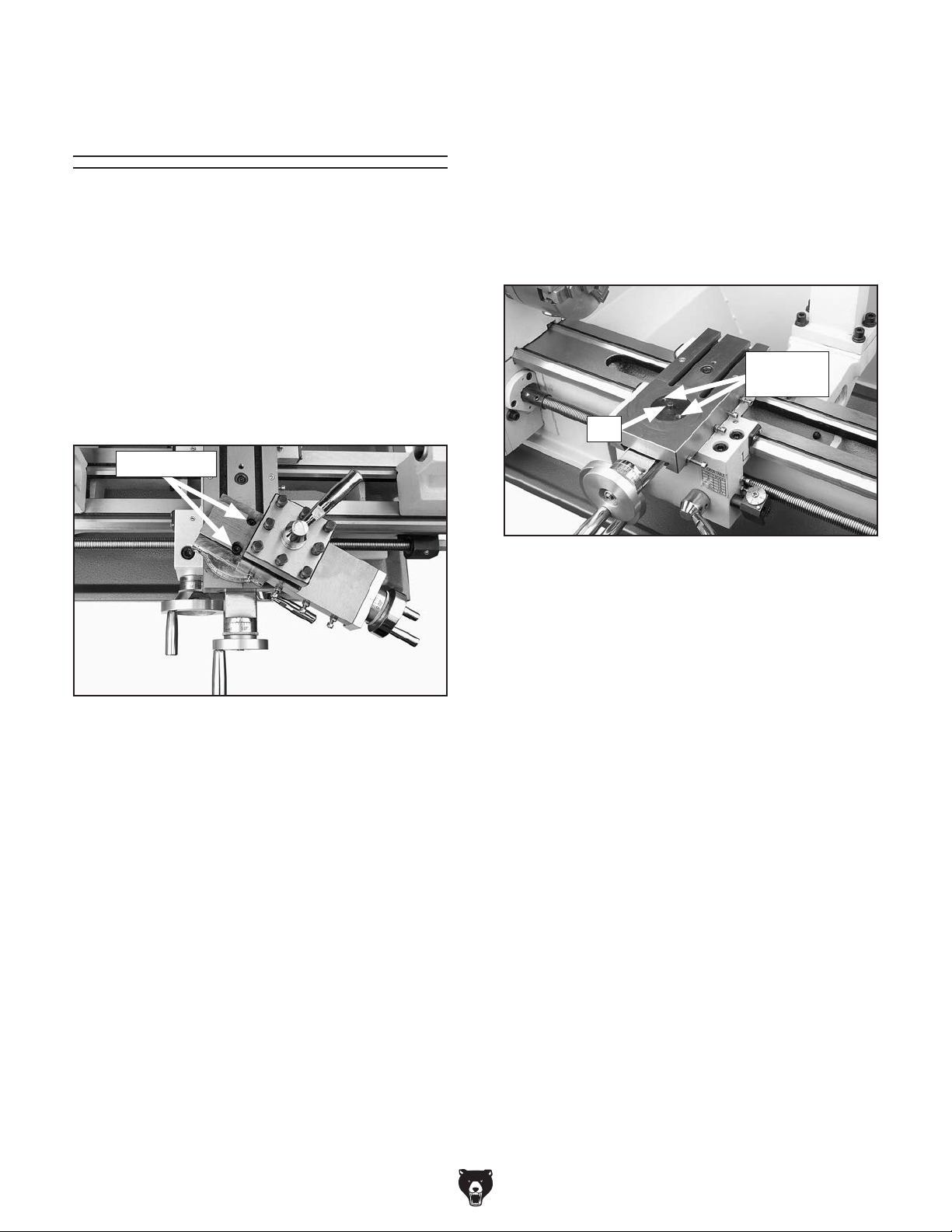
Removing
Compound Rest
Re-installing Compound Rest
Align compound rest with swivel base mounting
holes and nut (see Figure 103), then secure with
cap screws previously removed.
The compound rest and tool post must be removed
before milling/drilling so the cross slide table can
be used as the milling table.
Tools Needed Qty
Hex Wrench 3mm .............................................. 1
Hex Wrench 4mm .............................................. 1
Removing Compound Rest
Remove the two cap screws that secure compound rest (see Figure 102), then remove it.
Cap Screws
Note: While re-installing compound rest, use a
3mm hex wrench to press swivel base up from
underneath and keep it from sliding back down
into cross slide.
Mounting
Holes
Nut
Figure 103. Swivel base components.
Figure 102. Location of compound rest cap
screws.
Model G0768/G0769 (Mfd. Since 6/17)
-61-
Page 68

Headstock
Movement
Tilting Headstock
Tools Needed Qty
Wrench 16mm ................................................... 1
Wrench 14mm ................................................... 1
The milling headstock moves in the following
ways:
• Travels up and down the column (Z-axis).
• Tilts 45° left or right relative to the table.
Raising/Lowering Headstock
1. DISCONNECT MACHINE FROM POWER!
2. Loosen both Z-axis lock levers shown in
Figure 104.
Z-Axis
Lock
Levers
Figure 104. Location of Z-Axis lock levers.
To tilt headstock:
1. DISCONNECT MACHINE FROM POWER!
2. Support headstock with one hand, then loos-
en headstock center bolt and angle lock nut
(see Figure 106).
Center
Bolt
Angle
Tilt Scale
Figure 106. Headstock tilt controls.
3. While viewing tilt scale, rotate headstock to
required angle, then retighten center bolt and
angle lock nut to secure headstock.
Lock Nut
3. Use vertical handwheel shown in Figure 105
to adjust headstock height.
Vertical
Handwheel
Figure 105. Location of Z-Axis handwheel.
4. Retighten lock levers.
-62-
Model G0768/G0769 (Mfd. Since 6/17)
Page 69

Table Travel
The cross slide table travels in two directions, as
illustrated in Figure 107:
• X-axis (longitudinal)
• Y-axis (cross)
Carriage Handwheel (X-Axis)
Graduated Dial
Increments ................................... 0.01" (0.25mm)
One Full Revolution .......................... 1" (25.4mm)
Use the carriage handwheel to move the carriage
left or right along the bed. Adjust the position of
the graduated scale by holding the handwheel
with one hand and turning the dial with the other.
X-Axis or Longitudinal Travel (Left & Right)
Y-Axis or
Cross Travel
(In & Out)
Figure 107. Possible directions of cross slide
travel.
These movements are controlled by the carriage
handwheel and cross slide handwheel, (see
Figure 108).
Carriage
Handwheel
(X-Axis)
Cross Slide
Table
Cross Slide
Handwheel
(Y-Axis)
Cross Slide Handwheel (Y-Axis)
Graduated Dial
Increments ................................. 0.002" (0.05mm)
One Full Revolution .....................0.08" (2.03mm)
Use this handwheel to move the cross slide table
toward or away from the tooling. The cross slide
handwheel has a direct-read graduated dial,
which will read twice the actual table cross feed
travel.
Figure 108. Table travel controls.
Model G0768/G0769 (Mfd. Since 6/17)
-63-
Page 70

Using Spindle
Downfeed Controls
The Model G0769 features two different types of
spindle downfeed controls: coarse and fine, as
shown in Figure 109.
Fine
Downfeed
Handwheel
Coarse
Downfeed
Handle
Fine Downfeed
Fine downfeed is typically used for milling applications, because the spindle only moves up or down
when the fine downfeed handwheel (see Figure
109) is rotated (there is no automatic spindle
return to the top position, as with the coarse
downfeed controls). This allows the spindle height
to be locked in place for precise Z-axis positioning
of a cutter or end-mill when milling a flat surface
across the face of a workpiece. In order to ensure
the milled surface remains flat, the spindle height
cannot move until the entire milling operation is
complete.
Quill Lock
Lever
Downfeed
Selector
Knob
Graduated Dials
Figure 109. Spindle controls.
Coarse Downfeed
Coarse downfeed is typically used for drilling
applications. Rotate either of the coarse downfeed
handles (see Figure 109) to lower the spindle,
and an internal coil spring helps raise the spindle
back to the top position when you stop applying
downward pressure on the handle.
Note: To maintain control of the upward spindle
travel and the rotating bit in your workpiece,
always continue holding the handle until the
spindle returns to the top position. Letting go of
the coarse downfeed handles when the spindle
is in the lowered position will cause the spindle to
retract too quickly and slam up into the headstock
or lift the workpiece and cause it to spin out of
control.
The coarse downfeed hub features a graduated
dial that measures spindle movement in 0.02"
increments, with one full revolution equaling 2.00"
of spindle travel.
The fine downfeed graduated dial measures spindle movement in 0.001" increments, with one full
revolution equaling 0.080" of spindle travel.
Engaging Fine Downfeed Controls
In the following example, the fine downfeed
controls are used to mill 0.010" off a workpiece:
1. Use vertical travel handwheel (see Figure
105 on next page) to adjust cutting tool just
above workpiece surface, then secure the
headstock with Z-axis lock levers.
2. Tighten downfeed selector knob (see Figure
109) to engage fine downfeed handwheel.
3. Loosen quill lock lever.
4. Rotate fine downfeed handwheel clockwise
and lower cutting tool so it just touches
workpiece.
5. Move workpiece out of the way.
6. Using graduated dial to gauge spindle move-
ment, rotate fine downfeed handwheel clockwise 0.010".
7. Tighten quill lock lever.
8. Turn mill/drill ON and perform cutting pass.
-64-
Model G0768/G0769 (Mfd. Since 6/17)
Page 71

Installing/Removing
3. Insert tooling into spindle until in contacts
drawbar.
Tooling
The Model G0769 includes a 1⁄2 " drill chuck with
MT#2 arbor (see Figure 110).
1
Figure 110.
⁄2" chuck joined with MT#2 arbor.
Cutting tools are sharp and
can easily cause cutting
injuries. Always protect
your hands with leather
gloves or shop rags when
handling cutting tools.
4. Working from top, thread drawbar by hand
into tooling until it is snug (see Figure 112).
Figure 112. Threading drawbar into tooling.
5. Tighten drawbar.
Note: Do not overtighten drawbar.
Overtightening makes tool removal difficult
and will damage arbor and threads.
6. Tighten drawbar lock nut, as shown in Figure
113.
Installing Tooling
Tools Needed Qty
Wrench 8mm ..................................................... 1
Wrench 17mm.................................................... 1
Wrench 25mm ................................................... 1
To install tooling:
1. DISCONNECT MACHINE FROM POWER!
2. Remove drawbar cap (see Figure 111).
Drawbar Cap
Figure 111. Location of drawbar cap.
Drawbar
Locknut
Figure 113. Tightening drawbar lock nut.
7. Re-install drawbar cap.
Model G0768/G0769 (Mfd. Since 6/17)
-65-
Page 72

Removing Tooling
Tools Needed Qty
Wrench 8mm ..................................................... 1
Wrench 17mm.................................................... 1
Wrench 25mm ................................................... 1
Brass Hammer .................................................. 1
To remove tooling:
1. DISCONNECT MACHINE FROM POWER!
2. Remove drawbar cap.
3. Loosen drawbar lock nut (see Figure 113) on
previous page.
5. Tap top of drawbar with hammer to unseat
taper (see Figure 114).
4. Unthread drawbar from tooling one full rotation.
Note: Do not fully unthread tooling from
drawbar or the drawbar and tool threads
could be damaged in the next step.
Figure 114. Tapping drawbar to unseat tool
taper.
6. Hold onto tooling with one hand and fully
unthread drawbar.
-66-
Model G0768/G0769 (Mfd. Since 6/17)
Page 73

Spindle Speed
Using the correct spindle speed is important for
safe and satisfactory results, as well as maximizing tool life.
To set the mill spindle speed for operation, you will
need to: 1) Determine the best spindle speed for
the cutting/drilling task, and 2) configure the high/
low gearbox knob for the desired speed range,
3) use the spindle speed dial and spindle speed
RPM display to get the spindle speed.
Determining Spindle Speed
Many variables affect the optimum spindle speed
to use for any given operation, but the two most
important are the recommended cutting speed
for the workpiece material and the diameter of
the cutting tool, as noted in the formula shown in
Figure 115.
Setting Spindle Speed
1. Rotate spindle speed dial all the way coun-
terclockwise to set spindle speed to lowest
value.
2. Rotate high/low gearbox knob (see Figure
116) to either “L” (spindle speeds 50–100
RPM) or “H” (spindle speeds 100–2000
RPM).
Note: When switching between gears, it may
be necessary to rotate spindle by hand so
gears will align and engage.
Gearbox
Knob
*Recommended
Cutting Speed (FPM) x 12
Tool Dia. (in inches) x 3.14
Spindle
=
Speed
(RPM)
*Double if using carbide cutting tool
Figure 115. Spindle speed formula for mill/drills.
Cutting speed, typically defined in feet per minute
(FPM), is the speed at which the edge of a tool
moves across the material surface.
A recommended cutting speed is an ideal speed
for cutting a type of material in order to produce
the desired finish and optimize tool life.
The books Machinery’s Handbook or Machine
Shop Practice, and some internet sites, provide excellent recommendations for which cutting
speeds to use when calculating the spindle speed.
These sources also provide a wealth of additional
information about the variables that affect cutting
speed and they are a good educational resource.
Gearbox Knob
L
(Low)
Figure 116. High/low gearbox knob set to low
3. Press ON button and turn spindle direction
switch to "F".
4. While watching RPM display, rotate spindle
speed dial clockwise until desired RPM is
reached.
CENTER
(Neutral)
"L".
H
(High)
Also, there are a large number of easy-to-use
spindle speed calculators that can be found on
the internet. These sources will help you take into
account the applicable variables in order to determine the best spindle speed for the operation.
Model G0768/G0769 (Mfd. Since 6/17)
-67-
Page 74

ACCESSORIES
order online at www.grizzly.com or call 1-800-523-4777
Installing unapproved accessories may
SECTION 6: ACCESSORIES
cause machine to malfunction, resulting in
serious personal injury or machine damage.
To reduce this risk, only install accessories
recommended for this machine by Grizzly.
NOTICE
Refer to our website or latest catalog for
additional recommended accessories.
5
T25206—11 Pc. Carbide Bit Set
This 11-Pc. Carbide-Tipped Tool Bit Set includes
a wide variety of tool types for just about any
machining operation. This set also includes two
boring bars. Boring bars measure 4
Shank size for all is
5
⁄16".
⁄16"
7
⁄8" long.
T26599—Optional Stand for G0768/G0769
• Size: 29
• Drawers: 12" W x 8" H x 12" D
Figure 119. T26599 Stand for G0768/G0769.
SB1365—South Bend Way Oil-ISO 68
T23964—Moly-D Multi-purpose NLGI#2
Grease
1
⁄2" W x 32" H x 16" D
Figure 117. T25206 11-Pc. carbide-tipped tool
set.
H2987—½" Bent Lathe Dog
H2988—1" Bent Lathe Dog
H2989—1½" Bent Lathe Dog
H2990—2" Bent Lathe Dog
H2991—3" Bent Lathe Dog
Figure 118. Model H2987 1⁄2" Bent Lathe Dog.
-68-
Figure 120. Recommended products for
machine lubrication.
Model G0768/G0769 (Mfd. Since 6/17)
Page 75

order online at www.grizzly.com or call 1-800-523-4777
G9361—Heavy-Duty Triple Bearing Live Center
MT#2
This Triple Bearing Live Center is hardened to
61-65 Rockwell and has a unique head driving
mechanism that prevents dust, chips, and coolant
from entering the internal workings. Made with
precision, high-quality bearings, this live center
has an accuracy of 0.0003".
Figure 121. G9361 MT#2 Live Center.
G9788—4-Pc. Measuring Tool Set
This is the set you need for accurate measurements. Includes a stainless steel 6" dial caliper, a
6" scale with inch scale on one side and a metric
scale on the other, a 1" carbide-tipped micrometer with vernier scale, and a 4" precision square
with beveled edge. Comes with molded case and
micrometer adjustment wrench.
H7991—Mini Mag Base Indicator Set
Set features a 7 Jewel indicator with 0.0005" reso-
3
lution. The mini magnetic base measures 1
3
⁄16" x 13⁄8" and includes a single lock knob for
1
⁄16" x
easy setups. Includes 2 dovetail tool posts and a
protective plastic case.
Figure 123. H7991 Mini Mag Base Indicator Set.
H5930—4-Pc. Center Drill Set 60°
H5931—4-Pc. Center Drill Set 82°
Double-ended HSS Center Drills are precision
ground. Each set includes sizes 1–4.
SIZE
1
2
3
4
BODY
DIA.
1
⁄8"
3
⁄16"
1
⁄4"
5
⁄16"
DRILL
OVERALL
DIA.
3
⁄64" 11⁄4"
5
⁄64" 17⁄8"
7
⁄64"
1
⁄8" 21⁄8"
LENGTH
2"
Figure 122. G9788 4-Pc. Measuring Tool Set.
Figure 124. HSS ground center-drill sets.
Model G0768/G0769 (Mfd. Since 6/17)
-69-
Page 76

order online at www.grizzly.com or call 1-800-523-4777
T10253 —2" Mini Self-Centering Vise with
Swivel Base
Ideal for holding small parts and model making.
Has self-centering jaws and adjustable gib on a
1
dovetailed way. 2
5
⁄8" crank handle, and base swivels 360°. Overall
2
size is 6
3
⁄4" L x 4" W x 33⁄8" H with handle removed.
⁄16" jaw opening, 2" jaw width,
H6195—3" Rotary Table w/ Clamps
For horizontal or vertical use. 3" diameter table
rotates 360°. Low profile—only 1.670" tall. 4
T-slots. 1:36 ratio or 10° per handwheel revolution.
Scale reads to 15 minutes. Has brass lock knob.
Table height in horizontal position: 1
1
in vertical position: 3
⁄4".
5
Figure 125. T10253 2" Mini Self-Centering Vise. Figure 127. H6195 3" Rotary Table w/Clamps.
5
⁄16"
⁄8";
4-Flute C-2 Grade Carbide End Mills
These American-made 4-flute Carbide End Mills
feature standard cutting lengths and nominal
minus diameter tolerances. Recommended for
profiling and finishing non-ferrous materials.
Model
H3649
H3650
H36 51
H3652
H3653
H3654
H3655
H3656
H3657
H3658
H3659
H3660
Cutting
Dia.
1
⁄16"
3
⁄32"
1
⁄8"
5
⁄32"
3
⁄16"
7
⁄32"
1
⁄4"
9
⁄32"
5
⁄16"
3
⁄8"
7
⁄16" 1" 23⁄4"
1
⁄2 " 1" 3"
Flute Lgth OA Lgth
3
⁄16" 11⁄2 "
3
⁄8" 11⁄2 "
1
⁄2 " 11⁄2 "
9
⁄16" 2"
5
⁄8" 2"
5
⁄8" 21⁄2 "
3
⁄4" 2
3
⁄4" 21⁄2 "
13
⁄16" 21⁄2 "
7
⁄8" 21⁄2 "
1
⁄2 "
MT#2 End Mill Holders
Hold your end mills in the Model G0769 spindle
with these quality end mill holders. Sized for various end mill shanks.
Model MT Drawbar Size
T25703 #2
T25704 #2
T25705 #2
T25706 #2
3
⁄8"-16 TPI
3
⁄8"-16 TPI
3
⁄8"-16 TPI
3
⁄8"-16 TPI
3
⁄16"
3
1
5
⁄8"
⁄2 "
⁄8"
Figure 128. MT#2 end mill holders.
Figure 126. 4-flute C-2 grade carbide end mills.
-70 -
Model G0768/G0769 (Mfd. Since 6/17)
Page 77

SECTION 7: MAINTENANCE
Daily, After Operations
• Press the Emergency Stop button (to prevent
Always disconnect power
to the machine before
performing maintenance.
Failure to do this may
result in serious personal injury.
Schedule
accidental startup).
• Vacuum/clean all chips and swarf from bed,
slides.
• Wipe down all unpainted or machined surfaces with an oiled rag.
Every 90 Hours of Operation
• Lubricate quill rack—G0769 Only (Page 75).
• Lubricate headstock gears—G0769
(Page 76).
Ongoing
To maintain a low risk of injury and proper
machine operation, if you ever observe any of the
items below, shut down the machine immediately
and fix the problem before continuing operations:
• Loose mounting bolts or fasteners.
• Worn, frayed, cracked, or damaged wires.
• Guards or covers removed.
• Emergency Stop button not working correctly
or not requiring you to reset it before starting
the machine again.
• Damaged or malfunctioning components.
Daily, Before Operations
• Add oil to the ball oilers (Page 72).
• Lubricate the leadscrew and carriage rack
(Page 73).
• Lubricate the bedways (Page 73).
• Clean/lubricate the cross slide and compound slide (Page 73).
• Disengage the half nut on the carriage (to
prevent crashes upon startup).
• Lubricate column ways—G0769 Only (Page
75).
• Lubricate quill outside surface—G0769 Only
(Page 75).
Every 120 Hours of Operation
• Lubricate Z-axis leadscrew—G0769 Only
(Page 76).
Annually
• Lubricate end gears (Page 74).
Cleaning/Protecting
Because of its importance, we recommend that
the cleaning routine be planned into the workflow
schedule.
Typically, the easiest way to clean swarf from the
machine is to use a brush and wet/dry shop vacuum that are dedicated for this purpose. The small
chips left over after vacuuming can be wiped up
with a slightly oiled rag. Avoid using compressed
air to blow off chips, as this may drive them deeper into the moving surfaces or cause sharp chips
to fly into your face or hands.
All unpainted and machined surfaces should be
wiped down daily to keep them rust free and in top
condition. This includes any surface that is vulnerable to rust if left unprotected. Use a quality ISO
68 way oil (see Page 68 for offerings from Grizzly)
to prevent corrosion.
Model G0768/G0769 (Mfd. Since 6/17)
-71-
Page 78

Lubrication
The lathe has metal-to-metal sliding surfaces that
require regular lubrication to maintain smooth
movement and ensure long-lasting operation.
Other than the lubrication points covered in this
section, all other bearings are internally lubricated
and sealed at the factory. Simply leave them
alone unless they need to be replaced.
Before performing any lubrication task,
DISCONNECT MACHINE FROM POWER!
We recommend using Model SB1365 Way Oil
or equivalent (see Page 68) for most lubrication
tasks.
Lubrication Frequency
Items Needed Qty
Clean Rag ........................................ As Needed
Mineral Spirits .................................... As Needed
Stiff Brush .......................................................... 1
Pump-Type Oil Can w/Plastic Cone Tip ............ 1
Ball Oilers
Lube Type ............................... ISO 32 Equivalent
Lube Amount ............................ 1 or 2 Squirts/Fill
Lubrication Frequency ................................. Daily
This lathe has four ball oilers that should be oiled
on a daily basis before beginning operation.
Proper lubrication of ball oilers is done with a
pump-type oil can that has a plastic or rubberized cone tip. We do not recommend using metal
needle or lance tips, as they can push the ball too
far into the oiler, break the spring seat, and lodge
the ball in the oil galley.
Lubrication Task Frequency Page
Ball Oilers Daily
Leadscrew & Carriage
Rack
Bedways Daily
Feed Gearbox Annually
Cross Slide & Compound
Slide
End Gears Annually
Mill Column Ways Daily
Mill Quill Outside Surface Daily
Mill Quill Rack 90 Hrs.
Mill Z-Axis Leadscrew 120 Hrs.
Mill Headstock Gears 90 Hrs.
Daily
Daily
This
Page
73
73
73
73
74
75
75
75
76
76
NOTICE
The recommended lubrication is based on
light-to-medium usage. Since lubrication
helps to protect value and operation of
machine, these lubrication tasks may need
to be performed more frequently than recommended, depending on usage.
Lubricate the ball oilers before and after machine
use, and more frequently under heavy use. When
lubricating ball oilers, first clean the outside surface to remove any dust or grime. Push the tip of
the oil can nozzle against the ball oiler to create
a hydraulic seal, then pump the oil can once or
twice. If you see sludge and contaminants coming
out of the lubrication area, keep pumping the oil
can until the oil runs clear. When finished, wipe
away any excess oil.
Refer to Figure 129 to identify the location of each
ball oiler.
Ball Oilers
Ball Oilers
Figure 129. Ball oilers.
Failure to follow reasonable lubrication
practices as instructed in this manual could
lead to premature failure of machine components and will void the warranty.
-72-
Model G0768/G0769 (Mfd. Since 6/17)
Page 79

Leadscrew & Carriage Rack
Lube Type . . Model SB1365 or ISO 68 Equivalent
Lube Amount ..................................... As Needed
Lubrication Frequency ................................. Daily
Before lubricating the leadscrew and carriage
rack (see Figure 130), clean them first with mineral spirits. Use a stiff brush to help remove any
debris or grime. Apply a thin coat of oil along the
entire length of the carriage rack. Use a stiff brush
to make sure oil is applied into the leadscrew
threads.
Note: In some environments, abrasive material
can become caught in the leadscrew lubricant and
drawn into the half nut. In this case, lubricate the
leadscrew with a quality dry lubricant.
Feed Gearbox
Lube Type . . Model T23964 or NLGI#2 Equivalent
Frequency ....................... Annually or As Needed
The gearbox can be quickly lubricated (as
necessary or if noisy) by removing the set screw
shown in Figure 109 and adding a shot or two of
grease from a grease gun. The grease inside the
gearbox will eventually need to be replaced. To do
this, remove the gearbox cover, use mineral spirits
and a stiff brush to clean gears, allow them to dry,
reapply new grease, and re-install cover.
Feed Gearbox
Set
Screw
Rack
Leadscrew
Figure 130. Leadscrew, rack and bedways.
Bedways
Bedways
Lube Type . . Model SB1365 or ISO 68 Equivalent
Lube Amount ..................................... As Needed
Lubrication Frequency ................................. Daily
Before lubricating the bedways (see Figure 130),
clean them with mineral spirits. Apply a thin coat
of oil along the length of the bedways. Move the
steady rest, carriage, and tailstock to access the
entire length of the bedways.
Figure 131. Feed gearbox quick lubrication
location.
Cross Slide & Compound Slide
Lube Type . . Model SB1365 or ISO 68 Equivalent
Lube Amount ........................................Thin Coat
Lubrication Frequency ................................. Daily
Use the handwheels to separately move the
cross slide and compound rest as far forward as
possible (see Figure 132). Clean the slides with
mineral spirits and wipe down with a rag. Apply
lubricant and move the slides back and forth to
distribute the oil.
Compound
Bottom Slide
Model G0768/G0769 (Mfd. Since 6/17)
Cross Slide
Bottom Slide
Figure 132. Location of bottom slides.
-73 -
Page 80

End Gears
Lube Type . . Model T23964 or NLGI#2 Equivalent
Frequency ............... Annually or When Changing
The end gears, shown in Figure 133, should
always have a thin coat of heavy grease to
minimize corrosion, noise, and wear. Wipe away
excess grease that could be thrown onto the
V-belts and reduce optimal power transmission
from the motor.
Figure 133. End gears.
Handling & Care
Make sure to clean and lubricate any gears you
install or change. Be very careful during handling
and storage—the grease coating on the gears will
easily pickup dirt or debris, which can then spread
to the other gears and increase the rate of wear.
Lubricating
1. DISCONNECT MACHINE FROM POWER!
2. Remove end gear cover and all end gears
shown in Figure 133.
3. Clean end gears thoroughly with mineral spir-
its to remove old grease. Use a small brush if
necessary to clean between teeth.
4. Clean shafts, and wipe away any grease
splatters in vicinity and on inside of end
cover.
5. Using a clean brush, apply a thin layer of
white lithium grease on the gears. Make sure
to get grease between gear teeth, but do not
fill teeth valleys.
6. Apply a small dab of grease to each gear
shaft.
7. Install end gears and mesh them together
with an approximate 0.002"–0.004" backlash.
Once gears are meshed together, apply a
small dab of grease between them where
they mesh together—this grease will be distributed when gears rotate and re-coat any
areas scraped off during installation.
8. Re-install end cover before re-connecting
machine to power.
Make sure the end cover remains installed whenever possible to keep the gears free of dust or
debris from the outside environment.
-74 -
Model G0768/G0769 (Mfd. Since 6/17)
Page 81

Column Ways (G0769)
Lube Type . . Model SB1365 or ISO 68 Equivalent
Lube Amount ........................................Thin Coat
Lubrication Frequency ................................. Daily
Quill Rack
Lube Type . . Model T23964 or NLGI#2 Equivalent
Lube Amount ........................................Thin Coat
Lubrication Frequency ......... 90 hrs. of Operation
Regular lubrication will ensure your milling headstock performs at its highest potential. Regularly
wipe table and column ways with recommended
lubrication, then move components back and
forth several times to ensure smooth movements
(see Figure 134).
Z-Axis Ways
(1 of 2)
Figure 134. Z-axis way lubrication location.
Quill Outside Surface
Lube Type . . Model SB1365 or ISO 68 Equivalent
Lube Amount ........................................Thin Coat
Lubrication Frequency ................................. Daily
Move quill all the way down to gain full access to
quill rack (see Figure 136), lock the quill in place,
then clean teeth with mineral spirits, shop rags,
and a brush.
Rack
Figure 136. Quill rack location.
When dry, use a brush to apply a thin coat of
grease to teeth, then raise/lower the quill several
times to evenly distribute grease.
Note: Re-apply oil that may have been removed
during the cleaning process to the quill surface
around the rack.
Without disturbing grease on quill rack, clean outside smooth surface of quill (see Figure 135) with
mineral spirits and shop rags.
Quill Outside
Surface
Figure 135. Outside surface of quill.
When dry, apply thin coat of lubricant to smooth
surface, then move spindle up and down to evenly
distribute oil.
Model G0768/G0769 (Mfd. Since 6/17)
-75 -
Page 82

Z-Axis Leadscrew (G0769)
Lube Type . . Model T23964 or NLGI#2 Equivalent
Lube Amount ........................................Thin Coat
Lubrication Frequency ....... 120 hrs. of Operation
3
Lower headstock approximately
down the Z-axis ways, as shown in Figure 137.
⁄4 of the way
Headstock Gears (G0769)
Lube Type . . Model T23964 or NLGI#2 Equivalent
Lube Amount ........................................Thin Coat
Lubrication Frequency ......... 90 hrs. of Operation
To lubricate headstock gears:
1. Remove cap screw and headstock gear
access cover, as shown in Figure 138.
Z-Axis
Leadscrew
Figure 137. Z-axis leadscrew location.
Use mineral spirits and a brush to clean as much
existing grease and debris off of Z-axis leadscrew
shown in Figure 137 as possible. When dry, apply
NLGI#2 grease to exposed leadscrew threads.
Move headstock through its full range of motion
several times to disperse grease along full length
of leadscrew.
Headstock
Cap Screw
Figure 138. Headstock access cover and cap
screw location.
2. Using small brush, apply thin coat of grease
to headstock gears.
3. Operate mill/drill in both high and low gear
settings to work grease through gears.
4. Re-install access cover and cap screw
removed in Step 1.
Gear
Access
Cover
Headstock
Gears
-76 -
Model G0768/G0769 (Mfd. Since 6/17)
Page 83

Machine Storage
To prevent the development of rust and corrosion,
the lathe must be properly prepared if it will be
stored for a long period of time. Doing this will
ensure the lathe remains in good condition for
later use.
Preparing Machine for Storage
1. DISCONNECT MACHINE FROM POWER!
2. Thoroughly clean all unpainted, bare metal
surfaces, then apply a liberal coat of way
oil, heavy grease, or rust preventative. Take
care to ensure these surfaces are completely
covered and that rust preventative or grease
is kept off of painted surfaces.
3. Lubricate machine as outlined in lubrication
section. Be sure to use an oil can to purge all
ball oilers and oil passages with fresh oil.
Bringing Machine Out of Storage
1. Remove moisture-absorbing desiccant packs
from electrical box.
2. Repeat Test Run and Spindle Break-In procedures, beginning on Page 27.
4. Place a few moisture absorbing desiccant
packs inside electrical box.
5. Cover machine and place it in a dry area that
is out of direct sunlight and away from hazardous fumes, paint, solvents, or gas. Fumes
and sunlight can bleach or discolor paint.
6. Every few months, rotate by hand all geardriven components a few times in several
gear selections. This will keep bearings,
bushings, gears, and shafts well lubricated
and protected from corrosion—especially
during winter months.
Slide carriage, tailstock, and steady rest down
lathe bed to make sure that way spotting is
not beginning to occur. Move mill headstock
up and down column (Model G0769 only).
Model G0768/G0769 (Mfd. Since 6/17)
-77-
Page 84

Review the troubleshooting procedures in this section if a problem develops with your machine. If you need
the
serial number and manufacture date of your machine before calling.
SECTION 8: SERVICE
replacement parts or additional help with a procedure, call our Technical Support. Note: Please gather
Troubleshooting
Motor & Electrical
Symptom Possible Cause Possible Solution
Machine does not
start or a circuit
breaker trips.
Machine stalls or is
underpowered.
Machine has
vibration or noisy
operation.
1. Emergency stop button engaged or at fault.
2. Incorrect power supply voltage.
3. Blown fuse.
4. Power supply circuit breaker tripped or fuse
blown.
5. Wiring open/has high resistance.
6. On/Off switch at fault.
7. Spindle speed dial in OFF position or at
fault.
8. Spindle direction switch turned to "0" or at
fault.
9. Lathe/mill selector switch in neutral, or at
fault.
10. Motor brushes at fault.
11. Motor at fault.
12. Spindle rotation switch at fault.
1. Machine undersized for task.
2. Feed rate/cutting speed too fast.
3. Wrong workpiece material.
4. Timing belt slipping.
5. Motor overheated.
6. Computer board at fault.
7. Motor speed dial at fault.
8. Motor brushes at fault.
9. Pulley/sprocket slipping on shaft.
10. Motor bearings at fault.
11. Motor at fault.
1. Motor or component loose.
2. Bit chattering.
3. V-belt(s) worn or loose.
4. Motor fan rubbing on fan cover.
5. Motor mount loose/broken.
1. Press side tab in and lift switch cover. Press On
button to reset; replace if not working properly.
2. Ensure correct power supply voltage.
3. Replace fuse/ensure no shorts (Page 85).
4. Ensure circuit is sized correctly and free of shorts.
Reset circuit breaker or replace fuse.
5. Check/fix broken, disconnected, or corroded wires.
6. Replace switch.
7. Turn spindle speed dial past "0". Ensure dial has
correct voltage. Replace if faulty.
8. Turn spindle direction switch to "F" or "R". Ensure
dial has correct voltage. Replace if faulty.
9. Turn lathe/mill selector switch to "lathe" or "mill"
mode. Replace if faulty.
10. Remove/replace brushes (Page 86).
11. Test/repair/replace.
12. Test/replace switch.
1. Use sharp bits/chisels at correct angle; reduce feed
rate/depth of cut; use coolant if possible.
2. Decrease feed rate/cutting speed.
3. Use correct type/size of metal.
4. Tension/replace belt; ensure pulleys are aligned.
5. Use sharp bits; reduce feed rate/depth of cut.
6. Clean motor, let cool, and reduce workload.
7. Test and replace if at fault.
8. Remove/replace brushes (Page 86).
9. Replace loose pulley/shaft.
10. Test by rotating shaft; rotational grinding/loose shaft
requires bearing replacement.
11. Test/repair/replace.
1. Inspect/replace damaged bolts/nuts, and retighten
with thread locking fluid.
2. Replace/sharpen bit; index bit to workpiece; use
correct feed rate and cutting RPM; retract tool
holder and position workpiece closer.
3. Inspect/replace belts with a new matched set.
4. Fix/replace fan cover; replace loose/damaged fan.
5. Tighten/replace.
-78 -
Model G0768/G0769 (Mfd. Since 6/17)
Page 85

Lathe Operation
Symptom Possible Cause Possible Solution
Bad surface finish. 1. Wrong spindle speed or feed rate.
2. Dull tooling or poor tool selection.
3. Tool height not at spindle centerline.
4. Too much play in gibs.
Tapered tool difficult
to remove from
tailstock quill.
Cross slide,
compound rest, or
carriage feed has
sloppy operation.
Cross slide,
compound,
or carriage
handwheels hard to
move.
Cutting tool
or machine
components vibrate
excessively during
cutting.
Workpiece is
tapered.
Chuck jaws will
not move or do not
move easily.
1. Quill not fully retracted into tailstock.
2. Contaminants not removed from taper
before inserting into quill.
1. Ways loaded with shavings, dust, or grime.
2. Gibs are out of adjustment.
3. Handwheel loose or excessive backlash.
4. Leadscrew mechanism worn or out of
adjustment.
1. Ways loaded with chips, dust, or grime.
2. Gibs are too tight.
3. Backlash setting too tight.
4. Bedways are dry.
5. Half nut lever engaged.
1. Tool holder not tight enough.
2. Cutting tool sticks too far out of tool holder;
lack of support.
3. Gibs are out of adjustment.
4. Dull cutting tool.
5. Incorrect spindle speed or feed rate.
1. Headstock and tailstock not properly
aligned.
1. Chips lodged in jaws or scroll plate. 1. Remove jaws, clean and lubricate scroll plate, then
1. Adjust for appropriate spindle speed and feed rate.
2. Sharpen tooling or select a better tool for the
intended operation.
3. Adjust tool height to spindle centerline (see Page
45).
4. Tighten gibs (see Page 83).
1. Turn quill handwheel until tapered tool is forced out
of quill.
2. Clean taper and bore, then re-install tool.
1. Clean ways and relubricate.
2. Adjust gibs (see Page 83).
3. Tighten handwheel fasteners, adjust handwheel
backlash to a minimum (see Page 82).
4. Adjust leadscrew to remove end play (see Page
82).
1. Clean ways and lubricate.
2. Loosen gibs slightly (see Page 83).
3. Slightly loosen backlash setting (see Page 82).
4. Lubricate bedways.
5. Disengage half nut lever for manual feeding.
1. Check for debris, clean, and retighten.
2. Re-install cutting tool so no more than
length is sticking out of tool holder.
3. Adjust gibs at affected component (see Page 83).
4. Replace or resharpen cutting tool.
5. Use the recommended spindle speed and feed rate.
1. Re-align tailstock to headstock spindle centerline
(see Page 39).
replace jaws.
1
⁄3 of the total
Model G0768/G0769 (Mfd. Since 6/17)
-79 -
Page 86

Mill Operation
Symptom Possible Cause Possible Solution
Tool slips in spindle. 1. Tool is not fully drawn up into spindle taper.
2. Debris on tool or in spindle taper.
3. Taking too big of cut.
Breaking tools or
cutters.
Workpiece vibrates
or chatters during
operation.
Cross slide table is
hard to move.
Bad surface finish. 1. Spindle speed/feed rate is too fast.
1. Spindle speed/feed rate is too fast.
2. Cutting tool too small.
3. Cutting tool getting too hot.
4. Taking too big of a cut.
5. Spindle extended too far down.
1. Workpiece not secure.
2. Spindle speed/feed rate is too fast.
3. Spindle extended too far down.
1. Chips have loaded up on ways.
2. Ways are dry and need lubrication.
3. Gibs are too tight.
2. Using dull or incorrect cutting tool.
3. Wrong rotation of cutting tool.
4. Workpiece not secure.
5. Spindle extended too far down.
1. Tighten drawbar (Do not overtighten).
2. Clean collet and spindle taper.
3. Lessen depth of cut and allow chips to clear.
1. Set spindle speed correctly (Page 67) or use slower
feed rate.
2. Use larger cutting tool and slower feed rate.
3. Use coolant fluid or oil for appropriate application if
possible.
4. Lessen depth of cut and allow chips to clear.
5. Fully retract spindle and lower headstock. This
increases rigidity.
1. Properly clamp workpiece on table or in vise.
2. Set spindle speed correctly (Page 67) or use slower
feed rate.
3. Fully retract spindle and lower headstock. This
increases rigidity.
1. Frequently clean away chips that load up during
milling operations.
2. Lubricate ways (Page 73).
3. Adjust gibs (see Page 83
1. Set spindle speed correctly (Page 67) or use a
slower feed rate.
2. Sharpen cutting tool or select one that better suits
operation.
3. Check for proper cutting rotation for cutting tool.
4. Properly clamp workpiece on table or in vise.
5. Fully retract spindle and lower headstock. This
increases rigidity.
).
-80-
Model G0768/G0769 (Mfd. Since 6/17)
Page 87

Tensioning &
Replacing V-Belts
V-belts stretch and wear with use, so it is important to routinely monitor belt tension. V-belts that
are improperly tensioned or exposed to grease/oil
will slip and poorly transmit power from the motor.
To ensure optimal power transmission, inspect
belts on a monthly basis to verify they are properly
tensioned and free of oil/grease. Replace V-belts
when they become cracked, frayed, or glazed.
Tools Needed Qty
Hex Wrench 3, 4mm ....................................1 Ea.
Open-End Wrench 10, 13 mm .....................1 Ea.
To adjust tension or replace V-belts:
1. DISCONNECT MACHINE FROM POWER!
4. Turn tensioner screw (see Figure 141) clock-
wise to tension V-belts or counterclockwise to
loosen V-belts.
—If replacing V-belts, loosen idler pulley and
carefully roll upper and lower V-belts off of
pulleys, then re-install new V-belts in same
manner.
Tensioner
Screw
Upper
V-Belt
Idler
Pulley
Lower
V-Belt
2. Remove end cover and electrical panel (see
Figure 139).
End Cover
Electrical
Panel
Cap Screws to
Remove (1 of 5)
Figure 139. Location of parts for removing panel.
3. Using flat 10mm wrench provided with lathe,
hold pivot block bolt shown in Figure 140,
and loosen hex nut with 13mm wrench.
Pivot Block
Hex Nut
Pivot Block
Bolt
Figure 141. Tensioner screw and V-belts.
5. Tension V-belts until there is approximately
1
⁄8" deflection when pushed with moderate
pressure, as shown in Figure 142.
Pulley
Deflection
1
⁄8"
Pulley
Figure 142. Correct V-belt deflection.
1
—If there is more than
the V-belts are pushed with moderate pressure, adjust tension until it is correct.
⁄8" deflection when
Figure 140. Pivot block bolt and hex nut for
idler pulley adjustment.
Model G0768/G0769 (Mfd. Since 6/17)
Idler
Pulley
6. Tighten pivot block bolt and hex nut loosened
in Step 3.
7. Re-install and secure end cover and electrical panel.
-81-
Page 88

Adjusting Backlash
Backlash is the amount of free play felt while
changing rotation directions with the handwheel.
This can be adjusted on the cross slide leadscrew.
Before beginning any adjustment, make sure all
associated components are cleaned and lubricated and locks are loose.
Adjusting Leadscrew
End Play
After a long period of time, you may find that the
leadscrew develops excessive end play. This
lathe is designed so that end play can be removed
with a simple adjustment.
When adjusting backlash, tighten the components
enough to remove backlash, but not so much that
the components bind the leadscrew, making it
hard to turn. Overtightening will cause excessive
wear to the nut and leadscrew.
Reducing backlash to less than 0.002" is
impractical and can lead to accelerated
wear in leadscrew and other components.
Avoid temptation to overtighten leadscrew
nut or set screw while adjusting.
Cross Slide
Tools Needed: Qty
Hex Wrench 3mm ............................................. 1
The cross slide backlash is adjusted by tightening and loosening the set screw shown in Figure
143. The set screw adjusts the height of the
leadscrew nut, taking up lash between the nut and
leadscrew.
Tools Needed Qty
Hex Wrench 4mm .............................................. 1
Open-End Wrench 14mm .................................. 1
To remove leadscrew end play:
1. DISCONNECT MACHINE FROM POWER!
2. Loosen set screw shown in Figure 144 sev-
eral turns.
Leadscrew
End Bracket
Figure 144. Leadscrew end play adjustments.
Retaining Nut
Set Screw
Set Screw
Figure 143. Cross slide backlash adjustment.
Move the cross slide handwheel back and forth
and adjust backlash until it is approximately
0.002"–0.003", as indicated on the graduated dial.
-82-
3. Tighten retaining nut with your fingers so it
just contacts end bracket, then back nut off
1
⁄8 turn.
4. Hold nut in position and tighten set screw
against leadscrew until snug.
Model G0768/G0769 (Mfd. Since 6/17)
Page 89

Adjusting Gibs
The goal of adjusting the gib screws is to remove
sloppiness or "play" from the ways without overadjusting them to the point where they become
stiff and difficult to move.
In general, loose gibs cause poor finishes and
tool chatter; however, over-tightened gibs cause
premature wear and make it difficult to turn the
handwheels.
The cross-slide and compound slide both use a
straight gib, which is adjusted with cap screws
and hex nuts along its length. The screws push
the gib in to create more contact with the sliding surfaces. The Z-axis ways (G0769 only) use
a tapered gib, which is adjusted with screws on
each end.
The gib adjustment process usually requires some
trial-and-error. Repeat the process as necessary
until you find the best balance between loose and
stiff movement. Most machinists find that the ideal
gib adjustment is one where a small amount of
drag or resistance is present, yet the handwheels
are still somewhat easy to move.
Adjusting Cross Slide and Compound Slide Gibs
1. DISCONNECT MACHINE FROM POWER!
2. Loosen hex nuts on side of cross slide or
compound slide (see Figures 145–146).
Cross Slide
Adjustment
Fasteners
Figure 145. Cross slide gib adjustment hex nuts
and cap screws.
Compound Slide
Adjustment
Fasteners
Clean and lubricate the ways before beginning
any adjustments. Refer to Lubrication on Page
72 for instructions and lubricant specifications.
Tools Needed Qty
Open-End Wrench 7mm .................................... 1
Hex Wrench 3mm .............................................. 1
Flat Head Screwdriver #2 .................................. 1
Figure 146. Compound slide gib adjustment hex
nuts and cap screws.
3. Adjust all corresponding cap screws in small
and equal increments, then test movement of
slide by rotating handwheel.
Note: Turning cap screws clockwise tightens
the gib, and turning them counterclockwise
loosens the gib.
4. When satisfied with gib adjustment, use hex
wrench to prevent set screws from moving,
then retighten hex nuts to secure settings.
5. Re-check movement of slide and, if necessary, repeat Steps 2–4.
Model G0768/G0769 (Mfd. Since 6/17)
-83-
Page 90

Adjusting Z-Axis Way Gib
Loosen one gib adjustment screw (see Figure
147) and tighten the opposing screw the same
amount to move the gib, while at the same time
using the handwheel to move the headstock until
you feel a slight drag in the path of movement.
Z-Axis Way Gib
(1 of 2)
Adjusting Half Nut
The rigidity of the half nut engagement is adjusted
by tightening or loosening the half nut gib screws.
Adjust the half nut if it feels too loose or too tight
when being engaged. Movement that is too stiff
will accelerate wear. Movement that is too sloppy will produce inaccurate turning or threading
results.
Tools Needed Qty
Open-End Wrench 7mm .................................... 1
Hex Wrench 3mm .............................................. 1
To adjust half nut:
1. DISCONNECT MACHINE FROM POWER!
Figure 147. Location of top Z-axis way gib.
2. Disengage half nut.
3. Loosen thread dial cap screw, tilt dial out of
way, then secure to access gib screws and
nuts (see Figure 148).
Gib
Screws &
Nuts
Cap Screw
Figure 148. Half nut gib adjustment set screws.
4. Loosen gib nuts and adjust screws in small,
even increments so one end of the gib does
not become tighter than the other.
-84-
5. Engage/disengage half nut several times and
notice how it feels. The adjustment is correct when half nut firmly and easily engages
leadscrew while opening and closing.
6. Repeat Steps 4–5, if necessary, until satisfied with feel of half nut engagement.
7. Re-install thread dial so teeth mesh with
leadscrew, then tighten cap screw.
Model G0768/G0769 (Mfd. Since 6/17)
Page 91

Replacing
Leadscrew Shear Pin
The longitudinal leadscrew is secured to the feed
rate gearing in the headstock with the use of a
soft-metal shear pin (see Figure 149). The shear
pin is designed to break and disengage power
to the leadscrew to help protect more expensive
lathe components if you crash your carriage or
take too large of a cut and overload the lathe.
Replacement shear pin part number: P0768334.
Replacing Fuse
This machine features on-board fuses designed
to protect sensitive electrical parts from thermal
damage in the event of an overload. If the spindle
does not start, replace the fuses.
The Model G0768 has two fuses, the Model
G0769 has three fuses.
G0768 Replacement Fuses: (1) P0768906,
(1) P07 68 911.
G0769 Replacement Fuses: (1) P0769906,
(2) P0 7 68 911.
Shear Pin
Connecting
Collar
Figure 149. Longitudinal leadscrew shear pin.
Tools Needed Qty
Hammer ............................................................. 1
Punch 3mm ....................................................... 1
To replace shear pin:
1. DISCONNECT MACHINE FROM POWER!
2. Rotate leadscrew so shear pin faces up and
down. If connecting collar rotates independently from leadscrew, then rotate collar so
shear pin hole aligns with those in leadscrew.
To replace fuses:
1. DISCONNECT MACHINE FROM POWER!
2. Unthread fuse holders (see Figure 150) by
rotating them counterclockwise, then remove
fuses.
Fuses
Fuse
Holders
Figure 150. Fuse holders and fuses
(Model G0768 shown).
3. Insert new fuses.
Fuse
Holder
Holes
3. Use punch and hammer to drive out pieces of
old shear pin.
4. Make sure hole in collar and leadscrew are
aligned, then tap new shear pin completely
through holes in collar and leadscrew.
Model G0768/G0769 (Mfd. Since 6/17)
4. Re-install fuse holders.
-85-
Page 92
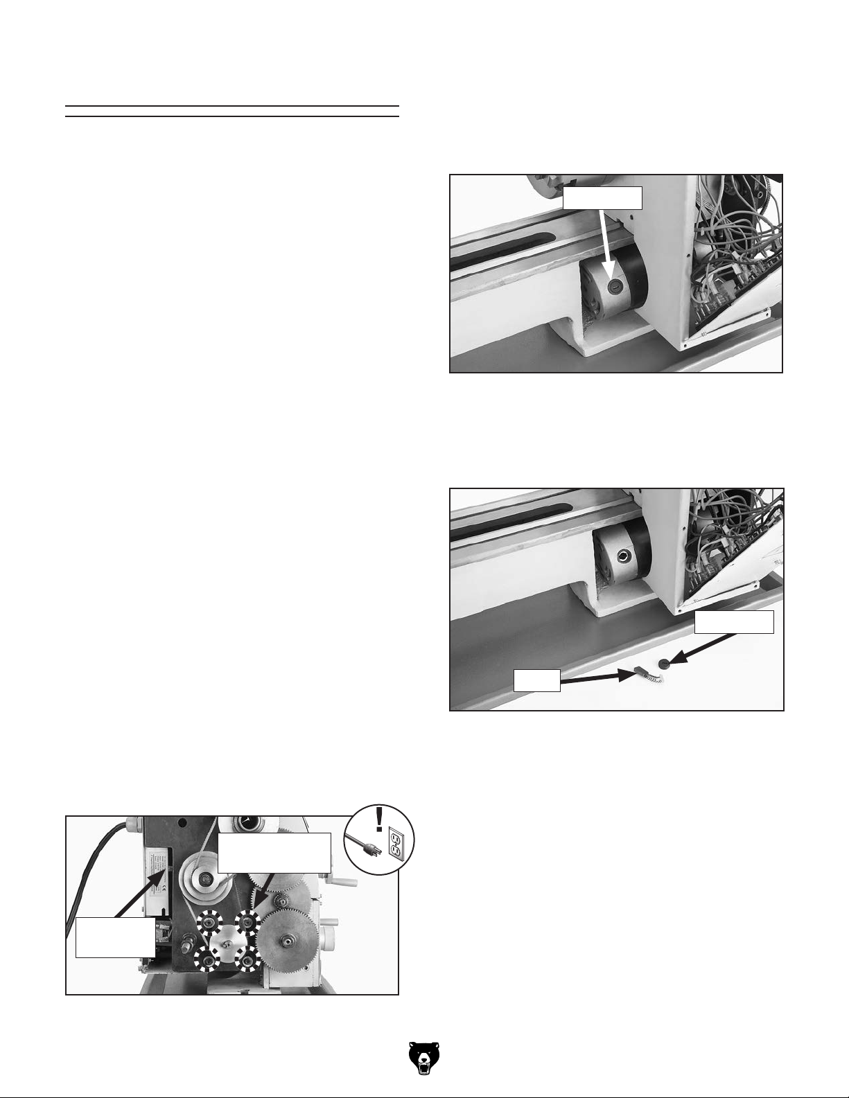
Replacing Brushes
4. Remove motor mount cap screws (see Figure
151).
This machine is equipped with one (G0768) or two
(G0769) universal motors that use carbon brushes
to transmit electrical current inside the motor. These
brushes are considered to be regular "wear items" or
"consumables" that will eventually need to be
replaced. The frequency of this replacement is
directly related to how much the motor is used
and how hard it is pushed.
Replace the carbon brushes when the motor no longer reaches full power, or when the brushes measure less than
Tools Needed Qty
Hex Wrench 3, 4mm .....................................1 Ea
Flat Head Screwdriver #2 .................................. 1
Phillips Head Screwdriver #2 ............................ 1
G0768/G0769 Lathe Motor Replacement Brushes:
P0768046
G0769 Mill Motor Replacement Brushes:
P0769786
1
⁄4" long (new brushes are 5⁄8" long).
5. Rotate motor to access top motor brush
shown in Figure 152.
Brush Cap
Figure 152. Location of top motor brush cap
(Model G0768 shown).
6. Unscrew brush cap and carefully remove
brush from motor (see Figure 153).
Replacing Lathe Motor Brushes
1. DISCONNECT MACHINE FROM POWER!
2. Remove end cover, electrical panel, and
back splash to access motor brushes.
Note: Carefully handle the electrical panel.
Try to avoid straining any wires so they do
not disconnect. On Model G0769 remove mill
motor cable harness and cable clamp from
back splash before removing it.
3. Loosen tensioner screw several turns (see
Figure 151) to remove tension on V-belts.
Motor Mount
Cap Screws
Tensioner
Screw
Brush Cap
Brush
Figure 153. Top motor brush components
removed (Model G0768 shown).
7. Install new brush and re-install brush cap.
8. Repeat Steps 5–7 to replace bottom motor
brush.
9. Re-install motor with screws removed earlier.
10. Tension V-belts (refer to Tensioning V-Belts
on Page 81 for details).
11. Re-install back splash, electrical panel, and
end cover.
-86-
Figure 151. Motor mounting screws
(Model G0768 shown).
12. G0769 Only: Re-install cable harness onto
back splash with cable clamp.
Model G0768/G0769 (Mfd. Since 6/17)
Page 93
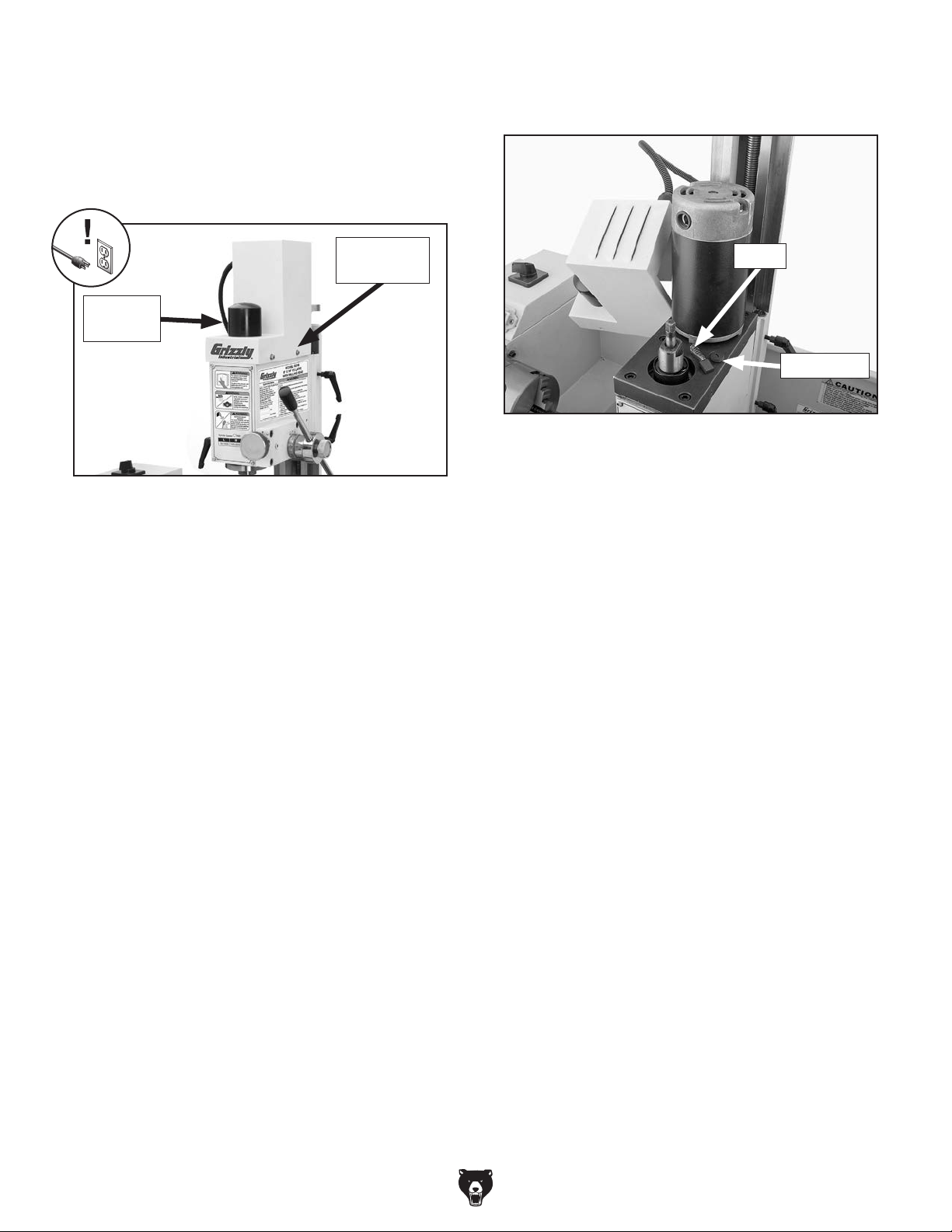
Replacing Mill Motor Brushes (G0769)
1. DISCONNECT MACHINE FROM POWER!
2. Remove drawbar cap, then remove motor
cover by removing cap screws (see Figure
154).
3. Unscrew front brush cap and carefully remove
brush from motor (see Figure 155).
Cap Screw
(1 of 4)
Drawbar
Cap
Figure 154. Location of mill motor cover screws.
Brush
Brush Cap
Figure 155. Front motor brush components
removed.
4. Install new brush and re-install brush cap.
5. Repeat Steps 3–4 to replace rear motor
brush.
6. Replace mill motor cover and drawbar cap.
Model G0768/G0769 (Mfd. Since 6/17)
-87-
Page 94

These pages are current at the time of printing. However, in the spirit of improvement, we may make changes to the electrical systems of future machines. Compare the manufacture date of your machine to the one
number and manufacture date of your
machine before calling. This information can be found on the main machine label.
SECTION 9: WIRING
stated in this manual, and study this section carefully.
If there are differences between your machine and what is shown in this section, call Technical Support at
(570) 546-9663 for assistance BEFORE making any changes to the wiring on your machine. An updated
wiring diagram may be available. Note: Please gather the serial
Wiring Safety Instructions
SHOCK HAZARD. Working on wiring that is con-
nected to a power source is extremely dangerous.
Touching electrified parts will result in personal
injury including but not limited to severe burns,
electrocution, or death. Disconnect the power
from the machine before servicing electrical components!
MODIFICATIONS. Modifying the wiring beyond
what is shown in the diagram may lead to unpredictable results, including serious injury or fire.
This includes the installation of unapproved aftermarket parts.
WIRE CONNECTIONS. All connections must
be tight to prevent wires from loosening during
machine operation. Double-check all wires disconnected or connected during any wiring task to
ensure tight connections.
CIRCUIT REQUIREMENTS. You MUST follow
the requirements at the beginning of this manual
when connecting your machine to a power source.
WIRE/COMPONENT DAMAGE. Damaged wires
or components increase the risk of serious personal injury, fire, or machine damage. If you notice
that any wires or components are damaged while
performing a wiring task, replace those wires or
components.
MOTOR WIRING. The motor wiring shown in
these diagrams is current at the time of printing
but may not match your machine. If you find this
to be the case, use the wiring diagram inside the
motor junction box.
CAPACITORS/INVERTERS. Some capacitors
and power inverters store an electrical charge for
up to 10 minutes after being disconnected from
the power source. To reduce the risk of being
shocked, wait at least this long before working on
capacitors.
EXPERIENCING DIFFICULTIES. If you are experiencing difficulties understanding the information
included in this section, contact our Technical
Support at (570) 546-9663.
The photos and diagrams
included in this section are
best viewed in color. You
can view these pages in
color at www.grizzly.com.
-88-
Model G0768/G0769 (Mfd. Since 6/17)
Page 95

G0768 Wiring Overview
Direction Switch
Fuses
and
Plug
JD-014
REV 091111
Circuit
Board
DC Motor
Speed Control
JYMC-220B-II
Emergency Stop
DRO
RPM Sensor
(Inside)
Potentiometer
JD-013
REV C 120823
Circuit Board
Motor (Inside)
110V 10A
Single-Phase
3
⁄4 HP 5250 RPM
Model G0768/G0769 (Mfd. Since 6/17)
-89-
Page 96

Switch
Direction
EN61058
Left Side
KEDU ZHA
159
2
10 6
DIRECTION SWITCH
232413
A1
KEDU
14
120V
KJD17B
EN61058
Right Side
KEDU ZHA
3
7
8 412
11
DIRECTION SWITCH
G0768 Wiring
SN121105
DRO
ZD-HAWK
RPM Sensor
J1
1k7±5
WX14-12
Potentiometer
3/4 HP
Motor
110V 10A
Single Phase
Front Panel
(Viewed From Backside)
Compartment
Inside Electrical
5250RPM
Top Panel
(Viewed From Backside)
Stop
Emergency
Hot
Neutral
110 VAC
GND
GND
Ground
5-15 Plug
(As Recommended)
A
IN/L
IN/L
IN/N
IN/E
B
P3
IN/L
To Plug
A
Fuse
IN/N
F15al250V
L2
F
P1
P2
JD-014 REV A 091111
F+
L1
GND
A+
IN/N
GND
A
JD-013 REV C 120823
DC Motor Speed Control JYMC_220B-II
Fuse
F10al250V
OUT/N
OUT/N
OUT/E
OUT/L
OUT/L
J
J
Rear Panel
(Viewed from Backside)
-90-
Model G0768/G0769 (Mfd. Since 6/17)
Page 97

G0768 Wiring Photos
Figure 158. RPM sensor.
Figure 156. Front panel.
Figure 157. Top panel.
Figure 159. Back panel.
Model G0768/G0769 (Mfd. Since 6/17)
-91-
Page 98

Mill Motor
(Inside)
110V 10A
Single-Phase
3
⁄4 HP 4800 RPM
Lathe/Mill Selector Switch
G0769 Wiring Overview
Fuses and
Plug
Speed
Control
Circuit Board
Filter
Circuit Board
Direction
Switch
Emergency Stop
DRO
RPM Sensor
(Inside)
Potentiometer
Lathe Motor
(Inside)
110V 10A
Single-Phase
3
⁄4 HP 5250 RPM
-92-
Model G0768/G0769 (Mfd. Since 6/17)
Page 99

G0769 Wiring
Top Panel
EN61058
Left Side
KEDU ZHA
Switch
Direction
15
26
9
10
DIRECTION SWITCH
232413
A1
Emergency Stop
Ith10A
Ui AC-11
440V 360VA
14
KEDU
LW8-10/6
SELECTION
120V
KJD17B
31
SWITCH
EN61058
Right Side
KEDU ZHA
3
7
8 4
11
12
DIRECTION SWITCH
75
119
SN130722
DRO
Sensor
Lathe RPM
J1
1k7±5
WX14-12
Front Panel
Potentiometer
Inside Electrical
3/4 HP
110V 10A
5250 RPM
Single Phase
Lathe Motor
(Viewed From Backside)
Compartment
GND
2321
13 15
17 19
Lathe/Mill Drill
ZD-HAWK
Mill RPM Sensor
J1
Selection Switch
Ith10A
Ui AC-11
440V 360VA
Motor
110V 10A
Mill/Drill
LW8-10/6
Hot
SWITCH
SELECTION
3/4 HP
4800 RPM
Single Phase
Neutral
110 VAC
24
68
5-15 Plug
10
12
2224
16 14
20 18
Ground
(As Recommended)
To Plug
Fuse
F15al250V
Fuse
F10al250V
Fuse
F10al250V
A+
CIRCUIT BOARD
SPEED CONTROL
P2
P3
P1
1N
1N
N
L
FILTER CIRCUIT BOARD
F
L1
L2
F+
A
L1
G
B
A
J1
N1
Rear Panel
(Viewed from Backside)
Model G0768/G0769 (Mfd. Since 6/17)
-93-
Page 100

G0769 Wiring Photos
Figure 160. Front panel.
Figure 161. Top panel components.
Figure 163. RPM sensor.
Figure 164. Back panel.
-94-
Figure 162. Mill/drill motor.
Model G0768/G0769 (Mfd. Since 6/17)
 Loading...