

Page 1

MODEL G0764
14" SLIDING TABLE SAW
OWNER'S MANUAL
(For models manufactured since 02/14)
COPYRIGHT © MAY, 2014 BY GRIZZLY INDUSTRIAL, INC., REVISED MAY, 2015 (MN)
WARNING: NO PORTION OF THIS MANUAL MAY BE REPRODUCED IN ANY SHAPE
OR FORM WITHOUT THE WRITTEN APPROVAL OF GRIZZLY INDUSTRIAL, INC.
#DMTSBL16205 PRINTED IN TAIWAN
V2 . 0 5.15
Page 2

This manual provides critical safety instructions on the proper setup,
operation, maintenance, and service of this machine/tool. Save this
document, refer to it often, and use it to instruct other operators.
Failure to read, understand and follow the instructions in this manual
may result in fire or serious personal injury—including amputation,
electrocution, or death.
The owner of this machine/tool is solely responsible for its safe use.
This responsibility includes but is not limited to proper installation in
a safe environment, personnel training and usage authorization,
proper inspection and maintenance, manual availability and comprehension, application of safety devices, cutting/sanding/grinding tool
integrity, and the usage of personal protective equipment.
The manufacturer will not be held liable for injury or property damage
from negligence, improper training, machine modifications or misuse.
Some dust created by power sanding, sawing, grinding, drilling, and
other construction activities contains chemicals known to the State
of California to cause cancer, birth defects or other reproductive
harm. Some examples of these chemicals are:
• Lead from lead-based paints.
• Crystalline silica from bricks, cement and other masonry products.
• Arsenic and chromium from chemically-treated lumber.
Your risk from these exposures varies, depending on how often you
do this type of work. To reduce your exposure to these chemicals:
Work in a well ventilated area, and work with approved safety equipment, such as those dust masks that are specially designed to filter
out microscopic particles.
Page 3

Table of Contents
INTRODUCTION ............................................... 3
Machine Description ...................................... 3
Contact Info.................................................... 3
Manual Accuracy ........................................... 3
Identification ................................................... 4
Controls & Components ................................. 5
Rip Fence ....................................................................5
Saw Blades .................................................................5
Front Controls ............................................................. 6
Rear Controls .............................................................. 6
Glossary Of Terms ......................................... 7
Sliding Table Saw Capacities ........................ 8
Machine Data Sheet ...................................... 9
SECTION 1: SAFETY ..................................... 12
Safety Instructions for Machinery ................ 12
Additional Safety for Sliding Table Saws ..... 14
Additional Safety for Sliding Table Saws ..... 14
Preventing Kickback .................................... 15
Protecting Yourself From Kickback.............. 15
SECTION 2: POWER SUPPLY ...................... 16
Availability .................................................................16
Full-Load Current Rating ...........................................16
Circuit Information .....................................................16
Circuit Requirements for 220V ..................................16
Circuit Requirements for 440V ..................................16
Connection Type .......................................................17
Grounding Instructions ..............................................17
Extension Cords ........................................................17
440V Conversion ......................................... 17
SECTION 3: SETUP ....................................... 19
Needed for Setup ......................................... 19
Unpacking .................................................... 19
Hardware Recognition Chart ....................... 20
Inventory ...................................................... 21
Cleanup ........................................................ 23
Site Considerations ...................................... 24
Lifting & Placing Saw ................................... 25
Assembly ..................................................... 26
Dust Collection ............................................. 37
Power Connection........................................ 38
Test Run ...................................................... 39
Recommended Adjustments ........................ 41
SECTION 4: OPERATIONS ........................... 42
Operation Overview ..................................... 42
Workpiece Inspection................................... 43
Through & .................................................... 43
Non-Through Cuts ...................................... 43
Through Cuts ............................................................43
Non-Through Cuts .....................................................43
Blade Guard ................................................. 44
Understanding Blade Guard ......................................44
Adjusting Blade Guard ..............................................44
When to Use Blade Guard ........................................44
Side Covers ...............................................................44
Riving Knife .................................................. 45
Riving Knife Installation & Removal ..........................45
Blade Requirements .................................... 46
Blade Selection ............................................ 46
Changing Speed .......................................... 48
Changing Main Blade .................................. 49
Replacing & Aligning Scoring Blade ............ 50
Replacing Scoring Blade ...........................................51
Aligning Scoring Blade ..............................................52
Setting Up Crosscut Fence .......................... 53
Positioning Crosscut Fence ......................................53
Adjusting Crosscut Fence Distance from Blade .......54
Positioning Crosscut Table Along Sliding Table .......55
Rip Cutting ................................................... 56
Rip Cutting with Sliding Table ...................................56
Rip Cutting with Rip Fence .......................................57
Crosscutting ................................................. 58
Crosscutting Full-Size Panels ...................................59
Crosscutting Smaller Panels .....................................59
Crosscutting Using Rip Fence as Cut-Off Gauge ....59
Miter Cutting................................................. 60
Dado Cutting ................................................ 61
Rabbet Cutting ............................................. 62
Resawing ..................................................... 63
Making a Resaw Barrier ............................................63
Resawing Operations ................................................64
Narrow-Rip Auxiliary Fence & Push Block .. 65
Making a Narrow-Rip Push Block for an Auxiliary
Fence ........................................................................
Using the Auxiliary Fence and Push Block ...............66
65
SECTION 5: AFTERMARKET
ACCESSORIES FROM GRIZZLY .................. 67
Page 4

SECTION 6: MAINTENANCE ......................... 70
Schedule ...................................................... 70
Cleaning & Protecting .................................. 70
Lubrication ................................................... 71
Slide Shafts ...............................................................71
Elevation Worm Gears ..............................................72
Elevation Leadscrew .................................................72
Tilt Leadscrew ...........................................................72
SECTION 7: SERVICE ................................... 73
Troubleshooting ........................................... 73
Belt Service .................................................. 75
Tensioning Scoring Motor Belt ..................................75
Replacing Scoring Motor Belt ...................................75
Tensioning Main Motor Belts ....................................75
Replacing Main Motor Belts .....................................76
Blade Tilt Calibration .................................... 77
0° Stop ......................................................................77
45° Stop ....................................................................77
Tilt Scale Calibration .................................................77
Sliding Table Parallel Adjustment ................ 78
Sliding Table Movement Adjustment ........... 79
Squaring Crosscut Fence to Blade .............. 79
Riving Knife Mounting Block ........................ 81
Calibrating Rip Fence .................................. 82
Height Above Table ...................................................82
Parallelism To Blade .................................................82
Calibrating Rip Fence Scale .....................................82
SECTION 8: WIRING ...................................... 83
Wiring Safety Instructions ............................ 83
Wiring Overview ........................................... 84
Component Location Index .......................... 85
Control Panel Wiring .................................... 86
220V Electrical Panel Wiring ....................... 87
440V Electrical Panel Wiring ....................... 88
Scoring Motor Wiring ................................. 90
Main Motor Wiring ....................................... 91
Master Power Switch Wiring ....................... 92
SECTION 9: PARTS ....................................... 93
Body ............................................................. 93
Main Tables ................................................. 95
Control Panel ............................................... 96
Blade Enclosure ........................................... 97
Main Motor ................................................... 98
Main Blade Arbor ......................................... 99
Blade Tilt System ....................................... 100
Blade Elevation System ............................. 101
Scoring Blade Arbor ................................... 103
Scoring Blade Adjustment System ............ 104
Scoring Blade Motor .................................. 105
Crosscut Table Swing Arm ........................ 106
Crosscut Table ........................................... 107
Crosscut Fence .......................................... 109
Rip Fence................................................... 110
Sliding Table .............................................. 112
Blade Guard Assembly .............................. 113
Sliding Table Accessories .......................... 115
Electrical Box Components ........................ 116
Labels & Cosmetics ................................... 117
WARRANTY & RETURNS ........................... 121
Page 5
INTRODUCTION
We are proud to provide a high-quality owner’s
manual with your new machine!
We
instructions, specifications, drawings, and photographs
in this manual. Sometimes we make mistakes, but
our policy of continuous improvement also means
that
you receive is
slightly different than shown in the manual
If you find this to be the case, and the difference
between the manual and machine leaves you
confused or unsure about something
check our
website for an updated version. W
current
manuals and
on our web-
site at
Alternatively, you can call our Technical Support
for help. Before calling, make sure you write down
the
from
the machine ID label (see below). This information
is required for us to provide proper tech support,
and it helps us determine if updated documentation is available for your machine.
We stand behind our machines! If you have questions or need help, contact us with the information
below. Before contacting, make sure you get the
serial number
machine ID label. This will help us help you faster.
We want your feedback on this manual. What did
you like about it? Where could it be improved?
Please take a few minutes to give us feedback.
Machine Description
A sliding table saw is primarily used to rip and
crosscut sheet stock or panels in a production
setting. The sliding table saves time and increases
accuracy by removing the burden of sliding large
and heavy panels over a stationary table surface.
This saw can also be used as a traditional table
saw for most types of through-cuts.
The Model G0764 is equipped with a scoring
blade, which is a smaller circular saw blade
located in front of the main blade. It makes a shallow cut in the workpiece in the opposite direction
of the main blade, greatly reducing tear-out and
chipped edges.
When using the sliding table saw as a traditional
table saw, the sliding table is locked in place and
the rip fence is then used to guide the workpiece
through the cut.
Contact Info
Email: techsupport@grizzly.com
and manufacture date from the
Grizzly Technical Support
1203 Lycoming Mall Circle
Muncy, PA 17756
Phone: (570) 546-9663
Manual Accuracy
made every effort to be exact with the
sometimes the machine
.
,
e post
manual updates for free
www.grizzly.com.
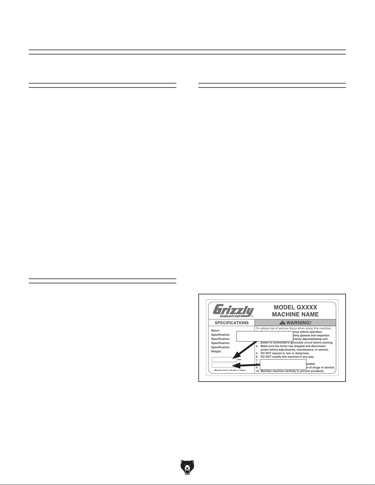
Manufacture Date and Serial Number
Manufacture Date
Serial Number
Model G0764 (Mfd. Since 02/14)
Grizzly Documentation Manager
P.O. Box 2069
Bellingham, WA 98227-2069
Email: manuals@grizzly.com
-3-
Page 6
Identification
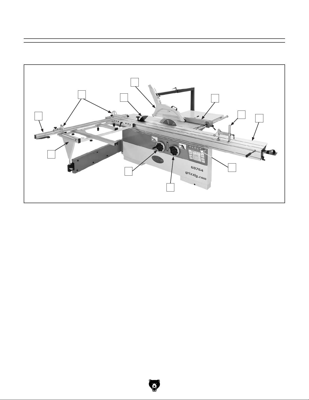
Become familiar with the names and locations of the controls and features shown below to better understand
the instructions in this manual.
E
C
B
A
A. Crosscut Table. Provides a wide, stable
platform for supporting full-size panels during
crosscutting operations. This is where you
put panels when you are going to cut them
using the sliding table.
B. Crosscut Fence. Used during crosscutting
operations to keep panels at the desired
angle to the blade. Features a scale and flipstyle stop blocks.
C. Flip Stops. Used for quick, precise measure-
ments for repeatable cuts when using crosscutting fence.
D. Edge Shoe. Used with hold-down, keeps
the other end of workpiece secured to sliding
table.
E. Blade Guard. Fully-enclosed, adjustable
blade guard maintains maximum protection
around the saw blade with a 2
that effectively extracts dust from the cutting
operation.
D
K
1
⁄2" dust port
F
G
I
J
F. Rip Fence. Fully-adjustable with micro-
adjustment knob for precision cuts of smaller
workpieces. Fence face can be positioned for
standard cutting operations, or in the lower
position for blade guard clearance during narrow ripping operations.
G. Hold-Down. Quickly clamps one end of
workpiece to sliding table.
H. Sliding Table. Ball-bearing rollers make it
quicker and easier to guide large, heavy panels through the cut.
I. Control Panel. Features push-button con-
trols for operating saw.
J. Blade Angle Handwheel. Adjusts angle of
main and scoring blades for beveled cuts.
K. Blade Elevation Handwheel. Adjusts height
of the main saw blade.
H
-4-
Model G0764 (Mfd. Since 02/14)
Page 7
Controls &
To reduce your risk of
serious injury, read this
entire manual BEFORE
Components
using machine.
P. Rip Fence Lock Handle. Secures the rip
fence assembly into position along the fence
rail so that the workpiece is stable when cutting.
Q. Micro-Adjust Lock Knob. Enables the use
of the micro-adjust knob for precise positioning of the rip fence.
Saw Blades
Refer to Figures 1–4 and the following descriptions to become familiar with the basic controls
and components of this machine. Understanding
these items and how they work will help you
understand the rest of the manual and stay safe
when operating this saw.
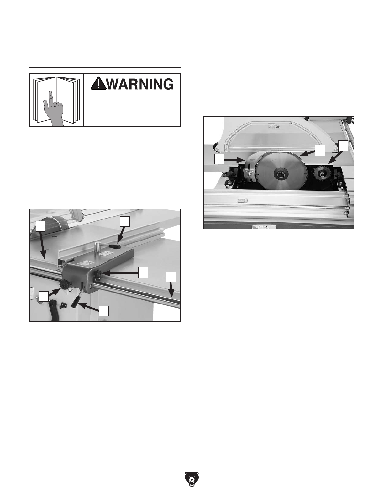
Rip Fence
L
Q
P
Figure 1. Rip fence controls.
L. Rip Fence Scale. Helps you measure the cut
when rip cutting.
M
N
O
S
R
Figure 2. Saw blades.
R. Riving Knife. Maintains kerf opening during
cutting operations. This function is crucial to
preventing kickback caused by the kerf closing behind the blade.
S. Main Blade. Performs the cutting operation.
T. Scoring Blade. Rotates in the opposite
direction of the main blade and pre-cuts the
surface of the workpiece before the actual
cutting operation is performed to reduce
tearout or chipping. The scoring blade is
adjustable for kerf thickness and alignment
with the main blade.
T
M. Slide Lock Handle. Secures the aluminum
fence face on its forward/backward slide
track to support the workpiece.
N. Micro-Adjust Knob. Provide precise adjust-
ments of the fence along the rail. Tighten
micro-adjust lock knob to use this feature.
O. Rip Fence Rail. Provides a stable side-to-
side path for sliding the rip fence assembly
toward or away from blade.
Model G0764 (Mfd. Since 02/14)
-5-
Page 8
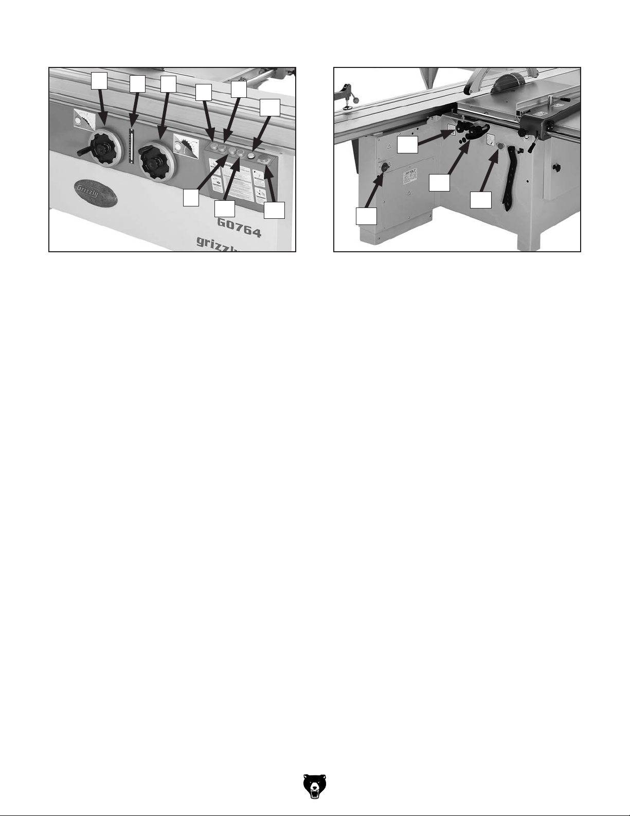
Front Controls Rear Controls
U
U. Main Blade Elevation Handwheel. Raises
and lowers the main blade. The lock knob in
the center secures the handwheel to prevent
blade from moving during operation.
V. Tilt Scale. Displays the tilt angle of blades in
degrees.
W. Blade Tilt Handwheel. Adjusts the tilt angle
of both blades. The lock knob in the center
secures the handwheel to prevent blade from
moving during operation.
X. Main Blade ON Button.
V
W
Figure 3. Front controls.
X
Z
AA
Y
AB
AC
AE
AF
AG
AD
Figure 4. Rear controls.
AD. Master Power Switch. Enables power flow
to the machine.
AE. Scoring Blade Elevation Knob. Raises
and lowers the scoring blade to change the
kerf thickness. The knurled wheel behind the
knob secures the setting to prevent blade
from moving during operation.
AF. Scoring Blade Alignment Knob. Adjusts
the alignment of scoring blade to the main
blade. The knurled wheel behind the knob
secures the setting to prevent blade from
moving during operation.
Y. Main Blade OFF Button.
Z. Scoring Blade ON Button.
AA. Scoring Blade OFF Button.
AB. Power Lamp. When lit, provides a visual
indicator that power is enabled to the saw.
AC. Emergency Stop Button. Turns both motors
OFF. Twist clockwise until it pops out to reset.
-6-
AG. Emergency Stop Button. Turns both motors
OFF. Twist clockwise until it pops out to reset.
Model G0764 (Mfd. Since 02/14)
Page 9

Glossary Of Terms
The following is a list of common definitions, terms and phrases used throughout this manual as they relate
to this sliding table saw and woodworking in general. Become familiar with these terms for assembling,
adjusting or operating this machine. Your safety is VERY important to us at Grizzly!
Arbor: Metal shaft extending from the drive
mechanism, to which saw blade is mounted.
Bevel Edge Cut: Tilting the arbor and saw blade
to an angle between 0° and 45° to cut a beveled edge onto a workpiece.
Blade Guard: Metal or plastic safety device that
mounts over the saw blade. Its function is to
prevent the operator from coming into contact
with the saw blade.
Crosscut: Cutting operation in which the cross-
cut fence is used to cut across the grain, or
across the shortest width of the workpiece.
Dado Blade: Blade or set of blades that are used
to cut grooves and rabbets.
Dado Cut: Cutting operation that cuts a flat bot-
tomed groove into the face of the workpiece.
Featherboard: Safety device used to keep the
workpiece against the rip fence and against the
table surface.
Kerf: The resulting cut or gap in the workpiece
from the saw blade passing through it while
cutting.
Kickback: A dangerous event that happens if
the blade catches on the workpieces while
cutting. The force of the blade then throws the
workpiece back toward the operator with what
sounds like a horrible explosion. The danger
comes from flying stock striking the operator or
bystanders. The operator’s hands may also be
pulled into the blade during the kickback. Refer
to Preventing Kickback on Page 15 for additional information.
Parallel: When two objects are spaced an equal
distance apart at every point along two given
lines or planes (I.e. the rip fence face is parallel
to the face of the saw blade).
Non-Through Cut: A sawing operation in which
the workpiece is not completely sawn through.
Dado and rabbet cuts are considered NonThrough Cuts because the blade does not
protrude above the top face of the wood stock.
Perpendicular: Lines or planes that intersect
and form right angles. I.e. the blade is perpendicular to the table surface.
Push Stick: Safety device used to push the
workpiece through a cutting operation. Used
most often when rip cutting thin workpieces.
Rabbet: Cutting operation that creates an
L-shaped channel along the edge of the
workpiece.
Riving Knife: Metal plate located behind the
blade maintains the kerf opening in the wood
when cutting, and helps reduce the risk of
injury from a kickback that otherwise would
result in amputation.
Straightedge: A tool with a perfectly straight
edge used to check the flatness, parallelism,
or consistency of a surface(s).
Through Cut: A sawing operation in which the
workpiece is completely sawn through.
Rip Cut: Cutting operation in which the rip fence
is used to cut with the grain, or cut across the
widest width of the workpiece.
Model G0764 (Mfd. Since 02/14)
-7-
Page 10
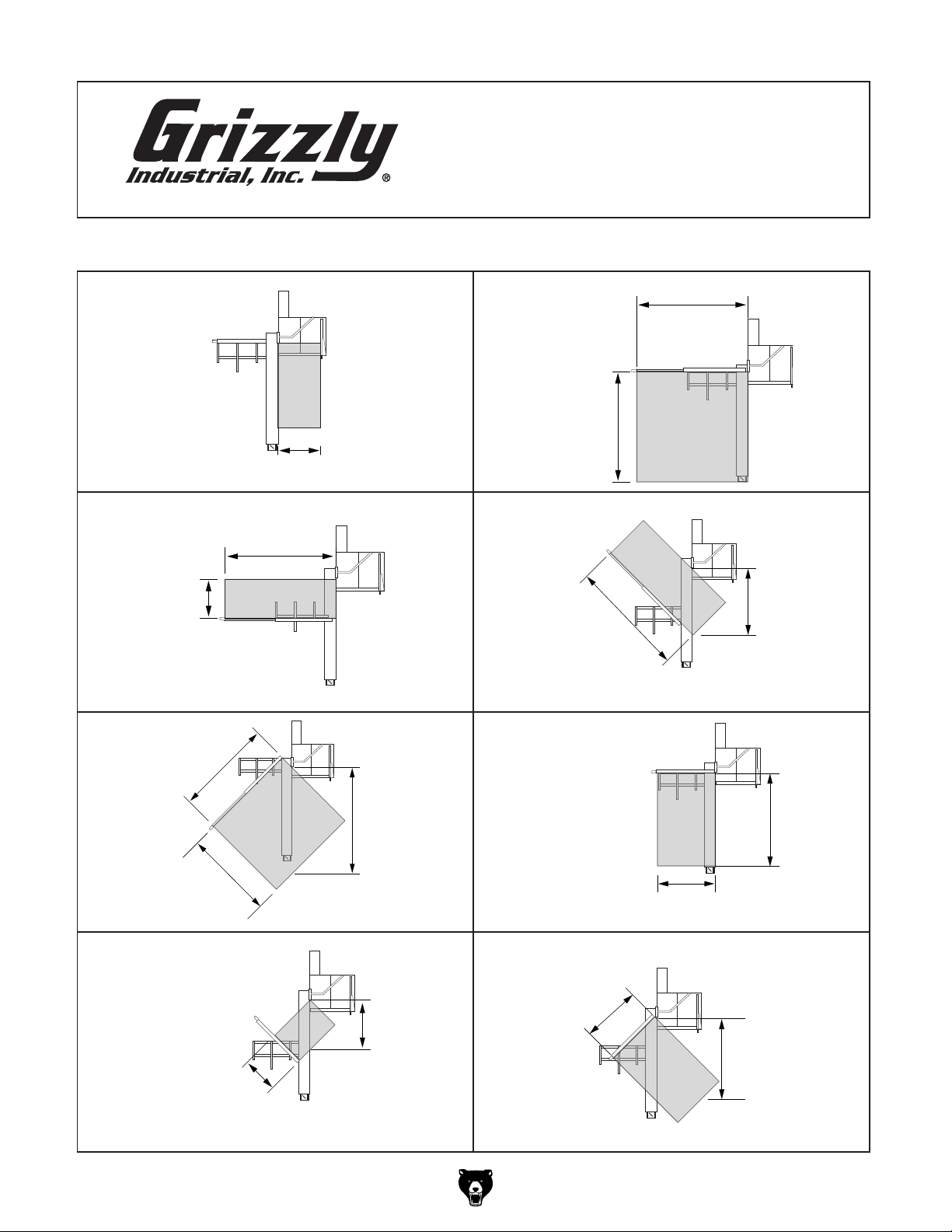
SLIDING TABLE
SAW CAPACITIES
Customer Service #: (570) 546-9663 • To Order Call: (800) 523-4777 • Fax #: (800) 438-5901
MODEL G0764 14" SLIDING TABLE SAW
134"
124"
Ripping Width
42"
Miter Cut 90º
(push cut)
Miter Cut 45º
134"
90"
511/4"
134"
126"
Cross Cut
134"
Miter Cut 45º
(push cut)
Cross Cut
(fence not extended)
58"
124"
731/4"
731/4"
Miter Cut 45º
(push cut, fence not extended)
-8-
731/4"
58"
126"
Miter Cut 45º
(fence not extended)
Model G0764 (Mfd. Since 02/14)
Page 11

MACHINE DATA
SHEET
Customer Service #: (570) 546-9663 · To Order Call: (800) 523-4777 · Fax #: (800) 438-5901
MODEL G0764 14" SLIDING TABLE SAW
Product Dimensions:
Weight............................................................................................................................................................ 1575 lbs.
Width (side-to-side) x Depth (front-to-back) x Height....................................................................... 133 x 202 x 65 in.
Footprint (Length x Width)............................................................................................................... 74-1/2 x 35-1/2 in.
Space Required for Full Range of Movement (Width x Depth)................................................................ 279 x 203 in.
Shipping Dimensions:
Carton #1
Type......................................................................................................................................... Wood Slat Crate
Content................................................................................................................................................. Machine
Weight.................................................................................................................................................. 1600 lbs.
Length x Width x Height............................................................................................................. 83 x 45 x 44 in.
Must Ship Upright......................................................................................................................................... Yes
Carton #2
Type......................................................................................................................................... Wood Slat Crate
Content.......................................................................................................................................... Sliding Table
Weight.................................................................................................................................................... 215 lbs.
Length x Width x Height............................................................................................................. 130 x 17 x 9 in.
Must Ship Upright......................................................................................................................................... Yes
Electrical:
Power Requirement..................................................................................................... 220V or 440V, 3-Phase, 60 Hz
Prewired Voltage.................................................................................................................................................. 220V
Full-Load Current Rating............................................................................................... 29.2A at 220V, 14.6A at 440V
Minimum Circuit Size.......................................................................................................... 40A at 220V, 20A at 440V
Connection Type....................................................................................................................... Permanent (Hardwire)
Switch Type............................................................................................. Magnetic with Thermal Overload Protection
Voltage Conversion Kit............................................................................................................. G440VG0764 for 440V
Recommended Phase Converter....................................................................................................................... G7978
Motors:
Main
Type........................................................................................................................................... TEFC Induction
Horsepower.............................................................................................................................................. 10 HP
Phase.................................................................................................................................................... 3-Phase
Amps......................................................................................................................... 26A at 220V, 13A at 440V
Speed................................................................................................................................................ 3450 RPM
Power Transfer .................................................................................................................................. Belt Drive
Bearings.................................................................................................... Sealed and Permanently Lubricated
Scoring Blade
Type........................................................................................................................................... TEFC Induction
Horsepower................................................................................................................................................ 1 HP
Phase.................................................................................................................................................... 3-Phase
Amps....................................................................................................................... 3.2A at 220V, 1.6A at 440V
Speed................................................................................................................................................ 3450 RPM
Power Transfer .................................................................................................................................. Belt Drive
Bearings.................................................................................................... Sealed and Permanently Lubricated
Model G0764 (Mfd. Since 02/14)
-9-
Page 12

Main Specifications:
Operation Information
Main Blade Size......................................................................................................................................... 14 in.
Main Blade Arbor Size................................................................................................................................. 1 in.
Scoring Blade Size................................................................................................................................ 4-3/4 in.
Scoring Blade Arbor Size........................................................................................................................ 20 mm
Main Blade Tilt.................................................................................................................................. 0 – 45 deg.
Main Blade Speed......................................................................................................... 3000, 4000, 5000 RPM
Scoring Blade Tilt............................................................................................................................. 0 – 45 deg.
Scoring Blade Speed......................................................................................................................... 8000 RPM
Cutting Capacities
Max Depth of Cut At 90 Deg.................................................................................................................. 4-1/8 in.
Max Depth of Cut At 45 Deg.................................................................................................................. 2-7/8 in.
Rip Fence Max Cut Width.................................................................................................................... 51-1/4 in.
Sliding Table w/Crosscut Fence Max Cut Width...................................................................................... 134 in.
Sliding Table w/Crosscut Fence Max Cut Length.................................................................................... 124 in.
Miter Fence Max Cut Width at 45 Deg..................................................................................................... 126 in.
Table Information
Floor To Table Height.......................................................................................................................... 34-1/2 in.
Table Size Length................................................................................................................................ 39-1/2 in.
Table Size Width................................................................................................................................. 21-1/2 in.
Table Size Thickness.......................................................................................................................... 2-5/16 in.
Table Size With Ext Wings Length...................................................................................................... 35-1/4 in.
Table Size With Ext Wings Width........................................................................................................ 59-1/8 in.
Table Size With Ext Wings Thickness................................................................................................... 2-1/2 in.
Sliding Table Length................................................................................................................................ 126 in.
Sliding Table Width.................................................................................................................................... 14 in.
Sliding Table Thickness......................................................................................................................... 6-3/4 in.
Sliding Table T-Slot Top Width................................................................................................................. 5/8 in.
Sliding Table T-Slot Height....................................................................................................................... 5/8 in.
Sliding Table T-Slot Bottom Width......................................................................................................... 1-1/2 in.
Fence Information
Crosscut Fence Type.......................................................................................................... Extruded Aluminum
Crosscut Fence Size Length...................................................................................................................... 73 in.
Crosscut Fence Size Width................................................................................................................... 2-3/8 in.
Crosscut Fence Size Height.................................................................................................................. 2-3/8 in.
Crosscut Fence Number of Stops.................................................................................................................... 2
Rip Fence Type................................................................................................................. Single Lever Locking
Rip Fence Size Length........................................................................................................................ 39-3/8 in.
Rip Fence Size Width.................................................................................................................................. 2 in.
Rip Fence Size Height........................................................................................................................... 3-1/2 in.
Construction Materials
Table.................................................................................................................................................... Cast Iron
Cabinet....................................................................................................................................................... Steel
Rip Fence Rails.......................................................................................................................... Chromed Steel
Guard............................................................................................................................ Sheet Steel and Plastic
Spindle Bearing Type.................................................................................... Sealed & Permanently Lubricated
Cabinet Paint Type/Finish.......................................................................................................... Powder Coated
Other Related Information
No of Dust Ports............................................................................................................................................... 2
Dust Port Size.................................................................................................................................... 2-1/2, 5 in.
-10 -
Model G0764 (Mfd. Since 02/14)
Page 13

Other Specifications:
Country of Origin .............................................................................................................................................. Taiwan
Warranty ........................................................................................................................................................... 1 Year
Approximate Assembly & Setup Time ............................................................................................................. 3 Hours
Serial Number Location .................................................................................................. ID Label on Side of Machine
ISO 9001 Factory .................................................................................................................................................. Yes
CSA, ETL, or UL Certified/Listed ............................................................................................................................ No
Features:
Micro-adjustable rip fence
Scoring saw blade ensures tear-out free cutting
Sliding table on steel ball guide system with heat treated steel ways
Alloy crosscut fence for miter cutting 45 deg. right and left
Miter fence has two swing stops for repetitive cutting
Adjustable riving knife
Overhead blade guard
Safety limit switch for blade cover
Model G0764 (Mfd. Since 02/14)
-11-
Page 14
SECTION 1: SAFETY
For Your Own Safety, Read Instruction
Manual Before Operating This Machine
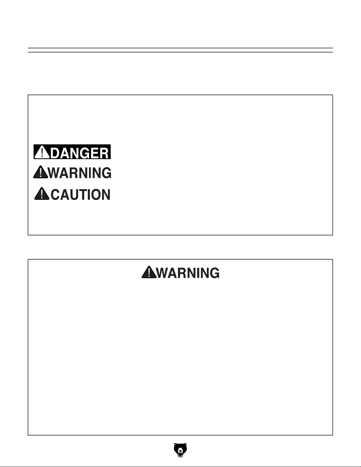
The purpose of safety symbols is to attract your attention to possible hazardous conditions.
This manual uses a series of symbols and signal words intended to convey the level of importance of the safety messages. The progression of symbols is described below. Remember that
safety messages by themselves do not eliminate danger and are not a substitute for proper
accident prevention measures. Always use common sense and good judgment.
Indicates an imminently hazardous situation which, if not avoided,
WILL result in death or serious injury.
Indicates a potentially hazardous situation which, if not avoided,
COULD result in death or serious injury.
Indicates a potentially hazardous situation which, if not avoided,
MAY result in minor or moderate injury. It may also be used to alert
against unsafe practices.
This symbol is used to alert the user to useful information about
NOTICE
proper operation of the machine.
Safety Instructions for Machinery
OWNER’S MANUAL. Read and understand this
owner’s manual BEFORE using machine.
TRAINED OPERATORS ONLY. Untrained operators have a higher risk of being hurt or killed.
Only allow trained/supervised people to use this
machine. When machine is not being used, disconnect power, remove switch keys, or lock-out
machine to prevent unauthorized use—especially
around children. Make workshop kid proof!
DANGEROUS ENVIRONMENTS. Do not use
machinery in areas that are wet, cluttered, or have
poor lighting. Operating machinery in these areas
greatly increases the risk of accidents and injury.
MENTAL ALERTNESS REQUIRED. Full mental
alertness is required for safe operation of machinery. Never operate under the influence of drugs or
alcohol, when tired, or when distracted.
ELECTRICAL EQUIPMENT INJURY RISKS. You
can be shocked, burned, or killed by touching live
electrical components or improperly grounded
machinery. To reduce this risk, only allow qualified
service personnel to do electrical installation or
repair work, and always disconnect power before
accessing or exposing electrical equipment.
DISCONNECT POWER FIRST.
nect machine from power supply BEFORE making
adjustments, changing tooling, or servicing machine.
This prevents an injury risk from unintended startup
or contact with live electrical components.
EYE PROTECTION. Always wear ANSI-approved
safety glasses or a face shield when operating or
observing machinery to reduce the risk of eye
injury or blindness from flying particles. Everyday
eyeglasses are NOT approved safety glasses.
Always discon-
-12-
Model G0764 (Mfd. Since 02/14)
Page 15

WEARING PROPER APPAREL. Do not wear
clothing, apparel or jewelry that can become
entangled in moving parts. Always tie back or
cover long hair. Wear non-slip footwear to reduce
risk of slipping and losing control or accidentally
contacting cutting tool or moving parts.
HAZARDOUS DUST. Dust created by machinery
operations may cause cancer, birth defects, or
long-term respiratory damage. Be aware of dust
hazards associated with each workpiece material. Always wear a NIOSH-approved respirator to
reduce your risk.
HEARING PROTECTION. Always wear hearing protection when operating or observing loud
machinery. Extended exposure to this noise
without hearing protection can cause permanent
hearing loss.
REMOVE ADJUSTING TOOLS. Tools left on
machinery can become dangerous projectiles
upon startup. Never leave chuck keys, wrenches,
or any other tools on machine. Always verify
removal before starting!
USE CORRECT TOOL FOR THE JOB. Only use
this tool for its intended purpose—do not force
it or an attachment to do a job for which it was
not designed. Never make unapproved modifications—modifying tool or using it differently than
intended may result in malfunction or mechanical
failure that can lead to personal injury or death!
AWKWARD POSITIONS. Keep proper footing
and balance at all times when operating machine.
Do not overreach! Avoid awkward hand positions
that make workpiece control difficult or increase
the risk of accidental injury.
CHILDREN & BYSTANDERS. Keep children and
bystanders at a safe distance from the work area.
Stop using machine if they become a distraction.
GUARDS & COVERS. Guards and covers reduce
accidental contact with moving parts or flying
debris. Make sure they are properly installed,
undamaged, and working correctly BEFORE
operating machine.
FORCING MACHINERY. Do not force machine.
It will do the job safer and better at the rate for
which it was designed.
NEVER STAND ON MACHINE. Serious injury
may occur if machine is tipped or if the cutting
tool is unintentionally contacted.
STABLE MACHINE. Unexpected movement during operation greatly increases risk of injury or
loss of control. Before starting, verify machine is
stable and mobile base (if used) is locked.
USE RECOMMENDED ACCESSORIES. Consult
this owner’s manual or the manufacturer for recommended accessories. Using improper accessories will increase the risk of serious injury.
UNATTENDED OPERATION. To reduce the
risk of accidental injury, turn machine OFF and
ensure all moving parts completely stop before
walking away. Never leave machine running
while unattended.
MAINTAIN WITH CARE. Follow all maintenance
instructions and lubrication schedules to keep
machine in good working condition. A machine
that is improperly maintained could malfunction,
leading to serious personal injury or death.
DAMAGED PARTS. Regularly inspect machine
for damaged, loose, or mis-adjusted parts—or
any condition that could affect safe operation.
Immediately repair/replace BEFORE operating
machine. For your own safety, DO NOT operate
machine with damaged parts!
MAINTAIN POWER CORDS. When disconnecting cord-connected machines from power, grab
and pull the plug—NOT the cord. Pulling the cord
may damage the wires inside. Do not handle
cord/plug with wet hands. Avoid cord damage by
keeping it away from heated surfaces, high traffic
areas, harsh chemicals, and wet/damp locations.
EXPERIENCING DIFFICULTIES. If at any time
you experience difficulties performing the intended operation, stop using the machine! Contact our
Technical Support at (570) 546-9663.
Model G0764 (Mfd. Since 02/14)
-13-
Page 16

Additional Safety for Sliding Table Saws
Serious injury or death can occur from getting cut or amputated by rotating saw blade.
Workpieces thrown by blade can strike nearby operators with deadly force. Broken blades can
strike and kill operators, and flying particles can cause eye injuries or blindness. To minimize
risk of getting hurt or killed, anyone operating machine MUST completely heed hazards and
warnings below.
HAND & BODY POSITIONING. Keep hands
away from saw blade and out of blade path during operation, so they cannot slip accidentally into
blade. Stand to side of blade path. Never reach
around, behind, or over blade. Only operate at
front of machine.
BLADE GUARD. Use blade guard for all cuts
that allow it to be used safely. Make sure blade
guard is installed and adjusted correctly. Promptly
repair or replace if damaged. Re-install blade
guard immediately after operations that require its
removal.
RIVING KNIFE. Use riving knife for all cuts. Make
sure riving knife is aligned and positioned correctly. Promptly repair or replace it if damaged.
KICKBACK. Kickback occurs when saw blade
ejects workpiece back toward operator. Know how
to reduce risk of kickback. Learn how to protect
yourself if it does occur.
FENCE ADJUSTMENTS. Make sure rip fence
remains properly adjusted and parallel with blade.
Always lock fence before using.
PUSH STICKS/BLOCKS. Use push sticks or
push blocks whenever possible to keep your
hands farther away from blade while cutting. In
event of an accident these devices will often take
damage that would have happened to hands/
fingers.
BLADE ADJUSTMENTS. Adjusting blade height
or tilt during operation increases risk of crashing blade and sending metal fragments flying
with deadly force at operator or bystanders. Only
adjust blade height and tilt when blade is completely stopped and saw is OFF.
CHANGING BLADES. Always disconnect power
before changing blades. Changing blades while
saw is connected to power greatly increases
injury risk if saw is accidentally powered up.
WORKPIECE CONTROL. Feeding workpiece
incorrectly increases risk of kickback. Make sure
workpiece is in stable position on tables and
supported by rip fence or crosscut fence during
cutting operation. Never start saw with workpiece
touching blade. Allow blade to reach full speed
before cutting. Only feed workpiece against direction of main blade rotation. Always use some type
of guide to feed workpiece in a straight line. Never
back workpiece out of cut or move it backwards
or sideways after starting a cut. Feed cuts all the
way through to completion. Never perform any
operation “freehand”. Turn OFF saw and wait
until blade is completely stopped before removing
workpiece.
-14-
DAMAGED SAW BLADES. Never use blades
that have been dropped or otherwise damaged.
CUTTING CORRECT MATERIAL. Never cut
materials not intended for this saw. Only cut natural and man-made wood products, laminate covered wood products, and some plastics. Cutting
metal, glass, stone, tile, etc. increases risk of
operator injury due to kickback or flying particles.
Model G0764 (Mfd. Since 02/14)
Page 17

Preventing Kickback
Do the following to prevent kickback:
• When rip cutting, only cut workpieces that
have at least one smooth and straight edge.
DO NOT cut excessively warped, cupped or
twisted wood. If workpiece warpage is questionable, always choose another workpiece.
• Never attempt freehand cuts. If the workpiece
is not fed parallel with the blade, kickback
will likely occur. Always use the rip fence or
crosscut fence to support the workpiece.
Statistics show that the most common accidents among table saw users can be linked
to kickback. Kickback is typically defined as
the high-speed expulsion of stock from the
table saw toward the operator. In addition to
the danger of the operator or others in the
area being struck by the flying stock, it is
often the case that the operator’s hands are
pulled into the blade during the kickback.
Protecting Yourself
• Make sure the riving knife is properly aligned
with the blade. A misaligned riving knife can
cause the workpiece to catch or bind, increasing the chance of kickback. If you think that
your riving knife is not aligned with the blade,
stop operations, and check it immediately!
• Ensure sliding table slides parallel with the
blade; otherwise, the chances of kickback are
extreme. Take the time to check and adjust
the sliding table before cutting.
• Always use the riving knife whenever possible. It reduces risk of kickback and reduces
your risk of injury if it does occur.
• Always keep blade guard installed and in
good working order.
• Feed cuts through to completion. Any time
you stop feeding a workpiece in the middle
of a cut, the chance of kickback is greatly
increased.
• Ensure rip fence is adjusted parallel with the
blade; otherwise, the chances of kickback are
extreme. Take the time to check and adjust
the rip fence before cutting.
From Kickback
Even if you know how to prevent kickback, it
may still happen. Here are some precautions
to help protect yourself if kickback DOES
occur:
• Stand to the side of the blade path when
cutting. If a kickback does occur, the thrown
workpiece usually travels directly towards the
front of the blade.
• Wear safety glasses or a face shield. In the
event of a kickback, your eyes and face are
the most vulnerable parts of your body.
• Never, for any reason, place your hand behind
the blade path. Should kickback occur, your
hand will be pulled into the blade.
• Use a push stick or push block to keep your
hands farther away from the moving blade. If
a kickback occurs, these safety devices will
most likely take the damage that your hand
would have received.
• Use featherboards or anti-kickback devices
to prevent or slow down kickback.
Model G0764 (Mfd. Since 02/14)
-15-
Page 18

SECTION 2: POWER SUPPLY
Before installing the machine, consider the availability and proximity of the required power supply
circuit. If an existing circuit does not meet the
requirements for this machine, a new circuit must
be installed. To minimize the risk of electrocution,
fire, or equipment damage, installation work and
electrical wiring must be done by an electrician or
qualified service personnel in accordance with all
applicable codes and standards.
Electrocution, fire, or
equipment damage may
occur if machine is not
correctly grounded and
connected to the power
The full-load current rating is the amperage a
machine draws at 100% of the rated output power.
On machines with multiple motors, this is the
amperage drawn by the largest motor or sum of all
motors and electrical devices that might operate
at one time during normal operations.
The full-load current is not the maximum amount
of amps that the machine will draw. If the machine
is overloaded, it will draw additional amps beyond
the full-load rating.
If the machine is overloaded for a sufficient length
of time, damage, overheating, or fire may result—
especially if connected to an undersized circuit.
To reduce the risk of these hazards, avoid overloading the machine during operation and make
sure it is connected to a power supply circuit that
meets the specified circuit requirements.
This machine is prewired to operate on a 220V
power supply circuit that has a verified ground and
meets the following requirements:
This machine can be converted to operate on a
440V power supply (refer to Voltage Conversion
instructions) that has a verified ground and meets
the following requirements:
For your own safety and protection of
Note: Circuit requirements in this manual apply to
a dedicated circuit—where only one machine will
be running on the circuit at a time. If machine will
be connected to a shared circuit where multiple
machines may be running at the same time, consult an electrician or qualified service personnel to
ensure circuit is properly sized for safe operation.
A power supply circuit includes all electrical
equipment between the breaker box or fuse panel
in the building and the machine. The power supply circuit used for this machine must be sized to
safely handle the full-load current drawn from the
machine for an extended period of time. (If this
machine is connected to a circuit protected by
fuses, use a time delay fuse marked D.)
Availability
supply.
Full-Load Current Rating
Circuit Information
property, consult an electrician if you are
unsure about wiring practices or electrical
codes in your area.
Full-Load Current Rating at 220V .. 29.2 Amps
Full-Load Current Rating at 440V .. 14.6 Amps
-16 -
Circuit Requirements for 220V
Nominal Voltage ................... 220V, 230V, 240V
Cycle ..........................................................60 Hz
Phase .................................................... 3-Phase
Power Supply Circuit ......................... 40 Amps
Circuit Requirements for 440V
Nominal Voltage ............................. 440V, 480V
Cycle ..........................................................60 Hz
Phase .................................................... 3-Phase
Power Supply Circuit ......................... 20 Amps
Model G0764 (Mfd. Since 02/14)
Page 19
Connection Type
A permanently connected (hardwired) power supply is typically installed with wires running through
mounted and secured conduit. A disconnecting
means, such as a locking switch (see following
figure), must be provided to allow the machine
to be disconnected (isolated) from the power
supply when required. This installation must be
performed by an electrician in accordance with all
applicable electrical codes and ordinances.
Since this machine must be permanently connected to the power supply, an extension cord
cannot be used.
In the event of a malfunction or breakdown,
grounding provides a path of least resistance
for electrical current to reduce the risk of electric
shock. A permanently connected machine must
be connected to a grounded metal permanent wiring system; or to a system having an equipmentgrounding conductor. All grounds must be verified
and rated for the electrical requirements of the
machine. Improper grounding can increase the
risk of electric shock!
440V Conversion
The Model G0764 can be converted for 440V
operation. This conversion job consists of: 1)
Disconnecting the saw from the power source, 2)
moving the fuse to the 440V holder, 3) replacing
the overload relays, and 4) rewiring the main and
scoring blade motors for 440V operation. Refer to
Page 88 for a detailed 440V wiring diagram
Locking
Disconnect Switch
Power
Source
ConduitConduit
Ground
Figure 5. Typical setup of a permanently
connected machine.
Grounding Instructions
Machine
Ground
All wiring changes must be inspected by a qualified electrician or service personnel before the
saw is connected to the power source. If, at any
time during this procedure you need help, call
Grizzly Tech Support at (570) 546-9663.
Contact the Grizzly Order Desk at (800) 523-4777
to purchase the 440V Conversion Kit, Part No.
P07641814.
To convert G0764 for 440V operation:
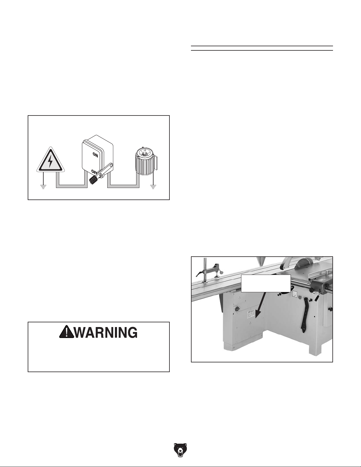
1. DISCONNECT MACHINE FROM POWER!
2. Using a 4mm hex wrench, remove electri-
cal panel cover (see Figure 6) from back of
frame.
Electrical Panel
Cover
Serious injury could occur if you connect
machine to power before completing setup
process. DO NOT connect to power until
instructed later in this manual.
Extension Cords
Model G0764 (Mfd. Since 02/14)
Figure 6. Electrical panel cover location.
-17-
Page 20
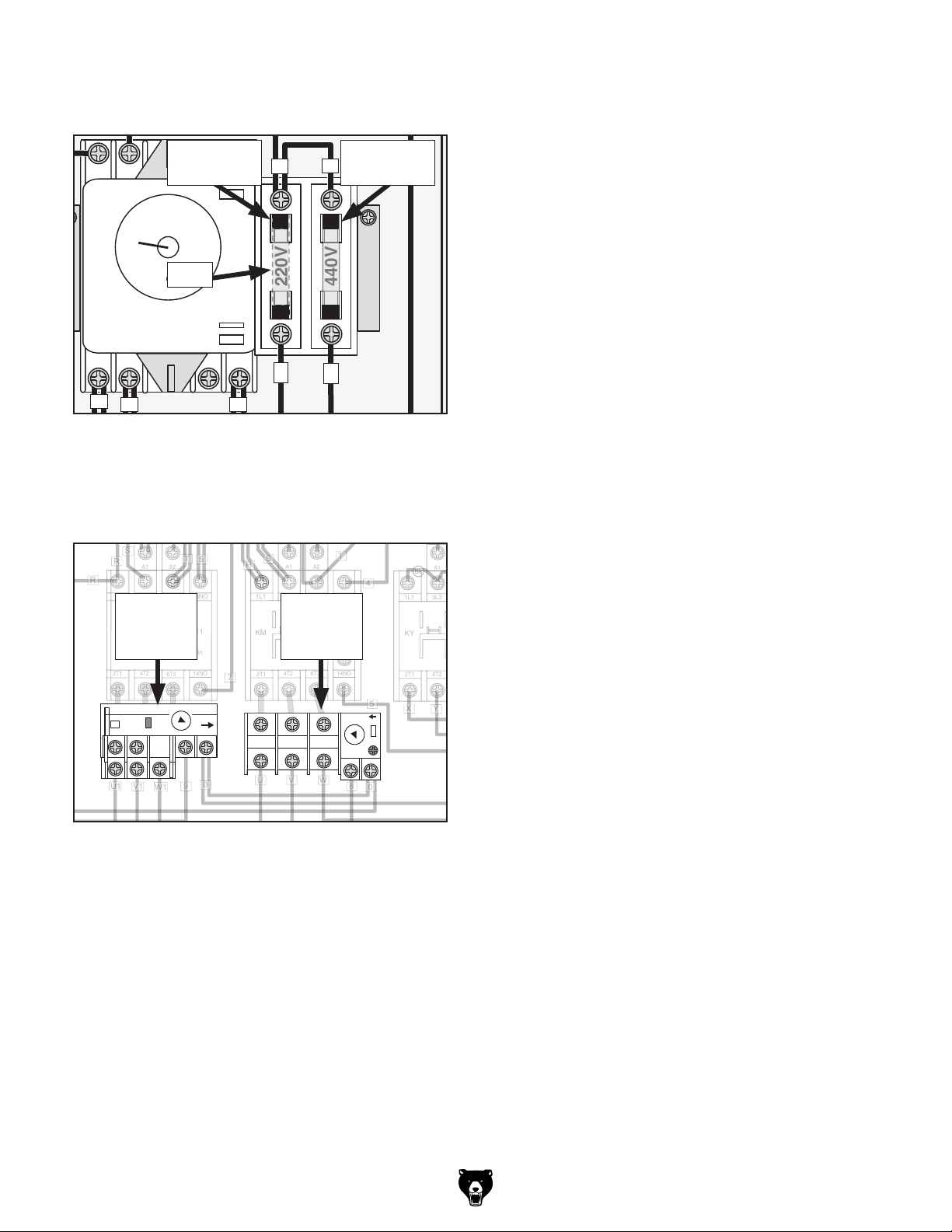
3. Remove fuse from “220V” holder and insert it
5
4
7
12
5
5
5
7
1L1
5L3
13NO
3L2
2T1
6T3
4T2
14NO
A2
A1
A2
A1
S-P11
KS
Shihlin
1L1
5L3
13NO
3L2
21NC
2T1
6T3
4T2
22NC
14NO
Shihlin
S-P21
KM
A2
A1
1L1
5L3
13NO
3L2
21NC
2T1
6T3
4T2
22NC
14NO
Shihlin
S-P21
KY
A2
A1
1L1
5L3
13NO
3L2
21NC
2T1
6T3
4T2
22NC
14NO
Shihlin
S-P21
KD
654
3
781
2
220V
440V
220V
STAR-DELTA TIMER
TYPE TRD-N
ANLY
SECONDS
0
5
101520
25
30
RST
0
1
1
4
5
5
4
7
T
220
220
440
Ground
Ground
0
E
E
10
10
12
R
12
R
R
R
S
7
7
9
9
T
T
5
5
5RS
R
S
88T
T
0
5
13
13
0
220
440
0
24
0
220
440
0
24
0
11
11
0
0
0
W1
014
5
7
RST
E
E
U
V
W
440
0
LCE
TBSM-100040
U1
V1
XYZ
XYZ
into “440V” holder (see illustration in Figure 7).
5. Replace right overload relay with Shihlin
TH-P20 overload relay, and set amperage
dial to 15A (see Figure 8).
220V Fuse
6 5 4 3
Holder
R
440V Fuse
R
Holder
ANLY
15
10
20
5
0
SECONDS
25
30
Fuse
220V
220V
440V
STAR-DELTA TIMER
TYPE TRD-N
7 8 1 2
220
440
0
Figure 7. Moving fuse to “440V” fuse holder.
4. Replace left overload relay with Shihlin
TH-P12 overload relay, and set amperage
dial to 1.7A (see Figure 8).
6. Open motor cabinet door on back of saw.
7. Rewire main blade and scoring blade motors
to 440V. Refer to wiring diagrams on Pages
90–91.
8. Close motor cabinet door and replace electri-
cal panel cover.
9. After Setup and Assembly procedures are
completed, connect machine to power, as
instructed on Page 38.
1L1
TH-P20
Overload
Relay
5L3
3L2
12
TH-P20
15
RCA
96
TH-P12
Overload
Relay
RESET TRIP
H A
U V W
2.1
1.3
1.7
RCA
96959798
Figure 8. Overload relays for 440V.
TRIP
18
RESET
95
-18-
Model G0764 (Mfd. Since 02/14)
Page 21
SECTION 3: SETUP
Your machine was carefully packaged for safe
transportation. Remove the packaging materials
from around your machine and inspect it. If you
discover any damage, please call us immediately
at (570) 546-9663
Save the containers and all packing materials for
possible inspection by the carrier or its agent.
Otherwise, filing a freight claim can be difficult.
When you are completely satisfied with the condition of your shipment, inventory the contents.
Keep children and pets away
from plastic bags or packing
materials shipped with this
Needed for Setup
This machine presents
serious injury hazards
to untrained users. Read
through this entire manual to become familiar with
the controls and operations before starting the
machine!
Wear safety glasses during
the entire setup process!
HEAVY LIF T!
Straining or crushing injury
may occur from improperly
lifting machine or some of
its parts. To reduce this risk,
get help from other people
and use a forklift (or other
lifting equipment) rated for
weight of this machine.
The following are not included, but needed to
properly complete the setup process.
Description Qty
• Additional People ....................................... 4
• Safety Glasses ........................ 1 Per Person
• Cleaner/Degreaser (Page 23) .... As Needed
• Disposable Shop Rags ............... As Needed
• Forklift (Rated for at least 2000 lbs.) .......... 1
• Straightedge 4' ........................................... 1
• Level ........................................................... 1
• Screwdriver Phillips #2 ............................... 1
• Screwdriver Flat Head #2 ........................... 1
• Saw Blade 14" (Page 67) ........................... 1
• Dust Collection System w/5" branch line ... 1
• Dust Hose 5" (Page 68) ............................. 1
• Dust Hose 2
• Hose Clamp 5" (Page 68) .......................... 1
• Hose Clamp 2
1
⁄2 " (Page 68) .......................... 1
1
⁄2 " (Page 68) ....................... 1
Unpacking
Model G0764 (Mfd. Since 02/14)
for advice.
SUFFOCATION HAZARD!
machine. Discard immediately.
-19 -
Page 22
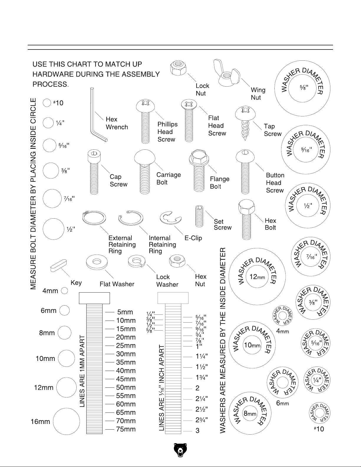
Hardware Recognition Chart
-20-
Model G0764 (Mfd. Since 02/14)
Page 23
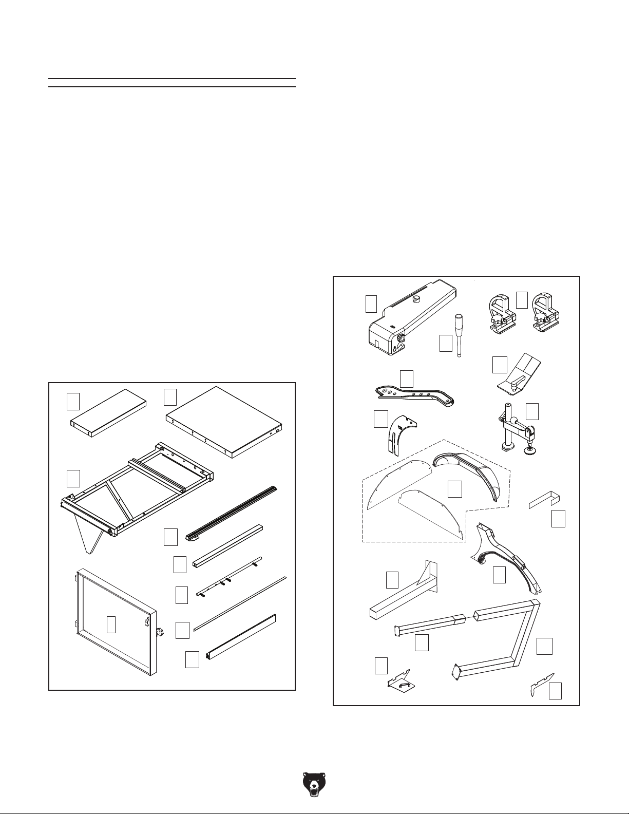
Inventory
These are the “loose” components shipped with
the machine. Before setup, lay them out to make
sure you have everything listed below.
If any non-proprietary parts are missing (e.g. a
nut, bolt, or washer), we will gladly ship them upon
verification of order. For the sake of expediency,
you can also get replacement parts at your local
hardware store.
Inventory (Figure 9) Qty
A. Small Extension Table ................................ 1
B. Large Extension Table ............................... 1
C. Crosscut Table ........................................... 1
D. Crosscut Fence .......................................... 1
E. Crosscut Table Brace ................................. 1
F. Rip Fence Rail w/Fasteners ....................... 1
G. Rip Fence Scale ......................................... 1
H. Rip Fence ................................................... 1
I. Cabinet Door .............................................. 1
Inventory (Figure 10) Qty
J. Rip Fence Body Assembly ......................... 1
K. Push Handle ............................................... 1
L. Crosscut Fence Flip Stops ......................... 2
M. Edge Shoe Assembly ................................. 1
N. Push Stick .................................................. 1
O. Riving Knife ................................................ 1
P. Hold-Down Assembly ................................ 1
Q. Blade Guard Cover Assembly .................... 1
R. Blade Guard Arm Brace ............................. 1
S. Blade Guard Cover Bracket ....................... 1
T. Blade Guard Arm (Lower Section) ............. 1
U. Blade Guard Arm (Upper Section) ............. 1
V. End Plate w/Handle (Sliding Table) ............ 1
W. Blade Guard Arm (Middle Section) ............ 1
X. End Plate (Sliding Table) ............................ 1
J
K
N
L
M
A
C
I
Figure 9. G0764 Inventory 1.
B
D
E
F
G
O
Q
T
U
H
V
Figure 10. G0764 Inventory 2.
S
P
R
W
X
Model G0764 (Mfd. Since 02/14)
-21-
Page 24
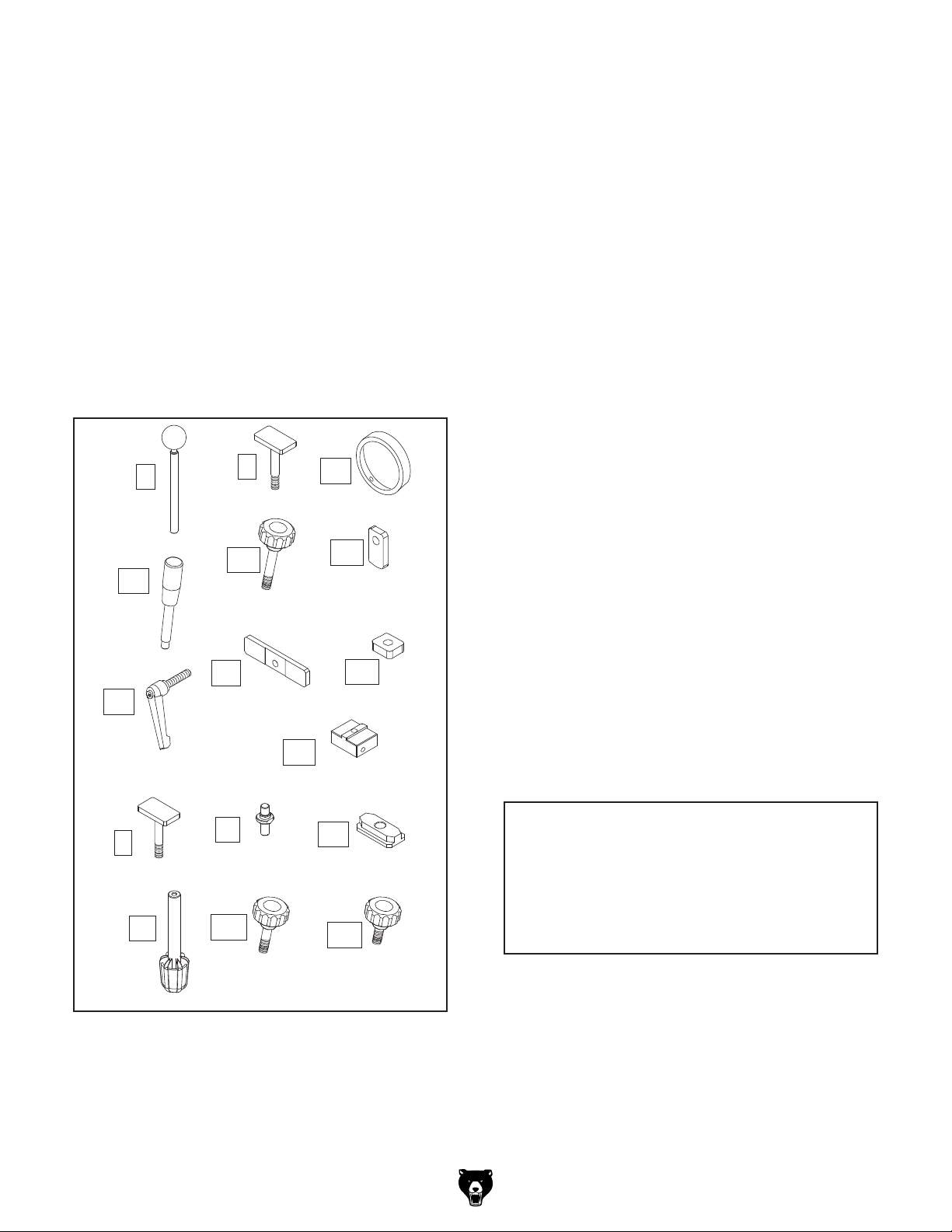
Y. Blade Locking Tool ..................................... 1
Z. T-bolts M12-1.75 x 50.................................. 3
AA. Rip Fence Rail Stop Ring ........................... 1
BB. Locking Handles M10-1.5 x 12 ................... 2
CC. Knob Bolt M10-1.5 x 70 .............................. 1
DD. Rip Fence End Stop ................................... 1
EE. Adjustable Handle M12-1.75 x 55 ............... 1
FF. T-Nut Plate M12-1.75 .................................. 1
GG. T-N uts M8-1.25 ........................................... 5
HH. 90° Stop Block............................................ 1
II. T-Bolt M8-1.25 x 35 .................................... 1
JJ. Pivot Bolt M8-1.25 ...................................... 1
KK. T-Slot Plate M8-1.25 ................................... 1
LL. Long Knobs M8-1.25 .................................. 2
MM.Knob Bolt M8-1.25 x 50 .............................. 3
NN. Knob Bolt M8-1.25 x 25 w/Nylon Tip .......... 1
EE
BB
Y
Z
CC
FF
AA
DD
GG
HH
Component Hardware (not shown) Qty
Combo Wrenches 19, 30mm (Toolbox) ........1 Ea
Wrench 24 x 27mm Open-Ends (Toolbox) ........ 1
Lock Washers 12mm (Sliding Table) ................. 3
Flat Washers 12mm (Sliding Table) ................... 3
Hex Nuts M12-1.75 (Sliding Table) ..................... 3
T-Nut M12-1.75 (Push Handle) ........................... 1
B.H. Cap Screws M6-1 x 12 (Rip Fence Scale) 3
Flat Washers 6mm (Rip Fence Scale) .............. 4
Hex Nuts M6-1 (Rip Fence Scale) ..................... 1
Cap Screw M8-1.25 x 15 (Rip Fence Rail) ........ 1
Lock Washer 8mm (Rip Fence Rail) ................. 1
Flat Washer 12mm (Crosscut Table) ................. 1
Flat Washers 8mm (Crosscut Brace) ................ 2
Cap Screw M8-1.25 x 35 (Crosscut Fence) ...... 1
Lock Washer 8mm (Crosscut Fence) ................ 1
Flat Washer 8mm, Fiber (Crosscut Fence) ....... 1
Fender Washer 8mm (Crosscut Fence) ............ 1
Studs M20-2.5 x 130 (Lower Guard Arm) ......... 2
Flat Washers 20mm (Lower Guard Arm)........... 2
Hex Nuts M20-2.5 (Lower Guard Arm) .............. 2
Cap Screws M8-1.25 x 25 (Middle Guard Arm) 4
Flat Washers 8mm (Middle Guard Arm) ............ 4
Lock Washers 8mm (Middle Guard Arm) .......... 4
Set Screws M6-1 x 12 (Middle Guard Arm) ....... 4
B.H. Cap Screw M10-1.5 x 25 (Guard Brace) .... 1
Set Screws M8-1.25 x 16 (Guard Brace) ........... 4
Hex Nuts M8-1.25 (Guard Brace) ...................... 4
Flat Washers 10mm (Guard Brace) ................... 2
Hex Nut M10-1.5 (Guard Brace) ........................ 1
B.H. Cap Screws M4-.7 x 6 (Guard Cover) ..... 12
Cap Screws M6-1 x 12 (Guard Cover) .............. 4
Lock Washers 6mm (Guard Cover) ................... 4
Flat Washers 6mm (Guard Cover) .................... 4
Lock Handle M10-1.5 x 35 (Middle Guard Arm) 1
-22-
II
LL
Figure 11. G0764 Inventory 3.
JJ
MM
KK
NN
NOTICE
If you cannot find an item on this list, carefully check around/inside the machine and
packaging materials. Often, these items get
lost in packaging materials while unpacking or they are pre-installed at the factory.
Model G0764 (Mfd. Since 02/14)
Page 25
The unpainted surfaces of your machine are
coated with a heavy-duty rust preventative that
prevents corrosion during shipment and storage.
This rust preventative works extremely well, but it
will take a little time to clean.
Be patient and do a thorough job cleaning your
machine. The time you spend doing this now will
give you a better appreciation for the proper care
of your machine's unpainted surfaces.
There are many ways to remove this rust preventative, but the following steps work well in a wide
variety of situations. Always follow the manufacturer’s instructions with any cleaning product you
use and make sure you work in a well-ventilated
area to minimize exposure to toxic fumes.
Before cleaning, gather the following:
• Disposable rags
• Cleaner/degreaser (WD•40 works well)
• Safety glasses & disposable gloves
• Plastic paint scraper (optional)
Basic steps for removing rust preventative:
1.
2.
3.
4.
Many cleaning solvents
work in a well-ventilated
Avoid chlorine-based solvents, such as
Cleanup
Gasoline and petroleum
products have low flash
points and can explode
or cause fire if used to
clean machinery. Avo i d
using these products
to clean machinery.
Put on safety glasses.
Coat the rust preventative with a liberal
amount of cleaner/degreaser, then let it soak
for 5–10 minutes.
Wipe off the surfaces. If your cleaner/degreas-
er is effective, the rust preventative will wipe
off easily. If you have a plastic paint scraper,
scrape off as much as you can first, then wipe
off the rest with the rag.
are toxic if inhaled. Only
area.
NOTICE
acetone or brake parts cleaner, that may
damage painted surfaces.
T23692—Orange Power Degreaser
A great product for removing the waxy shipping
grease from your machine during clean up.
Figure 12. T23692 Orange Power Degreaser.
Repeat Steps 2–3 as necessary until clean,
then coat all unpainted surfaces with a quality
metal protectant to prevent rust.
Model G0764 (Mfd. Since 02/14)
-23-
Page 26
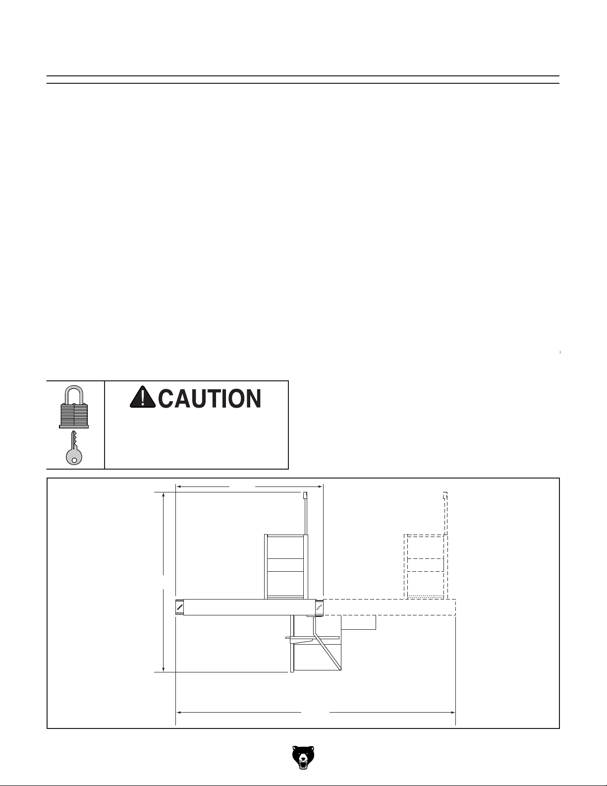
Site Considerations
Physical Environment
The physical environment where the machine is
operated is important for safe operation and lon-
gevity of machine components. For best results,
operate this machine in a dry environment that is
free from excessive moisture, hazardous chemi-
cals, airborne abrasives, or extreme conditions.
Extreme conditions for this type of machinery are
generally those where the ambient temperature
range exceeds 41°–104°F; the relative humidity
range exceeds 20%–95% (non-condensing); or
the environment is subject to vibration, shocks,
Place this machine near an existing power source.
traffic, material handling, moisture, chemicals, or
other hazards. Make sure to leave enough space
around machine to disconnect power supply or
Lighting around the machine must be adequate
enough that operations can be performed safely.
Shadows, glare, or strobe effects that may distract
Machine Data Sheet for the weight
or bumps.
Electrical Installation
Make sure all power cords are protected from
Children or untrained people
may be seriously injured by
this machine. Only install in an
access restricted location.
133"
203"
apply a lockout/tagout device, if required.
Lighting
-24-
279"
Figure 13. Minimum working clearances.
Model G0764 (Mfd. Since 02/14)
Page 27
Lifting & Placing
get help from other people
Saw
HEAVY LIF T!
Straining or crushing injury
may occur from improperly
lifting machine or some of
its parts. To reduce this risk,
and use a forklift (or other
lifting equipment) rated for
weight of this machine.
To lift and place saw:
1. Position crate as close to installation location
as possible.
3. Remove small items packed around saw and
unbolt saw from pallet.
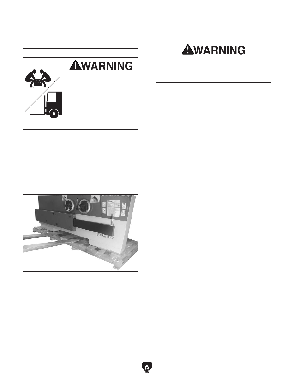
DO NOT lift saw any higher than necessary
to clear pallet. Serious personal injury and
machine damage may occur if safe moving
methods are not followed.
4. With an assistant holding each end to help
stabilize load, lift saw with forklift just high
enough to clear pallet, and move it to your
predetermined location.
5. Lower saw onto ground and back forklift
away.
2. Remove top of crate. Position forklift forks as
wide as they can be while still fitting under
center opening (see Figure 14).
Figure 14. How to insert forks for lifting table
saw off pallet.
Model G0764 (Mfd. Since 02/14)
-25-
Page 28
Assembly
The sliding table weighs nearly 200 pounds. It
must be lifted and carefully positioned onto saw
frame during assembly. If you are using a forklift
to lift and place it, you'll need to use lifting slings
around table to prevent scratching the aluminum
surface.
If you are not able to use the described forklift
method, the sliding table can be lifted into place
by four strong people—with one lifting from each
corner.
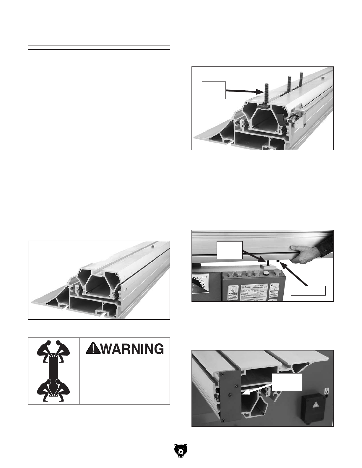
2. Insert (3) M12-1.75 x 60 T-bolts into T-slot
along bottom of sliding table (see Figure 16),
and space them the same distance apart as
mounting holes in cabinet frame.
T-Bolt
(1 of 3)
The only other part of the assembly that requires
additional help is installation of the extension
tables and blade guard arm. It takes approximately two hours to assemble the saw and make
the required adjustments to prepare the saw for
the test run.
To assemble sliding table saw:
1. Turn sliding table upside down, as shown in
Figure 15.
Figure 16. T-slot along bottom of table.
3. Lift sliding table over saw and lower T-bolts
into mounting holes on frame, as shown in
Figure 17.
Note: Make sure cap screw shown in Figure
17 is on outside of cabinet frame and against
mount edge.
T-Bolt
(1 of 3)
Cap Screw
Figure 17. Inserting T-bolt into mounting hole on
saw frame.
Figure 15. Sliding table turned upside down.
Lifting heavy machinery
or parts without proper
assistance or equipment
may result in strains, back
injuries, crushing injuries,
or property damage.
-26-
4. Remove shipping bracket shown in Figure
18. Keep screws for use in a later step.
Shipping
Bracket
Figure 18. Example of shipping bracket that
must be removed.
Model G0764 (Mfd. Since 02/14)
Page 29
5. Install end plate with handle, as shown in
Figure 19, using the screws pre-installed in
this location on the sliding table and those
removed in Step 4.
End Plate
w/Handle
Figure 19. Slide table control end handle.
6. Position sliding table against parallelism
adjustment bolts at each end (see Figure 20).
Parallelism Adjustment Bolt
(1 of 2)
Sliding Table
Figure 20. Sliding table parallelism adjustment
bolt (1 of 2).
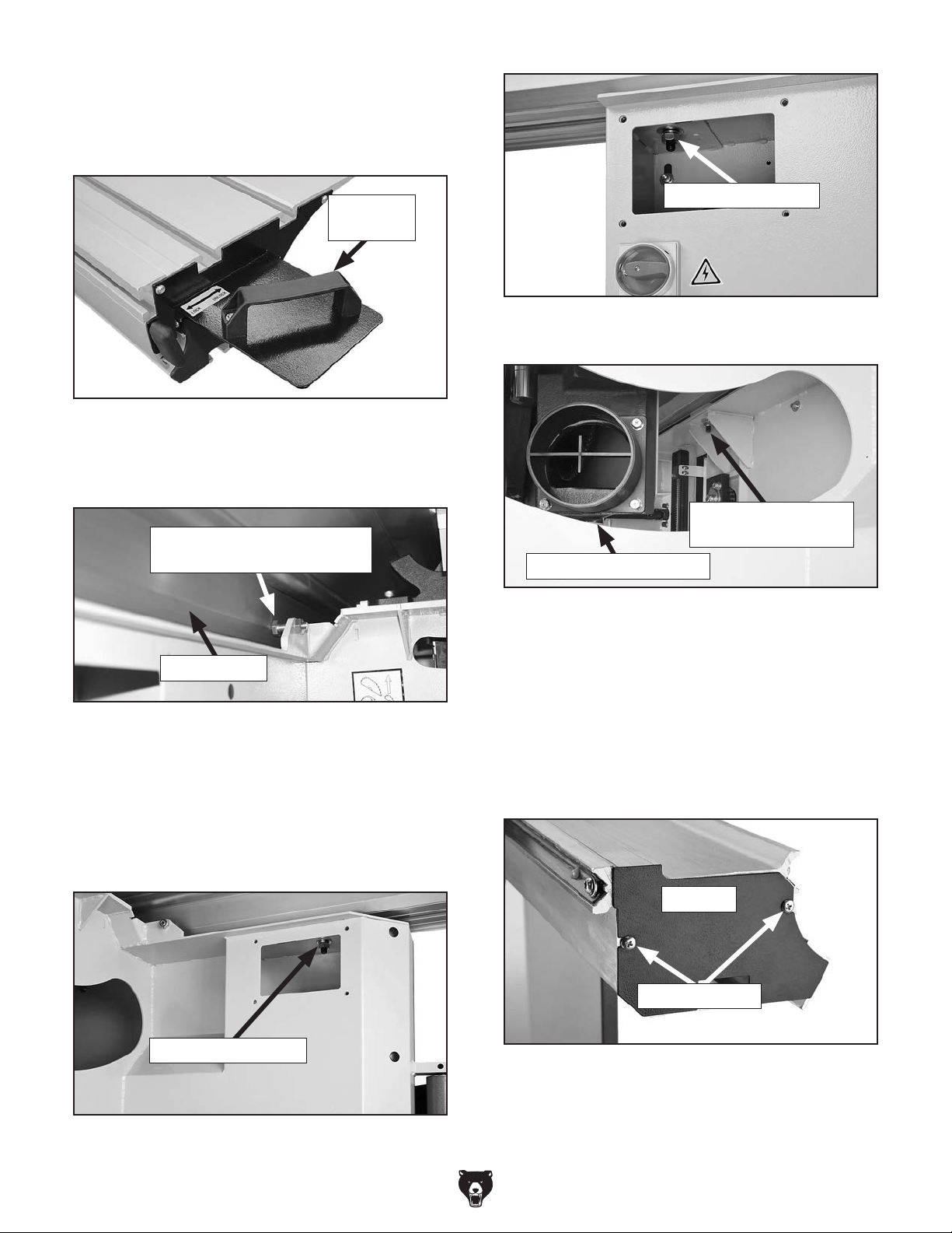
7. Remove access covers on each side of the
frame to reach the T-bolts on the ends of the
sliding table (Figures 21–22). Reach through
cabinet access hole to reach middle sliding
table T-bolt (Figure 23).
Sliding Table T-bolt
Figure 22. Sliding table T-bolt access on rear
side at front of saw.
Sliding Table T-bolt
(Middle)
Cabinet Access Hole
Figure 23. Sliding table middle T-bolt access.
8. Put (3) M12-1.75 hex nuts, (3) 12mm lock
washers, and (3) 12mm flat washers on end
of each T-bolt and tighten to secure sliding
table to frame (as shown in Figures 21–23).
9. Attach end cap (as shown in Figure 24) with
Phillips screws already threaded into those
same holes on the sliding table.
Sliding Table T-Bolt
Figure 21. Sliding table T-bolt access on rear
side at back of saw.
Model G0764 (Mfd. Since 02/14)
End Cap
Phillips Screws
Figure 24. End cap secured on sliding table with
Phillips screws.
-27-
Page 30
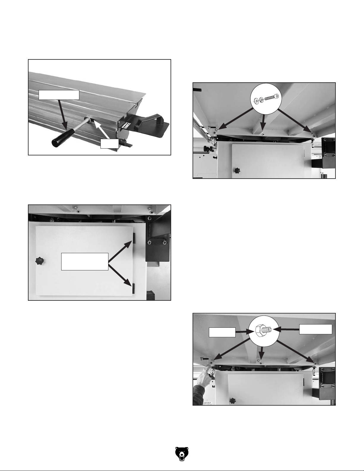
10. Thread M12-1.75 T-nut onto end of push
handle and slide T-nut into T-slot at front end
of sliding table, as shown in Figure 25.
Push Handle
T-nut
Figure 25. Push handle attached to sliding table.
11. Attach the cabinet door by sliding hinge
sleeves over pins of already attached hinge
(see Figure 26).
12. Attach large extension table to cast iron table
using (3) pre-installed M10-1.5 x 25 cap
screws, 10mm lock washers, and 10mm flat
washers (see Figure 27). Only hand tighten
cap screws for now. They will be fully tightened in a later step.
Figure 27. Underside view of large extension
table attached to cabinet.
Hinge Sleeves
& Pins
Figure 26. Cabinet door attached on hinges.
13. Place a straightedge across cast-iron table
and large extension table to see if tables are
parallel.
—If entire length of straight edge is parallel
with both tables move on to Step 14.
—If both tables are not parallel with straight
edge, loosen hex nuts on set screws
shown in Figure 28. Adjust set screws
to align top of extension table with top of
cast-iron table, then retighten hex nuts to
secure setting.
Hex Nut
Set Screw
-28-
Figure 28. Location of set screws and hex nuts
used to level extension table.
Model G0764 (Mfd. Since 02/14)
Page 31

14. Fully tighten cap screws from Step 12.
17. Fully tighten cap screws from Step 15.
15. Attach small extension table to cast iron
table using (2) pre-installed M10-1.5 x 25 cap
screws, 10mm lock washers, and 10mm flat
washers (see Figure 29). Only hand tighten
cap screws for now. They will be fully tightened in a later step.
Figure 29. Underside view of large extension
table attached to cabinet.
18. Attach rip fence scale flush along top edge of
cast iron table and large extension table (see
Figure 31) with (4) M6-1 x 12 button head
cap screws, (8) 6mm flat washers, and (4)
M6-1 hex nuts.
Rip Fence
Scale
x 4
Figure 31. Rip fence scale attached flush with
top edge of cast-iron table and large extension
table.
16. Place a straightedge across cast-iron table
and large extension table to see if tables are
parallel.
—If entire length of straight edge is parallel
with both tables move on to Step 17.
—If both tables are not parallel with straight
edge, loosen hex nuts on set screws
shown in Figure 30. Adjust set screws
to align top of extension table with top of
cast-iron table, then retighten hex nuts to
secure setting.
Hex Nut
Set Screw
19. The rip fence rail is pre-assembled with
four rail studs and accompanying hardware.
Remove (1) hex nut, (1) flat washer, and (1)
lock washer from end of each stud, as shown
in Figure 32.
Figure 32. Removing rip fence rail hardware to
prepare for installation.
Figure 30. Location of set screws and hex nuts
used to level extension table.
Model G0764 (Mfd. Since 02/14)
-29-
Page 32

20. Insert studs into tables as shown in Figure 33,
and re-install hardware removed in Step 20.
23. Slide rip fence onto clamping plate as shown
in Figure 35, and lock it with slide lock handle.
Slide Lock
Handle
Clamping
Plate
Rip
Fence
Figure 35. Rip fence attached to rip fence base.
24. Open cabinet door and remove the board that
braces the scoring motor.
Figure 33. Installing the rip fence rail.
21. Slide rip fence base onto fence rail as shown
in Figure 34.
22. Thread (2) M10-1.5 x 12 lock handles and
M10-1.5 x 70 lock knob bolt into rip fence
base, as shown in Figure 34.
Fence Base
Knob
Bolt
Lock
Handles
25. Tilt blades to 0˚ and raise main blade all the
way up.
26. Lift scoring motor and install flat belt on motor
and arbor pulleys (see Figure 36) so that
arrow on side of belt closest to main motor is
pointed down.
Note: The belt tension automatically adjusts
when the scoring motor is released.
Flat Belt
Figure 34. Rip fence attached with lock handles
and lock knob installed.
-30-
Figure 36. Flat belt installed on scoring motor
and arbor pulleys (table removed for clarity).
Model G0764 (Mfd. Since 02/14)
Page 33

27. Release belt adjustment handle (see Figure
37) and rotate motor adjustment lever clock-
wise to adjust motor and tension belt.
30. Push down on blade locking tool with one
hand as you rotate arbor clockwise with
wrench on arbor bolt. This will force blade
locking tool into arbor indent and prevent
arbor from rotating in next steps.
Motor Adjustment
Handle
Figure 37. Location of motor adjustment handle
and motor adjustment lever.
28. Move sliding table all the way forward to
expose blade cover, then flip cover locks (see
Figure 38) up to open.
Motor Adjustment
Lever
31. Continue unthreading arbor bolt clockwise (it
has left-hand threads) until you can remove
arbor bolt, arbor bushing, and flange (see
Figure 40).
Flange
Figure 40. Main blade arbor parts and tools for
changing blade.
Before proceeding with the next steps, wear
gloves to protect your hands when handling
and installing the blade.
Arbor
Bushing
Arbor
Bolt
Blade Cover Locks
Figure 38. Location of blade cover locks.
29. Insert arbor blade locking tool into access
hole shown in Figure 39.
Main Blade
Locking Hole
Arbor
Bolt
Figure 39. Loosening main blade arbor bolt.
Model G0764 (Mfd. Since 02/14)
The Model G0764 does not ship with a 14"
main blade. Refer to Blade Requirements
and Blade Selection beginning on Page 46
when purchasing the main blade.
32. Slide main blade (not included) over arbor
with teeth facing to the right, then install
flange.
-31-
Page 34

33. Align arbor bushing lugs with arbor keyways
(see Figure 41) as you slide bushing onto
arbor.
Flange
39. Install rip fence end stop on opposite end of
rip fence rail with (1) M8-1.25 x 15 cap screw
and (1) 8mm lock washer (see Figure 43).
Rip Fence
End Stop
Arbor
Bolt
Arbor
Arbor
Bushing
Figure 41. Main blade component assembly.
34. Thread arbor bolt on counterclockwise and
fully tighten it to secure the blade.
35. Install and align riving knife (refer to Riving
Knife Alignment beginning on Page 45 for
detailed information).
36. Close blade cover. Center sliding table and
lock in place.
1
37. Position rip fence
⁄8" away from main blade.
38. Slide rip fence stop ring onto end of rail
and tighten set screw to secure it in place
(see Figure 42). When installed correctly,
this ring will prevent rip fence from contacting
blade.
Figure 43. Rip fence end stop attached to rail.
40. Adjust rip fence to main blade and tables as
instructed in Calibrating Rip Fence on Page
82.
41. Thread M12-1.75 x 55 lock handle with a
12mm flat washer through hole in short side
of crosscut table and into a M12-1.75 T-nut
plate, as shown in Figure 44.
Flat Washer
Lock
Handle
T-Nut
Plate
Rip Fence
Stop Ring
w/Set Screw
Figure 42. Rip fence stop ring attached to rail.
-32-
Figure 44. Crosscut lock handle installed on
crosscut table.
Model G0764 (Mfd. Since 02/14)
Page 35

42. With assistance from other people, place
crosscut table on swing arm pivot pin and
slide T-nut plate into sliding table T-slot, as
shown in Figure 45.
44. Secure table brace by threading (2) M8-1.25
x 50 knob bolts with (2) 8mm flat washers into
brace T-nuts (see Figure 46).
45. Turn crosscut fence onto its side.
Crosscut Table
T-Slot
Figure 45. Attaching crosscut table to machine
frame.
43. Slide (2) M8-1.25 T-nuts into crosscut table
brace T-slots, and align them with center
holes in crosscut table (see Figure 46).
Swing Arm
Pivot Pin
T-Nut Plate
46. On crosscut fence end nearest blade:
a. Insert (1) M8-1.25 T-nut into T-slot, then
loosely thread M8-1.25 pivot bolt with
8mm fiber flat washer into T-nut (see
Figure 47).
End Cap
T-Nut, Pivot Bolt,
& Fiber Flat Washer
Figure 47. Crosscut fence hardware near to
blade.
b. Position crosscut fence so edge cap (see
Figure 47) is close to but not touching
main blade.
Long Knob
& Fender Washer
Pivot
Hole
Crosscut Table Brace
Figure 46. Example of table brace attached to
crosscut table.
Model G0764 (Mfd. Since 02/14)
c. Align the pivot bolt with pivot hole (see
Figure 47), then fully tighten pivot bolt.
Note: Long knob and fender washer will
help secure crosscut fence in later step.
-33-
Page 36

47. In middle of crosscut fence:
a. Insert M8-1.25 x 40 T-bolt into T-slot (see
Figure 48).
49. Without moving previously installed hard-
ware, flip crosscut fence over and insert pivot
bolt and T-slot bolt into appropriate hole/slot.
50. Secure crosscut fence to crosscut table by:
Long Knob w/ Fender Washer & T-Slot Plate
Scale
T-Bolt
Figure 48. Crosscut fence hardware in the
middle.
b. Align T-slot bolt with slot in pre-installed
scale bar (see Figure 48).
Note: Long knob and fender washer will
help secure crosscut fence in later step.
48. On end of crosscut fence farthest from blade:
Bar
a. From underneath left side of crosscut
fence, threading M8-1.25 long knob with
8mm fender washer onto pivot bolt.
b. From underneath middle of crosscut
fence, positioning M8-1.25 T-slot plate
in scale bar slot, then threading M8-1.25
long knob with 8mm fender washer onto
previously installed T-slot bolt.
c. On the right side of crosscut fence, mak-
ing sure 90° stop block is against stop
bolt, then securing fence by threading
M8-1.25 x 50 knob bolt into threaded hole
on stop block.
51. Slide crosscut fence extension out, as shown
in Figure 50.
52. Attach flip stops onto long side of crosscut
fence by sliding T-nuts into T-slots on fence
and tightening the knob bolts (see Figure 50).
a. Insert M8-1.25 T-nut into T-slot
b. Attach 90° stop block to T-nut with
M8-1.25 x 35 cap screw and 8mm lock
washer so that it is aligned with stop bolt
(see Figure 49).
Note: Make sure threaded hole in stop
block is on the right of cap screw.
T-Nut, 90° Stop Block,
Cap Screw, & Lock Washer
Stop
Bolt
Stop Block
Knob Bolt
Fence Extension
Flip Stop T-Nut
Figure 50. Flip stop attached to crosscut fence.
-34-
Figure 49. 90° stop block installed.
Model G0764 (Mfd. Since 02/14)
Page 37

53. From underneath right end of crosscut fence,
insert M8-1.25 T-nut into crosscut fence
T-slot, then thread M8-1.25 x 25 knob bolt
with nylon tip through T-nut and into placement hole (see Figure 51). This secures
crosscut extension fence in place.
56. Use level and adjustment bolt and hex nut
shown in Figure 52 to level lower guard arm,
then fully tighten stud hex nuts.
57. Loosely attach middle guard arm to lower
guard arm with (4) M8-1.25 x 25 cap screws,
(4) 8mm lock washers, and (4) 8mm flat
washers (see Figure 53).
Knob
Bolt
Placement Hole
Figure 51. Knob bolt and placement hole
(viewed from underneath crosscut fence).
54. Thread (2) M20-2.5 x 130 studs through front
side of cabinet wall and into welded hex nuts.
(Refer to Figure 52 for location).
55. Slide lower guard arm over studs, then finger
tighten (2) M20-2.5 hex nuts with (2) 20mm
flat washer onto studs (see Figure 52). Make
sure connecting flange faces up.
Middle
Guard Arm
x 4
Figure 53. Middle section of guard arm attached
to lower section.
58. Thread (4) M8-1.25 x 12 set screws into
threaded holes next to cap screws installed
in Step 57.
59. Use a level and set screws to level middle
guard arm.
x 4
Adjustment Bolt
Connecting Flange
Studs,
Flat Washer,
& Hex Nuts
Figure 52. Lower guard arm attached.
Model G0764 (Mfd. Since 02/14)
& Hex Nut
60. Slide blade guard arm brace shown in Figure
54 around middle guard arm, and secure it to
extension table with (1) M10-1.5 x 25 button
head cap screw, (1) 10mm flat washer, and
(1) M10-1.5 hex nut.
Brace
x 4
Figure 54. Arm brace attached to middle guard
arm and extension table.
-35-
Page 38

61. Thread (4) M8-1.25 x 16 set screws with
(4) 8mm hex nuts through blade guard arm
brace (see Figure 54).
62. Use a level and set screws to make sure
middle guard arm is vertically level, then fully
tighten hex nuts on set screws.
63. Fully tighten cap screws installed in Step 57.
64. Attach upper guard arm to blade guard
assembly with (4) M6-1 x 12 cap screws, (4)
6mm lock washers, and (4) 6mm flat washers
(see Figure 55).
Upper
Guard Arm
66. Attach left flat blade cover with (6) M4-.7 x 6
button head cap screws (see Figure 57).
Left Flat Blade
Cover
x 6
Figure 57. Left flat blade cover installed.
67. Install flat blade cover for straight cuts, or
bubbled cover for angled cuts, using (6)
M6-.7 x 6 button head cap screws (see
Figure 58).
x 4
Blade Guard
Assembly
Figure 55. Upper guard arm attached to blade
guard.
65. Slide upper guard arm into middle guard arm,
centering blade guard over blade (see Figure
56).
Middle Guard Arm
Upper Guard Arm
Lock Handle
x 6
Figure 58. Right flat blade cover installed.
68. Secure upper guard in place with M10-1.5 x
35 lock handle (see Figure 58).
Right Flat
Blade Cover
Figure 56. Blade guard installed onto middle
arm.
-36-
Model G0764 (Mfd. Since 02/14)
Page 39

Dust Collection
This machine creates substantial amounts
of dust during operation. Breathing airborne dust on a regular basis can result in
permanent respiratory illness. Reduce your
risk by wearing a respirator and capturing
the dust with a dust collection system.
2. Fit 2 1⁄2" dust hose over dust port on blade
guard, as shown in Figure 60, then secure it
in place with a hose clamp.
1
Important: Secure 2
⁄2" dust hose to upper
guard arm (e.g., with cable tie) so that it will
not become entangled with workpiece or
blade during operations.
Minimum CFM at 5" Dust Port: 615 CFM
1
Minimum CFM at 2
⁄2" Dust Port: 150 CFM
Do not confuse this CFM recommendation with
the rating of the dust collector. To determine the
CFM at the dust port, you must consider these
variables: (1) CFM rating of the dust collector,
(2) hose type and length between the dust collector and the machine, (3) number of branches
or wyes, and (4) amount of other open lines
throughout the system. Explaining how to calculate these variables is beyond the scope of
this manual. Consult an expert or purchase a
good dust collection "how-to" book.
To connect dust collection hoses:
1. Fit 5" dust hose over dust port on rear side of
cabinet, as shown in Figure 59, and secure
with hose clamp.
Hose
Clamp
Cable Tie
Figure 60. 2 1⁄2" dust hose attached to blade
guard.
1
3. Connect 5" and 2
⁄2" dust hoses to a Y-fitting,
then attach it to a single dust collection
branch line.
4. Tug on dust hoses to make sure they do not
come off. A tight fit is necessary for proper
performance.
Figure 59. 5" dust hose attached to dust port.
Model G0764 (Mfd. Since 02/14)
-37-
Page 40

Before the machine can be connected to the
power source, an electrical circuit and connection device must be prepared per the POWER
SUPPLY
setup instructions in this manual must be complete to ensure that the machine has been assembled and installed properly. The disconnect switch
installed by the electrician (as recommended) is
the primary means for disconnecting or connecting the machine to the power source.
Move the disconnect switch handle to the ON
position, as illustrated below. The machine is now
connected to the power source.
Move the disconnect switch handle to the OFF
position, as illustrated below. The machine is now
disconnected from the power source.
Note:
Lock the switch in the OFF position to
restrict others from starting the machine.
Electrocution, fire, or
equipment damage may
occur if machine is not
correctly grounded and
connected to the power
Power Connection
section in this manual; and all previous
supply.
Note About Phase Converters: Due to the start-
up load from this machine, we do not recommend
using a static phase converter to create 3-phase
power—as it can quickly decrease the life of electrical components on this machine. If you must
use a phase converter, only use a rotary phase
converter. Only connect the manufactured leg or
"wild wire" to the S terminal (see location on Page
84). The S terminal can handle power fluctuation
because it is wired directly to the motor.
To connect saw to power:
Figure 61. Connecting power to machine.
1. Remove power junction box cover (see
Figure 63).
Power Junction
Box
Strain Relief
Figure 63. Location of junction box.
2. Insert incoming power wires through strain
relief in bottom of power junction box.
Figure 62. Disconnecting power from machine.
-38-
Model G0764 (Mfd. Since 02/14)
Page 41

Once assembly is complete, test run the machine
to ensure it is properly connected to power and
safety components are functioning properly.
If you find an unusual problem during the test run,
immediately stop the machine, disconnect it from
power, and fix the problem BEFORE operating the
machine again. The
table in the
SERVICE section of this manual can help.
DO NOT start machine until all preceding
setup instructions have been performed.
Operating an improperly set up machine
3. Connect ground wire, then connect incoming
power wires to bottom terminals shown in
Figure 64.
Incoming Power
Terminals
Figure 64. Terminal locations to connect
incoming power wires and ground wire.
Ground
Terminal
Test Run
Troubleshooting
The test run consists of verifying the following:
1) The motors power up and run correctly, 2) the
safety features of the Emergency Stop buttons
work correctly, and 3) the main blade turns forward (clockwise when viewed from front of saw)
and the scoring blade turns opposite main blade.
Make sure incoming ground wire is connected to right-most terminal post in the
power junction box so machine is properly
grounded. An ungrounded or improperly
grounded machine may have an electrified
frame which could cause electrocution
when touched.
4. Make sure wires have enough slack so they
are not pulled tight or stretched.
5. Re-install junction box cover, and perform
Test Run in following section to check phase
polarity.
may result in malfunction or unexpected results that can lead to serious injury,
death, or machine/property damage.
To test run machine:
1. Make sure you understand all safety instruc-
tions at the beginning of manual and that
machine is set up properly.
2. Make sure all tools and objects used during
setup are cleared away from machine.
3. Connect saw to power.
4. Push Emergency Stop button, then twist it
clockwise so it pops out. When button pops
out, switch is reset and will allow operation
(see Figure 65).
Model G0764 (Mfd. Since 02/14)
Figure 65. Resetting Emergency Stop button.
-39-
Page 42

5. Verify saw is operating correctly by pushing
Main Blade and Scoring Blade ON buttons
(refer to Figure 3 on Page 6).
—When operating correctly, machine runs
smoothly with little or no vibration or rubbing noises.
— Investigate and correct strange or unusu-
al noises or vibrations before operating
machine further. Always stop machine and
disconnect it from power before investigating or correcting potential problems.
Do not swap "R" or "T" wires with ground
wire inside power supply junction box. Doing
so will electrify machine frame, which could
cause electrocution. Make sure incoming
ground wire is only connected to right-most
terminal post in the power supply junction
box so machine is properly grounded.
7. Press Emergency Stop button on front of
machine to turn machine OFF.
6. Verify main blade is rotating clockwise (as
standing in front of machine) and scoring
blade is rotating counterclockwise (opposite
direction as main blade).
Note: You may need to stop the blade rota-
tion and watch them come to a stop to determine which direction they are rotating.
— If blades are rotating in wrong direction,
stop machine and DISCONNECT FROM
POWER! Polarity of incoming power supply is reversed. Swap “R” and “T” wire
positions inside junction box (see Figure
66), then replace junction box cover, and
reconnect machine to power.
Power
Supply
Junction Box
8. WITHOUT resetting Emergency Stop button,
press either ON button. Machine should not
start.
—If machine does start (with Emergency Stop
button pushed in), immediately disconnect
power to machine. Emergency Stop button
safety feature is not working correctly. This
safety feature must work properly before
proceeding with regular operations. Call
Tech Support for help.
9. Reset Emergency Stop button on front of
machine.
10. Repeat Steps 7–9 with Emergency Stop button on side of cabinet. Congratulations. Test
Run is complete!
R and T
Connections
Figure 66. Up-close view of power supply
terminal inside junction box.
-40-
Ground
Model G0764 (Mfd. Since 02/14)
Page 43

Recommended
Adjustments
The following list of adjustments were performed
at the factory before the machine was shipped:
• Riving Knife Alignment ................... Page 45
• Aligning Scoring Blade ....................Page 52
• Blade Tilt Calibration ...................... Page 77
• Sliding Table Parallel Adjustment ....Page 78
• Sliding Table Movement Adjustment
........................................................Page 79
• Squaring Crosscut Fence to Blade
........................................................Page 79
• Calibrating Rip Fence ......................Page 82
Be aware that machine components can shift
during the shipping process. Pay careful attention to these adjustments during operation of the
machine. If you find that the adjustments are not
set according to the procedures in this manual or
your personal preferences, re-adjust them.
Model G0764 (Mfd. Since 02/14)
-41-
Page 44

SECTION 4: OPERATIONS
The purpose of this overview is to provide the novice machine operator with a basic understanding
of how the machine is used during operation, so
the
discussed later
in this manual
Due to the generic nature of this overview, it is
not intended to be an instructional guide. To learn
more about specific operations, read this entire
manual and
rienced
research outside of this manual by reading "howto" books, trade magazines, or websites.
To reduce your risk of
serious injury, read this
entire manual BEFORE
Operation Overview
To complete a typical operation, the operator
does the following:
1. Examines workpiece to make sure it is suit-
able for cutting.
machine controls/components
are easier to understand.
seek additional training from expe-
machine operators, and do additional
using machine.
Damage to your eyes, lungs, and hearing
could result from using this machine without
proper protective gear. Always wear safety
glasses, a respirator, and hearing protection
when operating this machine.
2. Adjusts blade tilt, if necessary, to correct
angle of desired cut.
1
3. Adjusts blade height approximately
than thickness of the workpiece.
4. Adjusts fence to desired width of cut then
locks it in place.
5. Adjusts blade guard for workpiece height.
6. Checks outfeed side of machine for proper
support and to make sure the workpiece can
safely pass all the way through the blade
without interference.
7. Puts on safety glasses and a respirator.
Locates push sticks if needed.
8. Feeds the workpiece all the way through
blade while maintaining firm pressure on
workpiece against table and fence.
9. Turns machine OFF immediately after cut is
complete and waits for blades to completely
stop before removing workpieces.
⁄4" higher
-42-
If you are not experienced with this type
of machine, WE STRONGLY RECOMMEND
that you seek additional training outside of
this manual. Read books/magazines or get
formal training before beginning any projects. Regardless of the content in this section, Grizzly Industrial will not be held liable
for accidents caused by lack of training.
Model G0764 (Mfd. Since 02/14)
Page 45

Workpiece
• Material Type:Thismachineisintendedfor
•
•
can
•
•
•
duringthecut,whichcouldcausekickback.
A non-through cut is a sawing operation where
the blade does not protrude above the top face of
the wood stock, as shown in the Figure below.
A through cut is a sawing operation in which the
workpiece is completely sawn through, as shown
in the
. Examples of through cuts are
rip cuts, cross cuts, miter cuts, and beveled cuts.
The blade guard assembly MUST be used when
performing through cuts.
Through &
Inspection
Some workpieces are not safe to cut on this
machine or may need to be modified before they
can be safely cut. Before cutting, inspect all
workpieces for the following:
cutting natural and man-made wood products, laminate covered wood products, and
someplastics.Cuttingdrywallorcementitious
backerboardcreatesextremelyfinedustand
may reduce the life of the motor bearings.
ThismachineisNOTdesignedtocutmetal,
glass,stone,tile,etc.;cuttingthesematerials
withatablesawgreatlyincreasestheriskof
injuryanddamagetothesaworblade.
Foreign Objects: Nails, staples, dirt, rocks
and other foreign objects are often embedded in wood. While cutting, these objects
canbecome dislodgedand hittheoperator,
cause kickback, or break the blade, which
mightthen flyapart. Alwaysvisuallyinspect
yourworkpiece for theseitems.If they can’t
beremoved,DONOTcuttheworkpiece.
Large/Loose Knots: Loose knots
become dislodgedduring thecutting operation. Large knots can cause kickback and
machine damage. Choose workpieces that
donothavelarge/looseknots or planahead
toavoidcuttingthroughthem.
Non-Through Cuts
Through Cuts
Figure below
Figure 67. Example of a through cut (blade
guard not shown for illustrative clarity).
Non-Through Cuts
A non-through cut is a sawing operation where
the blade does not protrude above the top face
of the wood stock, as shown in the Figure below.
The blade guard assembly MUST be used when
performing all non-through cuts, except when the
guard will not safely accommodate the workpiece.
Wet or “Green” Stock:Cuttingwoodwitha
moisturecontentover20%causesunnecessarywearontheblades,increasestheriskof
kickback,andyieldspoorresults.
Excessive Warping:Workpieceswithexcessivecupping,bowing,ortwistingaredangerous to cut because they are unstable and
maymoveunpredictablywhenbeingcut.
Minor Warping:Slightlycuppedworkpieces
can be safely supported with cupped side
facing the table or fence; however, workpiecessupportedonthebowedsidewillrock
Model G0764 (Mfd. Since 02/14)
Figure 68. Example of a non-through cut.
-43-
Page 46

Blade Guard
The term "blade guard" refers to the assembly
shown in Figure 69.
To test blade guard operation, lift the front end
all the way up, then release it. The blade guard
should freely drop down and both wheels should
contact table surface.
—If blade guard remains in position where
you released it, loosen lock knob.
Lock Handle
Lock Knob
Side
Covers
Figure 69. Blade guard assembly.
Understanding Blade Guard
The guard encloses the top of the blade to reduce
the risk of accidental blade contact and to contain
flying chips or dust. When installed and properly
maintained, it is an excellent tool for reducing the
risk of injury when operating the table saw.
As the workpiece is pushed into the blade,
the guard lifts and remains in contact with the
workpiece during the cut, then returns to a resting position against the table when workpiece is
pushed completely past the guard.
To ensure that the guard does its job effectively,
it MUST be centered over blade and properly
adjusted so it moves up and down to accommodate workpieces and maintain coverage over the
blade after the workpiece exits.
Adjusting Blade Guard
Loosen the lock handle (see Figure 69) and
adjust the guard so the distance between the
blade and both side covers is equal.
For stock up to 1" thick, loosen the lock knob
shown in Figure 69 so the blade guard is free to
move up and down with the workpiece. For stock
thicker than 1", loosen the lock knob, allow the
guard to rest on the workpiece, then tighten knob.
Every time the blade guard is re-installed you
must verify that it functions correctly before making a cut.
—If both wheels do not drop down against
table surface, loosen cap screws that
secure blade guard to upper guard arm
and adjust guard.
For Your Own Safety Read Instruction
Manual Before Operating Saw
a) Wear eye protection.
b) Use saw-blade guard for every operation
for which itcan be used.
c) Keep hands out of the line of saw blade.
d) Use a push-stick when required.
e) Pay particular attention to instructions
on reducing risk of kickback.
f) Do not perform any operation freehand.
g) Never reach around or over saw blade.
When to Use Blade Guard
In general, the blade guard MUST be installed on
the saw for all cuts (see owner's manual Page 14).
Sometimes the guard or its components can get
in the way when cutting very narrow workpieces
or other specialized cuts. Use the lock handle
shown in Figure 69 to move the guard out of the
way. Because the guard is provided to decrease
your risk of injury, it should not be used if it gets in
the way of making a safe cut. Use good judgment!
The blade guard MUST remain installed on saw—
unless a specific operation requires its removal.
If blade guard is removed for specific operations,
always immediately replace it after those operations are complete.
Side Covers
The right side of the blade guard can be configured for straight cuts or angled cuts. Use flat blade
cover when performing straight cuts or bubble
cover for angled cuts. To change between covers, remove fasteners that secure existing cover,
remove it, then install the other cover.
-44-
Model G0764 (Mfd. Since 02/14)
Page 47

Riving Knife
The riving knife (see Figure 70) is a metal
plate that prevents the freshly cut pieces of the
workpiece from pinching the backside of the blade
and causing a kickback. It also acts as a barrier behind the blade to shield hands from being
pulled into the blade if a kickback occurs and the
operator is reaching behind the blade. (Reaching
behind blade is a major safety risk and should
never be done). Use riving knife for all operations.
Riving Knife
Secure the riving knife so that the top of it is
1–5mm below the top level of the blade, as shown
in Figure 72.
Minimum 1mm
Maximum 5mm
Figure 72. Height difference between riving knife
and blade.
The height difference between the riving knife and
the blade allows the workpiece to pass over the
blade during non-through cuts (those in which the
blade does not cut all the way through the thickness of the workpiece).
Height Difference
Figure 70. Riving knife location.
To ensure riving knife works safely, it MUST
be aligned with and correctly adjusted to
blade.
Riving Knife Installation & Removal
The riving knife must be correctly installed, adjusted, and aligned in order to provide the maximum
safety benefit.
The riving knife attaches to the mounting block as
shown in Figure 71. Always firmly tighten the hex
nut when securing the riving knife in place.
1
The riving knife also prevents the freshly cut sides
of the workpiece from pinching the blade and
causing kickback. For maximum effectiveness of
this safety design, the riving knife must be positioned within 3–8mm of the blade, as shown in
Figure 73.
Top Distance
Minimum 3mm
Maximum 8mm
Bottom Distance
Minimum 3mm
Maximum 8mm
Figure 73. Allowable top and bottom distances
between riving knife and blade.
2
3
Figure 71. Installing riving knife on mounting
block.
Model G0764 (Mfd. Since 02/14)
-45-
Page 48

Once the riving knife is properly positioned at the
correct distance from the blade, verify that it is
aligned with the blade by checking the alignment
with a straightedge in the top and bottom locations shown in Figure 74.
Top Alignment
Bottom Alignment
Figure 74. Checking top and bottom riving knife
alignment with blade.
The riving knife should be parallel with the blade
along its length at both positions and should be in
the "Alignment Zone" shown in Figure 75.
Blade Requirements
The riving knife included with this machine is 0.10"
(2.5mm) thick and is only designed for 14" diameter blades.
When choosing a main blade, make sure the
blade size meets the requirements listed below.
The thickness of the blade body and teeth can be
measured with calipers or any precision measuring device.
Blade Size Requirements:
• Body Thickness: 0.079"–0.094"
(2.0mm–2.4mm)
• Kerf (Tooth) Thickness: 0.102"–0.126"
(2.6mm–3.2mm)
Alignment
Zone
Spreader or
Riving Knife
Blade
Figure 75. Verifying that riving knife is in the
alignment zone behind the blade.
If the riving knife is not aligned or parallel with the
blade, refer to Riving Knife Mounting Block on
Page 81.
Straightedge
Blade Selection
This section on blade selection is by no means
comprehensive. Always follow the saw blade
manufacturer's recommendations to ensure safe
and efficient operation of your table saw.
Ripping Blade Features:
• Best for cutting with the grain
• 30-40 teeth
• Flat-top ground tooth profile
• Large gullets for large chip removal
Flat
Top
Blade
-46-
Figure 76. Ripping blade.
Model G0764 (Mfd. Since 02/14)
Page 49

Crosscut blade features:
• Best for cutting across the grain
• 80–100 teeth
• Alternate top bevel tooth profile
• Small hook angle and a shallow gullet
Laminate blade features:
• Best for cutting plywood or veneer
• 100–120 teeth
• Triple chip tooth profile
• Very shallow gullet
Alternate
Top
Bevel
Figure 77. Crosscutting blade.
Combination blade features:
• Designed to cut both with and across grain
• 50–80 teeth
• Alternate top bevel and flat, or alternate top
bevel and raker tooth profile
• Teeth are arranged in groups
• Gullets are small and shallow (similar to a
cross-cut blade), then large and deep (similar
to a ripping blade
Triple
Chip
Blade
Figure 79. Laminate blade.
Thin Kerf Blade: A blade with thinner kerf than
a standard blade. Since the spreader/riving knife
included with this table saw is sized for standard
blades, thin kerf blades cannot be used on this
saw.
Alternate
Top
Bevel
and
Flat
Figure 78. Combination blade.
Model G0764 (Mfd. Since 02/14)
-47-
Page 50

Changing Speed
The Model G0764 has three main blade
speeds—3000, 4000, and 5000 RPM. These
speeds are selected by repositioning the main
motor belts on the pulleys.
Items Needed Qty
Wrench 17mm.................................................... 1
5. Position belts on the correct arbor and motor
pulley set for desired speed (refer to Figure
81 for pulley identification).
Arbor
Pulley
4000
3000
To change main blade speed:
1. DISCONNECT MACHINE FROM POWER!
2. Open motor cabinet door, then loosen lock
handle shown in Figure 80.
Arbor
Pulleys
Figure 80. Main motor V-belt tension controls
(table removed for photo clarity)
Lock
Handle
Adjustment
Lever
5000
Figure 81. Belt positions for each speed.
6. Move adjustment lever to up and the right to
re-tension the belts.
7. Retighten lock handle loosened in Step 2 to
secure the setting.
8. Close motor cabinet door before reconnecting machine to power.
Motor
Pulley
3. Move adjustment lever up and to the left to
release belt tension.
4. Inspect the belts. If there is any evidence of
damage or excessive wear, replace them as
a matched set.
-48-
Model G0764 (Mfd. Since 02/14)
Page 51

Changing Main
Blade
The Model G0764 performs best when using
high-quality, sharp blades. Whenever the main
blade starts to get dull, resharpen it or replace it
with a new blade.
6. Insert the blade locking tool into the table
hole shown in Figure 83.
Hole
Tools Needed Qty
Wrench 24mm ................................................... 1
Blade Locking Tool ............................................ 1
To change the main blade:
1. DISCONNECT MACHINE FROM POWER!
2. Adjust main blade tilt to 0° and raise blade all
the way up.
3. Raise blade guard up.
4. Move sliding table all the way forward to
expose blade cover.
5. Press up on blade cover locks (see Figure
82) and pull cover toward you to open it.
Arbor
Bolt
Figure 83. Loosening the main blade arbor bolt.
7. Push down on locking tool with one hand
as you rotate blade clockwise with wrench
on arbor bolt. This will force blade locking
pin into arbor indent and prevent blade from
rotating.
8. Continue unthreading arbor bolt clockwise
(left-hand threads) until you can remove
it, arbor bushing, flange, and blade (see
Figure 84).
Arbor
Bushing
Flange
Blade Cover Locks
Figure 82. Blade cover locks.
Always wear leather gloves
when working around the
blades to protect your
hands.
Model G0764 (Mfd. Since 02/14)
Arbor
Bolt
Figure 84. Main saw blade and arbor parts.
9. Slide replacement blade over arbor with teeth
facing to the right, then replace flange.
10. Align arbor bushing lugs with flange keyways
as you slide bushing onto arbor.
-49-
Page 52

11. Thread arbor bolt on counterclockwise and
fully tighten it to secure the assembly (see
Figure 85 for order of assembly).
Flange
Arbor
Bolt
Arbor
Bushing
Figure 85. Order of assembly for main blade.
12. Recheck the riving knife alignment with blade,
as instructed in next subsection.
Arbor
Replacing & Aligning
Scoring Blade
The scoring blade rotates in the opposite direction
from the main blade and makes a shallow cut into
the workpiece surface. This prevents workpiece
tear-out.
The scoring blade included with the Model G0764
has wedge-shaped teeth that narrow at the top,
as shown in Figure 86. With this style of scoring
blade, the kerf thickness is adjusted by changing
the height of the scoring blade. Raising the scoring blade higher increases the kerf thickness.
13. Close blade cabinet door, close blade cover,
reposition blade guard over blade, then move
sliding table back to center of machine.
Scoring Blade
Tooth
Figure 86. Scoring blade tooth that narrows at
the top.
Some replacement scoring blades consist of an
inner and outer blade with internal shims. The
shims are provided so the scoring blade set
can match the kerf thickness of the main blade.
Figure 87 shows a typical scoring blade set with
shims.
-50-
Figure 87. Typical scoring blade set with shims.
Model G0764 (Mfd. Since 02/14)
Page 53

Replacing Scoring Blade
Tools Needed Qty
Wrench 27mm ................................................... 1
Blade Locking Tool ............................................ 1
To replace scoring blade:
1. DISCONNECT MACHINE FROM POWER!
2. Adjust blade tilt to 0° and raise blade all the
way up.
3. Raise blade guard up and move it away from
blade.
4. Move sliding table all the way forward to
expose blade cover.
8. Unthreading arbor hex nut counterclockwise
(left-hand threads), remove arbor hex nut,
flange, and blade (see Figure 89).
5. Use the blade cover locks to open cover.
6. Insert blade locking tool in table hole shown
in Figure 88.
Scoring Blade
Locking Hole
Figure 88. Blade locking tool inserted into
scoring blade locking table hole.
7. Push down on locking tool with one hand
as you rotate blade counterclockwise with
wrench on arbor hex nut. This will force blade
locking pin into arbor indent and prevent
blade from rotating.
Scoring
Blade
Figure 89. Scoring blade, flange, arbor hex nut,
and blade locking tool.
9. Slide replacement scoring blade over arbor
with teeth facing to the left, then replace
flange.
10. Thread arbor hex nut on clockwise and fully
tighten it to secure the assembly (see Figure
90 for order of assembly).
Flange
Arbor
Hex Nut
Arbor
Figure 90. Scoring blade order of assembly.
11. Adjust scoring blade to main blade, as
instructed in the next subsection.
Model G0764 (Mfd. Since 02/14)
-51-
Page 54

Aligning Scoring Blade
1. DISCONNECT MACHINE FROM POWER!
2. Adjust main blade tilt to 0° and raise blade all
the way up.
5. Align scoring blade kerf to main blade kerf by:
a. Positioning straightedge on one side of
main blade flat on table and against main
blade and scoring blade teeth.
3. Raise blade guard up and move it away from
blade.
4. Align scoring blade body horizontally to main
blade body by:
a. Rotating knurled lock collar shown in
Figure 91 counterclockwise to loosen it.
Height
Adjustment Knob
Lock
Collar
Horizontal
Adjustment Knob
Figure 91. Scoring blade adjustment controls.
b. Rotating knurled lock collar behind height
adjustment knob (see Figure 91 on previous page) counterclockwise to loosen
it.
c. Using height adjustment knob to adjust
scoring blade so that the edge of scoring
blade teeth are aligned with main blade
teeth.
Note: Rotating knob clockwise lowers
scoring blade and counterclockwise raises it.
d. Tightening lock collar clockwise to secure
setting.
6. Repeat Step 5 for other side of blades to
verify kerf thickness matches and scoring
blade is aligned with main blade.
7. Close blade cover, properly reposition blade
guard, and slide table back to center of
machine.
b. Positioning straightedge against the
flat of main blade body (not teeth) and
extending it over scoring blade body.
c. Rotating horizontal adjustment knob to
align bodies of blades.
Note: Rotating knob clockwise moves
scoring blade to the left and counterclockwise moves it to the right.
d. Tightening lock collar clockwise to secure
setting.
8. Perform a test cut and check for chip-out.
— If there is chip-out, repeat this procedure
until corrected.
-52-
Model G0764 (Mfd. Since 02/14)
Page 55

Setting Up Crosscut
Fence
Before using the crosscut fence to perform
cutting operations, it must be setup properly.
This includes positioning the crosscut fence on
the crosscut table, adjusting the support bar,
adjusting the crosscut fence distance from the
blade, and positioning the crosscut table along
the sliding table.
Positioning Crosscut Fence
The crosscut fence can be mounted in the front
or rear position (see Figure 92) depending upon
the size of the workpiece and which position will
provide the safest operation. The support bar
is adjusted accordingly for maximum workpiece
support.
Front
Position
The support bar can also be installed in either the
inside or outside positions (see Figure 93).
Crosscut
Table
Crosscut
Table
Inside
Position
Crosscut
Table
Outside
Position
Figure 93. Inside and outside support bar
positions.
Crosscut
Table
Crosscut
Table
Rear
Position
Figure 92. Crosscut fence front and rear table
mounting positions.
Whenever the crosscut fence is moved between
the front and rear positions, you must verify the
fence is square to the blade, and the 0° stop bolts
are properly adjusted before using the fence.
Refer to Squaring Crosscut Fence to Blade on
Page 79 for further details.
Support
Bar
Support
Bar
To position crosscut fence:
1. DISCONNECT MACHINE FROM POWER!
2. Unthread and remove knob bolts shown in
Figure 94.
Knob Bolts
Figure 94. Locations of knob bolts securing
crosscut fence.
Model G0764 (Mfd. Since 02/14)
-53-
Page 56

3. Lift fence up and loosen pivot bolt (see
Figure 95).
Pivot Bolt &
Rear Hole
Nut
Adjusting Crosscut Fence Distance from Blade
To accurately use the crosscut fence scale and
ensure the end block does not contact the blade,
the distance between the crosscut fence and the
blade must be properly adjusted.
To adjust distance between crosscut fence
and blade:
Front Hole
Figure 95. Crosscut fence pivot bolt and nut.
4. Re-insert pivot bolt into front hole or rear
hole, and re-insert angle scale bolt into angle
scale slot.
5. Rotate fence so stop block is against 0° stop
bolt (see Figure 96).
0° Stop Bolt
& Block
Angle
Scale Bolt
1. DISCONNECT MACHINE FROM POWER!
2. Perform "To Position Crosscut Fence" proce-
dure starting on Page 53.
3. Move crosscut table (refer to Positioning
Crosscut Table Along Sliding Table on
Page 55 for instructions) so fence end block
is aligned with center of blade (see Figure
98).
3" Mark
End Block
Figure 96. Stop block against 0° stop bolt.
6. Loosen support bar knob bolts shown in
Figure 97, slide support bar into position
required for operation, then tighten knob
bolts.
Support Bar
Knob Bolts
Figure 97. Locations of knob bolts for adjusting
support bar position.
-54-
Figure 98. End block aligned with blade.
4. Place precision ruler against a blade tooth,
as shown in Figure 98, then adjust fence so
that 3" mark on fence scale is exactly 3" from
blade tooth.
5. Without disturbing pivot bolt position, lift
fence up (see Figure 95), tighten pivot bolt
nut, then re-insert pivot bolt into hole.
6. Repeat measurement in Step 3.
— If measurement is not exactly 3", repeat
Steps 2–10 until it is.
7. Re-install knob bolts removed earlier to
secure setting.
Model G0764 (Mfd. Since 02/14)
Page 57

Positioning Crosscut Table Along Sliding Table
The crosscut table can be positioned as necessary along the sliding table (see Figure 99).
Figure 99. Crosscut table positions along sliding
table.
3. Loosen crosscut table lock lever shown in
Figure 101.
Lock Lever
Figure 101. Location of crosscut table lock lever.
4. Position crosscut table along sliding table
T-slot to desired position, then retighten lock
lever to secure table.
To position crosscut table along sliding table:
1. DISCONNECT MACHINE FROM POWER!
2. Use sliding table lock lever (see Figure 100)
to secure table in position.
Sliding Table
Lock Lever
Figure 100. Location of sliding table lock lever.
Model G0764 (Mfd. Since 02/14)
-55-
Page 58

Rip Cutting
Determine which cutting operation will be best
suited for the workpiece to be ripped.
The Model G0764 has the capability of rip cutting
large panels (see Figure 102). The sliding table
removes the burden of sliding a large and heavy
panel over a stationary table surface.
Edge Shoe
Workpiece
Crosscut
Fence
Figure 102. Rip cut with sliding table and
crosscut fence.
The edge shoe (see Figure 102) is used to
stabilize the front end of a workpiece when
otherwise unsecured.
This saw also has the capability of rip cutting
smaller boards, using the machine as a traditional
table saw (see Figure 103). Smaller, lighter boards
are easier to slide across the stationary cast iron
table surface to the right of the saw blade.
• To use the sliding table, read the instructions
titled “Rip Cutting with Sliding Table.”
• To use the machine as a traditional table saw,
skip ahead to “Rip Cutting with Rip Fence.”
Rip Cutting with Sliding Table
1. Position crosscut fence on crosscut table,
and rotate it until fence touches 0° stop bolt
(Figure 104).
0° Stop Bolt
& Block
Figure 104. Stop block against 0° stop bolt.
2. Check to make sure fence is at 0°, and if
necessary, adjust it as described in Squaring
Crosscut Fence to Blade on Page 79.
3. Adjust distance between crosscut fence and
blade (refer to Page 54 for further details).
4. Set a flip stop to desired width of cut.
Rip
Fence
Workpiece
Figure 103. Traditional rip cut with rip fence.
-56-
5. Position blade guard according to height of
workpiece. (Refer to Understanding Blade
Guard on Page 44.)
6. Load workpiece onto table saw. The setup
should look similar to Figure 102 on Page
55.
7. Take all necessary safety precautions, then
perform cutting operation.
Model G0764 (Mfd. Since 02/14)
Page 59

Rip Cutting with Rip Fence
1. Move crosscut table and fence to front of slid-
ing table, and lock them in place with crosscut table lock lever (see Figure 105).
Crosscut
Table Lock
Lever
Vertical
Horizontal
Figure 108. Rip fence positions.
Figure 105. Location of crosscut table lock lever.
2. Lock sliding table in place with table lock
lever (see Figure 106).
Sliding Table
Lock Lever
Figure 106. Location of sliding table lock lever.
3. Loosen slide lock lever shown in Figure 107.
Slide Lock
Lever
5. Position leading edge of rip fence so it
extends across extension wing, as shown in
Figure 109, then retighten lock lever.
Micro-Adjust
Lock Knob
Figure 109. Proper position of rip fence.
6. Lift rip fence lock lever (see Figure 109) and
adjust fence to approximate width of cut.
7. Tighten micro-adjust lock knob (see Figure
109), then turn micro-adjust knob to fine tune
width of cut.
Rip Fence
Micro-Adjust
Knob
Rip Fence Lock
Lever
Figure 107. Location of slide lock lever.
4. Place fence in vertical position (see Figure
108) for thicker workpieces, or in horizontal
position for thinner workpieces and for angled
cuts where blade is tilted over the fence.
Model G0764 (Mfd. Since 02/14)
8. Push rip fence lock lever down to secure
fence assembly in position.
9. Load workpiece onto table saw. The setup
should look similar to Figure 103 on Page
56.
10. Take all necessary safety precautions, then
perform cutting operation.
-57-
Page 60

Crosscutting
The Model G0764 can crosscut full-size panels with the fence in the front or rear position,
although it is easier to load full-size panels with
the crosscut fence mounted in the front position
(see Figure 110).
Workpiece
When set up properly, the crosscut fence can
support workpieces while using the rip fence as a
cut-off gauge, as shown in Figure 112 .
Support
Bar
Crosscut Fence
Figure 112. Crosscutting using the rip fence as
Determine which cutting operation will be best
suited for the workpiece to be crosscut.
Edge
Shoe
Workpiece
Rip
Fence
a cut-off gauge.
Figure 110. Crosscut with fence mounted in
front position.
Mounting the crosscut fence in the rear position
(Fi g u r e 111) gives greater stability for crosscutting
smaller panels.
Edge Shoe
Workpiece
Crosscut Fence
Figure 111. Crosscut with fence mounted in rear
position.
— If you will be crosscutting full-size panels,
then skip ahead to Crosscutting Full-Size
Panels.
— If you will be crosscutting smaller panels,
then skip ahead to Crosscutting Smaller
Panels.
— If you will be crosscutting workpieces using
the rip fence as a cut-off gauge, then skip
ahead to Crosscutting Using Rip Fence
as Cut-Off Gauge.
To understand how to move the crosscut table,
read Positioning Crosscut Table Along Sliding
Table on Page 55.
The edge shoe (see Figure 111) is used to
stabilize the front end of the workpiece when
otherwise unsecured.
-58-
Model G0764 (Mfd. Since 02/14)
Page 61

Crosscutting Full-Size Panels
1. Install crosscut fence in front mounting loca-
tion shown in Figure 113.
4. Load workpiece onto table saw in rear mount-
ing location, shown in Figure 113. If necessary, use edge shoe to secure workpiece to
sliding table.
Rear Mounting
Location
Front Mounting
Location
Figure 113. Crosscut fence mounting locations.
2. Check to make sure fence is at 0°, and if
necessary, adjust it as described in Squaring
Crosscut Fence to Blade on Page 79.
3. Adjust distance between crosscut fence and
blade (refer to Page 54 for further details).
4. Set either flip stop to the desired width of cut.
Note: Extend the crosscut fence slide if the
workpiece is more than 73".
5. Take all necessary safety precautions, then
perform cutting operation.
Crosscutting Using Rip Fence as Cut-Off Gauge
1. Install crosscut fence in rear position of
crosscut table, as illustrated in Figure 112 on
Page 58.
2. Perform Steps 2 & 3 in Crosscutting FullSize Panels.
3. Set rip fence to desired width of cut.
4. Slide leading end of rip fence behind front
edge of blade (see Figure 114 for an example).
Important: This step is critical to reducing
the risk of blade binding and kickback.
Rip Fence
5. Load workpiece onto table saw in forward
mounting location shown in Figure 110.
6. Take all necessary safety precautions, then
perform cutting operation.
Crosscutting Smaller Panels
1. Install crosscut fence in rear mounting loca-
tion shown in Figure 110 and lock it in place.
2. Perform Steps 2 & 3 in Crosscutting FullSize Panels.
3. Set either flip stop to the desired width of cut.
Note: Extend the crosscut fence slide if the
workpiece is more than 73".
Front Edge
of Blade
Figure 114. Example photo of correct rip fence
position when using it as a cut-off gauge
(blade guard removed for clarity).
5. Load workpiece onto table saw and against
rip fence. The setup should look similar to
Figure 114.
6. Take all necessary safety precautions, then
perform cutting operation.
Leading Edge
of Rip Fence
Model G0764 (Mfd. Since 02/14)
-59-
Page 62

Miter Cutting
The crosscut fence can be positioned for miter
cuts from 0° to 45° (see Figure 115) using the
front or rear crosscut table holes. The angle scale
on top of the crosscut table has a resolution of 1°.
Rear Hole
Angle
Scale
Front Hole
Figure 115. Crosscut fence positioned for miter
cut.
Front Hole
Workpiece
Figure 117. Crosscut fence mounted in front
hole for miter cuts from 0° to 45°.
4. Install knob bolts shown in Figure 118.
To perform a miter cut:
1. DISCONNECT MACHINE FROM POWER!
2. Position crosscut table to provide the great-
est amount of workpiece support, then lock it
in place.
3. Install fence pivot bolt into front or rear holes
shown in Figure 115 to position table for
desired angle of cut (see Figures 116–117).
Workpiece
Rear Hole
Figure 116. Crosscut fence mounted in rear hole
for miter cuts from 0° to 45°.
Knob Bolts
Figure 118. Locations of knob bolts.
5. Pivot crosscut fence to desired angle, making
sure fence end block is clear of blade so it will
not be cut during operation.
6. Tighten both knob bolts to secure setting.
If the crosscut fence moves during cutting,
kickback could occur and cause serious
personal injury. Always make sure crosscut
fence is properly secured before using it.
7. Set flip stop according to length of workpiece
you want to cut off to left of blade.
8. Load workpiece onto crosscut table. The
setup should look similar to Figures 116–117.
9. Take all necessary safety precautions, connect saw to power, then perform cutting
operation.
-60-
Model G0764 (Mfd. Since 02/14)
Page 63

Dado Cutting
Commonly used in furniture joinery, a dado is a
straight channel cut in the face of the workpiece.
Typi c al ly, dadoes can be cut using either a
dedicated dado blade or a standard saw blade.
However, since the Model G0764 cannot accept
dado blades, a standard blade must be used.
7. Repeat cutting operation on other side of
dado channel, as shown in Figure 120.
Cut 2
Workpiece
Blade
Fence
To use standard saw blade to cut a dado:
1. DISCONNECT MACHINE FROM POWER!
2. Mark width of dado cut on workpiece. Include
marks on edge of workpiece so cut path can
be aligned when workpiece is lying on table.
3. Raise blade to desired depth of dado channel.
4. Align workpiece with blade to cut one of dado
sides, as shown in Figure 119, then align rip
fence with workpiece.
Cut 1
Workpiece
Blade
Fence
Figure 120. Second cut for a single-blade dado.
8. Make additional cuts (see Figure 121) in
center of dado to clear out necessary material. Dado is complete when channel is completely cleared out.
Cuts 3+
Fence
Workpiece
Figure 121. Additional single-blade dado cuts.
Adjust rip fence to properly support
workpiece for each of the dado cuts. This
will reduce likelihood of kickback and injury.
Figure 119. First cut for a single-blade dado.
5. Reconnect saw to power and turn saw ON.
6. Allow blade to reach full speed, then perform
the cutting operation.
Model G0764 (Mfd. Since 02/14)
-61-
Page 64

Rabbet Cutting
15
30
45
Commonly used in furniture joinery, a rabbet is an
L-shaped groove cut in the edge of the workpiece.
Typically, rabbets can be cut with either a dado
blade or a standard saw blade. However, because
the Model G0764 cannot accept dado blades, rabbets must be cut with a standard saw blade only.
A ripping blade is typically the best blade to use
for cutting rabbets when using a standard blade
because it removes sawdust very efficiently. (See
Page 46 for blade details.) Also, a sacrificial fence
is not required when cutting rabbets with a standard blade.
To cut rabbets with standard blade:
1. DISCONNECT MACHINE FROM POWER!
5. Stand workpiece on edge, as shown in
Figure 122, then adjust rip fence so blade is
aligned with inside of rabbet channel.
Blade
Workpiece
Fence
Figure 122. First rabbet cut.
2. Mark width of rabbet cut on workpiece.
Include marks on edge of workpiece so cut
path can be aligned when workpiece is lying
on table.
3. If workpiece is too tall to safely use blade
guard, position blade guard up and away
from main blade.
Always use push sticks, featherboards,
push paddles, and other safety accessories
whenever possible to increase safety and
control during operations which require
removal of blade guard. ALWAYS replace
blade guard after operation is complete.
4. Raise blade to desired depth of rabbet chan-
nel desired.
DO NOT place a tall board on edge when
cutting a rabbet. Overly tall workpieces cannot be properly supported with the fence
and can easily shift during operation, causing kickback or loss of control. Instead, use
another tool to cut these types of rabbets.
6. Reconnect saw to power source, then per-
form cut.
7. Lay workpiece flat on table, as shown in
Figure 123, adjust saw blade height to inter-
sect with first cut, then perform second cut to
complete rabbet.
-62-
Blade
Fence
Workpiece
Figure 123. Second cut to create a rabbet.
Model G0764 (Mfd. Since 02/14)
Page 65

Resawing
Making a Resaw Barrier
The resaw barrier acts in tandem with the rip
fence when resawing to provide tall support for
the workpiece to minimize the probability of it
binding against the blade and causing kickback.
Resawing operations require proper procedures to avoid serious injury. Extra care
must be taken to prevent kickback when
resawing. Any tilting or movement of the
workpiece away from the fence will cause
kickback. Be certain that stock is flat and
straight. Failure to follow these warnings
could result in serious personal injury.
Resawing is the process of cutting a thick piece
of stock into one or more thinner pieces. Although
resawing can be done with a table saw, we
strongly recommend that you use a bandsaw
instead.
A bandsaw is the ideal machine for resawing, and
resawing with one is fairly easy and safe. A table
saw is not intended for resawing, and resawing
with one is difficult and dangerous due to the
increased risk of kickback from binding and deep
cuts, and the increased risk of injury from having
to remove the blade guard.
If you insist on resawing with a table saw, DO
NOT do so without using a resaw barrier and
wearing safety glasses and a full face shield.
The following instructions describe how to build a
resaw barrier that can be used with the rip fence
when resawing to reduce the risk of injury.
Tools Needed: Qty
Table Saw ..........................................................1
Jointer and Planer ....................... Recommended
Clamps ...............................................2 Minimum
Drill and Drill Bits ................................................1
Components Needed for Resaw Barrier:
3
Wood*
Wood*
⁄4" x 51⁄2" x Length of Fence ...................1
3
⁄4" x 3" x Length of Fence ......................1
Wood Screws #8 x 2" ........................................8
Wood Glue .........................................As Needed
*Only use furniture-grade plywood or kiln dried
hardwood to prevent warping.
To build resaw barrier:
1. Cut wood pieces to sizes specified above. If
using hardwood, cut pieces oversize, then
joint and plane them to correct size to make
sure they are square and flat.
2. Pre-drill and countersink four holes approxi-
3
mately
⁄8" from bottom of 51⁄2" tall wood piece.
3. Glue end of 3" board, then clamp boards
at a 90° angle with larger board in vertical
position, as shown in Figure 124, and fasten
together with wood screws.
IMPORTANT: This table saw can only resaw
wood that is less than 8" tall, and the rip fence
must be used (rather than the sliding table).
Model G0764 (Mfd. Since 02/14)
#8 x 2"
Wood Screw
3
⁄4"
Figure 124. Resaw barrier.
3
⁄4"
Assembled
Resaw Barrier
-63-
Page 66

Resawing Operations
The table saw motor is pushed to its limits when
resawing. If the motor starts to bog down, slow
down your feed rate. Motor overloading and blade
wear can be reduced by using a ripping blade.
Ripping blades are designed to clear the sawdust
quickly.
6. Lower blade completely below table and slide
workpiece over blade to make sure it moves
smoothly and fits between resaw barrier and
rip fence.
7. Raise the blade approximately 1", or close to
half the height of the workpiece, whichever is
less.
Components Needed for Resawing:
Ripping Blade 14" ...............................................1
Clamps ...............................................................2
Shop-Made Resaw Barrier .................................1
You may experience kickback during this
procedure. Stand to the side of the blade
path and wear safety glasses and a full face
shield to reduce risk of injury.
To perform resawing operations:
1. DISCONNECT MACHINE FROM POWER!
2. Raise blade guard up and out of the way.
3. Install rip fence in vertical position.
4. Place workpiece against rip fence and
slide resaw barrier against workpiece (see
Figure 125).
8. Connect saw to power, turn it ON, and use a
push stick to feed workpiece through blade
using a slow, steady feed rate.
9. Flip workpiece end for end, keeping same
side against rip fence, and run workpiece
through blade.
10. Repeat Steps 7–9 until blade is close to half
the height of workpiece to be resawn.
IMPORTANT: The ideal completed resaw cut
1
will leave approximately
⁄8" connection when
the resawing is complete, as shown in Figure
1
125. Leaving a
⁄8" connection will reduce risk
of kickback.
11. Turn saw OFF, then separate parts of
workpiece and hand plane remaining ridge.
12. When finished resawing, remove resaw bar-
rier and reposition blade guard over blade.
Workpiece
Resaw
Barrier
1
/8" Connection
Fence
Figure 125. Ideal completed resaw cut.
5. Clamp resaw barrier to table top.
-64-
Rip
Model G0764 (Mfd. Since 02/14)
Page 67

Narrow-Rip Auxiliary
Fence & Push Block
2. Pre-drill and countersink eight pilot holes
1
in from edge of 5
boards together with eight #6 x 1
⁄4" wide board, then secure
1
⁄2" wood
screws, as shown in Figure 127.
3
⁄8"
There are designs for hundreds of specialty jigs
that can be found in books, trade magazines,
and the internet. These types of jigs can greatly
improve the safety and consistency of cuts. They
are particularly useful during production runs
when dozens or hundreds of the same type of cut
need to be made.
The narrow-rip auxiliary fence and push block
system shown in this section is an example of
a specialty jig that can be made to increase the
safety of very narrow rip cuts.
Making a Narrow-Rip Push Block for an Auxiliary Fence
1. Cut a piece of 1⁄2" thick plywood 5 1⁄4" wide
and as long as your table saw rip fence; cut
a piece of
as long as your table saw rip fence (see
Figure 126).
Length of Table
Saw Rip Fence
3"
51⁄4"
Figure 126. Auxiliary fence dimensions.
Note: We recommend cutting hardwood
board oversize, then jointing and planing it
to the correct size to make sure the board
is square and flat. Only use furniture grade
plywood or kiln dried hardwood to prevent
warping.
3
⁄4" thick hardwood 3" wide and
3
⁄4" Hardwood
3
⁄4" Plywood
Length of Table
Saw Rip Fence
1
#8 x 1
⁄2"
Wood Screw
3
⁄4" Hardwood
3
⁄4" Plywood
Completed
Fence
Figure 127. Location of pilot holes.
1
3. Using
⁄2" material you used in previous steps,
cut out pieces for push block per the dimensions shown in Figure 128; for handle, cut a
piece 10" long by 5"–9" high and shape it as
desired to fit your hand.
5
5
⁄8"
15"
1
⁄2"
2
3
⁄2"
⁄8"
5
⁄8"
3
⁄8"
1
⁄4"
5
1
12
Figure 128. Push block dimensions and
construction.
4. Attach handle to base with #8 x 1
screws, and attach lip to base with cyanoacrylate type wood glue.
Handle
Lip
1
2
⁄2"
1
⁄2" wood
Model G0764 (Mfd. Since 02/14)
-65-
Page 68

Using the Auxiliary Fence and Push Block
1. Place auxiliary fence on table and clamp it to
rip fence at both ends, then adjust distance
between the auxiliary fence and blade—this
determines width of rip cut (see Figure 129).
Auxilliary Fence
Blade
4. Turn saw ON, wait for blade to reach full
speed, then begin ripping the workpiece
using a push stick for side support.
5. As the workpiece nears end of cut, place
push block on auxiliary fence with lip directly
behind workpiece, then release push stick
just before blade.
6. Guide workpiece rest of the way through cut
with push block, as shown in Figure 131.
Workpiece
Cutting Width
Figure 129. Example illustration of adjusting
ripping distance between blade and auxiliary
fence.
Whenever possible, keep blade guard in the
proper position over blade when using jigs
of this nature. This will reduce risk of injury
from kickback or contact with blade.
2. Install blade guard.
3. Place workpiece 1" behind blade and evenly
against table and auxiliary fence.
Release
Push Stick
Before Blade
Lip
Blade Path
Figure 131. Example illustration of ripping with
push block.
Turn saw OFF and wait for blade to
completely stop before removing cut off
piece. This will reduce risk of injury from
kickback or contact with blade.
Push
Block
Auxilliary Fence
Blade
Workpiece
Push Stick
for Side
Support
Blade Path
Figure 130. Example illustration of push block in
position to push workpiece through blade.
-66-
Push
Block
Model G0764 (Mfd. Since 02/14)
Page 69

ACCESSORIES
Installing unapproved accessories may
order online at www.grizzly.com or call 1-800-523-4777
SECTION 5: AFTERMARKET
ACCESSORIES FROM GRIZZLY
cause machine to malfunction, resulting in
serious personal injury or machine damage.
To reduce this risk, only install accessories
recommended for this machine by Grizzly.
NOTICE
Refer to our website or latest catalog for
additional recommended accessories.
H3388—14" Carbide Tipped Saw Blade, 80T
H3389—14" Carbide Tipped Saw Blade, 100T
These blades are designed especially for sliding
table saws and manufactured for heavy-duty use.
®
G5562—SLIPIT
G5563—SLIPIT
G2871—Boeshield
G2870—Boeshield
H3788—G96
H3789—G96
1 Qt. Gel
®
12 Oz. Spray
®
Gun Treatment 12 Oz. Spray
®
Gun Treatment 4.5 Oz. Spray
®
T-9 12 Oz. Spray
®
T-9 4 Oz. Spray
Figure 132. 14" carbide tipped saw blade.
T23037—Scoring Blade Replacement
Figure 134. Recommended products for protect-
ing unpainted cast iron/steel parts on machinery.
T23964—Armor Plate with Moly-D MultiPurpose Grease, 14.5 oz. (NLGI#2 Equivalent)
Armor Plate with Moly-D is a rich green moly
grease that provides excellent stability and unsurpassed performance under a wide range of temperatures and operating conditions. Armor Plate
grease is entirely unique due to the fact that the
moly in it is solubilized, which provides superior performance to other greases containing the
black solid form of molybdenum disulfide.
Figure 135. T23964 Armor Plate with Moly-D
Multi-Purpose Grease.
Figure 133. Model T23037 Scoring Blade
Model G0764 (Mfd. Since 02/14)
-67-
Page 70

order online at www.grizzly.com or call 1-800-523-4777
T20501—Face Shield Crown Protector 4"
T20502—Face Shield Crown Protector 7"
T20503—Face Shield Window
T20451—“Kirova” Clear Safety Glasses
T20452—“Kirova” Anti-Reflective S. Glasses
H7194—Bifocal Safety Glasses 1.5
H7195—Bifocal Safety Glasses 2.0
H7196—Bifocal Safety Glasses 2.5
T20502
T20452
T20503
G1028Z2—1 1⁄2 HP Dust Collector
Specifications:
1
• Motor: 1
⁄2 HP, 120V/240V, prewired 120V,
single-phase
• Air suction capacity: 1300 CFM
• Static Pressure: 9"
• Inlet: 6" diameter with two 4" “Y” openings
3
• Impeller: 12
⁄4" Cast aluminum
• Bag capacity: 5.7 Cubic feet
1
• Portable base size: 21
1
• Bag Size: 19
⁄2" x 33"
⁄2" x 33 1⁄2"
• Height with bags inflated: 78"
• CSA Certified
H7194
T20451
Figure 136. Eye protection assortment.
W1732—Adjustable Roller Table
Specifications:
1
• Roller size: 19
• Minimum stand length: 19
⁄2" long x 2" dia., 9 each
1
⁄2"
• Maximum stand length: 54"
1
• Minimum stand height: 24
⁄2"
• Maximum stand height: 38"
1
• Casters: Polyurethane, 4
⁄4" dia., locking
• Legs: Independently adjustable
Multiple stands can be connected for unlimited
rolling capacity
Figure 138. G1028Z2 Dust Collector.
D4218—Black Flexible Hose 5" x 10'
1
D4212—Black Flexible Hose 2
⁄2" x 10'
W1318—Wire Hose Clamp 5"
1
W1314—Wire Hose Clamp 2
⁄2"
W1008—Plastic Blast Gate 5"
We've hand picked a selection of commonly used
dust collection components for the Model G0764.
W1008
D4218
W1318
Figure 137. W1732 Adjustable Roller Table.
Figure 139. Recommended dust collection
accessories.
-68-
Model G0764 (Mfd. Since 02/14)
Page 71

H6290—Scissor Lift Table, 330 lb. Capacity
This rugged and affordable lifting table allows
you to lift stacks of sheet goods right up to the
saw table with just the power of your leg and the
mechanical advantage of a scissor lift. The table
features a hand lever release, fold-down handle,
two locking swivel casters, and two fixed casters.
H8029—5-Piece Safety Kit
This kit has four essential jigs. Includes two
push blocks, push stick, featherboard, and combination saw and router gauge. Featherboard
3
⁄8" x 3⁄4" miter slots. Made of high-visibility
fits
yellow plastic.
Figure 140. H6290 Scissor Lift Table.
H2499—Small Half-Mask Respirator
H3631—Medium Half-Mask Respirator
H3632—Large Half-Mask Respirator
H3635—Cartridge Filter Pair P100
Wood dust has been linked to nasal cancer and
severe respiratory illnesses. If you work around
dust everyday, a half-mask respirator can be a
lifesaver. Also compatible with safety glasses!
Figure 142. H8029 5-Piece Safety Kit.
G0572—Hanging Air Filter with Remote
This Hanging Air Filter has a convenient remote
control and features a three-speed motor, automatic shutoff timer, 1-micron secondary filter, and
5-micron primary filter. Air flow is 556, 702, and
1
1044 CFM. Overall size is 26" long x 19
⁄4" wide x
15" high. Approximate shipping weight is 58 lbs.
Figure 141. Half-mask respirator with disposable
cartridge filters.
Model G0764 (Mfd. Since 02/14)
Figure 143. G0572 Hanging Air Filter with
Remote.
-69-
Page 72

SECTION 6: MAINTENANCE
accidental startup, always
disconnect machine from
Cleaning &
To reduce risk of shock or
power before adjustments,
maintenance, or service.
Schedule
For optimum performance from your machine,
follow this maintenance schedule and refer to any
specific instructions given in this section.
Daily Check:
• Loose mounting bolts.
• Damaged saw blade.
• Worn or damaged wires.
• Any other unsafe condition.
Weekly Maintenance:
• Clean sliding table surface and grooves.
• Clean and protect cast iron table.
• Clean rip fence and slide ways.
Protecting
Cleaning the saw is relatively easy. Vacuum
excess wood chips and sawdust, and wipe off the
remaining dust with a dry cloth. If any resin has
built up, use a resin-dissolving cleaner to remove
it.
Protect the unpainted cast iron table by wiping it
clean after every use—this ensures moisture from
wood dust does not remain on the bare metal
surface. Keep the table rust-free with regular
applications of products like G96
SLIPIT
details).
®
, or Boeshield® T-9 (see Page 67 for more
®
Gun Treatment,
Monthly Maintenance:
• Clean/vacuum dust buildup from inside cabinet and off motors.
• Check/replace belts for proper tension, damage or wear (Page 75).
Every 6–12 Months:
• Lubricate slide shafts (Page 71).
• Lubricate elevation worm gears and leadscrew
(Page 72).
• Lubricate tilt leadscrew (Page 72).
-70 -
Model G0764 (Mfd. Since 02/14)
Page 73

Lubrication
To reduce risk of shock or
accidental startup, always
disconnect machine from
An essential part of lubrication is cleaning the
components before lubricating them. This step
is critical because dust and chips build up on
lubricated components, which makes them hard
to move. Simply adding more lubrication to builtup grime will not result in smooth-moving parts.
Clean the components in this section with an oil/
grease solvent cleaner or mineral spirits before
applying lubrication.
All bearings are sealed and permanently lubricated. Leave them alone until they need to be
replaced.
Refer to Page 67 for NLGI#2 grease (T23964)
available from Grizzly.
Slide Shafts
Lubrication Type ...T23964 or NLGI#2 Equivalent
Amount .............................................. 1–2 Pumps
Lubrication Frequency .....................6–12 Months
The blades and motors move up and down on
slide shafts that require adding lubricant to the
grease fittings shown in Figures 144–14 5.
Sliding Shafts
Tall Shaft
Grease Fittings
power before adjustments,
maintenance, or service.
Figure 144. Sliding shafts and grease fittings.
Short Shaft
Grease Fitting
Figure 145. Short sliding shaft grease fitting as
viewed through dust port access hole.
Model G0764 (Mfd. Since 02/14)
-71-
Page 74

Elevation Worm Gears
Lubrication Type ...T23964 or NLGI#2 Equivalent
Amount .............................................. 1–2 Pumps
Lubrication Frequency .....................6–12 Months
Tilt Leadscrew
Lubrication Type ...T23964 or NLGI#2 Equivalent
Amount .................................................Thin Coat
Lubrication Frequency .....................6–12 Months
Add lubrication to the grease fittings shown in
Figure 146.
Elevation
Leadscrew
Grease Fittings
Figure 146. Elevation worm gear grease fittings
and leadscrew.
Elevation Leadscrew
Lubrication Type ...T23964 or NLGI#2 Equivalent
Amount .................................................Thin Coat
Lubrication Frequency .....................6–12 Months
Clean the threads of the tilt leadscrew (see
Figure 147) with a stiff brush and mineral spirits.
When dry, apply a thin coat of lubricant into the
threads with a brush and tilt the blade back and
forth a few times to distribute the grease.
Tilt
Leadscrew
Figure 147. Tilt leadscrew.
Clean the threads of the elevation leadscrew (see
Figure 146) with a stiff brush and mineral spirits.
When dry, apply a thin coat of lubricant into the
threads with a brush and move the blade up and
down a few times to distribute the grease.
-72-
Model G0764 (Mfd. Since 02/14)
Page 75

Review the troubleshooting and procedures in this section if a problem develops with your machine. If you
need replacement parts or additional help with a procedure, call our Technical Support.
the serial number and manufacture date of your machine before calling.
SECTION 7: SERVICE
Troubleshooting
Symptom Possible Cause Possible Solution
Machine does not
start or a breaker
trips.
Machine stalls or is
underpowered.
1. Emergency Stop button is engaged/faulty.
2. Master power switch turned OFF or is at
fault.
3. Power supply switched OFF or is at fault.
4. Blade guard limit switch engaged/at fault.
5. Cabinet door is open/door safety switch is
at fault.
6. Motor connection wired incorrectly.
7. Thermal overload relay has tripped.
8. Wall fuse/circuit breaker is blown/tripped.
9. Contactor not getting energized/has burnt
contacts.
10. Wiring is open/has high resistance.
11. Motor ON button is at fault.
12. Set incorrectly or fault.
13. Motor is at fault.
1. Feed rate/cutting speed too fast for task.
2. Workpiece material is not suitable for this
machine.
3. Worn or damaged belts.
4. Motor connection is wired incorrectly.
5. Motor bearings are at fault.
6. Start timer module is at fault.
7. Motor is at fault.
1. Rotate clockwise slightly until it pops out/replace it.
2. Turn master power switch ON; replace.
3. Ensure power supply switch is on; ensure power
supply has correct voltage.
4. Move blade guard to working position; replace faulty
limit switch.
5. Close door/replace faulty safety switch.
6. Correct motor wiring connections.
7. Turn cut-out dial to increase working amps and
push reset pin. Replace if tripped multiple times
(weak relay).
8. Ensure circuit size is suitable for this machine;
replace weak breaker.
9. Test for power on all legs and contactor operation.
Replace unit if faulty.
10. Check for broken wires or disconnected/corroded
connections, and repair/replace as necessary.
11. Replace faulty ON button.
12. Adjust to correct delay; replace module.
13. Test/repair/replace.
1. Decrease feed rate/cutting speed.
2. Only cut wood products; make sure moisture
content is below 20% and there are no foreign
materials in the workpiece.
3. Replace bad belts (replace main motor timing belts
as matched set) (Page 75).
4. Correct motor wiring connections.
5. Test by rotating shaft; rotational grinding/loose shaft
requires bearing replacement.
6. Adjust to correct delay; replace module.
7. Test/repair/replace.
Note: Please gather
Model G0764 (Mfd. Since 02/14)
-73 -
Page 76

Symptom Possible Cause Possible Solution
Machine has vibration or noisy
operation.
Blades rotate in the opposite
direction as they should.
Workpiece has burned edges,
binds, or kicks back.
Workpiece has chip out on the
bottom edge.
Sliding table saw does not cut
square.
Rip fence hits table top when
sliding across table.
Blade does not reach 90˚, or
blade does not reach 45˚.
The rip fence scale is not
accurate.
Tilt or blade height handwheels
difficult to turn.
1. Motor or component is loose.
2. Blade is at fault.
3. Worn or damaged belts.
4. Pulley is loose.
5. Motor mount loose/broken.
6. Machine is incorrectly mounted or
sits unevenly.
7. Arbor pulley is loose.
8. Motor fan is rubbing on fan cover.
9. Arbor bearings are at fault.
10. Motor bearings are at fault.
1. Two of the power wires are
reversed.
1. Sliding table is not parallel to blade.
2. Riving knife is not aligned with
blade.
3. Blade is warped.
1. Scoring blade height is incorrect.
2. Scoring blade is not aligned with
main blade.
3. Scoring blade kerf does not match
the main blade.
1. Sliding table is not parallel to blade.
2. Crosscut fence is not perpendicular
to blade.
1. Rail is too low.
2. Rip fence roller is too low.
1. Blade tilt stop nuts are out of
adjustment.
1. The rip fence scale is out of
calibration or was not set up
correctly.
1. Lock knob is tight.
2. Leadscrews caked with dust.
1. Inspect/replace stripped or damaged bolts/
nuts, and retighten with thread locking fluid.
2. Replace warped, bent, or twisted blade;
resharpen dull blade.
3. Replace bad belts (replace main motor timing
belts as matched set) (Page 75).
4. Realign/replace shaft, pulley, set screw, and
key as required.
5. Tighten/replace.
6. Tighten/replace anchor studs in floor;
relocate/shim machine.
7. Retighten/replace arbor pulley with shaft and
thread locking liquid.
8. Replace dented fan cover; replace loose/
damaged fan.
9. Replace arbor housing bearings; replace
arbor.
10. Test by rotating shaft; rotational grinding/
loose shaft requires bearing replacement.
1. Reverse R & T incoming power connections
in junction box (Page 40).
1. Make sliding table parallel to blade (Page 78).
2. Align riving knife with main blade (Page 45).
3. Replace blade.
1. Adjust height of scoring blade (Page 52).
2. Align scoring blade (Page 52).
3. Adjust scoring blade kerf (Page 52).
1. Make sliding table parallel to blade (Page 78).
2. Adjust crosscut fence perpendicular to blade
(Page 79).
1. Raise front rail (Page 82).
2. Adjust rip fence roller (Page 82).
1. Adjust stop nuts (Page 77).
1. Adjust the rip fence scale (Page 82).
1. Release lock knob.
2. Clean off dust and lubricate leadscrews/gears.
-74 -
Model G0764 (Mfd. Since 02/14)
Page 77

Belt Service
To reduce risk of shock or
accidental startup, always
disconnect machine from
Over time, belts will stretch and wear. To maintain
efficient power transfer to the blades, make sure
the belts are properly tensioned and in good condition. If belts show any glazing, fraying, or cracking, replace them.
power before adjustments,
maintenance, or service.
Tensioning Scoring Motor Belt
Proper tension of the scoring motor flat belt is
automatically maintained by a torsion spring on
the motor pivot rod (see Figure 148).
Tensioning Main Motor Belts
Tool Needed Qty
Wrench 17mm.................................................... 1
To tension main motor belts:
1. DISCONNECT MACHINE FROM POWER!
2. Open motor cabinet door, then loosen lock
knob shown in Figure 149.
Adjustment
Lever
Lock
Handle
Figure 149. Main motor V-belt tension controls
(table removed for photo clarity).
Scoring Motor
Flat Belt
Torsion
Spring
Figure 148. Scoring motor flat belt and
tensioning spring.
Replacing Scoring Motor Belt
To replace the scoring motor belt, have an assistant lift the scoring motor up to relieve the belt tension, then replace the belt with a new one. When
the motor is lowered, proper belt tension will be
applied by the torsion spring.
The scoring motor belt is a standard off-the-shelf
part and can be purchased from Grizzly using part
#P07641012.
Model G0764 (Mfd. Since 02/14)
3. Move adjustment lever shown in Figure 149
up and to the left to release belt tension.
4. Apply downward pressure on motor until
there is approximately
when moderate pressure is applied on the
belts (see Figure 150).
1
⁄
Approx.
Deflection
Figure 150. Belt deflection when main motor
belts are properly tensioned.
5. Move adjustment lever up and to the right
to fully tension the belts, then retighten lock
handle loosened in Step 2 to secure tension
setting.
6. Close cabinet door before reconnecting
machine to power.
4
1
⁄4" belt deflection
Pulley
Pulley
-75-
Page 78

Replacing Main Motor Belts
Two belts transfer power from the main motor to
the main blade. These are standard off-the-shelf
belts and can be purchased from Grizzly using
part #P07640423.
The main motor is extremely
heavy. DO NOT attempt
to lift it up with only your
hands. To avoid crushing
injuries, always use the
following procedure when
replacing the main motor
belts.
Items Needed Qty
Wrench 17mm.................................................... 1
To replace main motor belts:
3. Move adjustment lever shown in Figure 151
up and to the left to release belt tension.
4. Carefully position belts onto desired pulleys
(see Change Speed on Page 48 for additional information).
5. Move adjustment lever down and to the right
to fully tension the belts.
6. Retighten lock handle loosened in Step 2 to
secure tension setting.
7. Close cabinet door before reconnecting
machine to power.
1. DISCONNECT MACHINE FROM POWER!
2. Open cabinet door, then loosen lock handle
shown in Figure 151.
Adjustment
Lock
Handle
Figure 151. Main motor V-belt tension controls
(table removed for photo clarity).
Lever
-76-
Model G0764 (Mfd. Since 02/14)
Page 79

Blade Tilt Calibration
The blade tilt stops are calibrated at the factory,
but they can be recalibrated if they change during
the life of the machine. The 0° stop positions the
blade square to the table.
Tools Needed Qty
Hex Wrench 3mm .............................................. 1
Machinist's Square, 90° & 45° ........................... 1
4. Use machinist's square to check if main blade
is square to table (see Figure 153).
Blade
Table
90° Square
0° Stop
1. DISCONNECT MACHINE FROM POWER!
2. Move blade tilt to 0° and raise main blade as
high as it will go.
3. Open cabinet door and identify the stop nuts
shown in Figure 152.
0° Stop
Nut
45° Stop
Nut
Leadscrew Collar
Figure 152. Blade tilt stop nuts.
Figure 153. Machinist's square against blade
and table.
a. If main blade is not square to table,
loosen the two set screws on 0° stop
nut, then loosen stop nut away from
leadscrew collar.
b. Adjust main blade tilt angle so that it is
square to table.
c. Thread 0° stop nut against leadscrew col-
lar and retighten set screws.
45° Stop
Use a similar procedure for the 45° stop nut
shown in Figure 152, as previously instructed for
the 0° stop nut.
Tilt Scale Calibration
If necessary, the blade tilt scale on the front of the
saw can be adjusted by using the hex nuts shown
on the tilt scale cable in Figure 154. These are
accessed inside the cabinet.
Model G0764 (Mfd. Since 02/14)
Tilt Scale
Cable Hex Nuts
Figure 154. Tilt scale cable hex nuts.
-77-
Page 80

Sliding Table Parallel
Adjustment
The sliding table is adjusted parallel with the main
blade at the factory, but it can re-adjusted if necessary.
Tools Needed Qty
Felt Tip Pen ....................................................... 1
90° Square ........................................................ 1
Precise Measuring Tool ..................................... 1
Phillips Screwdriver #2 ...................................... 1
Wrench or Socket 17mm ................................... 1
5. Rotate blade 180°, move sliding table all the
way back, then measure distance “B” shown
in Figure 155.
— If “A” and “B” measurements are same or
difference is 0.004" or less, no adjustments
to table parallelism need be made.
— If difference is greater than 0.004", then
sliding table parallelism must be adjusted.
Proceed to Step 6.
6. Loosen hex nuts on sliding table T-bolts to
allow sliding table to move in next step (refer
to Figures 21–23 on Page 27 for hex nut
locations).
To adjust sliding table parallel with main
blade:
1. DISCONNECT MACHINE FROM POWER!
2. Raise main blade as high as it will go and
adjust tilt angle to 0° (verify with square).
3. Mark one blade tooth with felt tip pen. This
will be your reference point when taking measurements in following steps.
4. Move sliding table all the way forward, and
measure distance “A” shown in Figure 155,
which is between marked blade tooth and
edge of sliding table miter slot.
Marked Tooth
Blade
Miter Slot
A
7. Adjust adjustment bolts underneath each end
of sliding table (see Figure 156) to make sliding table parallel with main blade.
Adjustment Bolt
(1 of 2)
Figure 156. Sliding table parallelism adjustment
bolt (1 of 2).
8. Once sliding table parallelism is within 0.004"
from one end to the other, retighten hex nuts
and re-install access panels.
Marked Tooth
B
Figure 155. Measuring distance between miter
slot and blade at each end of sliding table.
-78 -
Model G0764 (Mfd. Since 02/14)
Page 81

Sliding Table
Squaring Crosscut
Movement
Adjustment
The sliding table features an adjustment bar with
bolts that control how easily the sliding table
moves across the base (see Figure 157). These
adjustment bolts are factory set. They can only be
accessed by removing the end covers from both
ends of the sliding table base and sliding the thin
plate that is over the bolts out of the way.
Important: Before making any adjustments to the
factory setting, make sure it is necessary. This is
a major adjustment that, if not done properly, can
adversely affect the movement of the sliding table
saw.
Fence to Blade
Squaring the crosscut fence to the blade ensures
that cuts made with the crosscut fence will be
square. This procedure can be done by using a
32" x 32" piece of scrap plywood as a test piece
and making five test cuts, then adjusting the fence
as necessary.
Note: Getting accurate results with this procedure
is a matter of trial-and-error and patience.
To square crosscut fence with the blade:
1. Make sure sliding table is parallel with
main blade (refer to Sliding Table Parallel
Adjustment on Page 78 for detailed instruc-
tions).
2. Loosen crosscut fence pivot lock knob to
allow fence to pivot.
Adjustment
Bolt
Figure 157. Adjustment bolt access location.
Increasing pressure between the rails (turning
bolts counterclockwise) reduces table movement inaccuracies, which increases accuracy,
but makes it harder to slide the table. Decreasing
pressure between the rails (turning bolts clockwise) makes it easier to slide the table, but
increases table movement inaccuracies, which
reduces accuracy.
Adjusting this part of the sliding table correctly is
a matter of trial-and-error by making adjustments,
moving the sliding table, making additional adjustments, and repeating the process until the sliding
table moves as desired. Ideally, the table will
move easily but without any inaccuracies.
3. Move crosscut fence stop block against 0°
stop bolt (see Figure 158), then retighten
pivot lock knob to secure fence in place.
0° Stop Bolt
& Block
Figure 158. Stop block against 0° stop bolt.
Model G0764 (Mfd. Since 02/14)
-79 -
Page 82

Test
Piece
1
2
3
4
Test
Piece
1
2
3
4
4. Prepare scrap test piece by cutting it to 32"
x 32" square, then number all four sides 1–4
(see Figure 159).
Figure 159. Fence adjustment test piece.
7. Loosen crosscut fence pivot lock knob to
allow fence to pivot.
8. Loosen hex nut on the 0° stop bolt shown
in Figure 158 on the previous page, rotate
0° stop bolt to square crosscut fence, then
retighten hex nut.
9. Move crosscut fence stop block against 0°
stop bolt, then retighten pivot lock knob to
secure fence in place.
10. Repeat Steps 5–6.
5. Use crosscut fence to cut
1
⁄2" off of each side
of test piece, then cut side 1 again (make five
cuts total).
6. Measure test piece diagonally from corner-tocorner, as shown in Figure 160.
1
— If both measurements are within
⁄16", then
you are finished with this procedure.
1
— If both measurements are not within
⁄16",
then crosscut fence needs to be adjusted.
Proceed to Step 7.
Figure 160. Diagonals to measure on test piece.
-80-
Model G0764 (Mfd. Since 02/14)
Page 83

Riving Knife
Mounting Block
Tools Needed Qty
Straightedge ...................................................... 1
Wrench 19mm ................................................... 1
Hex Wrench 4mm .............................................. 1
The riving knife must be aligned with the blade
when installed. If the riving knife is not aligned
with the blade, then the workpiece will be forced
sideways during the cut, which will increase the
risk of kickback.
The riving knife mounts to a block that can be
repositioned to correctly align the riving knife to
the blade. The mounting block adjusts by turning
the set screws in each corner of the block. Figure
161 shows the set screws associated with controlling the mounting block position. Have patience
when adjusting the mounting block, because it
requires trial-and-error to perform with accuracy.
Mounting Block
Face View
Top Control
Side
Control
Side
Control
To adjust riving knife mount block:
1. DISCONNECT MACHINE FROM POWER!
2. Raise blade guard and move it away from
blade, then adjust blade tilt to 0° and raise
blade all the way up.
3. Move sliding table all the way forward to
expose blade cover, then lock it in place.
4. Use blade locks to open cover (see Figure
82 on Page 49) and gain access to riving
knife mounting block.
5. Loosen hex nut that secures riving knife to
mounting block, and remove riving knife.
6. Adjust each pair of set screws that controls
the direction required to move mounting
block so riving knife can be aligned with
blade. Make sure to move both set screws in
even increments.
Bottom Control
Figure 161. Riving knife mounting block
adjustment controls.
All adjustment and alignment positions for the
riving knife are covered on Page 45 in the subsection Riving Knife Installation & Removal;
the mounting block should not be adjusted unless
you have been unable to mount the riving knife as
instructed by these procedures.
7. Re-install riving knife and check alignment
with blade. Repeat Step 6 as necessary until
riving knife is properly aligned with blade.
Note: If you discover that riving knife is bent
and cannot be properly aligned with the
blade, it is possible to bend it into alignment,
but make sure that the final result is precisely aligned so the risk of kickback is not
increased. If the riving knife is bent, and you
cannot easily bend it back into alignment, we
recommend replacing it with a new one.
8. Properly re-install riving knife as described on
Page 45, close blade cover, properly reposi-
tion blade guard, and move sliding table back
to center position.
Model G0764 (Mfd. Since 02/14)
-81-
Page 84

Calibrating Rip
Fence
There are three adjustments that affect the accuracy and operation of the rip fence: 1) Height
above the table, 2) parallelism with the blade,
and 3) rip fence scale position. If your cuts are
not square when using the rip fence, check these
adjustments. Parallelism is an important safety
adjustment and the rip fence MUST be parallel
with blade to minimize the risk of kickback.
Parallelism To Blade
Parallelism is an important safety adjustment. Rip fence MUST be parallel with
blade to minimize risk of kickback.
Tool Needed Qty
Wrench 19mm ................................................... 1
To adjust rip fence parallel to main blade:
1. DISCONNECT MACHINE FROM POWER!
Height Above Table
The rip fence and base should ride as close to the
table surface as possible without touching it and
with an even gap along the length. This is accomplished by adjusting the rip fence rail and the roller
at the end of the fence base.
Tools Needed Qty
Hex Wrench 6mm .............................................. 1
Wrench 13mm ................................................... 2
Wrench 19mm ................................................... 1
To adjust rip fence height above table:
1. Observe gap between fence base and table
along entire length.
— If rail end of fence body is too low, loosen
hex nuts that secure rail, raise rail until
fence body gap is even, then retighten rail
hex nuts.
2. Raise main blade all the way up and tilt to 0°.
3. Slide rip fence as close to main blade as pos-
sible and check the gap that remains.
— If gap between rip fence and main blade is
not even at both ends, loosen rail hex nuts
and adjust one end in or out until fence is
parallel with blade, then retighten hex nuts.
Calibrating Rip Fence Scale
Tool Needed Qty
Hex Wrench 4mm .............................................. 1
To calibrate rip fence scale:
1. DISCONNECT MACHINE FROM POWER!
2. Make sure rip fence is parallel with main
blade, then move it against blade so that it
just touches teeth.
— If far end of fence base is too low, remove
rail end cap, and slide fence base off rail.
Loosen acorn nut shown in Figure 162,
adjust wheel position, retighten acorn nut,
and re-install fence base on rail.
Wheel
Acorn Nut
Figure 162. Rip fence base roller controls.
-82-
3. Observe reading on scale underneath rip
fence (see Figure 163 for an example).
— If scale is not zero, loosen cap screws that
secure it to table, adjust it so it reads zero,
then retighten cap screws.
Fence Scale
Zero Mark
Figure 163. Rip fence scale zero mark.
Model G0764 (Mfd. Since 02/14)
Page 85

These pages are current at the time of printing. However, in the spirit of improvement, we may make changes to the electrical systems of future machines. Compare the manufacture date of your machine to the one
number and manufacture date of your
machine before calling. This information can be found on the main machine label.
machine
SECTION 8: WIRING
stated in this manual, and study this section carefully.
If there are differences between your machine and what is shown in this section, call Technical Support at
(570) 546-9663 for assistance BEFORE making any changes to the wiring on your machine. An updated
wiring diagram may be available. Note: Please gather the serial
Wiring Safety Instructions
SHOCK HAZARD. Working on wiring that is con-
nected to a power source is extremely dangerous.
Touching electrified parts will result in personal
injury including but not limited to severe burns,
electrocution, or death. Disconnect the power
from the machine before servicing electrical components!
MODIFICATIONS. Modifying the wiring beyond
what is shown in the diagram may lead to unpredictable results, including serious injury or fire.
This includes the installation of unapproved aftermarket parts.
WIRE CONNECTIONS. All connections must
be tight to prevent wires from loosening during
machine operation. Double-check all wires disconnected or connected during any wiring task to
ensure tight connections.
CIRCUIT REQUIREMENTS. You MUST follow
the requirements at the beginning of this manual
when connecting your machine to a power source.
WIRE/COMPONENT DAMAGE. Damaged wires
or components increase the risk of serious personal injury, fire, or machine damage. If you notice
that any wires or components are damaged while
performing a wiring task, replace those wires or
components.
MOTOR WIRING. The motor wiring shown in
these diagrams is current at the time of printing
but may not match your machine. If you find this
to be the case, use the wiring diagram inside the
motor junction box.
CAPACITORS/INVERTERS. Some capacitors
and power inverters store an electrical charge for
up to 10 minutes after being disconnected from
the power source. To reduce the risk of being
shocked, wait at least this long before working on
capacitors.
EXPERIENCING DIFFICULTIES. If you are experiencing difficulties understanding the information
included in this section, contact our Technical
Support at (570) 546-9663.
The photos and diagrams
included in this section are
best viewed in color. You
can view these pages in
color at www.grizzly.com.
Model G0764 (Mfd. Since 02/14)
-83-
Page 86

Wiring Overview
23
24
11
12
1 2 3 4
EMERGENCY
STOP
1
2 1
R
T
E
Ground
Hot
Hot
Hot
DISCONNECT
SWITCH
(as recommended)
3-PHASE
220V or 440V
S
23
24
11
12
R9COLVN
Figure 166. Emergency stop.
Figure 164. Door limit
switch.
Door
Limit Switch
Control Panel
Page 86
Electrical Panel
Pages 87–88
Scoring Motor
Page 90
Main Motor
Page 91
Figure 167. Blade
guard limit switch.
Blade Guard
Limit Switch
Figure 165. Power
supply junction box.
-84-
Master Power Switch
Page 92
= For phase
converter wild
wire (if used)
READ ELECTRICAL SAFETY
ON PAGE 83!
Power Supply Junction Box
Model G0764 (Mfd. Since 10/13)
Page 87

Component Location Index
Control Panel
Page 86
Figure 168. Front view of sliding table saw.
Master Power
Switch
Page 92
Electrical Panel
Page 87–88
Model G0764 (Mfd. Since 10/13)
Emergency Stop
Button
Page 84
Figure 169. Rear view of sliding table saw.
READ ELECTRICAL SAFETY
• Main Motor Page 91
• Scoring Motor Page 90
• Door Limit Switch Page 84
• Blade Guard Limit Switch
Page 84
ON PAGE 83!
Power Supply Junction
Box Page 84
-85-
Page 88

Control Panel Wiring
To Emergency Stop
Page 84
RENY
R9C01VN
1
NC
2
EMERGENCY
STOP
1
KEYON
KE22DS
POWER
LIGHT
To Electrical Panel
Pages 87–88
0
0
X1X2
1
NC
2
MOTOR OFF
5
7
RENY
R9C01VN
SCORING
41
R9C01VN
SCORING
MOTOR ON
RENY
7
3
4
RENY
R9C01VN
1
NCNO NO
2
MAIN MOTOR
OFF
RENY
R9C01VN
3
MAIN
MOTOR ON
4
3
4
5
Control Panel Wiring Photo
Figure 170. Control panel wiring.
-86-
READ ELECTRICAL SAFETY
ON PAGE 83!
Model G0764 (Mfd. Since 10/13)
Page 89

220V Electrical Panel Wiring
To Master Power Switch Page 92 To Control Panel Page 86
E
R
T
S
E
Ground
0 1 4
5
7
TBSM-100040
R
1L1
2T1
R S T
LCE
Ground
9
S
R
A1
4T2
E
5L39613NO 3L2
6T3
0 1
4
5
7
12
10
6 5 4 3
R
R
ANLY
15
10
0
0
24
440
220
0
0
24
440
220
T
1
440
0
E
220
STAR-DELTA TIMER
TYPE TRD-N
7 8 1 2
0
5
T
7
T
5
A2
8
S
R
A1
T
A2
S
R
11
0
A2
A1
5
0
5
T
SECONDS
20
25
30
2A
220V
220V
220V
440V
440V
5
0
13
A2
A1
4
1L1 5L3 13NO 3L2
1L1 5L3 13NO 3L2
12
1L1 5L3 13NO 3L2
10
S-P11KS
Shihlin
14NO
21NC
S-P21KM
22NC
Shihlin
4T2
6T3
2T1
7
14NO
2T1
4T2
S-P21KY
Shihlin
6T3
21NC
22NC
14NO
21NC
S-P21KD
22NC
Shihlin
13
2T1
4T2
6T3
11
14NO
Set to 3.2
2.5
3.3
H A
U V W
U1
V1
U1
U1
RESET TRIP
4.1
RCA
959798
0
9
W1
V1
W1
V1
W1
E
To Scoring Motor Page 90 To Main Motor
Model G0764 (Mfd. Since 10/13)
1L1
E
U
Ground
3L2
5
Set to 26
TRIP
28
34
22
TH-P20
0
RESET
RCA
95
96
97
5L3
V
W
Y
Z
Y ZX
X
8
U
V
V
U
W
W
X Y Z
X Y Z
Ground
E
To Main Motor
Page 91
READ ELECTRICAL SAFETY
Thermostat Page 91
-87-
ON PAGE 83!
Page 90

440V Electrical Panel Wiring
To Master Power Switch Page 92 To Control Panel Page 86
E
R
T
S
E
Ground
0 1 4
5
7
TBSM-100040
R
R
1L1
2T1
R S T
LCE
Ground
9
S
A1
4T2
E
5L39613NO 3L2
6T3
0 1
4
5
7
12
10
6 5 4 3
R
R
ANLY
15
10
0
0
24
440
220
0
0
24
440
220
T
220
440
1
0
E
STAR-DELTA TIMER
TYPE TRD-N
7 8 1 2
0
8
7
T
5
A2
S
R
5
T
T
A2
A1
S
R
11
0
A2
A1
5
5
T
0
SECONDS
20
25
30
220V
220V
220
2A
440V
440
5
13
0
A2
A1
4
1L1 5L3 13NO 3L2
1L1 5L3 13NO 3L2
12
1L1 5L3 13NO 3L2
10
S-P11KS
Shihlin
14NO
21NC
S-P21KM
22NC
Shihlin
4T2
6T3
2T1
7
14NO
2T1
4T2
S-P21KY
Shihlin
6T3
21NC
22NC
14NO
21NC
S-P21KD
22NC
Shihlin
13
2T1
4T2
6T3
11
14NO
RESET TRIP
H A
U V W
U1
V1
U1
V1
U1
V1
To Scoring Motor Page 90
-88-
READ ELECTRICAL SAFETY
1.6
2.1
1.3
RCA
959798
0
9
W1
W1
W1
E
ON PAGE 83!
1L1
U V
Ground
E
3L2
5L3
5
X
TRIP
13
18
12
RESET
RCA
TH-P20
95
96
W
97
0
Z
Y
X
Z
Y
8
W
U
V
X
Z
Y
Ground
E
U
W
V
To Main Motor
Page 91
X
Z
Y
To Main Motor
Thermostat Page 91
Model G0764 (Mfd. Since 10/13)
Page 91

Electrical Panel Wiring Photo
Model G0764 (Mfd. Since 10/13)
Figure 171. Electrical panel wiring.
READ ELECTRICAL SAFETY
ON PAGE 83!
-89-
Page 92

Scoring Motor Wiring
220V 440V
5
8
7
1
2
1 2 3 4
U1
To Electrical Panel
Pages 87–88
5
8
6
9
7
6
9
4
3
W1
V1
5
Ground
1
1 2 3 4
3
2
V1
W1U1
W
4
Ground
7
(Rewired for 440V operation)
Scoring Motor Wiring Photo
-90-
Figure 172. Scoring motor wiring.
READ ELECTRICAL SAFETY
ON PAGE 83!
Model G0764 (Mfd. Since 10/13)
Page 93

Main Motor Wiring
220V
440V
5
11
4
10
6
12
3
9
7
U
1
8
V
2
9
W
3
W
V
U
To Electrical Panel
Pages 87–88
8
5
9
6
12
X
6
10
Y
4
11
Z
Z
5
Y
X
Gnd
7
4
U
1
V
2
W
3
W
V
U
12
X
Gnd
10
Y
11
Z
Y
X
(Rewired for 440V operation)
Main Motor Wiring Photo
Model G0764 (Mfd. Since 10/13)
Figure 173. Main motor wiring.
READ ELECTRICAL SAFETY
-91-
ON PAGE 83!
Page 94

Master Power Switch Wiring
5
8
1
4
6
7
2
3
KONCAR
07-40U06
R
T
S
R
T
S
Right Side
Left Side
E
To Electrical Panel
Pages 87–88
To Power Supply
Junction Box
Page 84
Master Power Switch Photo
Figure 174. Master power switch right side. Figure 175. Master power switch left side.
-92-
READ ELECTRICAL SAFETY
ON PAGE 83!
Model G0764 (Mfd. Since 10/13)
Page 95

SECTION 9: PARTS
Body
71
71-7
71-1
71-2
71-3
71-4
71-5
71-6
4
3
2
1
71-8
71-9
71-10
71-11
71-12
71-13
71-14
12
9
8
13
14
83
82
15
81
16
80
49
44
17
45
18
46
19
47
48
20
28
25
24
43
42
92
91
50
34
58
51
33
31
60
32
59
12
41
55
40
36
39
38
90
37
35
63
62
64
13
57
56
88
73
72
Model G0764 (Mfd. Since 02/14)
84
89
74
75
93
61
87
86
27
95
96
65
67
68
69
30
29
97
-93-
Page 96

Please Note: We do our best to stock replacement parts whenever possible, but we cannot guarantee that all parts shown here
are available for purchase. Call (800) 523- 4777 or visit our online parts store at www.grizzly.com to check for availability.
Body
REF PART # DESCRIPTION REF PART # DESCRIPTION
1 P07640001 FRONT PANEL 59 P07640059 LOCK WASHER 6MM
2 P07640002 HEX BOLT M10-1.5 X 40 60 P07640060 CAP SCREW M6-1 X 12
3 P07640003 HEX NUT M10-1.5 61 P07640061 PANEL PLUG
4 P07640004 MACHINE FRAME 62 P07640062 COVER PLATE (RH)
8 P07640008 LOCK WASHER 6MM 63 P07640063 COVER PLATE (LH)
9 P07640009 CAP SCREW M6-1 X 16 64 P07640064 FLANGE SCREW M6-1 X 10
12 P07640012 ATTACHMENT ACCESS PANEL 65 P07640065 ELECTRICAL MOUNTING BOARD
13 P07640013 BUTTON HD CAP SCR M6-1 X 12 67 P07640067 FLAT WASHER 6MM
14 P07640014 CAP SCREW M5-.8 X 12 68 P07640068 FLANGE NUT M6-1
15 P07640015 LOCK WASHER 5MM 69 P07640069 GASKET 2 X 300 X 7.5MM
16 P07640016 HINGE POST 71 P07640071 TILT INDICATOR ASSEMBLY
17 P07640017 CAP SCREW M4-.7 X 30 71-1 P07640071-1 FLAT WASHER 5MM
18 P07640018 LOCK WASHER 4MM 71-2 P07640071-2 PHLP HD SCR M5-.8 X 10
19 P07640019 FLAT WASHER 4MM 71-3 P07640071-3 POINTER
20 P07640020 DOOR LIMIT SWITCH SHINOZAK AZD-211 71-4 P07640071-4 SUPPORT PLATE
24 P07640024 CAP SCREW M5-.8 X 8 71-5 P07640071-5 FLAT WASHER 6MM
25 P07640025 LOCK WASHER 5MM 71-6 P07640071-6 STEEL WIRE
27 P07640027 PANEL PLUG 71-7 P07640071-7 CAP SCREW M5-.8 X 10
28 P07640028 MASTER POWER SWITCH KONCAR 07-40U06 71-8 P07640071-8 SET SCREW M5-.8 X 10
29 P07640029 ELECTRICAL BOX ACCESS PANEL 71-9 P07640071-9 POINTER MOUNT
30 P07640030 BUTTON HD CAP SCR M6-1 X 10 71-10 P07640071-10 CAP SCREW M6-1 X 12
31 P07640031 TRUNNION 71-11 P07640071-11 LOCK WASHER 6MM
32 P07640032 FLAT WASHER 10MM 71-12 P07640071-12 SHAFT
33 P07640033 LOCK WASHER 10MM 71-13 P07640071-13 FLAT WASHER 6MM
34 P07640034 CAP SCREW M10-1.5 X 35 71-14 P07640071-14 COMPRESSION SPRING
35 P07640035 TAP SCREW M5 X 20 72 P07640072 FLANGE SCREW M4-.7 X 20
36 P07640036 E-STOP BUTTON RENY R2-PNR4-1B-R 73 P07640073 TILT SCALE
37 P07640037 SWITCH BOX GASKET 74 P07640074 FLAT WASHER 4MM
38 P07640038 SWITCH BOX 75 P07640075 HEX NUT M4-.7
39 P07640039 STRAIN RELIEF PG21 LT STRAIGHT 80 P07640080 TRUNNION PLATE
40 P07640040 DOOR KNOB ASSEMBLY 81 P07640081 FLAT WASHER 6MM
41 P07640041 DOOR W/HINGE ASSEMBLIES 82 P07640082 LOCK WASHER 6MM
42 P07640042 LOCK WASHER 4MM 83 P07640083 CAP SCREW M6-1 X 16
43 P07640043 PHLP HD SCR M4-.7 X 12 84 P07640084 TILT SCALE WINDOW
44 P07640044 BUTTON HD CAP SCR M6-1 X 20 86 P07640086 HEX BOLT M16-2 X 50
45 P07640045 JUNCTION BOX 87 P07640087 HEX NUT M16-2
46 P07640046 TERMINAL BAR 4P PB2504 88 P07640088 SET SCREW M8-1.25 X 25
47 P07640047 PHLP HD SCR M5-.8 X 8 89 P07640089 HEX NUT M8-1.25
48 P07640048 BUTTON HD CAP SCR M5-.8 X 12 90 P07640090 CORD CONNECTOR
49 P07640049 STRAIN RELIEF PG20 LT STRAIGHT 91 P07640091 TAP SCREW M4 X 16
50 P07640050 CAP SCREW M6-1 X 45 92 P07640092 TOOL HANGER
51 P07640051 DOOR LATCH 93 P07640093 TOOLBOX
55 P07640055 STRAIN RELIEF PG13.5 LT STRAIGHT 95 P07640095 WRENCH 24 X 27MM OPEN-ENDS
56 P07640056 CONDUIT FITTING PGN21-28 LT STRAIGHT 96 P07640096 WRENCH 19MM COMBO
57 P07640057 STRAIN RELIEF PG20 LT STRAIGHT 97 P07640097 WRENCH 30MM COMBO
58 P07640058 STRAIN RELIEF PLATE
-94-
Model G0764 (Mfd. Since 02/14)
Page 97

103
Main Tables
104
108
107
105
101
REF PART # DESCRIPTION REF PART # DESCRIPTION
101 P07640101 SET SCREW M10-1.5 X 20 108 P07640108 LOCK WASHER 10MM
102 P07640102 HEX NUT M10-1.5 109 P07640109 BUTTON HD CAP SCR M6-1 X 12
103 P07640103 EXTENSION TABLE (LH) 110 P07640110 TABLE INSERT
104 P07640104 CAP SCREW M10-1.5 X 25 111 P07640111 STUD-FT M16-2 X 100
105 P07640105 MAIN TABLE 112 P07640112 LOCK NUT M16-2
106 P07640106 EXTENSION TABLE (RH) 113 P07640113 FLAT WASHER 16MM
107 P07640107 FLAT WASHER 10MM 114 P07640114 HEX NUT M16-2
102
109
106
110
111
112
113
114
Model G0764 (Mfd. Since 02/14)
-95-
Page 98

Control Panel
201
202
202
203
206
205
203
204
207
209
208
REF PART # DESCRIPTION REF PART # DESCRIPTION
201 P07640201 BUTTON DUST COVER (PLASTIC) 206 P07640206 CONTROL PANEL PLATE
202 P07640202 ON BUTTON RENY R9C01VN 22MM GRN 207 P07640207 LOCK WASHER 6MM
203 P07640203 OFF BUTTON RENY R9C01VN 22MM RED 208 P07640208 CAP SCREW M6-1 X 16
204 P07640204 POWER LAMP KEYON KE22DS 209 P07640209 E-STOP BUTTON RENY R9C01VN 22MM
205 P07640205 CONTROL PANEL LABEL
-96-
Model G0764 (Mfd. Since 02/14)
Page 99

Blade Enclosure
316
301
304
315
302
320
318
319
312
303
317
344
343
306
305-1
305-2
342
307
305-3
321
308
305
305-4
305-6
305-5
322
335
345
336
334
324
328
327
341
329
325
326
301
340
333
332
339
338
347
346
337
349
348
REF PART # DESCRIPTION REF PART # DESCRIPTION
301 P07640301 CAP SCREW M4-.7 X 30 325 P07640325 FLAT WASHER 5MM
302 P07640302 BLADE COVER LATCH (LH) 326 P07640326 LOCK WASHER 5MM
303 P07640303 BLADE COVER TORSION SPRING (LH) 327 P07640327 CAP SCREW M5-.8 X 10
304 P07640304 BLADE COVER 328 P07640328 BLADE COVER TORSION SPRING (RH)
305 P07640305 BLADE COVER LIMIT SWITCH ASSY 329 P07640329 BLADE COVER LATCH (RH)
305-1 P07640305-1 BLADE LIMIT SWITCH SHINOZAK AZD-1112 332 P07640332 HEX BOLT M8-1.25 X 50
305-2 P07640305-2 LIMIT SWITCH CORD 2W 8FT 333 P07640333 HEX NUT M8-1.25
305-3 P07640305-3 HEX NUT M4-.7 334 P07640334 BLADE SHROUD
305-4 P07640305-4 FLAT WASHER 4MM 335 P07640335 HEX BOLT M6-1 X 10
305-5 P07640305-5 LIMIT SWITCH BRACKET 336 P07640336 BLADE COVER LATCH BRACKET
305-6 P07640305-6 PHLP HD SCR M4-.7 X 35 337 P07640337 CAP SCREW M8-1.25 X 45
306 P07640306 CAP SCREW M6-1 X 10 338 P07640338 SLIDE SHAFT (TALL)
307 P07640307 LOCK WASHER 6MM 339 P07640339 CAP SCREW M8-1.25 X 45
308 P07640308 FLAT WASHER 6MM 340 P07640340 SLIDE SHAFT (SHORT)
312 P07640312 CUSHION STRIP 341 P07640341 SET SCREW M8-1.25 X 20
315 P07640315 FLANGE BOLT M8-1.25 X 12 342 P07640342 FLAT WASHER 5MM
316 P07640316 DUST PORT 5" 343 P07640343 CAP SCREW M5-.8 X 16
317 P07640317 BLADE COVER HINGE 344 P07640344 LOCK WASHER 5MM
318 P07640318 FLAT WASHER 5MM 345 P07640345 HEX NUT M5-.8
319 P07640319 LOCK WASHER 5MM 346 P07640346 CAP SCREW M6-1 X 10
320 P07640320 CAP SCREW M5-.8 X 8 347 P07640347 LOCK WASHER 6MM
321 P07640321 L-BRACKET 348 P07640348 FLAT WASHER 6MM
322 P07640322 LOCK NUT M4-.7 349 P07640349 L-BRACKET
324 P07640324 BLADE COVER LATCH HOOK
Model G0764 (Mfd. Since 02/14)
-97-
Page 100

Main Motor
406
429
401
430
402
423
403
427
422
405
424
428
425
404
426
421
436
420
407
419
408
413
437
418
412
410
411
417
410
431
417-2
409
416
417-1
417-4
414
415
417-3
417-5
REF PART # DESCRIPTION REF PART # DESCRIPTION
401 P07640401 HEX NUT M14-2 417-3 P07640417-3 MOTOR JUNCTION BOX
402 P07640402 FLAT WASHER 14MM 417-4 P07640417-4 BALL BEARING 6206-2RS
403 P07640403 CUSHION SLEEVE 417-5 P07640417-5 BALL BEARING 6205-2RS
404 P07640404 ADJUSTING SHAFT 418 P07640418 FLAT WASHER 10MM
405 P07640405 BUSHING 419 P07640419 LOCK WASHER 10MM
406 P07640406 BUTTON HD CAP SCR M8-1.25 X 30 420 P07640420 HEX BOLT M10-1.5 X 40
407 P07640407 SOLID ROD END 421 P07640421 KEY 8 X 7 X 50
408 P07640408 EXT RETAINING RING 10MM 422 P07640422 MOTOR PULLEY
409 P07640409 ADJUSTABLE HANDLE M8-1.25 X 20 423 P07640423 V-BELT AX30
410 P07640410 FENDER WASHER 8MM 424 P07640424 CAP SCREW M8-1.25 X 25
411 P07640411 HEX NUT M8-1.25 425 P07640425 LOCK WASHER 8MM
412 P07640412 MOTOR MOUNT 426 P07640426 FLAT WASHER 8MM
413 P07640413 MOTOR MOUNT BRACKET 427 P07640427 SET SCREW M8-1.25 X 12
414 P07640414 STUD-FT M10-1.5 X 55 428 P07640428 PIVOT SHAFT
415 P07640415 HEX NUT M10-1.5 429 P07640429 FLANGE CAP SCREW M10-1.5 X 20
416 P07640416 FLAT WASHER 10MM 430 P07640430 PULLEY FLAT WASHER M10
417 P07640417 MAIN MOTOR 10HP 220V/440V 3-PH 431 P07640431 FLANGE WASHER 10MM
417-1 P07640417-1 MOTOR FAN COVER 436 P07640436 CAP SCREW M8-1.25 X 10
417-2 P07640417-2 MOTOR FAN 437 P07640437 MOTOR LABEL
-98-
Model G0764 (Mfd. Since 02/14)
 Loading...