

Page 1
MODEL G0763
6" X 18" SURFACE GRINDER
w/2-AXIS POWER FEED
OWNER'S MANUAL
(For models manufactured since 8/13)
COPYRIGHT © FEBRUARY, 2014 BY GRIZZLY INDUSTRIAL, INC.
WARNING: NO PORTION OF THIS MANUAL MAY BE REPRODUCED IN ANY SHAPE
OR FORM WITHOUT THE WRITTEN APPROVAL OF GRIZZLY INDUSTRIAL, INC.
#TSDM15971 PRINTED IN CHINA
V1. 0 2 .14
Page 2

This manual provides critical safety instructions on the proper setup,
operation, maintenance, and service of this machine/tool. Save this
document, refer to it often, and use it to instruct other operators.
Failure to read, understand and follow the instructions in this manual
may result in fire or serious personal injury—including amputation,
electrocution, or death.
The owner of this machine/tool is solely responsible for its safe use.
This responsibility includes but is not limited to proper installation in
a safe environment, personnel training and usage authorization,
proper inspection and maintenance, manual availability and comprehension, application of safety devices, cutting/sanding/grinding tool
integrity, and the usage of personal protective equipment.
The manufacturer will not be held liable for injury or property damage
from negligence, improper training, machine modifications or misuse.
Some dust created by power sanding, sawing, grinding, drilling, and
other construction activities contains chemicals known to the State
of California to cause cancer, birth defects or other reproductive
harm. Some examples of these chemicals are:
• Lead from lead-based paints.
• Crystalline silica from bricks, cement and other masonry products.
• Arsenic and chromium from chemically-treated lumber.
Your risk from these exposures varies, depending on how often you
do this type of work. To reduce your exposure to these chemicals:
Work in a well ventilated area, and work with approved safety equipment, such as those dust masks that are specially designed to filter
out microscopic particles.
Page 3

Table of Contents
INTRODUCTION ............................................... 2
Machine Description ...................................... 2
Contact Info.................................................... 2
Manual Accuracy ........................................... 2
Identification ................................................... 3
Basic Controls ................................................ 4
Grinding Wheel & Coolant Controls ............................ 4
Power Feed Controls .................................................. 5
Handwheels .................................................................5
Machine Data Sheet ...................................... 6
SECTION 1: SAFETY ....................................... 8
Safety Instructions for Machinery .................. 8
Additional Safety for Surface Grinders ........ 10
SECTION 2: POWER SUPPLY ...................... 11
Availability .................................................................11
Full-Load Current Rating ...........................................11
Circuit Requirements for 220V ..................................11
Grounding Instructions ..............................................12
Extension Cords ........................................................12
SECTION 3: SETUP ....................................... 13
Unpacking .................................................... 13
Needed for Setup ......................................... 13
Inventory ...................................................... 14
Cleanup ........................................................ 15
Site Considerations ...................................... 16
Lifting & Placing ........................................... 17
Assembly ..................................................... 18
Power Connection........................................ 21
Test Run ...................................................... 22
SECTION 4: OPERATIONS ........................... 24
Operation Overview ..................................... 24
Wheel Selection ........................................... 25
Abrasive Type ...........................................................25
Grit Size ....................................................................25
Grade ........................................................................25
Bond Type .................................................................25
Wheel Inspection ......................................... 26
Ring Test...................................................... 26
Wheel Balancing .......................................... 27
Mounting/Removing Wheel .......................... 28
Mounting Wheel ........................................................28
Removing Wheel .......................................................30
Wheel Dressing............................................ 30
Power Feeds ................................................ 31
SECTION 5: ACCESSORIES ......................... 33
SECTION 6: MAINTENANCE ......................... 34
Schedule ...................................................... 34
Cleaning & Protecting .................................. 34
Lubrication ................................................... 35
One-Shot Oiler ..........................................................35
Oil Sump ...................................................................35
Table Ball Bearing Strips ..........................................36
Coolant System............................................ 36
Hazards .....................................................................36
Check/Adding Coolant ..............................................37
Changing Coolant .....................................................37
Wheel Storage ............................................. 37
SECTION 7: SERVICE ................................... 38
Troubleshooting ........................................... 38
SECTION 8: WIRING ...................................... 39
Wiring Safety Instructions ............................ 39
Wiring Overview ........................................... 40
Electrical Cabinet Wiring .............................. 41
Electrical Panel & Control Panel ............ 42
Control Panel Wiring .................................... 43
Power Feed Control Panel Wiring ............... 44
Power Feed Control Panel........................... 45
Motor Wiring Diagrams ................................ 46
SECTION 9: PARTS ....................................... 47
Base ............................................................. 47
Column ......................................................... 48
Motor & Downfeed System .......................... 50
Saddle .......................................................... 51
Table ............................................................ 52
Coolant System............................................ 53
Accessories .................................................. 54
Electrical Cabinet ......................................... 55
Main Control Panel ...................................... 56
Power Feed Control Box.............................. 57
Labels & Cosmetics ..................................... 58
WARRANTY & RETURNS ............................. 61
Page 4
INTRODUCTION
We are proud to provide a high-quality owner’s
manual with your new machine!
We
instructions, specifications, drawings, and photographs
contained inside. Sometimes we make mistakes,
but
also
means that
you receive
will be slightly different than what is shown in
the manual
If you find this to be the case, and the difference
between the manual and machine leaves you
confused about a procedure
for an updated version. W
manuals
and
www.grizzly.com
Alternatively, you can call our Technical Support
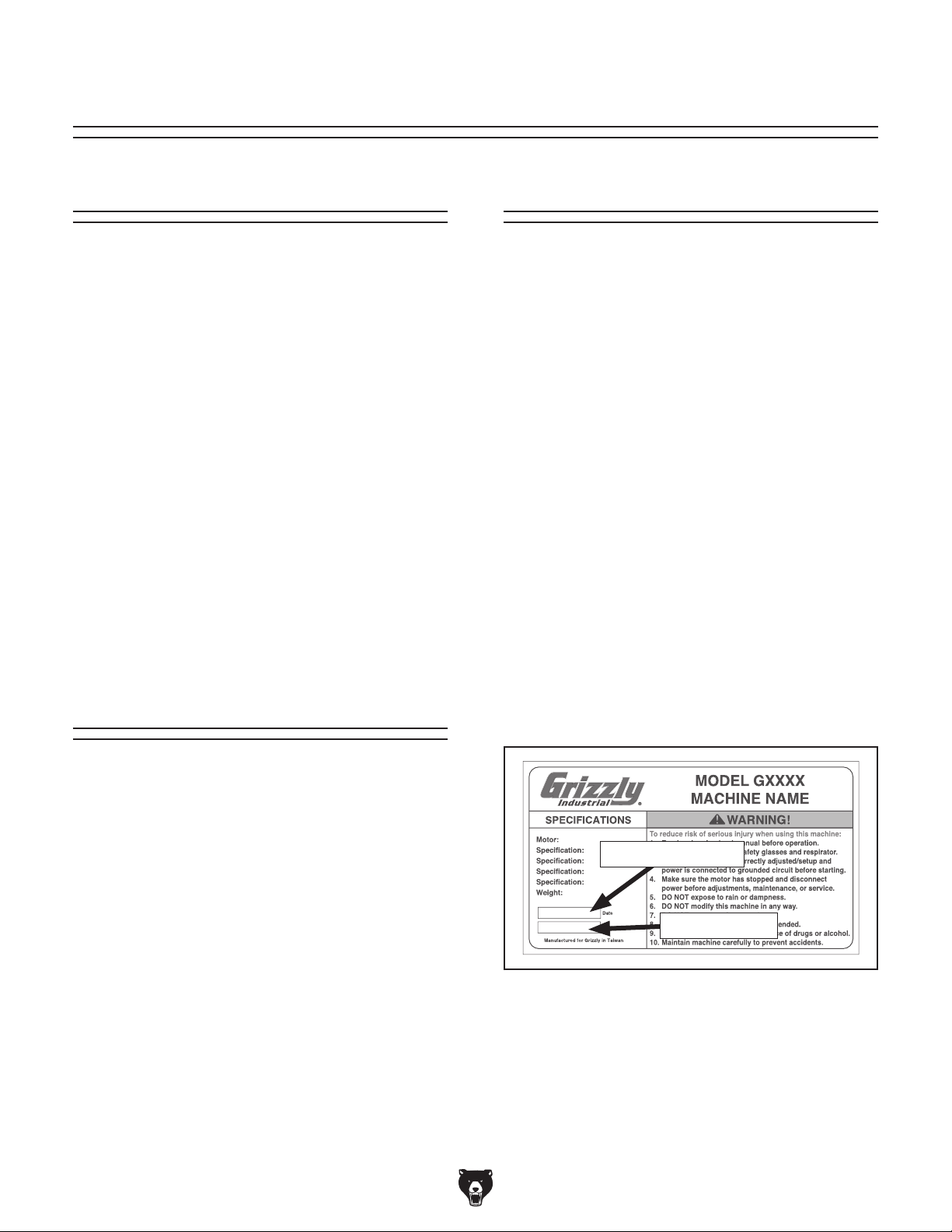
for help. Before calling, please write down the
Manufacture Date
stamped
into the machine ID label (see below). This information helps us determine if updated documentation is available for your machine.
We stand behind our machines. If you have
any questions or need help, use the information
below to contact us. Before contacting, please get
the serial number and manufacture date of your
machine. This will help us help you faster.
We want your feedback on this manual. What did
you like about it? Where could it be improved?
Please take a few minutes to give us feedback.
Machine Description
This 6 x 18" Surface Grinder allows you to resurface metal workpieces to create high-tolerance
flat surfaces. It utilizes a table that moves horizontally and a grinding wheel that moves vertically. By
mounting a workpiece to the table, then moving
the table and the grinding wheel during the grinding process, extremely small amounts of material
can be removed with each pass.
The G0763 is equipped with X- and Y-axis power
feeds that provide automated operation. In addition to the convenient front-mounted controls
and handwheels, the G0763 includes a magnetic
chuck, recycling flood coolant system, halogen
work light, and one-shot oiler for lubrication of
sliding parts.
For grinding wheel maintenance, the G0763
includes a wheel-balancing tool and a diamond
dresser.
Contact Info
Grizzly Technical Support
1203 Lycoming Mall Circle
Muncy, PA 17756
Phone: (570) 546-9663
Email: techsupport@grizzly.com
Manual Accuracy
made every effort to be exact with the
our policy of continuous improvement
sometimes the machine
.
, check our website
e post current
manual updates for free on our website at
.
and Serial Number
Manufacture Date
Serial Number
-2-
Grizzly Documentation Manager
P.O. Box 2069
Bellingham, WA 98227-2069
Email: manuals@grizzly.com
Model G0763 (Mfg. Since 8/13)
Page 5
To reduce your risk of
serious injury, read this
entire manual BEFORE
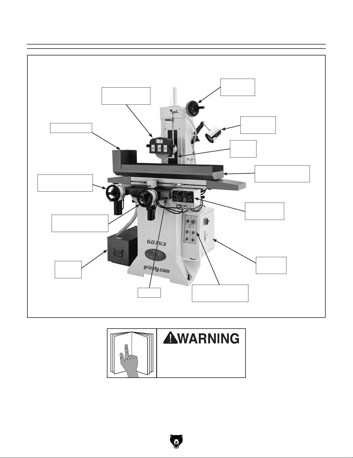
Splash Guard
X-Axis Handwheel
w/Power Feed
Identification
Grinding Wheel
& Wheel Guard
Z-Axis
Handwheel
Halogen
Work Light
Coolant
Nozzle
Work Table
w/Magnetic Chuck
Y-Axis Handwheel
w/Power Feed
Coolant
Tank
Saddle
Power Feed
Controls
Electrical
Cabinet
Grinding Wheel
& Coolant Controls
using machine.
Model G0763 (Mfg. Since 8/13)
-3-
Page 6
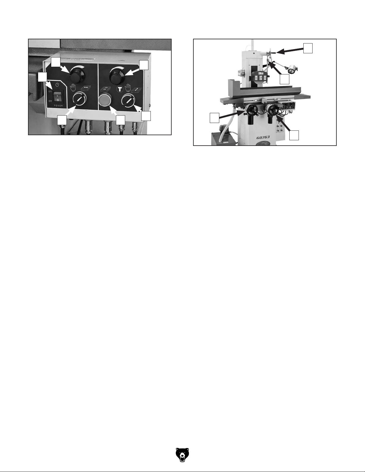
Basic Controls
Grinding Wheel & Coolant Controls
Refer to Figures 1–4 and the following descrip-
tions to develop an understanding of the basic
controls used to operate the surface grinder. This
knowledge will be necessary to safely complete
the Test Run later in this manual.
Additional details for certain controls are also
located in the Operations section.
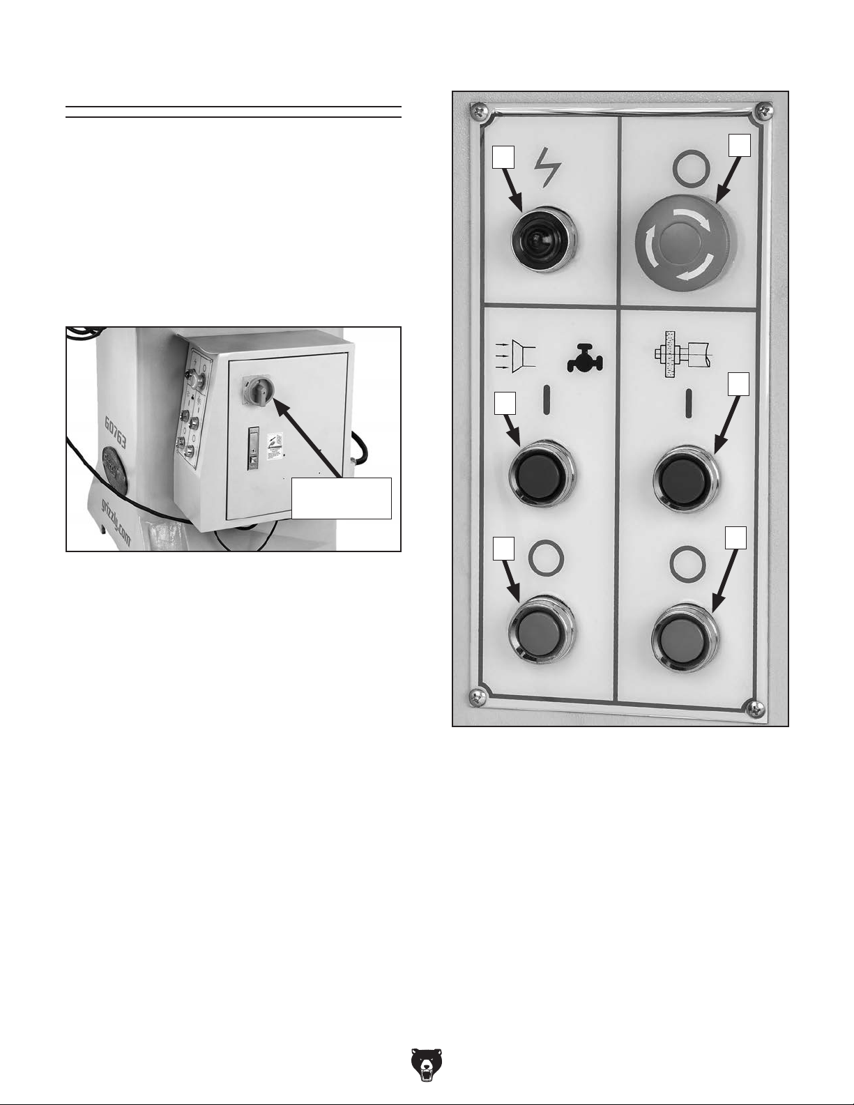
Master Power Switch
Master
Power Switch
Figure 1. Location of master power switch.
A
B
C
F
E
D
Master Power Switch: Enables power to flow to
the machine when the “l” is visible through the
switch.
Figure 2. Grinding wheel and coolant controls.
A. Power Lamp: Lights when power is flowing
to the machine.
B. Coolant Pump ON Button
C. Coolant Pump OFF Button
D. Grinding Motor OFF Button
E. Grinding Motor ON Button
F. Emergency STOP Button: Disables power
to grinding wheel motor and coolant pump.
To reset, twist the button clockwise until it
pops out.
-4-
Model G0763 (Mfg. Since 8/13)
Page 7
Power Feed Controls
Handwheels
P
H
G
L K
Figure 3. Power feed controls.
Refer to Power Feeds on Page 31 for detailed
instructions on operating the power feeds.
G. ON/OFF Switch: Enables power to the power
feed unit.
H. X-Axis Speed Control Knob: Controls the
speed of table movement along the X-axis.
I. Y-Axis Speed Control Knob: Controls the
speed of table movement along the Y-axis.
I
J
O
M
N
Figure 4. Handwheel controls.
M. X-Axis Handwheel: Manually controls X-axis
table movement.
N. Y-Axis Handwheel: Manually controls Y-axis
table movement. The graduated dial has
0.0005" increments with one full revolution
equaling 0.1000" of table travel.
O. Coolant Valve: Controls the flow of coolant
when coolant pump is turned ON.
J. Y-Axis Mode Selector Switch: Selects the
mode of operation for the Y-axis—jog (the
“T”), manual (the “hand”), or automatic (the
“table” symbol).
K. Y-Axis Reverse Button: Reverses the direc-
tion of Y-axis table movement.
L. X-Axis Mode Selector Switch: Selects the
mode of operation for the X-axis—manual
(the “hand”) or automatic (the “table” symbol).
P. Z-Axis Handwheel: Manually controls Z-axis
grinding wheel movement. The graduated
dial has 0.0002" increments with one full
revolution equaling 0.0500" of table travel.
Model G0763 (Mfg. Since 8/13)
-5-
Page 8

Machine Data Sheet
MACHINE DATA
SHEET
Customer Service #: (570) 546-9663 · To Order Call: (800) 523-4777 · Fax #: (800) 438-5901
MODEL G0763 6" X 18" SURFACE GRINDER WITH 2-AXIS
TABLE POWER FEED
Product Dimensions:
Weight............................................................................................................................................................ 1323 lbs.
Width (side-to-side) x Depth (front-to-back) x Height............................................................... 54-3/4 x 42 x 73-1/2 in.
Footprint (Length x Width)............................................................................................................................ 27 x 24 in.
Shipping Dimensions:
Type.................................................................................................................................................................... Wood
Content........................................................................................................................................................... Machine
Weight............................................................................................................................................................ 1544 lbs.
Length x Width x Height....................................................................................................................... 46 x 39 x 77 in.
Must Ship Upright................................................................................................................................................... Yes
Electrical:
Power Requirement........................................................................................................... 220V, Single-Phase, 60 Hz
Full-Load Current Rating....................................................................................................................................... 6.6A
Minimum Circuit Size.............................................................................................................................................. 15A
Connection Type....................................................................................................................................... Cord & Plug
Power Cord Included............................................................................................................................................... No
Recommended Power Cord............................................................................... “S”-Type, 3-Wire, 14 AWG, 300 VAC
Plug Included........................................................................................................................................................... No
Recommended Plug Type..................................................................................................................................... 6-15
Motors:
Coolant Pump
Main
Type........................................................................................................................................... TEFC Induction
Horsepower............................................................................................................................................. 1/8 HP
Phase............................................................................................................................................ Single-Phase
Amps........................................................................................................................................................... 0.6A
Speed................................................................................................................................................ 3450 RPM
Power Transfer ............................................................................................................................... Direct Drive
Bearings........................................................................................................... Shielded & Permanently Sealed
Type........................................................................................................................................... TEFC Induction
Horsepower.......................................................................................................................................... 1-1/2 HP
Phase............................................................................................................................................ Single-Phase
Amps.............................................................................................................................................................. 6A
Speed................................................................................................................................................ 3450 RPM
Power Transfer ............................................................................................................................... Direct Drive
Bearings........................................................................................................... Shielded & Permanently Sealed
-6-
Model G0763 (Mfg. Since 8/13)
Page 9

Main Specifications:
Operation Info
Max. Dist Wheel To Table................................................................................................................... 10-3/4 in.
Max. Distance Table To Spindle Center.............................................................................................. 14-1/4 in.
Longitudinal Travel.................................................................................................................................... 19 in.
Cross Travel.......................................................................................................................................... 7-1/8 in.
Spindle Dia.................................................................................................................................................. 1 in.
Spindle Speed................................................................................................................................... 3450 RPM
Max. Grinding Length.......................................................................................................................... 17-3/4 in.
Max. Grinding Width.................................................................................................................................... 6 in.
Grinding Wheel Bore............................................................................................................................. 1-1/4 in.
Grinding Wheel Diameter............................................................................................................................ 7 in.
Grinding Wheel Width............................................................................................................................... 1/2 in.
Vertical Handwheel Graduation.......................................................................................................... 0.0002 in.
Vertical Handwheel Revolution............................................................................................................... 0.05 in.
Crossfeed Handwheel Graduation...................................................................................................... 0.0005 in.
Crossfeed Handwheel Revolution............................................................................................................ 0.1 in.
Table Info
Table Size Length................................................................................................................................ 17-3/4 in.
Table Size Width.......................................................................................................................................... 6 in.
Floor To Table Height.......................................................................................................................... 39-3/8 in.
T Slot Size Width...................................................................................................................................... 1/2 in.
T Slot Size Height........................................................................................................................................ 1 in.
Stud Size.................................................................................................................................................. 3/8 in.
Head Size................................................................................................................................................. 7/8 in.
Magnetic Chuck Info
Magnetic Chuck Size Length............................................................................................................... 17-3/4 in.
Magnetic Chuck Size Width......................................................................................................................... 6 in.
Construction
Table.................................................................................................................................................... Cast Iron
Body..................................................................................................................................................... Cast Iron
Base..................................................................................................................................................... Cast Iron
Paint.......................................................................................................................................... Powder-Coated
Other
Column Diameter................................................................................................................................. 13-3/4 in.
Column Size Width.............................................................................................................................. 11-3/4 in.
Column Size Length............................................................................................................................ 34-1/4 in.
Coolant Tank Width................................................................................................................................... 11 in.
Coolant Tank Length........................................................................................................................... 19-3/4 in.
Coolant Tank Height............................................................................................................................ 11-3/4 in.
Coolant Tank Capacity.................................................................................................................. 9-1/4 Gallons
Other Specifications:
Country Of Origin ............................................................................................................................................... China
Warranty ........................................................................................................................................................... 1 Year
Approximate Assembly & Setup Time .............................................................................................................. 1 Hour
Serial Number Location ................................................................................................................... Machine ID Label
Sound Rating ..................................................................................................................................................... 65 dB
ISO 9001 Factory .................................................................................................................................................. Yes
CSA Certified .......................................................................................................................................................... No
Model G0763 (Mfg. Since 8/13)
-7-
Page 10

SECTION 1: SAFETY
For Your Own Safety, Read Instruction
Manual Before Operating This Machine
The purpose of safety symbols is to attract your attention to possible hazardous conditions.
This manual uses a series of symbols and signal words intended to convey the level of importance of the safety messages. The progression of symbols is described below. Remember that
safety messages by themselves do not eliminate danger and are not a substitute for proper
accident prevention measures. Always use common sense and good judgment.
Indicates an imminently hazardous situation which, if not avoided,
WILL result in death or serious injury.
Indicates a potentially hazardous situation which, if not avoided,
COULD result in death or serious injury.
Indicates a potentially hazardous situation which, if not avoided,
MAY result in minor or moderate injury. It may also be used to alert
against unsafe practices.
This symbol is used to alert the user to useful information about
NOTICE
proper operation of the machine.
Safety Instructions for Machinery
OWNER’S MANUAL. Read and understand this
owner’s manual BEFORE using machine.
TRAINED OPERATORS ONLY. Untrained operators have a higher risk of being hurt or killed.
Only allow trained/supervised people to use this
machine. When machine is not being used, disconnect power, remove switch keys, or lock-out
machine to prevent unauthorized use—especially
around children. Make workshop kid proof!
DANGEROUS ENVIRONMENTS. Do not use
machinery in areas that are wet, cluttered, or have
poor lighting. Operating machinery in these areas
greatly increases the risk of accidents and injury.
MENTAL ALERTNESS REQUIRED. Full mental
alertness is required for safe operation of machinery. Never operate under the influence of drugs or
alcohol, when tired, or when distracted.
ELECTRICAL EQUIPMENT INJURY RISKS. You
can be shocked, burned, or killed by touching live
electrical components or improperly grounded
machinery. To reduce this risk, only allow qualified
service personnel to do electrical installation or
repair work, and always disconnect power before
accessing or exposing electrical equipment.
DISCONNECT POWER FIRST.
nect machine from power supply BEFORE making
adjustments, changing tooling, or servicing machine.
This prevents an injury risk from unintended startup
or contact with live electrical components.
EYE PROTECTION. Always wear ANSI-approved
safety glasses or a face shield when operating or
observing machinery to reduce the risk of eye
injury or blindness from flying particles. Everyday
eyeglasses are NOT approved safety glasses.
Always discon-
-8-
Model G0763 (Mfg. Since 8/13)
Page 11

WEARING PROPER APPAREL. Do not wear
clothing, apparel or jewelry that can become
entangled in moving parts. Always tie back or
cover long hair. Wear non-slip footwear to avoid
accidental slips, which could cause loss of workpiece control.
HAZARDOUS DUST. Dust created while using
machinery may cause cancer, birth defects, or
long-term respiratory damage. Be aware of dust
hazards associated with each workpiece material,
and always wear a NIOSH-approved respirator to
reduce your risk.
HEARING PROTECTION. Always wear hearing protection when operating or observing loud
machinery. Extended exposure to this noise
without hearing protection can cause permanent
hearing loss.
REMOVE ADJUSTING TOOLS. Tools left on
machinery can become dangerous projectiles
upon startup. Never leave chuck keys, wrenches,
or any other tools on machine. Always verify
removal before starting!
USE CORRECT TOOL FOR THE JOB. Only use
this tool for its intended purpose—do not force
it or an attachment to do a job for which it was
not designed. Never make unapproved modifications—modifying tool or using it differently than
intended may result in malfunction or mechanical
failure that can lead to personal injury or death!
AWKWARD POSITIONS. Keep proper footing
and balance at all times when operating machine.
Do not overreach! Avoid awkward hand positions
that make workpiece control difficult or increase
the risk of accidental injury.
CHILDREN & BYSTANDERS. Keep children and
bystanders at a safe distance from the work area.
Stop using machine if they become a distraction.
FORCING MACHINERY. Do not force machine.
It will do the job safer and better at the rate for
which it was designed.
NEVER STAND ON MACHINE. Serious injury
may occur if machine is tipped or if the cutting
tool is unintentionally contacted.
STABLE MACHINE. Unexpected movement during operation greatly increases risk of injury or
loss of control. Before starting, verify machine is
stable and mobile base (if used) is locked.
USE RECOMMENDED ACCESSORIES. Consult
this owner’s manual or the manufacturer for recommended accessories. Using improper accessories will increase the risk of serious injury.
UNATTENDED OPERATION. To reduce the
risk of accidental injury, turn machine OFF and
ensure all moving parts completely stop before
walking away. Never leave machine running
while unattended.
MAINTAIN WITH CARE. Follow all maintenance
instructions and lubrication schedules to keep
machine in good working condition. A machine
that is improperly maintained could malfunction,
leading to serious personal injury or death.
CHECK DAMAGED PARTS. Regularly inspect
machine for any condition that may affect safe
operation. Immediately repair or replace damaged
or mis-adjusted parts before operating machine.
MAINTAIN POWER CORDS. When disconnecting cord-connected machines from power, grab
and pull the plug—NOT the cord. Pulling the cord
may damage the wires inside. Do not handle
cord/plug with wet hands. Avoid cord damage by
keeping it away from heated surfaces, high traffic
areas, harsh chemicals, and wet/damp locations.
GUARDS & COVERS. Guards and covers reduce
accidental contact with moving parts or flying
debris. Make sure they are properly installed,
undamaged, and working correctly.
Model G0763 (Mfg. Since 8/13)
EXPERIENCING DIFFICULTIES. If at any time
you experience difficulties performing the intended operation, stop using the machine! Contact our
Technical Support at (570) 546-9663.
-9-
Page 12

Additional Safety for Surface Grinders
WHEEL SPEED RATING. Wheels operated at a
faster speed than rated for may break or fly apart.
Before mounting a new wheel, be sure the wheel
RPM rating is equal or higher than the speed of
the grinder.
WHEEL FLANGES. Only use the flanges included
with the grinder when mounting wheels. Other
flanges may not properly secure the wheel and
could cause the wheel to fly off or break apart.
RING T EST. Perform a "ring test" on grinding
wheels before installation to ensure that they are
safe to use. A wheel that does not pass the ring
test may break or fly apart during operation.
STARTING GRINDER. If a wheel IS damaged, it
will usually fly apart shortly after start-up. To protect yourself, always stand away from the grinding
wheel when turning the machine ON and allow the
wheel to gain full speed before standing in front of
it.
CRACKED WHEEL. Cracked wheels may break
and fly apart during operation. Replace cracked
wheels immediately!
PROTECTIVE CLOTHING. Protect skin from flying sparks by wearing close-fitting long sleeves
and buttoned-up shirt. In case of falling heavy
objects, wear leather, non-skid boots with added
toe protection.
GRINDING MAGNESIUM. Grinding material with
magnesium content may increase the risk of fire
or explosion. Before grinding material with magnesium content, review all available safety information that pertains to grinding magnesium, including
the National Fire Protection Association standard
NFPA 480, “Storage, Handling and Processing
Magnesium.”
WORKPIECE CONTACT. A heavy impact
against the grinding wheel can cause it to break
or fly apart, causing serious personal injuries.
Avoid jamming the workpiece into the wheel to
reduce this risk.
LUNG PROTECTION. Grinding produces hazardous dust, which may cause long-term respiratory problems if breathed. Always wear a NIOSH
approved dust mask or respirator when grinding,
and use coolant when possible to minimize this
risk.
HAND/WHEEL CONTACT. Grinding wheels
have the capability of removing a lot of skin fast.
Make sure the workpiece is securely clamped to
the table, then position your hands a safe distance away when grinding. Avoid wearing gloves
as they may get caught in the grinding wheel and
cause even more serious entanglement injuries.
DUST COLLECTION. DO NOT connect a surface grinder to a dust collection system that is
used with woodworking machines. Sparks emitted from the grinding process may ignite wood
particles, resulting in fire or explosion. Only use
a metal-specific dust collection system with this
machine.
COOLANT USAGE. Use the correct personal
protection equipment when handling coolant.
Follow federal, state, and fluid manufacturer
requirements for proper disposal.
EYE PROTECTION. Grinding causes small particles to become airborne at a high rate of speed.
ALWAYS wear ANSI-approved eye and face protection when using this machine.
-10 -
Model G0763 (Mfg. Since 8/13)
Page 13

SECTION 2: POWER SUPPLY
Before installing the machine, consider the availability and proximity of the required power supply
circuit. If an existing circuit does not meet the
requirements for this machine, a new circuit must
be installed. To minimize the risk of electrocution,
fire, or equipment damage, installation work and
electrical wiring must be done by an electrican or
qualified service personnel in accordance with all
applicable codes and standards.
Electrocution, fire, or
equipment damage may
occur if machine is not
correctly grounded and
connected to the power
The full-load current rating is the amperage a
machine draws at 100% of the rated output power.
On machines with multiple motors, this is the
amperage drawn by the largest motor or sum of all
motors and electrical devices that might operate
at one time during normal operations.
The full-load current is not the maximum amount
of amps that the machine will draw. If the machine
is overloaded, it will draw additional amps beyond
the full-load rating.
If the machine is overloaded for a sufficient length
of time, damage, overheating, or fire may result—
especially if connected to an undersized circuit.
To reduce the risk of these hazards, avoid overloading the machine during operation and make
sure it is connected to a power supply circuit that
meets the requirements in the following section.
This machine is prewired to operate on a 220V
power supply circuit that has a verified ground and
meets the following requirements:
For your own safety and protection of
Note: The circuit requirements listed in this manual apply to a dedicated circuit—where only one
machine will be running at a time. If this machine
will be connected to a shared circuit where multiple machines will be running at the same time,
consult a qualified electrician to ensure that the
circuit is properly sized for safe operation.
A power supply circuit includes all electrical
equipment between the breaker box or fuse panel
in the building and the machine. The power supply circuit used for this machine must be sized to
safely handle the full-load current drawn from the
machine for an extended period of time. (If this
machine is connected to a circuit protected by
fuses, use a time delay fuse marked D.)
Availability
supply.
Full-Load Current Rating
Circuit Requirements for 220V
Nominal Voltage .........208V, 220V, 230V, 240V
Cycle ..........................................................60 Hz
Phase .................................................... 1-Phase
Power Supply Circuit ......................... 15 Amps
Plug/Receptacle ............................. NEMA 6-15
Cord ........“ S ”-Ty p e, 3-Wire, 14 AWG, 300 VAC
Full-Load Current Rating at 220V .... 6.6 Amps
Model G0763 (Mfg. Since 8/13)
property, consult an electrician if you are
unsure about wiring practices or electrical
codes in your area.
-11-
Page 14
We do not recommend using an extension cord
with this machine.
cord, only use it if absolutely necessary and only
on a temporary basis.
Extension cords cause voltage drop, which may
damage electrical components and shorten motor
life. Voltage drop increases as the extension cord
size gets longer and the gauge size gets smaller
(higher gauge numbers indicate smaller sizes).
Any extension cord used with this machine must
contain a ground wire, match the required plug
and receptacle, and meet the following requirements:
Grounding Instructions
This machine MUST be grounded. In the event
of certain malfunctions or breakdowns, grounding
reduces the risk of electric shock by providing a
path of least resistance for electric current.
Improper connection of the equipment-grounding
wire can result in a risk of electric shock. The
wire with green insulation (with or without yellow
stripes) is the equipment-grounding wire. If repair
or replacement of the power cord or plug is necessary, do not connect the equipment-grounding
wire to a live (current carrying) terminal.
Check with a qualified electrician or service personnel if you do not understand these grounding
requirements, or if you are in doubt about whether
the tool is properly grounded. If you ever notice
that a cord or plug is damaged or worn, disconnect it from power, and immediately replace it with
a new one.
Serious injury could occur if you connect
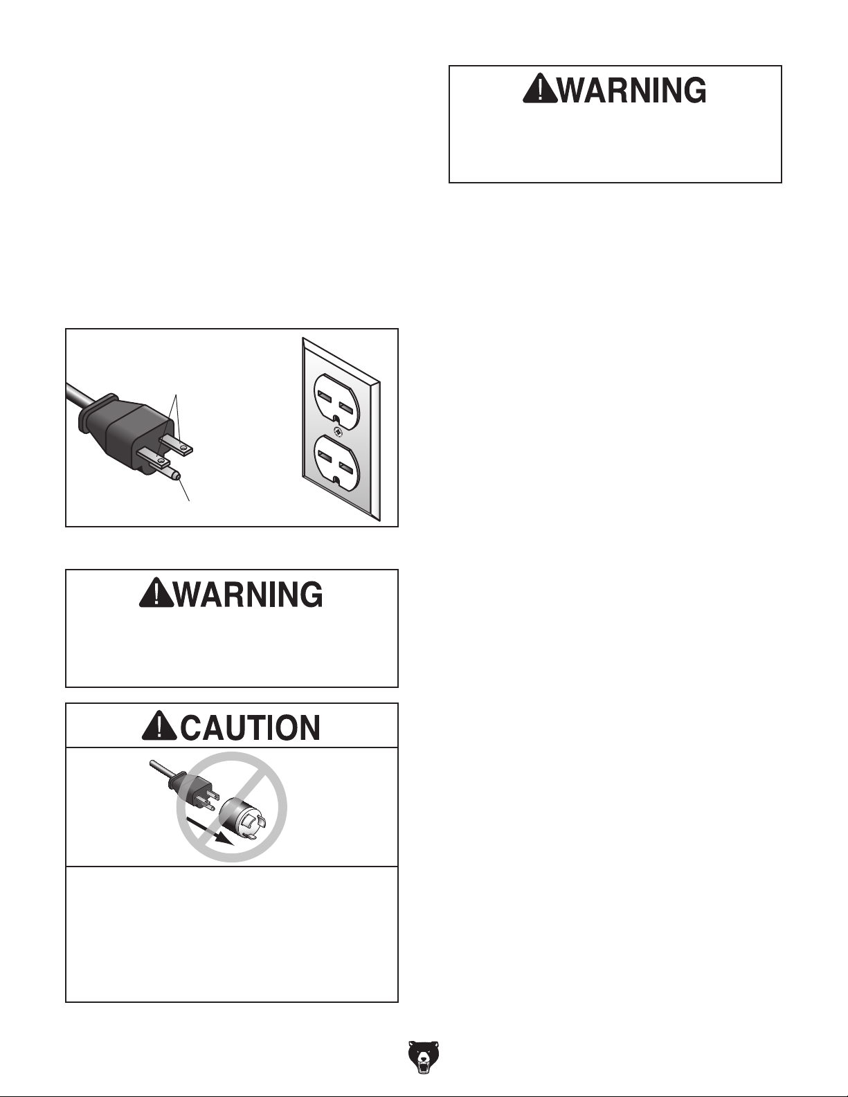
The power cord and plug specified under “Circuit
Requirements for 220V”
has an equipment-grounding wire and a grounding prong. The plug must only be inserted into
a matching receptacle (outlet) that is properly
installed and grounded in accordance with all
local codes and ordinances (see figure below).
No adapter should be used with the
required plug. If the plug does not fit the
available receptacle, or the machine must
on the previous page
GROUNDED
6-15 RECEPTACLE
Current Carrying Prongs
6-15 PLUG
Serious injury could occur if you connect
the machine to power before completing the
setup process. DO NOT connect to power
until instructed later in this manual.
Grounding Prong
Figure 5. Typical 6-15 plug and receptacle.
the machine to power before completing the
setup process. DO NOT connect to power
until instructed later in this manual.
be reconnected for use on a different type
of circuit, the reconnection must be made
by a qualified electrician and comply with all
local codes and ordinances.
-12-
Extension Cords
If you must use an extension
Minimum Gauge Size ...........................14 AWG
Maximum Length (Shorter is Better).......50 ft.
Model G0763 (Mfg. Since 8/13)
Page 15
SECTION 3: SETUP
Your machine was carefully packaged for safe
transportation. Remove the packaging materials
from around your machine and inspect it. If you
discover any damage, please call us immediately
at (570) 546-9663
Save the containers and all packing materials for
possible inspection by the carrier or its agent.
Otherwise, filing a freight claim can be difficult.
When you are completely satisfied with the condition of your shipment, inventory the contents.
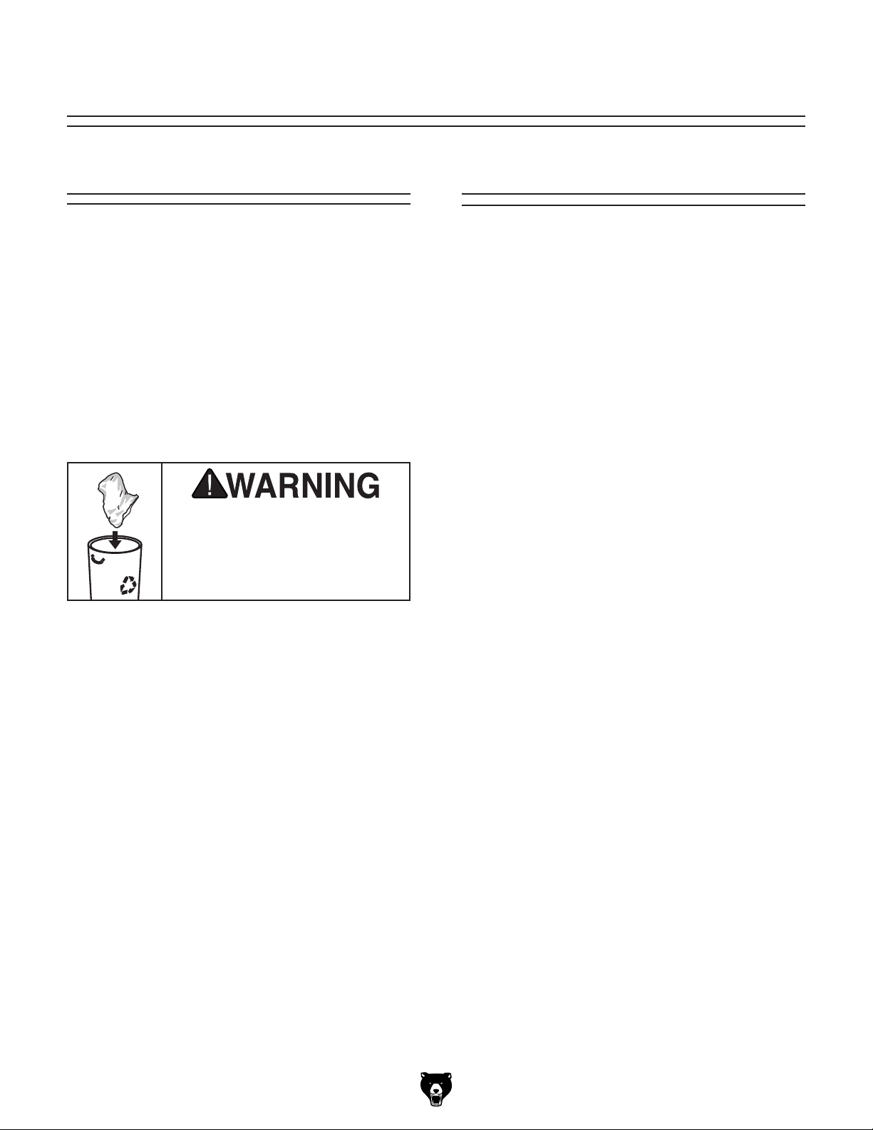
Keep children and pets away
from plastic bags or packing
materials shipped with this
Unpacking
for advice.
SUFFOCATION HAZARD!
Needed for Setup
The following are needed to complete the setup
process, but are not included with your machine.
Description Qty
• Additional People ....................................... 1
• Safety Glasses .................1 Pair Per Person
• Cleaner/Degreaser (Page 15) .... As Needed
• Disposable Shop Rags ............... As Needed
• Forklift (rated for at least 2500 lbs.) ............ 1
• Safety Hooks & Chains
(rated for at least 2500 lbs. each) ............... 4
• Precision Level ........................................... 1
• NLGI#2 Grease* ......................... As Needed
• Coolant ........................ Approximately 8 Gal.
• ISO 32 Oil* .................. Approximately 1 Pint
* See Page 34 for offerings from Grizzly.
machine. Discard immediately.
Model G0763 (Mfg. Since 8/13)
-13-
Page 16
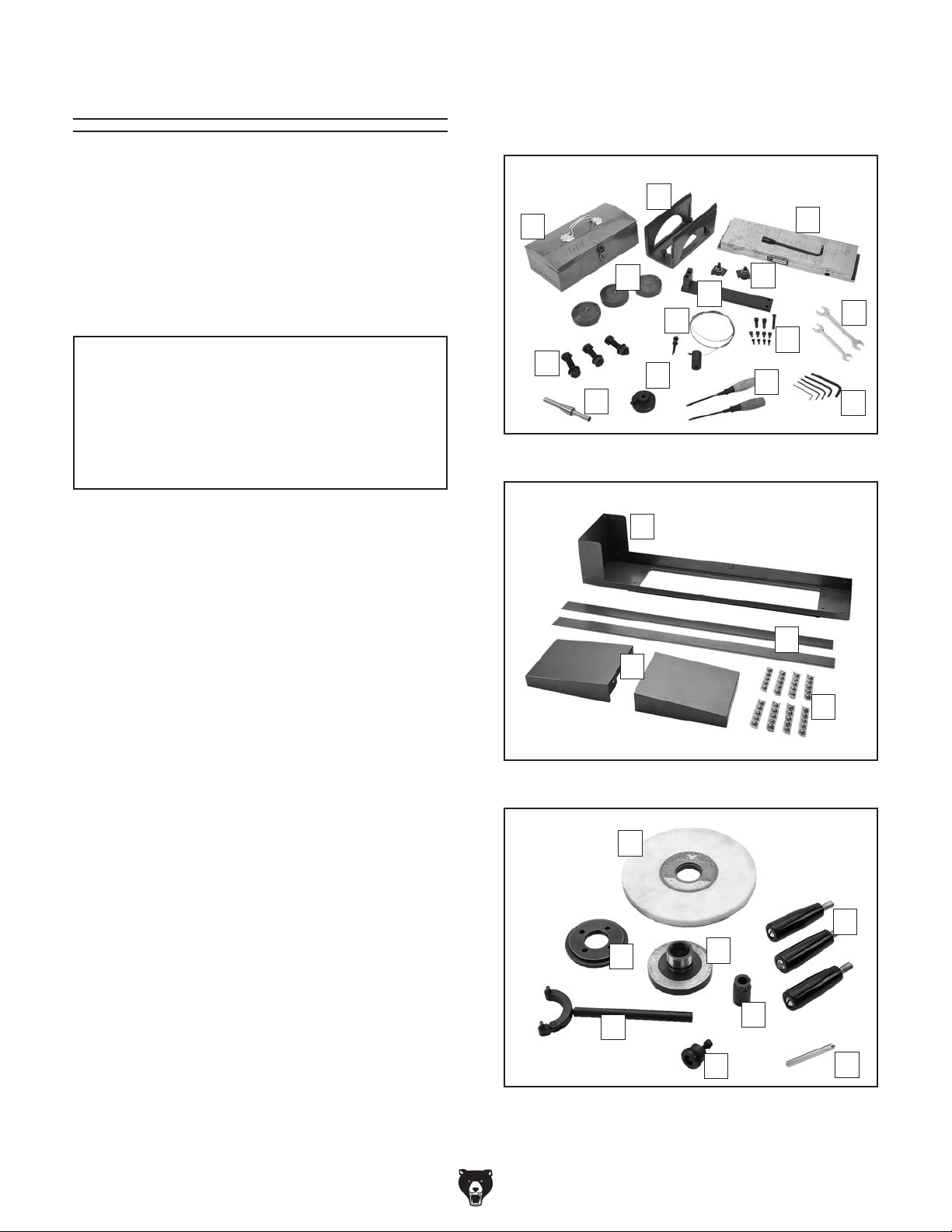
Inventory
The following is a list of items shipped with your
machine. Before beginning setup, lay these items
out and inventory them.
If any non-proprietary parts are missing (e.g. a
nut or a washer), we will gladly replace them; or
for the sake of expediency, replacements can be
obtained at your local hardware store.
X. Wheel Flange Wrench ................................ 1
Y. Wheel Puller ............................................... 1
Z. Diamond Dresser ....................................... 1
B
A
C
NOTICE
If you cannot find an item on this list, carefully check around/inside the machine and
packaging materials. Often, these items get
lost in packaging materials while unpacking or they are pre-installed at the factory.
Inventory (Figures 6–8) Qty
A. Toolbox ....................................................... 1
B. Wheel Balancing Base ............................... 1
C. Magnetic Chuck w/Key ............................... 1
D. Magnetic Chuck Clamp Assemblies
—Rubber Pads ........................................... 2
—Cap Screws M10-1.5 x 55 ....................... 2
—T-nuts M -10-1.5 ....................................... 2
E. Table Cable Bracket ................................... 1
F. Leveling Pads ............................................. 3
G. Leveling Pad Bolts M20-2.5 x 80
w/Hex Nuts & Flat Washers ....................... 3
H. Table Cable Assembly ................................ 1
I. Fasteners for Table
— Cap Screw M10-1.5 x 50 ......................... 1
— Cap Screws M10-1.5 x 25 ....................... 2
— Cap Screws M8-1.25 x 12 ....................... 4
— Cap Screws M6-1 x 12 ........................... 4
J. Wrenches 19 x 22mm, 14 x 17mm ....1 Each
K. Hex Wrenches 8, 6, 5, 4, 3mm .........1 Each
L. Screwdrivers, Flat & Phillips ..............1 Each
M. Diamond Dresser Base .............................. 1
N. Wheel Balancing Arbor .............................. 1
O. Splash Guard Base .................................... 1
P. Splash Guard Sides ................................... 2
Q. Table Ends ................................................. 2
R. Table Ball Bearing Segments ..................... 8
S. Grinding Wheel 7"D x
T. Handwheel Handles ................................... 3
U. Arbor Nut .................................................... 1
V. Wheel Sleeve ............................................. 1
W. Wheel Flange ............................................. 1
-14-
1
⁄2 "T x 1 1⁄4" 80-Grit . . 1
F
E
H
G
N
Figure 6. Small parts inventory.
Figure 7. Small parts inventory.
Figure 8. Small parts inventory.
M
O
Q
S
W
X
Model G0763 (Mfg. Since 8/13)
V
Y
D
J
I
L
K
P
R
T
U
Z
Page 17
The unpainted surfaces of your machine are
coated with a heavy-duty rust preventative that
prevents corrosion during shipment and storage.
This rust preventative works extremely well, but it
will take a little time to clean.
Be patient and do a thorough job cleaning your
machine. The time you spend doing this now will
give you a better appreciation for the proper care
of your machine's unpainted surfaces.
There are many ways to remove this rust preventative, but the following steps work well in a wide
variety of situations. Always follow the manufacturer’s instructions with any cleaning product you
use and make sure you work in a well-ventilated
area to minimize exposure to toxic fumes.
Before cleaning, gather the following:
• Disposable rags
• Cleaner/degreaser (WD•40 works well)
• Safety glasses & disposable gloves
• Plastic paint scraper (optional)
Basic steps for removing rust preventative:
1.
2.
3.
4.
Many cleaning solvents
work in a well-ventilated
Avoid chlorine-based solvents, such as
Cleanup
Gasoline and petroleum
products have low flash
points and can explode
or cause fire if used to
clean machinery. Avo i d
using these products
to clean machinery.
Put on safety glasses.
Coat the rust preventative with a liberal
amount of cleaner/degreaser, then let it soak
for 5–10 minutes.
Wipe off the surfaces. If your cleaner/degreas-
er is effective, the rust preventative will wipe
off easily. If you have a plastic paint scraper,
scrape off as much as you can first, then wipe
off the rest with the rag.
are toxic if inhaled. Only
area.
NOTICE
acetone or brake parts cleaner, that may
damage painted surfaces.
T23692—Orange Power Degreaser
A great product for removing the waxy shipping
grease from your machine during clean up.
Figure 9. T23692 Orange Power Degreaser.
Repeat Steps 2–3 as necessary until clean,
then coat all unpainted surfaces with a quality
metal protectant to prevent rust.
Model G0763 (Mfg. Since 8/13)
-15-
Page 18
Site Considerations
Weight Load
Physical Environment
Place this machine near an existing power source.
Shadows, glare, or strobe effects that may distract
Refer to the Machine Data Sheet for the weight
of your machine. Make sure that the surface upon
which the machine is placed will bear the weight
of the machine, additional equipment that may be
installed on the machine, and the heaviest workpiece that will be used. Additionally, consider the
weight of the operator and any dynamic loading
that may occur when operating the machine.
Space Allocation
Consider the largest size of workpiece that will
be processed through this machine and provide
enough space around the machine for adequate
operator material handling or the installation of
auxiliary equipment. With permanent installations,
leave enough space around the machine to open
or remove doors/covers as required by the maintenance and service described in this manual.
See below for required space allocation.
Children or untrained people
may be seriously injured by
this machine. Only install in an
access restricted location.
The physical environment where the machine is
operated is important for safe operation and longevity of machine components. For best results,
operate this machine in a dry environment that is
free from excessive moisture, hazardous chemicals, airborne abrasives, or extreme conditions.
Extreme conditions for this type of machinery are
generally those where the ambient temperature
range exceeds 41°–104°F; the relative humidity
range exceeds 20–95% (non-condensing); or the
environment is subject to vibration, shocks, or
bumps.
Electrical Installation
Make sure all power cords are protected from
traffic, material handling, moisture, chemicals,
or other hazards. Make sure to leave access to
a means of disconnecting the power source or
engaging a lockout/tagout device, if required.
Lighting
Lighting around the machine must be adequate
enough that operations can be performed safely.
or impede the operator must be eliminated.
-16 -
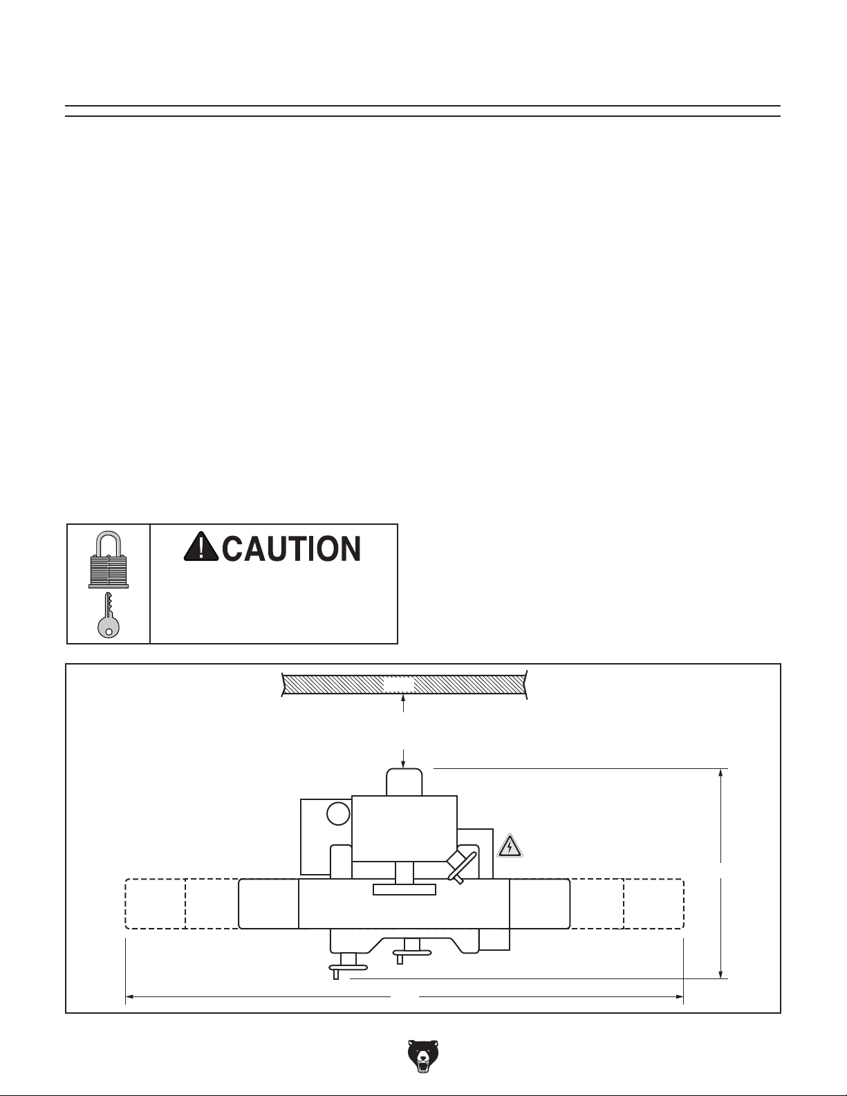
Wall
Wall
30" Minimum
Clearance
79"
Figure 10. Minimum working clearances.
46"
Model G0763 (Mfg. Since 8/13)
Page 19

Lifting & Placing
get help from other people
HEAVY LIF T!
Straining or crushing injury
may occur from improperly
lifting machine or some of
its parts. To reduce this risk,
5. Disconnect coolant hose from stand pipe
shown in Figure 12.
Coolant Hose
Connection
and use a fork lift (or other
lifting equipment) rated for
weight of this machine.
Lifting and placing the G0763 will require help
from at least one other person, a fork lift with
four safety hooks and chains (rated for 2500 lbs.
each), and a precision level.
To lift and place the machine:
1. Remove top crate from shipping pallet.
2. Remove loosely packed items from shipping
pallet.
3. Move pallet and machine to selected position.
4. Disconnect coolant power cable from electrical cabinet (see Figure 11) by twisting the
knurled ring counterclockwise (the ring closest to the electrical cabinet).
Stand
Pipe
Figure 12. Coolant hose connection to stand
pipe.
6. Set coolant tank assembly aside.
7. Attach a handle to Y-axis handwheel, then
move saddle as close to column as possible.
8. Unbolt machine from shipping pallet.
9. Secure a safety hook and chain to each of
four lifting studs (see Figure 13 for identification).
Note: Place padding between chains and
machine to prevent scratching machine.
Coolant Pump
Electrical Connection
Figure 11. Location of coolant pump electrical
connection to electrical cabinet.
Model G0763 (Mfg. Since 8/13)
Lifting Studs
(2 of 4)
Figure 13. Lifting studs (2 of 4 shown).
-17-
Page 20
10. With help from another person to steady the
load, lift machine enough to remove pallet.
Assembly
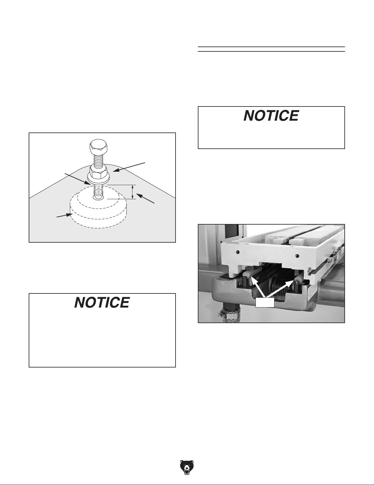
11. With machine still suspended above floor,
thread leveling pad bolts, as illustrated in
Figure 14, into holes used to bolt machine to
pallet.
Note: Make sure flat washer and hex nut
are above machine base and bottom of bolt
extends approximately
base.
Threaded
Hole
Leveling
Pad
3
⁄4" below machine
Flat Washer
& Nut Above
Machine Base
Approx.
3
⁄4"
To assemble the surface grinder:
1. Install handles on X- and Z-axis handwheels.
2. Remove table restraints.
Take care not to damage table or saddle
ways. Any damage to these surfaces will be
permanent and result in poor finishes.
3. With help from another person, remove table
and place it upside down on a clean, flat surface.
4. Store plastic shipping rods (see Figure 15) for
future use when storing or moving machine to
protect ways.
Figure 14. Leveling pad and bolt installed.
12. Position leveling pads underneath bolts and
lower machine so the bolts rest in center of
pads.
For accurate results and to prevent warping
the cast iron ways, the table MUST be level
from side to side and from front to back.
Recheck the ways 24 hours after installation,
two weeks after that, and then annually to
make sure they remain level.
13. Using a precision level on unpainted table
surface without magnetic chuck, adjust leveling pad bolts until table is level from side to
side and front to back.
14. When table is properly leveled, tighten down
hex nuts on bolts to secure settings.
Rods
Figure 15. Plastic rods used for shipping or
storage purposes.
5. Clean the table and saddle ways, and
table ball bearing segments, as directed on
Page 15.
15. Reconnect coolant pump electrical cord and
coolant hose.
-18-
Model G0763 (Mfg. Since 8/13)
Page 21

6. Assemble ball bearing segments into two
strips of equal size (four segments each).
7. Apply medium coat of NLGI#2 grease to ball
bearing strips.
Note: When cable is properly wrapped
around pulley in next step, have another
person maintain enough tension on cable so
that it stays in pulley grooves until it can be
secured in following steps.
8. Position ball bearing strips in middle of saddle ways, as shown in Figure 16.
Ball Bearing Strips
Figure 16. Ball bearing strips positioned on
saddle ways.
9. With the help of another person, gently place
table right side up on ball bearing strips.
10. Feed table cable under table so that attached
cable barrel is on the right of machine, as
shown in Figure 17.
12. Wrap cable around pulley twice, as shown in
Figures 18–19.
Note: Pay close attention to position and
orientation of cable on pulley, as illustrated in
Figure 18.
Open End
of Pulley
To the
Right End
To the
Left End
Figure 18. Cable orientation on pulley.
Open End
of Pulley
x 1
Cable Barrel
Figure 17. Cable barrel attached.
11. Secure barrel to table with (1) M10-1.5 x 50
cap screw.
Model G0763 (Mfg. Since 8/13)
Figure 19. Cable on pulley, as viewed from left
end of table.
13. While maintaining cable tension, move table
back and forth several times to ensure cable
position on pulley allows full travel of table.
— If the cable position on the pulley does not
allow full travel of table, reposition cable on
pulley until it does.
-19 -
Page 22

14. Secure table cable bracket underneath left
end of table with (2) M10-1.5 x 25 cap
screws, as shown in Figure 20.
17. Attach table ends to table with (4) M8-1.25 x 12
cap screws (see Figure 22).
Cable
Bracket
x 2
Figure 20. Cable bracket installed.
15. Thread hex bolt attached to end of cable into
cable bracket until cable tension is enough
to keep cable tightly wrapped around pulley
(see Figure 21).
2
of 4
Table
End
Figure 22. Table end attached.
18. Stone and clean any burrs from unpainted
table surface and bottom of magnetic chuck,
then apply a thin coat of ISO 32 oil to both
surfaces.
19. With help from another person, position
magnetic chuck in center of table with chuck
control facing to front, as shown in Figure 23.
Hex Bolt
Jam Nut
Figure 21. Cable attached to cable bracket.
16. Tighten jam nut against bracket to secure
position of hex bolt.
Chuck Control
Clamp Assemblies
Figure 23. Magnetic chuck attached to table.
20. Secure magnetic chuck to table with (2)
clamp assemblies, as shown in Figure 23.
-20-
Model G0763 (Mfg. Since 8/13)
Page 23

21. Position splash guard base on table with
high end to the left of machine, as shown in
Figure 24.
Splash Guard
High End
x 4
Power Connection
Before the machine can be connected to the
power source, an electrical circuit must be made
available that meets the minimum specifications
given in Circuit Requirements for 220V on
Page 11. If a power circuit has not been prepared
for the machine, do that now.
To ensure a safe and code-compliant setup, all
electrical work must be done by an electrician or
qualified service personnel.
To connect the power supply to the machine:
Figure 24. Splash guard base attached.
22. Secure splash guard base with (4) M6-1 x 12
cap screws, as shown in Figure 24.
23. Insert splash guard sides into slots on each
side of splash guard base, as shown in
Figure 25.
Splash Guard
Sides
1. Turn master power switch OFF (see
Figure 26), then press latch to open electri-
cal cabinet door.
Master
Power Switch
Figure 26. Location of master power switch.
Figure 25. Splash guard sides installed.
Model G0763 (Mfg. Since 8/13)
-21-
Page 24

setup instructions have been performed.
Operating an improperly setup machine
Serious injury or death can result from
2. Install a strain relief in available hole in bot-
tom of electrical cabinet, then pull incoming
power cord through strain relief.
Test Run
3. Connect incoming hot wires to bottom of first
two terminal bar connectors, then connect
incoming ground wire to grounding bar (refer
to the Electrical Cabinet Wiring Diagram
on Page 42 for additional details).
4. Leave slack in wires inside cabinet, tighten
strain relief to secure cord, then tug on power
cord outside electrical cabinet to make sure
wires do not move inside cabinet.
— If wires do move when you tug on power
cord outside electrical cabinet, disconnect
wires, reposition cord, then tighten strain
relief so that cord will not move when
tugged on. Reconnect wires as instructed
in Step 3.
5. Close electrical cabinet door, but leave master power switch OFF.
6. Attach a NEMA 6-15 plug to other end of
power cord per manufacturer's directions
(refer to Electrical Cabinet Wiring Diagram
on Page 42 for additional details).
Once assembly is complete, test run the machine
to ensure the following components are working
properly:
• Grinding motor
• Coolant pump
• Emergency STOP button
• Table power feed
If you find an unusual problem during the test run,
immediately stop the machine, disconnect it from
power, and fix the problem BEFORE operating the
machine again. The Troubleshooting table on
Page 39 can help.
using this machine BEFORE understanding
its controls and related safety information.
DO NOT operate, or allow others to operate,
machine until the information is understood.
7. Connect machine to power source by insert-
ing power cord plug into a matching receptacle.
DO NOT start machine until all preceding
may result in malfunction or unexpected results that can lead to serious injury,
death, or machine/property damage.
You MUST understand the function of the controls
to safely complete the Test Run. If you are not
sure how a control functions or where it is, refer to
Basic Controls beginning on Page 4.
To test run the machine:
1. Push Emergency STOP button in.
2. Remove all tools used for setup from the
machine.
3. Fill and operate the one-shot oiler (refer to
Lubrication on Page 36 for detailed instruc-
tions).
-22-
Model G0763 (Mfg. Since 8/13)
Page 25

4. Fill the coolant tank with coolant (refer to
Coolant System on Page 37 for detailed
instructions).
15. WITHOUT resetting the STOP button, press
the grinding motor ON button. Machine should
not start.
5. If grinding wheel is mounted, make sure it is
properly mounted and wheel guard is properly secured (refer to Mounting/Removing
Wheel on Page 28 for detailed instructions).
Note: If grinding wheel is not mounted, it is
not necessary to mount it to complete Test
Run.
6. Turn master power switch ON—control panel
power lamp should light.
7. Twist Emergency STOP button clockwise
until it pops out (see Figure 27)—this resets
button so machine can start.
—If the machine does start (with the
Emergency STOP button pushed in),
immediately disconnect power to the
machine. The Emergency STOP button
safety feature is not working correctly. This
safety feature must work properly before
proceeding with regular operations. Call
Tech Support for help.
16. Reset Emergency STOP button.
17. Rotate X- and Y-axis speed control knobs
on power feed unit all the way counterclockwise—this prevents unexpected table movement when power is enabled to unit.
18. Turn power feed unit ON.
19. Rotate X-axis mode selector switch to the
right (pointing at “table” symbol).
Note: In the next steps, keep your hand over
the speed control knobs so you can quickly
stop table movement if necessary.
Figure 27. Resetting the Emergency STOP
button.
8. Make sure grinding wheel and guard are
safely above magnetic chuck but low enough
for coolant to flow onto chuck in a later step
without excessive splashing.
9. Press grinding motor ON button. Grinding
motor should start.
10. Press grinding motor OFF button. Grinding
motor should stop.
11. Make sure coolant nozzle is positioned close
to table and pointing to the left, then open
coolant valve.
12. Press coolant pump ON button. Coolant
should flow from coolant nozzle.
13. Press coolant pump OFF button and close
coolant valve. Coolant flow should stop.
14. Press Emergency STOP button.
20. Slowly rotate X-axis speed control knob until
tables begins to move. Table should travel
side-to-side automatically.
21. Rotate Y-axis mode selector switch to the
right (pointing at “table” symbol).
22. Slowly rotate Y-axis speed control knob until
tables begins to move. Table should move
when table completes one X-axis side-to-side
cycle.
23. Rotate X- and Y-axis speed control knobs all
the way counterclockwise to stop table movement.
24. Rotate X- and Y-axis mode selector switches
to point at “hand” symbol to avoid unexpected
start up in the future.
25. Turn power feed unit OFF.
Congratulations! The Test Run is complete. Press
the Emergency STOP button in and turn the master power switch OFF.
Model G0763 (Mfg. Since 8/13)
-23-
Page 26

SECTION 4: OPERATIONS
The purpose of this overview is to provide the novice machine operator with a basic understanding
of how the machine is used during operation, so
the
discussed later
in this manual
Due to the generic nature of this overview, it is
not intended to be an instructional guide. To learn
more about specific operations, read this entire
manual and
rienced
research outside of this manual by reading "howto" books, trade magazines, or websites.
To reduce your risk of
serious injury, read this
entire manual BEFORE
Operation Overview
To complete a typical operation, the operator
does the following:
1. Examines the grinding wheel to make sure it
is suitable for use.
machine controls/components
are easier to understand.
seek additional training from expe
machine operators, and do additional
using machine.
Damage to eyes, respiratory system, or feet
could result from using this machine without proper protection. Always wear eye protection, respirator, and leather boots with
extra toe protection.
2. Examines the workpiece to make sure it is
properly prepared for grinding.
3. Uses the Z-axis handwheel to raise the grinding wheel assembly to provide clearance for
mounting the workpiece.
4. Uses the magnetic chuck to hold the
workpiece to the table, then turns the Z-axis
handwheel to lower the grinding wheel to just
above the top surface of the workpiece.
5. Turns the grinder ON, then waits until the
wheel reaches full speed.
6. Performs the grinding operation.
Note: Because the method for perform-
ing each grinding operation varies, specific
actions are not listed here.
7. When the grinding operation is complete,
turns the grinder OFF and allows the grinding
wheel to come to a complete stop.
8. Removes the workpiece from the table.
-24-
If you are not experienced with this type
of machine, WE STRONGLY RECOMMEND
that you seek additional training outside of
this manual. Read books/magazines or get
formal training before beginning any projects. Regardless of the content in this section, Grizzly Industrial will not be held liable
for accidents caused by lack of training.
Model G0763 (Mfg. Since 8/13)
Page 27

Wheel Selection
Most grinding wheels from major manufacturers are marked in a somewhat uniform manner. Understanding these markings will help you
understand the capabilities of various wheels.
Always refer to the manufacturer’s grinding recommendations when selecting a wheel for your
project.
The grinding wheel you choose will depend on
several factors related to the operation you plan to
perform. The hardness of the material you will be
grinding and the surface finish you desire are the
two primary factors to consider when selecting a
grinding wheel.
An example of the basic format for wheel numbering is shown below. The wheel in this example is
a “36A60LV”.
Grit Size
The ideal grit for an operation depends on a
number of considerations. Use the table below to
choose a grit suitable for your desired results.
Results
Operation
Consideration
Material
Removal
Surface Finish Rough Smooth
Workpiece
Hardness
Width of Cut Wide Narrow
Coarse Grit
(10– 46)
Increased Decreased
Soft Hard
Fine Grit
(54 –180)
Grade
The grade of a wheel is an indicator of its hardness based on an alphabetical scale in which A is
the softest and Z is the hardest.
Prefix
36 A 60 L V
The prefix is a manufacturer-specific designation
and will vary depending on the manufacturer.
Use the charts below as a basic wheel selection
outline for most grinding operations.
Abrasive
Type
Grit
Size
Grade
Bond
Type
Abrasive Type
Abrasive
Type
A
WA
H For grinding high speed steel.
C
CG
Aluminum Oxide. For grinding
White Aluminum Oxide. For
grinding harder metals (heat
treated steel, carbon steel, alloy
Silicon Carbide. For grinding
cast iron and non-ferrous metals.
Ceramic Grain. For extremely
hard metals, such as tungsten
Application
common steel.
steel, etc.).
carbide.
Wheel Hardness
Operation
Consideration
Workpiece
Hardness
Width of Cut Wide Narrow
Feed Rate Slow Fast
Wheel Speed Fast Slow
Soft
A–M
Hard Soft
Hard
N–Z
Bond Type
This refers to the type of bonding material used to
hold the abrasive material. Most general purpose
wheels will have a V indicating vitrified clay is
used, providing high strength and good porosity.
The other most common is B where synthetic res-
ins are used. These are used to grind cemented
carbide and ceramic materials.
Model G0763 (Mfg. Since 8/13)
-25-
Page 28

Wheel Inspection
Ring Test
Do not assume that a wheel is in sound condition
just because it is new—damage can often occur
during shipping, with age, with prolonged exposure to moisture, or because of improper storage.
To inspect a wheel for damage:
1. Remove wheel flange and sleeve, then look
for any cracks, chips, nicks, or dents in wheel
surface. If you see any of these, DO NOT
attempt to use wheel.
2. Do a ring test. This test will give you an indication of any internal damage that may not be
obvious during a visual inspection.
3. Inspect paper washers on both sides of grinding wheel (see Figure 28).
These washers are cushions between wheel
sleeve and flange and grinding wheel. Without
paper washers, cracks can be spawned from
center of wheel when the arbor nut is tightened. Over time, these cracks can radiate
outward and the wheel may explode during
operation, possibly causing injury.
This test will give you an indication of any internal
damage that may not be obvious during a visual
inspection.
To perform a ring test:
1. Make sure wheel that you test is clean and
dry; otherwise, you may get false results.
Note: If wheel is wet with coolant, hang it in a
dry location until it is dry (usually overnight).
2. Remove wheel flange and sleeve.
3. Hang wheel in air with a piece of cord or
string looped through wheel bore, as shown
in Figure 29.
x
x
x
Paper Washer
Figure 28. Important wheel paper washer.
Note: If you need to replace or install new
paper washers, replacements can be cut out
of any thick construction paper or card stock.
Regular notebook paper or paper from a copy
machine is not acceptable, as it is too thin to
provide required cushion. Be sure to transfer
any RPM limitations and wheel type information to the new paper washers.
-26-
x
x
x
Figure 29. Ring test setup.
4. At locations shown with an X in Figure 29,
gently tap wheel with a light non-metallic
device such as handle of a screwdriver or a
wooden mallet.
An undamaged wheel will emit a clear metal-
lic ring or “ping” sound in each of these spots.
A damaged wheel will respond with a dull
thud that has no clear tone. If you determine
from ring test that wheel is damaged, DO
NOT use it!
Model G0763 (Mfg. Since 8/13)
Page 29

Wheel Balancing
4. Attach wheel sleeve and flange to wheel, as
instructed in Mounting/Removing Wheel on
Page 28.
An unbalanced wheel can result in a damaged
wheel and poor finishes because the edge of the
wheel does not contact the workpiece evenly.
Although the new wheel itself is generally balanced
by the manufacturer, the addition of the sleeve
and flange will require rebalancing. Additionally,
the wheel can become unbalanced with wear.
Correctly balancing the wheel assembly will
require trial-and-error and patience.
Tools Needed Qty
Hex Wrench 3mm .............................................. 1
Pencil or Marker ................................................ 1
Wheel Balancing Arbor ..................................... 1
Wheel Balancing Base ...................................... 1
To balance the grinding wheel assembly:
1. Make sure wheel is clean and dry.
Note: If wheel is wet with coolant, hang it in a
dry location until it is dry (usually overnight).
2. Clean rust and debris from edges of wheel
balancing base (see Figure 30).
Edge
5. Loosen balancing weight set screws, position
weights evenly around wheel sleeve groove,
then retighten set screws (see Figure 31).
Wheel
Sleeve
Balancing Weight
(1 of 3)
Figure 31. Weights evenly distributed around
wheel sleeve groove.
6. Using a slightly-oiled lint free cloth, wipe mating surfaces of balancing arbor and internal
sleeve taper perfectly clean, then push them
together (see Figure 32).
Balancing
Arbor
Leveling Bolt
(1 of 3)
Figure 30. Wheel balancing base.
3. Using a precision level and leveling bolts,
make sure the edges of the balancing base
are level from front to back and side to side.
Model G0763 (Mfg. Since 8/13)
Figure 32. Wheel assembly on balancing base.
7. Place assembly on balancing base and wait
until wheel rotation comes to a complete
stop.
-27-
Page 30

8. Mark a line on wheel at six o'clock position to
mark heaviest side of wheel assembly.
Mounting/Removing
9. Center nearest weight with line from above
step and secure it in place. This weight will
remain in place during following steps.
10. Position remaining two weights evenly around
sleeve groove.
11. Place wheel assembly on balancing base.
Wheel assembly should not rotate if weights
are in correct positions.
— If wheel assembly does rotate, reposition
two weights from Step 10 and repeat this
step until wheel assembly no longer rotates
when placed on balancing base.
12. When you are satisfied with wheel balancing
settings, install wheel assembly on machine
and test run for 5 minutes to verify balance.
— If any wobble is detected in wheel as it
rotates on machine, repeat this procedure
until it does not.
13. To make sure entire width of wheel edge is
parallel to table, redress wheel as instructed
in Wheel Dressing on Page 31.
Wheel
Before mounting a grinding wheel (new or used),
perform the following procedures:
• Wheel Inspection (Page 26)
• Ring Test (Page 26)
• Wheel Balancing (Page 27)
Do not use a wheel that is suspected of having
cracks, or if you can see chips, nicks, or dents in
the wheel surface. These conditions can lead to
wheel failure where the wheel flies apart at operating speed. Always be sure to use a wheel that
is rated for operating at speeds of at least 3450
RPM.
Mounting Wheel
Items Needed Qty
Grinding Wheel 7" D x
Wheel Sleeve .................................................... 1
Wheel Flange .................................................... 1
Wheel Flange Wrench ....................................... 1
Arbor Nut ........................................................... 1
Wrench or Socket 19mm ................................... 1
To mount wheel assembly:
1
⁄2 " W x 1 1⁄4" Bore ......... 1
1. DISCONNECT MACHINE FROM POWER!
2. Insert wheel sleeve into wheel (see Figure 33
for component identification).
Wheel
Sleeve
Balancing
Weight
Arbor
Figure 33. Wheel assembly components.
Wheel
Flange
Arbor
Nut
Grinding
Wheel
-28-
Model G0763 (Mfg. Since 8/13)
Page 31

3. Thread wheel flange onto sleeve then tighten
it with wheel flange wrench until it is snug
(see Figure 34)—overtightening may crack
wheel.
5. Using a slightly-oiled lint free cloth, wipe mating surfaces of machine arbor and internal
sleeve taper perfectly clean, then slide wheel
assembly onto arbor.
Note: Flange has left-handed threads and
threads onto sleeve counterclockwise.
Wheel
Flange
Figure 34. Threading wheel flange onto wheel
sleeve.
4. Loosen the knurled knobs shown in Figure
35, then remove wheel guard front cover.
Wheel Guard
Front Cover
Flange
Wrench
6. Thread arbor nut onto arbor (see Figure 36)
and tighten it until snug—overtightening may
crack wheel.
Note: Arbor nut has left-handed threads and
threads onto arbor counterclockwise.
Arbor
Nut
Figure 36. Wheel assembly and arbor nut
installed.
7. Re-install wheel guard front cover before
reconnecting machine to power.
Knobs
Figure 35. Wheel guard components.
Model G0763 (Mfg. Since 8/13)
-29-
Page 32

Removing Wheel
Tools Needed Qty
Wrench or Socket 19mm ................................... 1
Wheel Puller ...................................................... 1
Hex Wrench 5mm .............................................. 1
To remove wheel assembly:
1. DISCONNECT MACHINE FROM POWER!
2. Remove wheel guard front cover.
Wheel Dressing
Superior grinding results can only be achieved
with a properly balanced and dressed wheel.
Do not assume that a wheel will run true on the
spindle if it is new or has not been separated from
the sleeve and flange.
IMPORTANT: Balance wheel, as instructed on
Page 27, before dressing it.
3. Remove arbor nut.
Note: Arbor nut has left-handed threads so it
unthreads clockwise.
4. Thread cap screw on wheel puller out and
thread puller onto wheel sleeve, as shown in
Figure 37.
Note: Wheel puller has standard right-hand-
ed threads and threads onto sleeve clockwise.
Wheel
Puller
Dressing the wheel correctly will save you from
wasting grinding abrasive and shattering the
dressing tool diamond. Additionally, with a properly balanced and dressed wheel you can rest
assured that if you have finish problems, the
grinding wheel is not the culprit.
Depending on the finish required, varying degrees
of roughness can be obtained. For example: A
fast dressing at a depth of 0.03mm will prepare
a wheel surface for rough cuts; or a slow dressing with multiple light passes of the diamond at a
depth of 0.01mm will prepare the same wheel for
finish cuts.
Positioning is critical for the dressing tool so you
will not shatter the diamond or have poor dressing
results. For best results and safe use, the dressing tool must be positioned in the trailing zone of
the wheel, as shown in Figure 38. If the tool is
positioned on the leading side of the wheel, the
diamond will be shattered or even grabbed by
the wheel and drawn under the grinding wheel,
causing severe damage or injury to the operator
or bystanders.
Figure 37. Using wheel puller.
5. To break taper mating between wheel sleeve
and arbor, tighten puller cap screw.
6. Remove wheel assembly, then remove puller
from wheel assembly.
— If storing wheel, follow Wheel Storage
instructions on Page 38.
-30-
Grinding
Wheel
YES
Dressing
Tool
Figure 38. Wheel dressing setup.
Model G0763 (Mfg. Since 8/13)
NO
Rotation
Magnetic Chuck
Page 33

Power Feeds
The X- and Y-axis power feeds are designed to
work together. When correctly set up, the Y-axis
power feed will move the table a specific distance
when the table completes a side-to-side cycle
along the X-axis. Eventually, the entire workpiece
surface will be ground.
Refer to Figure 39 and following descriptions to
become familiar with the power feed controls and
their functions.
B
A
C
Learning to set the controls is a matter of experience, patience, and trial and error. Use the instructions below for a typical setup to understand how
to use the controls to attain the desired results.
Tool Needed Qty
Hex Wrench 5mm .............................................. 1
To set up the power feeds to work together:
1. DISCONNECT MACHINE FROM POWER!
2. Position X- and Y-axis limit stops (see
Figures 40–41) so that grinding wheel will
cover desired length and width of workpiece
surface.
Note: When limit stops contact limit switch,
table travel will reverse.
X-Axis Limit Stops
F
Figure 39. Power feed controls.
A. ON/OFF Switch: Enables power to the power
feed unit.
B. X-Axis Speed Control Knob: Controls the
speed of table movement along the X-axis.
C. Y-Axis Speed Control Knob: Controls the
speed of table movement along the Y-axis.
D. Y-Axis Mode Selector Switch: Selects the
mode of operation for the Y-axis—jog (the
“T”), manual (the “hand”), or automatic (the
“table” symbol).
E. Y-Axis Reverse Button: Reverses the direc-
tion of Y-axis table movement.
F. X-Axis Mode Selector Switch: Selects the
mode of operation for the X-axis—manual
(the “hand”) or automatic (the “table” symbol).
E
D
X-Axis Limit Switch
Figure 40. X-axis limit switch and stops.
Y-Axis Limit Stops
Y-Axis Limit Switch
Figure 41. Y-axis limit switch and stops.
Model G0763 (Mfg. Since 8/13)
-31-
Page 34

3. Rotate both speed controls knobs all the way
counterclockwise. This will prevent power
feeds from starting table movement when
power feed unit is turned ON.
4. Reconnect machine to power.
5. Position grinding wheel above workpiece
without making contact. This position will be
used to test run limit stop setup.
6. Select automatic operation by turning X-axis
mode selector switch to the right (pointing at
“table” symbol).
9. Stop X-axis table travel by rotating X-axis
speed control all the way counterclockwise.
10. Hold Y-axis mode selector all the way to left
(pointing at “T” symbol) to jog Y-axis table
movement, and make sure grinding wheel
travels the desired distance over workpiece
in the Y-axis.
— If grinding wheel does not travel the desired
distance over workpiece, rotate Y-axis
mode selector to the center (pointing at
“hand” symbol), then reposition Y-axis limit
stops.
7. Turn X-axis speed control knob clockwise to
slowly begin table travel.
8. Make sure grinding wheel travels desired distance over workpiece in X-axis.
— If grinding wheel does not travel desired
distance over workpiece, rotate X-axis
speed control knob all the way counterclockwise to stop table travel, then reposition X-axis limit stops.
To prevent damage to power feed unit,
ONLY stop table travel by rotating speed
control knobs all the way counterclockwise.
Do NOT use ON/OFF switch or mode selector switches to stop table travel.
11. Using the Z-axis handwheel, lower grinding
wheel until it just touches the highest point of
workpiece surface.
Note: Better results are attained with multiple
light passes than a few deep passes.
12. Start coolant flow and grinding wheel rotation.
13. With both mode selector switches rotated to
the right (pointing at “table” symbol), rotate
the speed control knobs to the desired table
travel speed.
Note: When table completes one side-to-side
cycle in X-axis path, then table will travel for
a short time along the Y-axis path and stop.
The distance the table travels along Y-axis
path depends upon setting of Y-axis speed
control knob.
You can reverse Y-axis direction any time by
pushing the Y-axis reverse button.
-32-
14. Allow the grinding wheel to surface the
desired workpiece surface until there are no
more sparks generated before lowering the
grinding wheel with Z-axis crank for additional surfacing.
Do NOT leave machine unattended when
operating in power feed mode to prevent
an unexpected occurrence from damaging machine/workpiece or causing a safety
hazard.
Model G0763 (Mfg. Since 8/13)
Page 35

ACCESSORIES
Installing unapproved accessories may
order online at www.grizzly.com or call 1-800-523-4777
SECTION 5: ACCESSORIES
cause machine to malfunction, resulting in
serious personal injury or machine damage.
To reduce this risk, only install accessories
recommended for this machine by Grizzly.
NOTICE
Refer to our website or latest catalog for
additional recommended accessories.
SB1365—South Bend Lathe Way Oil, 12 oz.
T23962—ISO 68 Moly-D Machine/Way Oil 5-gal
T23963—ISO 32 Moly-D Machine Oil 5-gal
Moly-D oils are some of the best we've found for
maintaining the critical components of machinery
because they tend to resist run-off and maintain
their lubricity under a variety of conditions—as
well as reduce chatter or slip. Buy in bulk and
save with 5-gallon quantities.
T23964—Armor Plate with Moly-D MultiPurpose Grease, 14.5 oz. (NLGI#2 Equivalent)
Armor Plate with Moly-D is a rich green moly
grease that provides excellent stability and unsurpassed performance under a wide range of temperatures and operating conditions. Armor Plate
grease is entirely unique due to the fact that the
moly in it is solubilized, which provides superior performance to other greases containing the
black solid form of molybdenum disulfide.
Figure 43. T23964 Armor Plate with Moly-D
Multi-Purpose Grease
H5618—Parallels for Magnetic Chuck
Use these parallels on your magnetic chuck for
setups that normally require 1-2-3 blocks. They're
great for trapping parts that are difficult to hold.
Parallels measure 1" x 2" x 4". Sold in pairs.
SB1365
T23963
Figure 42. 12 oz. way oil & 5 gallon machine oil.
Friable Surface Grinding Wheels, Aluminum
Oxide
Model Size Bore Grit Type
G7433 7" x
G74 34 7" x
1
⁄2 " 1 1⁄4" 46 1
1
⁄2 " 1 1⁄4" 60 1
Figure 44. H5618 Parallels for Magnetic Chuck.
Model G0763 (Mfg. Since 8/13)
-33-
Page 36

SECTION 6: MAINTENANCE
accidental startup, always
disconnect machine from
Cleaning &
To reduce risk of shock or
power before adjustments,
maintenance, or service.
Schedule
To keep this machine in the best operating condition, make sure to complete the following maintenance items within the minimum intervals listed
below.
Daily:
• Use/fill one-shot oiler (Page 36).
• Check/fill coolant tank.
• Check/correct loose mounting bolts.
• Check/replace damaged or cracked grinding
wheel.
• Check/correct worn or damaged wires.
• Clean and protect machine.
• Correct any other unsafe condition.
Protecting
Typically, the easiest way to clean swarf from
the table is to use a wet/dry shop vacuum that is
dedicated for this purpose only. The small chips
left over after vacuuming can be wiped up with a
slightly oiled rag. Avoid using compressed air to
blow off chips, as it may drive them deeper into
moving surfaces and could cause sharp chips to
fly into your face or hands.
The magnetic chuck and the unpainted table surface underneath the chuck should be wiped down
daily to keep them rust-free and in top condition.
Then apply a thin film of ISO 32 oil to provide protection (see Page 34 for an offering from Grizzly).
Monthly:
• Drain oil sump (Page 36).
• Lubricate table ball bearing strips (Page 36).
• Check/change coolant (Page 37).
-34-
Model G0763 (Mfg. Since 8/13)
Page 37

Lubrication
Other than the lubrication points covered in this
section, all other bearings are internally lubricated
and sealed at the factory. Simply leave them
alone unless they need to be replaced.
One-Shot Oiler
Type ............Model T23963 or ISO 32 Equivalent
Amount .............................................. 1–2 Pumps
Lubrication Frequency ...... 4–8 Hrs. of Operation
The one-shot oiler provides lubrication to the
vertical leadscrew, the cross feed ways, and the
cross feed leadscrew.
Oil Sump
As the one-shot oiler sends oil to the cross feed
ways, any excess oil will exit tubes in the rear and
drain into a sump in the column. Check and drain
the sump at least once a month to avoid overflow.
To drain the oil sump, use a 10mm hex wrench to
remove the drain plug on the rear of the column
(see Figure 46).
To use the one-shot oiler, pull the pump handle
out (see Figure 45) and push it back in with moderate force. Move the grinding head up and down
a few times through the full Z-axis path to distribute the oil on the leadscrew. Do the same with the
Y-axis handwheel.
Fill
Cap
Sight
Glass
Pump
Handle
Figure 45. One-shot oiler components.
Use the sight glass to check the oil level and fill
when needed.
Oil Sump
Drain Plug
Figure 46. Location of oil sump drain plug.
Wipe up any spilled oil from the machine and floor
before continuing operation.
Spilled oil left on the floor can become a
slipping hazard. Always clean up spilled oil
promptly.
Model G0763 (Mfg. Since 8/13)
-35-
Page 38

Table Ball Bearing Strips
Type ......................T23964 or NLGI#2 Equivalent
Amount .............................................. As Needed
Lubrication Frequency .............................Monthly
To lubricate table ball bearing strips:
1. DISCONNECT MACHINE FROM POWER!
2. Remove table to expose ball bearing strips
(see Figure 47).
Ball Bearing Strips
Figure 47. Table ball bearing strips exposed.
3. Use mineral spirits, stiff brush, and shop rags
to clean old grease and grim from strips,
saddle ways, and table ways.
Coolant System
Hazards
As some coolant ages, dangerous microbes can
proliferate and create a biological hazard. The risk
of exposure to this hazard can be greatly reduced
by replacing the old coolant on a regular basis, as
indicated in the maintenance schedule.
The important thing to keep in mind when working
with the coolant is to minimize exposure to your
skin, eyes, and respiratory system by wearing
the proper PPE (personal protective equipment),
such as splash-resistant safety glasses, longsleeve gloves, protective clothing, and a NIOSH
approved respirator.
BIOLOGICAL & POISON
HAZARD!
Use the correct personal
protection equipment when
handling coolant. Follow
federal, state, and fluid
manufacturer requirements
for proper disposal.
4. When dry, apply a medium coat of NLGI#2
grease to strips.
5. Re-install table.
6. Move table back and forth several times to
distribute lubrication.
A small amount of coolant is lost during normal
operation. Check the coolant tank regularly and fill
it if necessary. We recommend changing the coolant every three months or sooner if it develops an
unpleasant odor. However, be sure to follow the
coolant manufacturer's instructions when checking, adding, or changing coolant.
Running the coolant pump without adequate coolant in the tank may permanently
damage the coolant pump, which will not be
covered by the warranty.
-36-
Model G0763 (Mfg. Since 8/13)
Page 39

Check/Adding Coolant
Lift the coolant tank lid shown in Figure 48 to
check the coolant level. If necessary, add coolant
until the level is a couple of inches from the top
of the tank.
The coolant tank holds approximately 8 gallons
of fluid.
Return
Hose
Coolant
Pump
Tank Lid
Figure 48. Coolant tank components.
Wheel Storage
Store grinding wheels in a dry area that is not subject to extreme temperature changes or freezing.
Some abrasive bonds may be adversely affected
by excessive humidity, dampness, or extreme
temperature changes.
Store the wheels on edge (vertically) in racks that
provide a cushioned two-point cradle support to
prevent rolling. Also, provide partitions that prevent the wheels from tipping over.
Use a high-quality, water-soluble oil coolant
that is non-flammable. Generally, synthetics
last longer.
Changing Coolant
Items Needed Qty
5 Gallon Buckets w/Lids .................................... 2
Hex Wrench 5mm .............................................. 1
Standard Screwdriver #2 ................................... 1
To change coolant:
1. DISCONNECT MACHINE FROM POWER!
2. Remove return hose and both lids from tank.
3. Empty tank contents into buckets and dis-
pose of fluid following federal, state, and fluid
manufacturer requirements.
4. Thoroughly clean tank and pump with hot
soapy water.
5. When dry, refill tank with coolant (approximately 8 gallons).
6. Replace lids and return hose.
Model G0763 (Mfg. Since 8/13)
-37-
Page 40

Review the troubleshooting and procedures in this section if a problem develops with your machine. If you
need replacement parts or additional help with a procedure, call our Technical Support at (570) 546-9663.
Note: Please gather the serial number and manufacture date of your machine before calling.
SECTION 7: SERVICE
Troubleshooting
Symptom Possible Cause Possible Solution
Motor will not start. 1. Power supply switched OFF or has
incorrect voltage.
2. Blown fuse/tripped circuit breaker at main
panel.
3. Break or short in wiring; or loose
connections.
4. ON/OFF switch at fault.
5. Motor connection wired incorrectly.
6. Motor at fault.
Machine has
excessive vibration
or noise.
Machine stalls
or slows when
operating.
Handwheel binds or
is difficult to move.
Vibration when
grinding, poor
surface finish,
or incorrect final
dimensions.
Power feed unit will
not start.
1. Motor fan rubbing on fan cover.
2. Motor is loose.
3. Grinding wheel out of balance.
4. Motor bearings worn or damaged.
1. Motor is being overloaded.
2. Motor at fault.
1. Ways/ball bearing strips need lubrication.
2. Gears/rack and pinion are worn.
1. Grinding wheel is out-of-round, loaded up
with material, or damaged.
2. Missing or torn grinding wheel paper
washers.
3. Incorrect grinding wheel hardness or grit
rating.
4. Improperly installed magnetic chuck.
5. Workpiece is loose.
6. Loose machine component.
7. Ways/ball bearing strips need lubrication.
8. Grinding wheel has varying densities, or is
of poor quality.
9. Coolant is incorrect or incorrectly mixed.
10. Motor or motor bearings at fault.
1. Power feed unit fuse is blown. 1. Replace fuse.
1. Switch power supply ON or verify voltage.
2. Correct the cause of overload, then reset/replace
fuse or breaker.
3. Trace/replace broken or corroded wires; fix loose
connections.
4. Replace switch.
5. Wire motor correctly (Page 44).
6. Test for shorted windings, bad bearings, and repair
or replace.
1. Fix/replace fan cover; replace loose or damaged
fan.
2. Tighten any loose fasteners.
3. Inspect, ring test, balance, and dress grinding
wheel.
4. Replace motor bearings or replace motor.
1. Reduce depth of cut.
2. Test for shorted windings, bad bearings, and repair
or replace.
1. Relubricate ways/ball bearing strips (Page 36).
2. Replace gears/rack and pinion.
1. Inspect, ring test, dress, and balance grinding
wheel.
2. Remove and replace paper washers, then inspect,
ring test, balance, and dress grinding wheel.
3. Match wheel grade and grit rating with workpiece
hardness.
4. Stone table and chuck surfaces, and remove all
burrs and foreign material from mating surfaces,
and reinstall the chuck.
5. Replace or repair chuck for poor holding power.
6. Inspect all machine connections, and tighten any
loose fasteners.
7. Relubricate ways/ball bearing strips (Page 36).
8. Replace grinding wheel with acceptable brand.
9. Refer to coolant manufacturer's workpiece verses
coolant type recommendations and correct coolant.
10. Replace motor or replace bearings.
-38-
Model G0763 (Mfg. Since 8/13)
Page 41

These pages are current at the time of printing. However, in the spirit of improvement, we may make changes to the electrical systems of future machines. Compare the manufacture date of your machine to the one
number and manufacture date of your
machine before calling. This information can be found on the main machine label.
machine
SECTION 8: WIRING
stated in this manual, and study this section carefully.
If there are differences between your machine and what is shown in this section, call Technical Support at
(570) 546-9663 for assistance BEFORE making any changes to the wiring on your machine. An updated
wiring diagram may be available. Note: Please gather the serial
Wiring Safety Instructions
SHOCK HAZARD. Working on wiring that is connected to a power source is extremely dangerous.
Touching electrified parts will result in personal
injury including but not limited to severe burns,
electrocution, or death. Disconnect the power
from the machine before servicing electrical components!
MODIFICATIONS. Modifying the wiring beyond
what is shown in the diagram may lead to unpredictable results, including serious injury or fire.
This includes the installation of unapproved aftermarket parts.
WIRE CONNECTIONS. All connections must
be tight to prevent wires from loosening during
machine operation. Double-check all wires disconnected or connected during any wiring task to
ensure tight connections.
CIRCUIT REQUIREMENTS. You MUST follow
the requirements at the beginning of this manual when connecting your machine to a power
source.
WIRE/COMPONENT DAMAGE. Damaged wires
or components increase the risk of serious personal injury, fire, or machine damage. If you notice
that any wires or components are damaged while
performing a wiring task, replace those wires or
components.
MOTOR WIRING. The motor wiring shown in
these diagrams is current at the time of printing
but may not match your machine. If you find this
to be the case, use the wiring diagram inside the
motor junction box.
CAPACITORS/INVERTERS. Some capacitors
and power inverters store an electrical charge for
up to 10 minutes after being disconnected from
the power source. To reduce the risk of being
shocked, wait at least this long before working on
capacitors.
EXPERIENCING DIFFICULTIES. If you are experiencing difficulties understanding the information
included in this section, contact our Technical
Support at (570) 546-9663.
The photos and diagrams
included in this section are
best viewed in color. You
can view these pages in
color at www.grizzly.com.
Model G0763 (Mfg. Since 8/13)
-39-
Page 42

Hot
Hot
Ground
6-15 Plug
(As Recommended)
220
VAC
G
Control
Panel
Page 44
Wiring Overview
Spindle
Motor
Page 47
X-Axis Limit Switch
Page 45
X-Axis Power Feed
Page 45
X-Axis Limit Switch
Page 45
Electrical Cabinet
Page 42
Power Feed
Control Panel
Page 45
Work Lamp
Page 42
Power Feed
Control Panel
Page 45
Work Lamp
Page 42
Pump Motor
Y-Axis Limit Switch
Page 45
Y-Axis Power Feed
Page 45
Page 47
Spindle
Motor
Page 47
X- and
Y-Axis
Power
Feed
Page 45
-40-
Figure 49. Wiring overview.
READ ELECTRICAL SAFETY
ON PAGE 40!
Y-Axis Limit
Switch
Page 45
E l e c t r i c a l C a b i n e t
Page 42
Control
Panel
Page 44
Model G0763 (Mfg. Since 8/13)
Coolant
Pump Motor
Page 47
Page 43

Electrical Cabinet Wiring
0.63A
0.7
1
0.8
0.9
H
A
Reset
95 97
NC
NO
96 98
NC NO
A2
Test
4T22T1 6T3
3UA50
1L1
3L2 5L3
13N0
21NC 31NC
43N0
2T1 4T2
6T3
14N0
22NC
32NC
44N0
3TB40
H
A
Reset
95 97
NC
NO
96
98
NC NO
A2
Test
4T22T1 6T3
3UA50
1L1
3L2 5L3
13N0
21NC 31NC
43N0
2T1 4T2
6T3
14N0
22NC
32NC
44N0
22E
22E
3TB40
22-OX
5A
6
7
8
KM1
KM2
FR1 FR2
TC
Input
Output
20-21 220V
20-22 380V
30-31 24V
250VA
21 22 20
30 31 E
DELIZXI
DZ47-63
C10
DELIXI
DZ47-63
D16
Circuit Breaker
Gnd
Hot
Hot
Ground
6-15 Plug
(As Recommended)
220
VAC
2N1
2L1
PE
PE
PE
1
1
1L1
1L1
1N1
1N1
8
8
W21
W21
2N1
2N1
2N1
00
00
2L1
00
00
6
6
2L1
2L1
W11
W11
7
7 7
7
2
2
2
2
9
9
9
4
4
50044082
Yg
U1
Gr
W1
N
2
U1
PE
W1
U2
W2
2
U1
PE
W1
U2
W2
N
L
Siemens
Contactor
Siemens
Contactor
Relay Relay
TAYEE
WUXI NO. 5 MACHINE TOOL ELECTRICAL
JBK4-250VA
6 2 4 8
5 1 3 7
Transformer
Master
Power Switch
Bl
2
L
3
Yg
W2
U2
2
Rd
2
Bl
To
Control
Panel
Page 44
To
Power
Feed
Control
Panel
Page 45
To
Pump
Motor
Page 47
Model G0763 (Mfg. Since 8/13)
To Spindle
Motor
Page 47
Work Lamp
24V 55W
KM1 = 3TB40 22-OX
FR1 = 3UA50 40-1H 5-8A
FR2 = 3UA50 40-1H .63-1A
READ ELECTRICAL SAFETY
-41-
ON PAGE 40!
Page 44

Electrical Panel & Control Panel
-42-
Figure 50. Electrical panel and control panel wiring.
READ ELECTRICAL SAFETY
ON PAGE 40!
Model G0763 (Mfg. Since 8/13)
Page 45

Control Panel Wiring
ON BUTTON
PUMP MOTOR
OFF BUTTON
PUMP MOTOR
ON BUTTON
SPINDLE MOTOR
OFF BUTTON
SPINDLE MOTOR
EMERGENCY STOP
POWER
LIGHT
XDY1-B/221
TAYEE
8
2
6
6 7
6
6
7
2
89
9
8
8
00
00
X1
X2
21
21 21
21
TAYEE
Lay 3
TAYEE
Lay 3
2 1
TAYEE
Lay 3
TAYEE
Lay 3
TAYEE
Lay 3
4
4
5
5
5
5
Control Panel
(Viewed from behind)
To
Electrical
Cabinet
Page 42
Model G0763 (Mfg. Since 8/13)
Figure 51. Control panel
wiring.
READ ELECTRICAL SAFETY
-43-
ON PAGE 40!
Page 46

Power Feed Control Panel Wiring
Feed
Power
Y-Axis
To Electrical
Cabinet Page 42
Power Light
2019
2W 2K2
WTH118-1A
18
Control Knob
X-Axis Speed
2W 150K
WTH118-1A
36 37
Control Knob
Y-Axis Speed
KCD4
272826
5
1 2
1b 2b
21
44
3
A009378 1207
SANLI LAY 16
22
4
3
A009378 1211
SANLI LAY 16
3
A009378 1112
SANLI LAY 16
25
2
ON/OFF
1a 2a
3
X-Axis Mode
Y-Axis Reverse
24
3
4
Y-Axis Mode
25
Switch
1
Fuse
F8A220V
Selector Switch
Button
Selector Switch
2
2
1
1
3
5
14
13
4
6
33
1
2
10
5
4
1
2
9
5
4
1
3
2
4
3
1
2
Control Panel
Inside Bottom of
switch.
Y-Axis Limit Switch
Chint YBLX-JW2/11Z/3
18
4
5
4
15
16
17
12
11
8
31
29
30
12
13
14
15
16
17
21
22
Circuit Board
on Backside of
8
9
10
11
29
30
31
32
33
Fan Connection
Figure 52. Y-axis limit
19
20
Fan
Front View of Circuit Board
32
33
242628
25
27
36
37
-44-
Feed
Power
X-Axis
READ ELECTRICAL SAFETY
ON PAGE 40!
LM12
D04LK
LM12
D04LK
DELIXI LXW5-11Q1
X-Axis Limit Switch
switch.
Figure 53. X-axis limit
Model G0763 (Mfg. Since 8/13)
Page 47

Power Feed Control Panel
Model G0763 (Mfg. Since 8/13)
Figure 54. Power feed controls wiring.
READ ELECTRICAL SAFETY
ON PAGE 40!
-45-
Page 48

To Electrical
Cabinet Page 42
Motor Wiring Diagrams
W2
CBB60
Run
Capacitor
25MF 450V
W1
U1
V1
W1
V2
U2
V1
W1
U1
W1
Gnd
W2
W2
V2
E348072
Start
Capacitor
108-130MF
250V
W2
CBB60
Run
Capacitor
25MF 450V
W1
U1
V1
W1
V2
U2
V1
U1
W1
Gnd
W1
W2
Spindle Motor Wiring (clockwise) Spindle Motor Wiring (counterclockwise)
Coolant Pump Motor
220V (Prewired)
Coolant Pump Motor
(Rewired to 110V)
W2
V2
E348072
Start
Capacitor
108-130MF
250V
Gnd
CBB60A
Run Capacitor
6MF 450V
4
2
5
6
1
W2
PE
U2
CBB60A
Run Capacitor
6MF 450V
4
Figure 55. Spindle motor
5
2
6
3
Gnd
1
2
W2
3
4
U2
PE
wiring (clockwise).
Figure 56. Coolant motor
wiring (220V).
-46-
READ ELECTRICAL SAFETY
ON PAGE 40!
Model G0763 (Mfg. Since 8/13)
Page 49

SECTION 9: PARTS
Please Note: We do our best to stock replacement parts whenever possible, but we cannot guarantee that all parts shown here
are available for purchase. Call (800) 523- 4777 or visit our online parts store at www.grizzly.com to check for availability.
Base
10 11
12
3
6
2
5
4
4
8
REF PART # DESCRIPTION REF PART # DESCRIPTION
1 P0763001 STAND 8 P0763008 LEVELING PAD
2 P0763002 BASE 9 P0763009 HEX NUT M20-2.5
3 P0763003 CAP SCREW M12-1.75 X 45 10 P0763010 CHIP COVER
4 P0763004 STAND SIDE COVER 11 P0763011 CAP SCREW M5-.8 X 8
5 P0763005 BUTTON HD CAP SCR M6-1 X 8 12 P0763012 OIL DRAN PLUG 1" NPT
6 P0763006 LIFTING STUD 13 P0763013 ELECTRICAL CABINET W/DOOR
7 P0763007 LEVELING BOLT M20-2.5 X 75
1
7
9
13
Model G0763 (Mfg. Since 8/13)
-47-
Page 50

161
165
158
162
163
101
157
164
127
126
125
118
121
124
135
119
134
133
Column
117
128
114
104
103
105
120
113
150
129
102
132
147
153
131
115
106
116
130
112
110
109
159
107
108
111
160
137
143
122
138
123
139
140
141
152
151
154
145
148
150
146
142
144
149
156
136
155
160-5
160-6
160-2
160-4
160-3
160-1
-48-
Model G0763 (Mfg. Since 8/13)
Page 51

Column
REF PART # DESCRIPTION REF PART # DESCRIPTION
101 P0763101 COLUMN CAP 137 P0763137 Z-AXIS CHIP COVER RETAINING PLATE
102 P0763102 INT RETAINING RING 42MM 138 P0763138 Z-AXIS CHIP COVER (OUTER)
103 P0763103 BALL BEARING 6004ZZ 139 P0763139 Z-AXIS CHIP COVER (MIDDLE OUTER)
104 P0763104 Z-AXIS SHAFT 140 P0763140 Z-AXIS CHIP COVER (MIDDLE INNER)
105 P0763105 EXT RETAINING RING 20MM 141 P0763141 Z-AXIS CHIP COVER (INNER)
106 P0763106 RETAINING PLATE 142 P0763142 COLUMN WAY COVER RETAINER (RIGHT)
107 P0763107 COMPRESSION SPRING 2.5 X 25 X 85MM 143 P0763143 BUTTON HD CAP SCR M5-.8 X 10
108 P0763108 HANDWHEEL 144 P0763144 COLUMN WAY COVER RETAINER (LEFT)
109 P0763109 SET SCREW M6-1 X 8 145 P0763145 WAY COVER CLAMP PLATE (LOWER)
110 P0763110 GRADUATED DIAL 146 P0763146 MOTOR WAY COVER PLATE (UPPER)
111 P0763111 HANDWHEEL HANDLE M10-1.5 X 20 147 P0763147 WAY COVER CLAMP PLATE (UPPER)
112 P0763112 SET SCREW M5-.8 X 8 DOG-PT 148 P0763148 MOTOR WAY COVER PLATE (LOWER)
113 P0763113 ROLL PIN 5 X 26 149 P0763149 WAY COVER (LOWER)
114 P0763114 BEVEL GEAR 20T 150 P0763150 BUTTON HD CAP SCR M5-.8 X 6
115 P0763115 SPANNER NUT M18-1.5 151 P0763151 HEX BOLT M14-2 X 40
116 P0763116 SPANNER NUT LOCK WASHER 18MM 152 P0763152 FLAT WASHER 14MM
117 P0763117 BUTTON HD CAP SCR M6-1 X 10 153 P0763153 WAY COVER (UPPER)
118 P0763118 BEARING SEAT 154 P0763154 CAP SCREW M5-.8 X 10
119 P0763119 BALL BEARING 6906ZZ 155 P0763155 CAP SCREW M6-1 X 25
120 P0763120 TAPER ROLLER BEARING 32006 156 P0763156 CAP SCREW M5-.8 X 8
121 P0763121 Z-AXIS LEADSCREW NUT 157 P0763157 OIL SIGHT GLASS 3/4" NPT
122 P0763122 SPANNER NUT M30-1.5 158 P0763158 ONE-SHOT OILER ASSEMBLY
123 P0763123 SPANNER NUT LOCK WASHER 30MM 159 P0763159 COOLANT NOZZLE ASSY W/VALVE
124 P0763124 CAP SCREW M6-1 X 30 160 P0763160 HALOGEN LAMP ASSEMBLY
125 P0763125 BEVEL GEAR 40T 160-1 P0763160-1 LAMP BODY
126 P0763126 CAP SCREW M6-1 X 16 160-2 P0763160-2 HALOGEN BULB 24V
127 P0763127 CAP SCREW M8-1.25 X 90 160-3 P0763160-3 LENS
128 P0763128 COLUMN CHIP COVER 160-4 P0763160-4 LENS RETAINER
129 P0763129 FLANGE COVER 160-5 P0763160-5 PHLP HD SCR M3-.5 X 10
130 P0763130 CAP SCREW M6-1 X 20 160-6 P0763160-6 LAMP TERMINAL BLOCK 2P
131 P0763131 INDICATOR 161 P0763161 OIL TUBE 4MM (NYLON)
132 P0763132 PHLP HD SCR M6-1 X 8 162 P0763162 OIL FITTING 3-WAY PJ-3/CS-4/CB-4
133 P0763133 Z-AXIS LEADSCREW TUBE CAP 163 P0763163 TUBE CASTING CONNECTOR
134 P0763134 Z-AXIS LEADSCREW TUBE (INNER) 164 P0763164 OIL FITTING 4-WAY PJ-4/CS-4/CB-4
135 P0763135 Z-AXIS LEADSCREW TUBE (OUTER) 165 P0763165 TUBE FITTING CONNECTOR SA-4/CB-4/CS-4
136 P0763136 COLUMN
Model G0763 (Mfg. Since 8/13)
-49-
Page 52

Motor & Downfeed System
233
237
234
236
220
222
224
227
226
231
219
235
232
223
207
221
210
218
225
208
207
209
213
211
228
211
215
216
212
214
230
206
217
203
220
204
205
202
201
241
229
238
220
216
239
240
245-1
245-2
245-7
248
217
245-8
245-9
243
245-4
245-5
220
245
245-6
245-3
245-10
REF PART # DESCRIPTION REF PART # DESCRIPTION
201 P0763201 HEADSTOCK CASTING 228 P0763228 ARBOR NUT M14-2 LH
202 P0763202 TAPERED PIN 6 X 45 229 P0763229 CLUTCH (PLASTIC)
203 P0763203 ROLL PIN 6 X 45 230 P0763230 SET SCREW M8-1.25 X 12
204 P0763204 Z-AXIS LEADSCREW 231 P0763231 WHEEL HOUSING
205 P0763205 Z-AXIS LEADSCREW NUT 232 P0763232 HOUSING MOUNT RING
206 P0763206 QUILL 233 P0763233 WHEEL COVER
207 P0763207 ANGULAR CONTACT BEARING 7206C 234 P0763234 HOUSING TOP PLATE
208 P0763208 SPINDLE 235 P0763235 SET SCREW M8-1.25 X 20
209 P0763209 SPACER 236 P0763236 FLAT HD SCR M5-.8 X 10
210 P0763210 SPACER 237 P0763237 KNURLED KNOB BOLT M8-1.25 X 10
211 P0763211 ANGULAR CONTACT BEARING 7205C 238 P0763238 HEADSTOCK MOUNT
212 P0763212 SPACER 239 P0763239 CAP SCREW M10-1.5 X 45
213 P0763213 SPACER 240 P0763240 LOCK WASHER 10MM
214 P0763214 BEARING SEAT 241 P0763241 MOTOR MOUNT
215 P0763215 KEY 6 X 6 X 20 243 P0763243 LOCK WASHER 8MM
216 P0763216 MOTOR SHAFT COUPLING 245 P0763245 MOTOR 1-1/2HP 220V 1-PH
217 P0763217 SET SCREW M8-1.25 X 12 245-1 P0763245-1 MOTOR FAN COVER
218 P0763218 SPINDLE END RING 245-2 P0763245-2 MOTOR FAN
219 P0763219 BEARING SEAT 245-3 P0763245-3 MOTOR JUNCTION BOX
220 P0763220 CAP SCREW M8-1.25 X 25 245-4 P0763245-4 CAPACITOR COVER
221 P0763221 WHEEL SLEEVE 245-5 P0763245-5 S CAPACITOR 108-130M 250V
222 P0763222 GRINDING WHEEL 7" X 1/2" X 1-1/4" 80G 245-6 P0763245-6 R CAPACITOR 25M 450V 1-5/8 X 3-1/8
223 P0763223 WHEEL FLANGE RING 245-7 P0763245-7 CONTACT PLATE
224 P0763224 WHEEL FLANGE 245-8 P0763245-8 CENTRIFUGAL SWITCH
225 P0763225 BALANCE WEDGE 245-9 P0763245-9 BALL BEARING 6204ZZ
226 P0763226 STEEL BALL 4MM 245-10 P0763245-10 BALL BEARING 6204ZZ
227 P0763227 SET SCREW M5-.8 X 6 248 P0763248 KEY 6 X 5 X 25
-50-
Model G0763 (Mfg. Since 8/13)
Page 53

345
357-1
357-2
346
339
357-4
357-3
354
342
310
340
311
326
357
313
341
312
310
337
319
301
345
315
Saddle
321
320
317
316
314
352
351
307
348
328
306
327
325
305
308
327A
307
304
303
302
355-2
355
309
355-1
331
330
333
353
329
332
334
338
347
343
REF PART # DESCRIPTION REF PART # DESCRIPTION
301 P0763301 SADDLE 333 P0763333 CAP SCREW M8-1.25 X 30
302 P0763302 BEARING SEAT 334 P0763334 CROSS BACKLASH SCREW
303 P0763303 ANGULAR CONTACT BEARING 7003AC 337 P0763337 X-AXIS CABLE
304 P0763304 SPACER 338 P0763338 CABLE BARREL
305 P0763305 SPACER 339 P0763339 CABLE BOLT
306 P0763306 BEARING COVER 340 P0763340 HEX NUT M10-1.5
307 P0763307 CAP SCREW M6-1 X 30 341 P0763341 CABLE MOUNT
308 P0763308 CAP SCREW M5-.8 X 10 342 P0763342 CAP SCREW M6-1 X 40
309 P0763309 Y-AXIS LEADSCREW 343 P0763343 X-AXIS POWER FEED W/CABLE
310 P0763310 INT RETAINING RING 32MM 344 P0763344 Y-AXIS POWER FEED W/CABLE
311 P0763311 BALL BEARING 6002ZZ 345 P0763345 HANDWHEEL HANDLE M10-1.5 X 16
312 P0763312 CABLE PULLEY SHAFT 346 P0763346 HANDWHEEL
313 P0763313 EXT RETAINING RING 15MM 347 P0763347 KNOB BOLT M12-1.75 X 50
314 P0763314 KEY 5 X 5 X 28 348 P0763348 KEY 6 X 6 X 30
315 P0763315 CABLE PULLEY 350 P0763350 DIAL SLEEVE
316 P0763316 FLAT WASHER 8MM 351 P0763351 GRADUATED DIAL
317 P0763317 HEX BOLT M8-1.25 X 35 352 P0763352 DIAL KNOB BOLT M6-1 X 22
319 P0763319 SADDLE WAY 353 P0763353 SET SCREW M8-1.25 X 12
320 P0763320 CAP SCREW M5-.8 X 16 354 P0763354 KEY 6 X 5 X 20
321 P0763321 TABLE STOP 355 P0763355 Y-AXIS LIMIT SWITCH CHINT YBLX-JW2/11Z/3
325 P0763325 SPANNER NUT M16-1.5 355-1 P0763355-1 Y-AXIS LIMIT SWITCH CORD 16G 4W 48"
326 P0763326 KNOB BOLT M8-1.25 X 40 355-2 P0763355-2 STRAIN RELIEF 5/8" NPT TYPE-3
327A P0763327A BALL BEARING STRIP ASSEMBLY 356 P0763356 POWER FEED CONTROL BOX ASSEMBLY
327 P0763327 BALL BEARING STRIP 357 P0763357 X-AXIS LIMIT SWITCH ASSEMBLY
328 P0763328 STEEL BALL 15.875MM 357-1 P0763357-1 PROXIMITY SENSOR LM12-D04LK
329 P0763329 CROSS LEADSCREW NUT (FRONT) 357-2 P0763357-2 LIMIT SWITCH DELIXI LXW5-11Q1
330 P0763330 CROSS LEADSCREW NUT (REAR) 357-3 P0763357-3 X-AXIS LIMIT SWITCH CORD 16G 2W 48"
331 P0763331 CROSS LEADSCREW NUT HOUSING 357-4 P0763357-4 STRAIN RELIEF 5/8" NPT TYPE-5
332 P0763332 KEY 8 X 7 X 25
347
350
346
344
356
Model G0763 (Mfg. Since 8/13)
-51-
Page 54

402
407
Table
405
406
404
419
403
410
REF PART # DESCRIPTION REF PART # DESCRIPTION
401 P0763401 TABLE 411 P0763411 T-SLOT NUT M8-1.25 1/2" SLOT
402 P0763402 TABLE END 412 P0763412 TABLE STOP
403 P0763403 CAP SCREW M8-1.25 X 12 413 P0763413 TABLE WAY, V-SHAPE
404 P0763404 CABLE BRACKET 414 P0763414 TABLE WAY, FLAT
405 P0763405 SPLASH SIDE PLATE 415 P0763415 CAP SCREW M5-.8 X 16
406 P0763406 SPLASH GUARD 416 P0763416 SET SCREW M6-1 X 10
407 P0763407 CAP SCREW M6-1 X 12 417 P0763417 MAGNETIC CHUCK
408 P0763408 CAP SCREW M10-1.5 X 35 418 P0763418 MAGNETIC CHUCK KEY
409 P0763409 CAP SCREW M10-1.5 X 30 419 P0763419 MAGNETIC CHUCK CLAMP ASSEMBLY
410 P0763410 CAP SCREW M8-1.25 X 30
417
412
416
411
415
414
418
408409
401
413
-52-
Model G0763 (Mfg. Since 8/13)
Page 55

Coolant System
503
501
505
507
511
508
506
510
502
509
REF PART # DESCRIPTION REF PART # DESCRIPTION
501 P0763501 COOLANT TANK 507 P0763507 CAP SCREW M6-1 X 10
502 P0763502 TANK COVER (OUTLET) 508 P0763508 CAP SCREW M6-1 X 8
503 P0763503 TANK COVER (RETURN) 509 P0763509 RETURN HOSE
505 P0763505 COOLANT PUMP ASSY 1/8HP 220V 1-PH 510 P0763510 OUTLET HOSE
506 P0763506 HOSE CONNECTOR 511 P0763511 PUMP POWER CORD ASSEMBLY
Model G0763 (Mfg. Since 8/13)
-53-
Page 56

Accessories
616
601
602
603
614
615
REF PART # DESCRIPTION REF PART # DESCRIPTION
601 P0763601 WHEEL BALANCING BASE ASSY 609 P0763609 HEX WRENCH 4MM
602 P0763602 WRENCH 19 X 22MM OPEN-ENDS 610 P0763610 HEX WRENCH 3MM
603 P0763603 WRENCH 14 X 17MM OPEN-ENDS 611 P0763611 SCREWDRIVER FLAT #2
604 P0763604 WHEEL FLANGE WRENCH 612 P0763612 SCREWDRIVER PHILLIPS #2
605 P0763605 WHEEL PULLER 613 P0763613 DIAMOND DRESSER
606 P0763606 HEX WRENCH 8MM 614 P0763614 DRESSER BASE ASSEMBLY
607 P0763607 HEX WRENCH 6MM 615 P0763615 WHEEL BALANCING ARBOR
608 P0763608 HEX WRENCH 5MM 616 P0763616 TOOLBOX
604
605
613
611
606
607
608
609
610
612
-54-
Model G0763 (Mfg. Since 8/13)
Page 57

Electrical Cabinet
701
702
710
703
709
704
705 705
706
707
708
REF PART # DESCRIPTION REF PART # DESCRIPTION
701 P0763701 MASTER POWER SWITCH TAYEE 50044082 706 P0763706 OL RELAY SIEMENS 3UA50 5-8A
702 P0763702 TRANSFORMER WUXI JBK4-250VA 24-380V 707 P0763707 OL RELAY SIEMENS 3UA50 0.63-0.9A
703 P0763703 CIRCUIT BREAKER DELXI D16 708 P0763708 GROUND TERMINAL BAR
704 P0763704 CIRCUIT BREAKER DELXI C10 709 P0763709 TERMINAL BAR 1P
705 P0763705 CONTACTOR SIEMENS 3TB40 24V 710 P0763710 ELECTRICAL MOUNTING PLATE
Model G0763 (Mfg. Since 8/13)
-55-
Page 58

717
713
Main Control Panel
711
E-Stop Power Light
712
714
Spindle ON Pump ON
715
716
Spindle OFF Pump OFF
REF PART # DESCRIPTION REF PART # DESCRIPTION
711 P0763711 E-STOP BUTTON LAY3 22MM 715 P0763715 SPINDLE OFF BUTTON RED LAY3 22MM
712 P0763712 POWER LIGHT XDY1-B/221 22MM 716 P0763716 PUMP OFF BUTTON RED LAY3 22MM
713 P0763713 SPINDLE ON BUTTON GRN LAY3 22MM 717 P0763717 MAIN CONTROL PANEL PLATE
714 P0763714 PUMP ON BUTTON GRN LAY3 22MM
-56-
Model G0763 (Mfg. Since 8/13)
Page 59

Power Feed Control Box
REF
REF
Control Panel
719
718
Y-Axis
Speed Control
Knob
722
723
X-Axis
Speed Control
Knob
733
720
Power Light
721
724
731
Y-Axis Mode
Selector Switch
Inside Bottom of Control Box
725
Circuit Board
Reverse Button
726
Y-Axis
X-Axis Mode
Selector Switch
729
734 727
732
ON/OFF
Switch
730
728
Fan
PART # DESCRIPTION
718 P0763718 PF CONTROL PANEL PLATE 727 P0763727 PLUG MALE 6-PRONG
719 P0763719 POTENTIOMETER WTH118-1A 150K 2W 728 P0763728 FUSE HOLDER
720 P0763720 POTENTIOMETER WTH118-1A 2K2 2W 729 P0763729 FUSE 8A 250V 0.18" FAST-ACTING, GLASS
721 P0763721 POWER LIGHT 730 P0763730 PLUG MALE 2-PRONG
722 P0763722 SWITCH SANLI LAY16-1112 22MM 3-POS 731 P0763731 CIRCUIT BOARD CHCO CK-XY-03
723 P0763723 BUTTON SANLI LAY16-1211 22MM RED 732 P0763732 FAN 2-3/4" X 2-3/4" X 1/2"
724 P0763724 ON/OFF TOGGLE SWITCH KCD4 733 P0763733 SWITCH SANLI LAY16-1207 22MM 2-POS
725 P0763725 PLUG MALE 4-PRONG 734 P0763734 PLUG MALE 5-PRONG, LARGE
726 P0763726 PLUG MALE 5-PRONG, SMALL
Model G0763 (Mfg. Since 8/13)
PART # DESCRIPTION
-57-
Page 60

810
Labels & Cosmetics
802
804
805
803
807
812
814
813
REF PART # DESCRIPTION REF PART # DESCRIPTION
801 P0763801 MODEL NUMBER LABEL P-568C 808 P0763808 GRIZZLY LOGO PLATE
802 P0763802 FACE SHIELD/RESPIRATOR WARNING LABEL 809 P0763809 GRIZZLY.COM LABEL P-568C
803 P0763803 READ MANUAL LABEL 810 P0763810 ONE-SHOT OILER NOTICE LABEL
804 P0763804 MAGNETIC CHUCK WARNING LABEL 811 P0763811 MACHINE ID LABEL
805 P0763805 DISCONNECT POWER WARNING LABEL 812 P0763812 GRIZZLY PUTTY TOUCH-UP PAINT
806 P0763806 STOPPING TABLE NOTICE LABEL 813 P0763813 GRIZZLY GREEN TOUCH-UP PAINT
807 P0763807 ELECTRICITY LABEL 814 P0763814 BIOHAZARD WARNING LABEL
808
809
801
807
806
811
805
Safety labels help reduce the risk of serious injury caused by machine hazards. If any label comes
off or becomes unreadable, the owner of this machine MUST replace it in the original location
before resuming operations. For replacements, contact (800) 523-4777 or www.grizzly.com.
-58-
Model G0763 (Mfg. Since 8/13)
Page 61

WARRANTY CARD
Name _____________________________________________________________________________
Street _____________________________________________________________________________
City _______________________ State _________________________ Zip _____________________
Phone # ____________________ Email _________________________________________________
Model # ____________________ Order # _______________________ Serial # __________________
The following information is given on a voluntary basis. It will be used for marketing purposes to help us develop
better products and services. Of course, all information is strictly confidential.
1. How did you learn about us?
____ Advertisement ____ Friend ____ Catalog
____ Card Deck ____ Website ____ Other:
2. Which of the following magazines do you subscribe to?
____ Cabinetmaker & FDM
____ Family Handyman
____ Hand Loader
____ Handy
____ Home Shop Machinist
____ Journal of Light Cont.
____ Live Steam
____ Model Airplane News
____ Old House Journal
____ Popular Mechanics
3. What is your annual household income?
____ $20,000-$29,000 ____ $30,000-$39,000 ____ $40,000-$49,000
____ $50,000-$59,000 ____ $60,000-$69,000 ____ $70,000+
CUT ALONG DOTTED LINE
4. What is your age group?
____ 20-29 ____ 30-39 ____ 40-49
____ 50-59 ____ 60-69 ____ 70+
5. How long have you been a woodworker/metalworker?
____ 0-2 Years ____ 2-8 Years ____ 8-20 Years ____ 20+ Years
6. How many of your machines or tools are Grizzly?
____ 0-2 ____ 3-5 ____ 6-9 ____ 10+
____ Popular Science
____ Popular Woodworking
____ Precision Shooter
____ Projects in Metal
____ RC Modeler
____ Rie
____ Shop Notes
____ Shotgun News
____ Today’s Homeowner
____ Wood
____ Wooden Boat
____ Woodshop News
____ Woodsmith
____ Woodwork
____ Woodworker West
____ Woodworker’s Journal
____ Other:
7. Do you think your machine represents a good value? _____ Yes _____No
8. Would you recommend Grizzly Industrial to a friend? _____Yes _____No
9. Would you allow us to use your name as a reference for Grizzly customers in your area?
Note: We never use names more than 3 times. _____Yes _____No
10. Comments: _____________________________________________________________________
_________________________________________________________________________________
_________________________________________________________________________________
_________________________________________________________________________________
Page 62

FOLD ALONG DOTTED LINE
FOLD ALONG DOTTED LINE
Place
Stamp
Here
GRIZZLY INDUSTRIAL, INC.
P.O. BOX 2069
BELLINGHAM, WA 98227-2069
Send a Grizzly Catalog to a friend:
Name_______________________________
Street_______________________________
City______________State______Zip______
TAPE ALONG EDGES--PLEASE DO NOT STAPLE
Page 63

WARRANTY & RETURNS
Grizzly Industrial, Inc. warrants every product it sells for a period of 1 year to the original purchaser from
the date of purchase. This warranty does not apply to defects due directly or indirectly to misuse, abuse,
negligence, accidents, repairs or alterations or lack of maintenance. This is Grizzly’s sole written warranty
and any and all warranties that may be implied by law, including any merchantability or fitness, for any particular purpose, are hereby limited to the duration of this written warranty. We do not warrant or represent
that the merchandise complies with the provisions of any law or acts unless the manufacturer so warrants.
In no event shall Grizzly’s liability under this warranty exceed the purchase price paid for the product and
any legal actions brought against Grizzly shall be tried in the State of Washington, County of Whatcom.
We shall in no event be liable for death, injuries to persons or property or for incidental, contingent, special,
or consequential damages arising from the use of our products.
To take advantage of this warranty, contact us by mail or phone and give us all the details. We will then issue
you a “Return Number,’’ which must be clearly posted on the outside as well as the inside of the carton. We
will not accept any item back without this number. Proof of purchase must accompany the merchandise.
The manufacturers reserve the right to change specifications at any time because they constantly strive to
achieve better quality equipment. We make every effort to ensure that our products meet high quality and
durability standards and we hope you never need to use this warranty.
Please feel free to write or call us if you have any questions about the machine or the manual.
Thank you again for your business and continued support. We hope to serve you again soon.
Page 64

 Loading...