

Page 1

MODEL G0760
8" X 29" MILL/DRILL
w/STAND & POWER FEED
MANUAL INSERT
The Model G0760 is the same machine as the Model G0705 except the Model G0760 has an X-axis table
power feed. Except for the differences noted in this insert, all other content in the Model G0705 owner's
manual applies to this machine. Before operating your new machine, you MUST read and understand this
insert and the entire Model G0705 manual to reduce the risk of injury when using this machine.
If you have any further questions about this manual insert or the differences between the Model G0760
and the Model G0705, contact our Technical Support at (570) 546-9663 or email techsupport@grizzly.com.
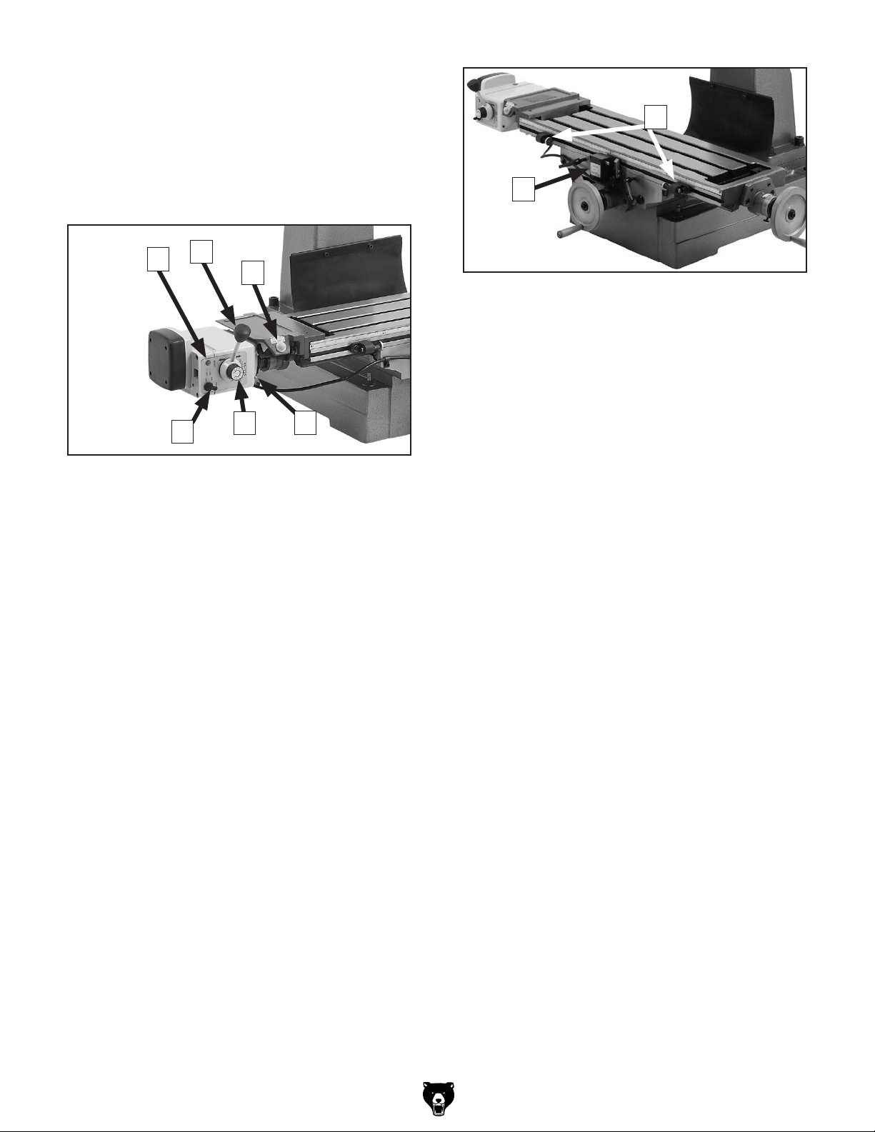
Power Feed Assembly
248-1
248
248-2
248-4
248-3
248-6
409
401
REF PART # DESCRIPTION
248 P0760248 POWER FEED ASSY ALIGN AS-235
248-1 P0760248-1 MOUNTING BRACKET 2-PC
248-2 P0760248-2 CONTROL HANDLE
248-3 P0760248-3 SPEED CONTROL KNOB
248-4 P0760248-4 ON/OFF SWITCH
248-5 P0760248-5 ZYTEL GEAR ASSEMBLY
248-6 P0760248-6 CAP SCREW M8-1.25 X 20
248-7 P0760248-7 DOWEL PIN 6 X 30
401 P0760401 MACHINE ID LABEL
409 P0760409 MODEL NUMBER LABEL
248-7
248-5
Attaching Power Feed
For shipping purposes, the power feed assembly
comes unattached from the table.
To attach power feed assembly:
1. DISCONNECT MACHINE FROM POWER!
2. Insert pins shown in Figure 1 into holes on
top of left side of table.
Pins
Cap Screws
Figure 1. Power feed assembly attached to
table.
3. Using a 6mm hex wrench, secure assembly with two M8-1.25 x 20 cap screws (see
Figure 1).
COPYRIGHT © JANUARY, 2014 BY GRIZZLY INDUSTRIAL, INC.
WARNING: NO PORTION OF THIS MANUAL MAY BE REPRODUCED IN ANY SHAPE
OR FORM WITHOUT THE WRITTEN APPROVAL OF GRIZZLY INDUSTRIAL, INC.
(FOR MODELS MANUFACTURED SINCE 12/13) #TS16257 PRINTED IN CHINA
Page 2
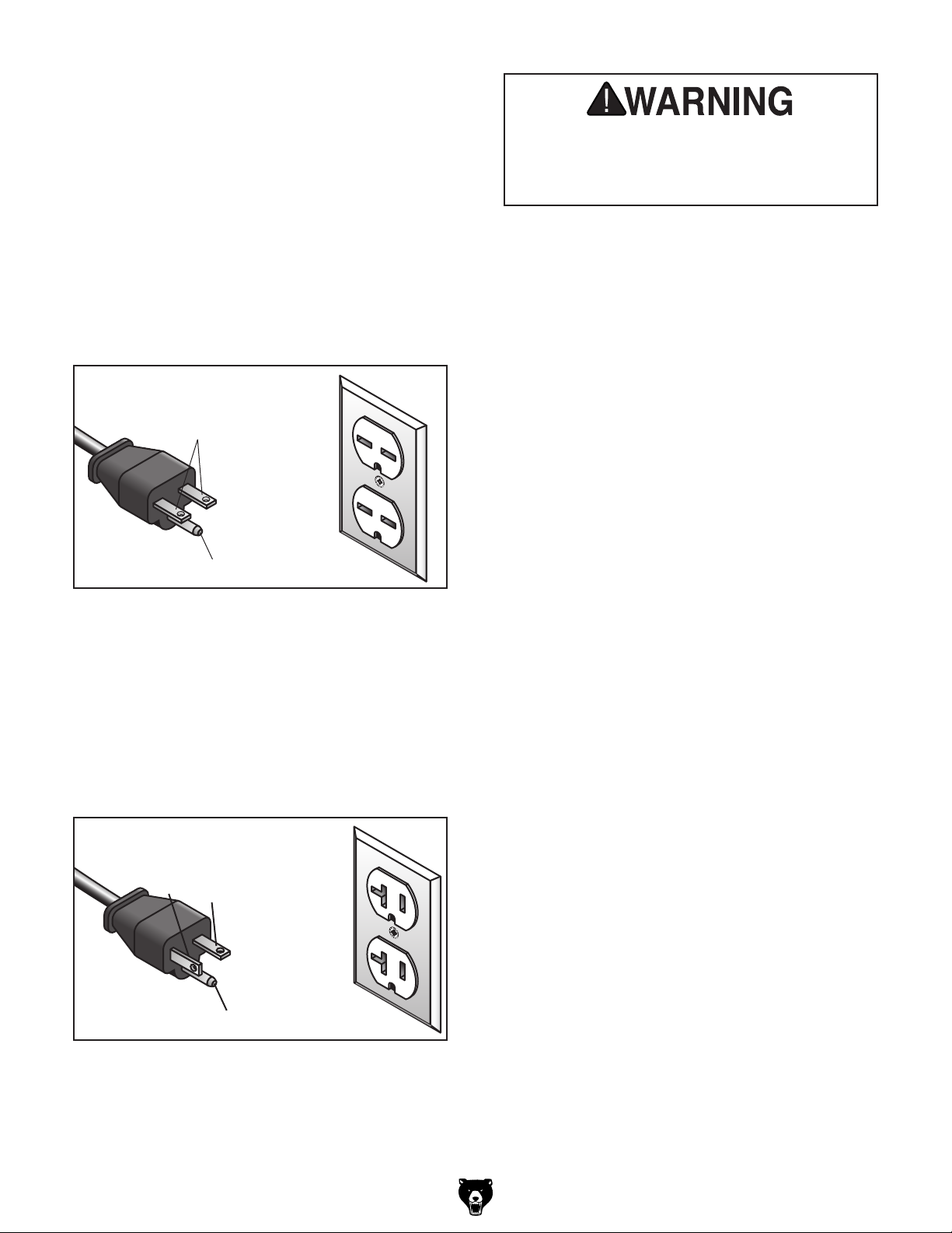
Power Feed Controls
Use Figures 18–19 and the following descriptions
to become familiar with the power feed controls.
Note: The power feed must be connected to an
independent, grounded 110V power supply to
operate.
G
H
A
Figure 18. X-axis power feed controls.
A. ON/OFF Light. Illuminates when unit is
turned ON.
B. Direction Lever. Controls direction of pow-
ered table travel.
C. Rapid Switch. When held down, moves
table rapidly in the direction chosen.
B
C
F
E
D
Figure 19. Limit switch and limit stops.
G. Limit Stops. Restrict table movement in their
locked position along front of table.
H. Limit Switch. Stops table movement when
either side plunger contacts a limit stop.
D. Power Light. Illuminates when unit is con-
nected to power.
E. Speed Dial. Controls rate of power feed.
F. ON/OFF Switch. Turns power feed ON and
OFF.
-2-
Model G0760 (Mfd. Since 12/13)
Page 3

MODEL G0705
MILL/DRILL w/STAND
OWNER'S MANUAL
COPYRIGHT © MARCH, 2010 BY GRIZZLY INDUSTRIAL, INC. REVISED APRIL, 2013 (TR)
WARNING: NO PORTION OF THIS MANUAL MAY BE REPRODUCED IN ANY SHAPE
OR FORM WITHOUT THE WRITTEN APPROVAL OF GRIZZLY INDUSTRIAL, INC.
(FOR MODELS MANUFACTURED SINCE 09/09) #JB12469 PRINTED IN CHINA
Page 4

This manual provides critical safety instructions on the proper setup,
operation, maintenance, and service of this machine/tool. Save this
document, refer to it often, and use it to instruct other operators.
Failure to read, understand and follow the instructions in this manual
may result in fire or serious personal injury—including amputation,
electrocution, or death.
The owner of this machine/tool is solely responsible for its safe use.
This responsibility includes but is not limited to proper installation in
a safe environment, personnel training and usage authorization,
proper inspection and maintenance, manual availability and comprehension, application of safety devices, cutting/sanding/grinding tool
integrity, and the usage of personal protective equipment.
The manufacturer will not be held liable for injury or property damage
from negligence, improper training, machine modifications or misuse.
Some dust created by power sanding, sawing, grinding, drilling, and
other construction activities contains chemicals known to the State
of California to cause cancer, birth defects or other reproductive
harm. Some examples of these chemicals are:
• Lead from lead-based paints.
• Crystalline silica from bricks, cement and other masonry products.
• Arsenic and chromium from chemically-treated lumber.
Your risk from these exposures varies, depending on how often you
do this type of work. To reduce your exposure to these chemicals:
Work in a well ventilated area, and work with approved safety equipment, such as those dust masks that are specially designed to filter
out microscopic particles.
Page 5

Table of Contents
INTRODUCTION ............................................... 2
Manual Accuracy ........................................... 2
Contact Info.................................................... 2
Machine Description ...................................... 2
Identification ................................................... 3
SECTION 1: SAFETY ....................................... 7
Safety Instructions for Machinery .................. 7
Additional Safety for Mill/Drills ....................... 9
SECTION 2: POWER SUPPLY ...................... 10
Availability ......................................................... 10
Full-Load Current Rating .................................. 10
Circuit Information ............................................. 10
Circuit Requirements for 220V .......................... 10
Circuit Requirements for 110V .......................... 10
Grounding Requirements .................................. 11
Extension Cords ................................................ 11
Voltage Conversion ........................................... 11
110V Conversion ......................................... 12
SECTION 3: SETUP ....................................... 15
Needed for Setup ......................................... 15
Unpacking .................................................... 15
Inventory ...................................................... 16
Cleanup ........................................................ 17
Site Considerations ...................................... 18
Mounting Options ......................................... 19
Using the Included Leveling Bolt ......................19
Using Machine Mounts .....................................20
Anchoring to Concrete Floors ........................... 20
Mounting to a Workbench ................................. 21
Assembly ..................................................... 21
Moving & Placing Machine .......................... 22
Leveling ............................................................. 22
Test Run ...................................................... 23
Break-In ....................................................... 24
SECTION 5: ACCESSORIES ......................... 36
SECTION 6: MAINTENANCE ......................... 38
Schedule ...................................................... 38
Cleaning and Protecting .............................. 38
Lubrication ................................................... 39
Table Leadscrews ............................................. 39
SECTION 7: SERVICE ................................... 41
Troubleshooting ........................................... 41
Gibs .............................................................. 43
Leadscrew Backlash .................................... 44
SECTION 8: WIRING ...................................... 45
Wiring Safety Instructions ............................ 45
G0705 Wiring Diagram ................................ 46
SECTION 9: PARTS ....................................... 48
Headstock Parts Breakdown ....................... 48
Headstock Parts List .................................... 49
Base Parts Breakdown ................................ 51
Base Parts List ............................................. 52
Electrical Components Breakdown & List .... 53
Labels Breakdown and List.......................... 54
WARRANTY AND RETURNS ........................ 57
SECTION 4: OPERATIONS ........................... 25
Operation Overview ..................................... 25
Basic Controls .............................................. 26
Calculating Spindle Speed for Milling .......... 28
Speed Changes ........................................... 29
Calculating Spindle Speed for Drilling ......... 30
Using the Drill Bit Speed Chart ......................... 30
Lubrication Suggestions .................................... 30
Spindle Height.............................................. 31
Loading Tooling ........................................... 32
Drill Chuck Arbor .......................................... 33
Collet Adapters ............................................ 33
Headstock Position ...................................... 34
Depth Stop ................................................... 34
Table Travel ................................................. 35
Graduated Dials ........................................... 35
Page 6

INTRODUCTION
We stand behind our machines. If you have
any questions or need help, use the information
below to contact us. Before contacting, please get
the serial number and manufacture date of your
machine. This will help us help you faster.
We want your feedback on this manual. What did
you like about it? Where could it be improved?
Please take a few minutes to give us feedback.
Email: manuals@grizzly.com
We are proud to offer this manual with your new
machine! We've made every effort to be exact
with the instructions, specifications, drawings,
and photographs of the machine we used when
writing this manual. However, sometimes we still
make
Also, owing to our policy of continuous improvement, your machine may not exactly match the
manual. If you find this to be the case, and the dif-
ference between the manual and machine leaves
you in doubt,
manual update or call technical support for help.
Before calling, find the manufacture date of your
machine by looking at the date stamped into the
machine ID label (see below). This will help us
determine if the manual version you received
matches the manufacture date of your machine.
For your convenience, we
-
uals and
on our website
at
model
of
as soon as they are complete.
Manual Accuracy
an occasional mistake.
www.grizzly.com. Any updates to your
machine will be reflected in these documents
check our website for the latest
Manufacture Date
of Your Machine
post all available man
manual updates for free
Contact Info
Grizzly Technical Support
1203 Lycoming Mall Circle
Muncy, PA 17756
Phone: (570) 546-9663
Email: techsupport@grizzly.com
Grizzly Documentation Manager
P.O. Box 2069
Bellingham, WA 98227-2069
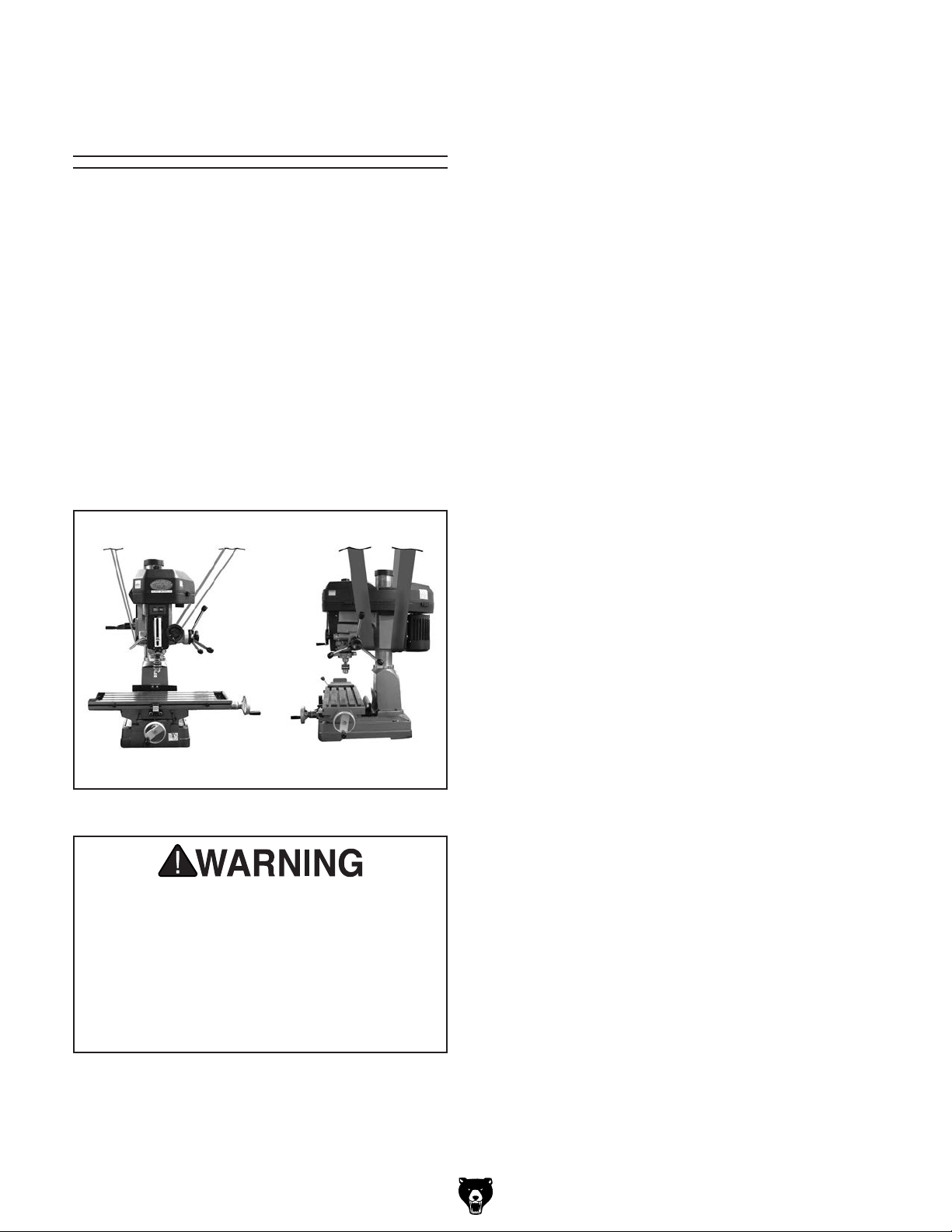
Machine Description
The mill/drill is used to shape metal workpieces
by removing material with the use of a rotating
cutting tool.
In milling operations, the location of the cutting
tool is stationary while the workpiece is fed into
the cutter by moving the table.
In drilling operations, the workpiece is held stationary on the table while the cutting tool is fed
vertically into the workpiece with the movement of
the spindle and head.
-2-
Model G0705 (Mfg. since 09/09)
Page 7

Identification
B
A
V
U
T
S
R
J
K
M
C
D
E
F
G
H
I
L
W
Detail of left side of
machine
J
K
Q
P
Figure 1. Model G0705 identification.
A. Control Panel
B. Drawbar & Cap
C. Belt Cover
D. Motor
E. Coarse Downfeed Lever
F. Fine Downfeed Lock Knob
G. Fine Downfeed Handwheel
H. Column
I. Table
J. Longitudinal Handwheel
K. Table Stop
L. Cross Travel Lock
M
N
O
M. Longitudinal Travel Lock
N. Cabinet Stand
O. Mounting Bolt Hole
P. Cabinet Door
Q. Cross Travel Handwheel
R. Chuck
S. Spindle
T. Depth Stop
U. Quill Lock Lever
V. Depth Scale
W. Headstock Elevation Crank
Model G0705 (Mfg. since 09/09)
-3-
Page 8

MACHINE DATA
SHEET
Customer Service #: (570) 546-9663 · To Order Call: (800) 523-4777 · Fax #: (800) 438-5901
MODEL G0705 DRILL/MILL WITH STAND 29 INCH X 8 INCH
TABLE
Product Dimensions:
Weight.............................................................................................................................................................. 617 lbs.
Width (side-to-side) x Depth (front-to-back) x Height........................................................ 41-5/8 x 40-1/2 x 43-1/4 in.
Footprint (Length x Width)............................................................................................................... 28-3/8 x 17-3/4 in.
Space Required for Full Range of Movement (Width x Depth).............................................................. 61-1/2 x 44 in.
Shipping Dimensions:
Carton #1
Type................................................................................................................................................ Wood Crate
Content................................................................................................................................................. Machine
Weight.................................................................................................................................................... 750 lbs.
Length x Width x Height............................................................................................................. 38 x 30 x 46 in.
Must Ship Upright......................................................................................................................................... Yes
Carton #2
Type........................................................................................................................................... Cardboard Box
Content...................................................................................................................................................... Stand
Weight...................................................................................................................................................... 84 lbs.
Length x Width x Height............................................................................................................. 29 x 19 x 23 in.
Must Ship Upright.......................................................................................................................................... No
Electrical:
Power Requirement............................................................................................. 110V or 220V, Single-Phase, 60 Hz
Prewired Voltage.................................................................................................................................................. 220V
Full-Load Current Rating................................................................................................. 17.8A at 110V, 8.6A at 220V
Minimum Circuit Size.......................................................................................................... 20A at 110V, 15A at 220V
Connection Type....................................................................................................................................... Cord & Plug
Power Cord Included.............................................................................................................................................. Yes
Power Cord Length.......................................................................................................................................... 6-1/2 ft.
Power Cord Gauge......................................................................................................................................... 14 AWG
Plug Included........................................................................................................................................................... No
Recommended Plug Type............................................................................................... 6-15 for 220V, 5-20 for 110V
Switch Type............................................................................................ Control Panel w/Magnetic Switch Protection
Voltage Conversion Kit.................................................................................................................. P0705311 for 110V
-4-
Motors:
Main
Type................................................................................................................. TEFC Capacitor-Start Induction
Horsepower................................................................................................................................................ 2 HP
Phase............................................................................................................................................ Single-Phase
Amps................................................................................................................................................. 17.8A/8.6A
Speed................................................................................................................................................ 1725 RPM
Power Transfer .................................................................................................................................. Belt Drive
Bearings..................................................................................................... Shielded & Permanently Lubricated
The information contained herein is deemed accurate as of 8/15/2013 and represents our most recent product specifications.
Due to our ongoing improvement efforts, this information may not accurately describe items previously purchased.
Model G0705 (Mfg. since 09/09)
PAGE 1 OF 3Model G0705
Page 9

Main Specifications:
Operation Info
Spindle Travel.................................................................................................................................... 4-11/16 in.
Max Distance Spindle to Column.......................................................................................................... 7-3/4 in.
Max Distance Spindle to Table.......................................................................................................... 17-5/16 in.
Longitudinal Table Travel (X-Axis).................................................................................................. 19-11/16 in.
Cross Table Travel (Y-Axis).................................................................................................................. 7-1/2 in.
Drilling Capacity for Cast Iron.............................................................................................................. 1-3/16 in.
Drilling Capacity for Steel............................................................................................................................ 1 in.
End Milling Capacity................................................................................................................................. 3/4 in.
Face Milling Capacity................................................................................................................................... 3 in.
Table Info
Table Length........................................................................................................................................ 28-3/4 in.
Table Width........................................................................................................................................... 8-1/4 in.
Table Thickness.................................................................................................................................... 2-1/2 in.
Number of T-Slots............................................................................................................................................ 3
T-Slot Size................................................................................................................................................ 5/8 in.
T-Slots Centers...................................................................................................................................... 2-1/2 in.
Spindle Info
Spindle Taper............................................................................................................................................... R-8
Number of Vertical Spindle Speeds................................................................................................................ 12
Range of Vertical Spindle Speeds........................................................................................... 140 – 2436 RPM
Quill Diameter......................................................................................................................................... 2.95 in.
Drawbar Thread Size............................................................................................................................. 7/16-20
Drawbar Length............................................................................................................................... 17-11/16 in.
Spindle Bearings......................................................................................................... Tapered Roller Bearings
Construction
Spindle Housing/Quill........................................................................................................................... Cast Iron
Table....................................................................................................................... Precision-Ground Cast Iron
Head.................................................................................................................................................... Cast Iron
Column/Base....................................................................................................................................... Cast Iron
Base..................................................................................................................................................... Cast Iron
Stand.......................................................................................................................................................... Steel
Paint....................................................................................................................................................... Enamel
Other Specifications:
Country Of Origin ............................................................................................................................................... China
Warranty ........................................................................................................................................................... 1 Year
Approximate Assembly & Setup Time .............................................................................................................. 1 Hour
Serial Number Location ...................................................................................................... ID Label on Head Casting
Sound Rating .................................................................................................................................................. < 80 dB
ISO 9001 Factory .................................................................................................................................................. Yes
CSA Certified .......................................................................................................................................................... No
Features:
Calibrated depth stop
Fine feed downfeed control, graduated in 0.001 in.
Coolant trough
Replaceable brushes on universal motor
Quill moves 0.108 in. per revolution of fine feed handwheel
Table moves 0.100 in. per revolution of handwheel
Model G0705 (Mfg. since 09/09)
-5-
Page 10

Accessories Included:
Drill chuck 1/16-1/2 in. with MT#3 spindle taper
Tool box
Chuck key
Drift
Oil bottle
Hex wrenches
Locking nuts for leveling feet
R8 to MT#3 adapter
MT#3 to MT#2 adapter
Two T-bolts
-6-
The information contained herein is deemed accurate as of 8/15/2013 and represents our most recent product specifications.
Due to our ongoing improvement efforts, this information may not accurately describe items previously purchased.
Model G0705 (Mfg. since 09/09)
PAGE 3 OF 3Model G0705
Page 11

SECTION 1: SAFETY
For Your Own Safety, Read Instruction
Manual Before Operating This Machine
The purpose of safety symbols is to attract your attention to possible hazardous conditions.
This manual uses a series of symbols and signal words intended to convey the level of importance of the safety messages. The progression of symbols is described below. Remember that
safety messages by themselves do not eliminate danger and are not a substitute for proper
accident prevention measures. Always use common sense and good judgment.
Indicates an imminently hazardous situation which, if not avoided,
WILL result in death or serious injury.
Indicates a potentially hazardous situation which, if not avoided,
COULD result in death or serious injury.
Indicates a potentially hazardous situation which, if not avoided,
MAY result in minor or moderate injury. It may also be used to alert
against unsafe practices.
This symbol is used to alert the user to useful information about
NOTICE
proper operation of the machine.
Safety Instructions for Machinery
OWNER’S MANUAL. Read and understand this
owner’s manual BEFORE using machine.
TRAINED OPERATORS ONLY. Untrained operators have a higher risk of being hurt or killed.
Only allow trained/supervised people to use this
machine. When machine is not being used, disconnect power, remove switch keys, or lock-out
machine to prevent unauthorized use—especially
around children. Make workshop kid proof!
DANGEROUS ENVIRONMENTS. Do not use
machinery in areas that are wet, cluttered, or have
poor lighting. Operating machinery in these areas
greatly increases the risk of accidents and injury.
MENTAL ALERTNESS REQUIRED. Full mental
alertness is required for safe operation of machinery. Never operate under the influence of drugs or
alcohol, when tired, or when distracted.
ELECTRICAL EQUIPMENT INJURY RISKS. You
can be shocked, burned, or killed by touching live
electrical components or improperly grounded
machinery. To reduce this risk, only allow qualified
service personnel to do electrical installation or
repair work, and always disconnect power before
accessing or exposing electrical equipment.
DISCONNECT POWER FIRST.
nect machine from power supply BEFORE making
adjustments, changing tooling, or servicing machine.
This prevents an injury risk from unintended startup
or contact with live electrical components.
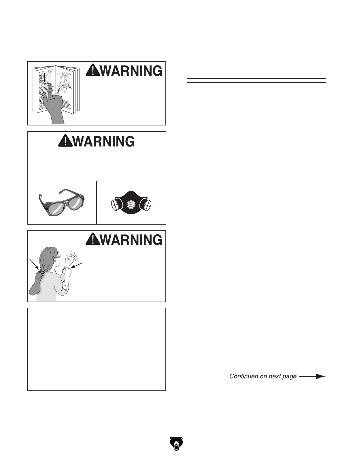
EYE PROTECTION. Always wear ANSI-approved
safety glasses or a face shield when operating or
observing machinery to reduce the risk of eye
injury or blindness from flying particles. Everyday
eyeglasses are NOT approved safety glasses.
Always discon-
Model G0705 (Mfg. since 09/09)
-7-
Page 12

WEARING PROPER APPAREL. Do not wear
clothing, apparel or jewelry that can become
entangled in moving parts. Always tie back or
cover long hair. Wear non-slip footwear to avoid
accidental slips, which could cause loss of workpiece control.
HAZARDOUS DUST. Dust created while using
machinery may cause cancer, birth defects, or
long-term respiratory damage. Be aware of dust
hazards associated with each workpiece material,
and always wear a NIOSH-approved respirator to
reduce your risk.
HEARING PROTECTION. Always wear hearing protection when operating or observing loud
machinery. Extended exposure to this noise
without hearing protection can cause permanent
hearing loss.
REMOVE ADJUSTING TOOLS. Tools left on
machinery can become dangerous projectiles
upon startup. Never leave chuck keys, wrenches,
or any other tools on machine. Always verify
removal before starting!
USE CORRECT TOOL FOR THE JOB. Only use
this tool for its intended purpose—do not force
it or an attachment to do a job for which it was
not designed. Never make unapproved modifications—modifying tool or using it differently than
intended may result in malfunction or mechanical
failure that can lead to personal injury or death!
AWKWARD POSITIONS. Keep proper footing
and balance at all times when operating machine.
Do not overreach! Avoid awkward hand positions
that make workpiece control difficult or increase
the risk of accidental injury.
CHILDREN & BYSTANDERS. Keep children and
bystanders at a safe distance from the work area.
Stop using machine if they become a distraction.
FORCING MACHINERY. Do not force machine.
It will do the job safer and better at the rate for
which it was designed.
NEVER STAND ON MACHINE. Serious injury
may occur if machine is tipped or if the cutting
tool is unintentionally contacted.
STABLE MACHINE. Unexpected movement during operation greatly increases risk of injury or
loss of control. Before starting, verify machine is
stable and mobile base (if used) is locked.
USE RECOMMENDED ACCESSORIES. Consult
this owner’s manual or the manufacturer for recommended accessories. Using improper accessories will increase the risk of serious injury.
UNATTENDED OPERATION. To reduce the
risk of accidental injury, turn machine OFF and
ensure all moving parts completely stop before
walking away. Never leave machine running
while unattended.
MAINTAIN WITH CARE. Follow all maintenance
instructions and lubrication schedules to keep
machine in good working condition. A machine
that is improperly maintained could malfunction,
leading to serious personal injury or death.
CHECK DAMAGED PARTS. Regularly inspect
machine for any condition that may affect safe
operation. Immediately repair or replace damaged
or mis-adjusted parts before operating machine.
MAINTAIN POWER CORDS. When disconnecting cord-connected machines from power, grab
and pull the plug—NOT the cord. Pulling the cord
may damage the wires inside. Do not handle
cord/plug with wet hands. Avoid cord damage by
keeping it away from heated surfaces, high traffic
areas, harsh chemicals, and wet/damp locations.
GUARDS & COVERS. Guards and covers reduce
accidental contact with moving parts or flying
debris. Make sure they are properly installed,
undamaged, and working correctly.
-8-
EXPERIENCING DIFFICULTIES. If at any time
you experience difficulties performing the intended operation, stop using the machine! Contact our
Technical Support at (570) 546-9663.
Model G0705 (Mfg. since 09/09)
Page 13

Additional Safety for Mill/Drills
UNDERSTANDING CONTROLS. Make sure you
understand the use and operation of all controls.
SAFETY ACCESSORIES. Always use a chip
guard in addition to your safety glasses when milling to prevent bodily injury.
WORK HOLDING. Before starting the machine,
be certain the workpiece has been properly
clamped to the table. NEVER hold the workpiece
by hand when using the mill.
CHUCK KEY SAFETY. Always remove your
chuck key, drawbar wrench, and any service tools
immediately after use.
SPINDLE SPEEDS. Select the spindle speed
that is appropriate for the type of work and material. Allow the mill/drill to gain full speed before
beginning a cut.
POWER DISRUPTION. In the event of a local
power outage during use of the mill, turn OFF all
switches to avoid possible sudden start up once
power is restored.
SPINDLE DIRECTION CHANGES. Never
reverse spindle direction when milling, boring, or
facing a workpiece.
STOPPING SPINDLE. DO NOT stop the mill/drill
using your hand against the chuck.
BE ATTENTIVE. DO NOT leave mill/drill running
unattended for any reason.
MACHINE CARE AND MAINTENANCE. Never
operate the mill/drill with damaged or worn parts.
Maintain your mill/drill in proper working condition.
Perform routine inspections and maintenance
promptly. Put away adjustment tools after use.
DISCONNECT POWER. Make sure the mill is
turned OFF, disconnected from its power source,
and all moving parts have come to a complete
stop before starting any inspection, adjustment,
or maintenance procedure.
AVOIDING ENTANGLEMENT. Keep loose clothing articles such as sleeves, belts, or jewelry
items away from the mill spindle. Never wear
gloves when operating the mill.
TOOL HOLDING. Always use the proper tools for
the material you are milling. Make sure they are
held firmly in the proper tool holder for the job.
CLEAN-UP. DO NOT clear chips by hand. Use
a brush, and never clear chips while the mill is
turning.
CUTTING TOOL INSPECTION. Inspect drills and
end mills for sharpness, chips, or cracks before
each use. Replace dull, chipped, or cracked cutting tools immediately. Handle new cutting tools
with care. Leading edges are very sharp and can
cause lacerations.
EXPERIENCING DIFFICULTIES. If at any time
you are experiencing difficulties performing the
intended operation, stop using the machine!
Contact our Technical Support at (570) 546-9663.
No list of safety guidelines can be complete. Every shop environment is different. Like all
machines there is danger associated with the Model G0705. Accidents are frequently caused by
lack of familiarity or failure to pay attention. Use this machine with respect and caution to lessen
the possibility of operator injury. If normal safety precautions are overlooked or ignored, serious
personal injury may occur.
Model G0705 (Mfg. since 09/09)
-9-
Page 14

SECTION 2: POWER SUPPLY
Before installing the machine, consider the availability and proximity of the required power supply
circuit. If an existing circuit does not meet the
requirements for this machine, a new circuit must
be installed. To minimize the risk of electrocution,
fire, or equipment damage, installation work and
electrical wiring must be done by an electrican or
qualified service personnel in accordance with all
applicable codes and standards.
Electrocution, fire, or
equipment damage may
occur if machine is not
correctly grounded and
connected to the power
The full-load current rating is the amperage a
machine draws at 100% of the rated output power.
On machines with multiple motors, this is the
amperage drawn by the largest motor or sum of all
motors and electrical devices that might operate
at one time during normal operations.
The full-load current is not the maximum amount
of amps that the machine will draw. If the machine
is overloaded, it will draw additional amps beyond
the full-load rating.
If the machine is overloaded for a sufficient length
of time, damage, overheating, or fire may result—
especially if connected to an undersized circuit.
To reduce the risk of these hazards, avoid overloading the machine during operation and make
sure it is connected to a power supply circuit that
meets the requirements in the following section.
For your own safety and protection of
Note: The circuit requirements listed in this manual apply to a dedicated circuit—where only one
machine will be running at a time. If this machine
will be connected to a shared circuit where multiple machines will be running at the same time,
consult a qualified electrician to ensure that the
circuit is properly sized for safe operation.
A power supply circuit includes all electrical
equipment between the breaker box or fuse panel
in the building and the machine. The power supply circuit used for this machine must be sized to
safely handle the full-load current drawn from the
machine for an extended period of time. (If this
machine is connected to a circuit protected by
fuses, use a time delay fuse marked D.)
This machine is prewired to operate on a 220V
power supply circuit that has a verified ground and
meets the following requirements:
This machine can be converted to operate on a
110V power supply (refer to Voltage Conversion
instructions) that has a verified ground and meets
the following requirements:
Availability
supply.
Full-Load Current Rating
Circuit Information
property, consult an electrician if you are
unsure about wiring practices or electrical
codes in your area.
Full-Load Current Rating at 220V .... 8.6 Amps
Full-Load Current Rating at 110V ....17. 8 Amps
-10 -
Circuit Requirements for 220V
Nominal Voltage .............................. 220V/240V
Cycle .......................................................... 60 Hz
Phase ........................................... Single-Phase
Circuit Rating ...................................... 15 Amps
Plug/Receptacle ............................. NEMA 6 -15
Circuit Requirements for 110V
Nominal Voltage ...............................110V/120V
Cycle .......................................................... 60 Hz
Phase ........................................... Single-Phase
Circuit Rating ...................................... 20 Amps
Plug/Receptacle ............................. NEMA 5-20
Model G0705 (Mfg. since 09/09)
Page 15
Improper connection of the equipment-grounding
wire can result in a risk of electric shock. The
wire with green insulation (with or without yellow
stripes) is the equipment-grounding wire. If repair
or replacement of the power cord or plug is necessary, do not connect the equipment-grounding
wire to a live (current carrying) terminal.
Check with a qualified electrician or service personnel if you do not understand these grounding
requirements, or if you are in doubt about whether
the tool is properly grounded. If you ever notice
that a cord or plug is damaged or worn, disconnect it from power, and immediately replace it with
a new one.
We do not recommend using an extension cord
with this machine.
cord, only use it if absolutely necessary and only
on a temporary basis.
Extension cords cause voltage drop, which may
damage electrical components and shorten motor
life. Voltage drop increases as the extension cord
size gets longer and the gauge size gets smaller
(higher gauge numbers indicate smaller sizes).
Any extension cord used with this machine must
contain a ground wire, match the required plug
and receptacle, and meet the following requirements:
Grounding Requirements
This machine MUST be grounded. In the event
of certain malfunctions or breakdowns, grounding
reduces the risk of electric shock by providing a
path of least resistance for electric current.
For 220V operation: This machine is equipped
with a power cord that has an equipment-grounding wire and a grounding plug (see following figure). The plug must only be inserted into a matching receptacle (outlet) that is properly installed
and grounded in accordance with all local codes
and ordinances.
For 110V operation: The plug specified under
“
ous page has a grounding prong that must be
attached to the equipment-grounding wire inside
the included power cord. The plug must only be
inserted into a matching receptacle (see below)
that is properly installed and grounded in accordance with all local codes and ordinances.
GROUNDED
6-15 RECEPTACLE
Current Carrying Prongs
6-15 PLUG
Serious injury could occur if you connect
the machine to power before completing the
setup process. DO NOT connect to power
until instructed later in this manual.
Grounding Prong
Figure 2. Typical 6-15 plug and receptacle.
Circuit Requirements for 110V” on the previ
GROUNDED
5-20 RECEPTACLE
Hot
Neutral
Figure 3. Typical 5-20 plug and receptacle.
Model G0705 (Mfg. since 09/09)
Grounding Prong
5-20 PLUG
Extension Cords
If you must use an extension
Minimum Gauge Size ...........................12 AWG
Maximum Length (Shorter is Better).......50 ft.
Voltage Conversion
The voltage conversion MUST be performed by
a qualified electrician. To perform the voltage
conversion, follow 110V Conversion on the next
page. If the diagram included on the motor con-
flicts with the one in this manual, the motor may
have changed since the manual was printed. Use
the diagram provided on the motor.
-11-
Page 16

110V Conversion
GND
Contactor Information
(Contactor is wired the same for 110V/220V)
The Model G0705 can be converted for 110V
operation. This conversion job consists of disconnecting the machine from the power source,
replacing the contactors and power indicator
lamp, and rewiring the motor.
The necessary components for this procedure
can be purchased in the Model G0705 110 V
Conversion Kit (Part No. P0705311) by calling
Grizzly Customer Service at (800) 523-4777.
All wiring changes must be inspected by a qualified electrician before the machine is connected
to the power source. If, at any time during this procedure you need help, call Grizzly Tech Support
at (570) 546-9663.
To rewire the Model G0705 for 110V operation:
1. DISCONNECT MACHINE FROM POWER!
2. Remove the electrical box and motor junction
box covers shown in Figure 4.
Contactors
Control Panel (Viewed From Behind)
Indicator
Lamp
V1
V1
2T1
U2
U2
4T2
V2
7
6T3
N
A2
5
2T1
7
5
4T2
5
6T3
N
N
A2
Indicator Light Type XDJ2(J) 220V AC
Indicator Light Type XDJ2(J) 110V AC
(Indicator is wired the same for 110V/220V)
7
4
3
REV
4
EMERGENCY
STOP
BUTTON
2
2
1
14NO
22NC
32NC
44NO
14NO
22NC
32NC
44NO
1
1
13NO
21NC
31NC
CONTACTOR
SIEMENS KM1
43NO
13NO
21NC
31NC
CONTACTOR
SIEMENS KM2
43NO
X1
1
8
X2
N
N
1L1
L
3L2
L
5L3
4
4
4
L
1L1
4
6
3L2
L
L
5L3
5
3
4
4
POWER
INDICATOR
LAMP
N
STOP
BUTTON
3
2
A1
A1
FWD
1
6
8
2
Motor Junction
Indicator Lamp
Box Cover
Electrical Box
Cover
Figure 4. Cover locations.
3. Use a Phillips screwdriver to remove all of
the wires that connect to the two contactors
shown in Figures 5 & 6. If any of the wires
are not clearly labeled, label them before
removing to ensure that they will be replaced
in the proper locations. Refer to SECTION 8:
WIRING starting on Page 45 for detailed wiring diagrams.
Figure 5. Partial wiring diagram.
Figure 6. Removing contactors.
-12-
Model G0705 (Mfg. since 09/09)
Page 17

4. Remove the screws that secure the brass
Ground
To Electrical Box
To Electrical Box
contactor mounting plate to the back of the
electrical box, then pull the contactors out
to access the gray tab shown in Figure 7.
Pull outward on the gray tab to release each
contactor from the mounting plate.
Mounting Plate
10. Locate the terminal block located in the motor
junction box, shown in Figure 8.
Motor 220V
Terminal Block
110V Terminal
Block Jumper
Position.
(Wire positions
are the same for
110V/220V)
U1
Z2
W2
V1
U2
Z1
V2
W1
Run
Capacitor
20 MFD
450 VAC
U1
Z2
U2
W2
V1
U2
Z1
V1
U1
V2
W1
PE
V2
Start
Capacitor
150 MFD
250 VAC
Gray Tab
Figure 7. Contactor release tab location.
5. Install the two 110V contactors from the
Model G0705 110V Conversion Kit in place
of the contactors you removed in Step 4.
6. Replace the wires you removed in Step 3
to the corresponding terminals on the 110V
contactors. The wiring is the same for 110V
and 220V. Refer to SECTION 8: WIRING
starting on Page 45 for detailed wiring diagrams.
7. Locate the indicator lamp shown in Figures 4
& 5. Disconnect the two wires from its terminals, then remove the lamp.
8. Install the 110V indicator lamp from the
Model G0705 110V Conversion Kit in place
of the lamp you removed in Step 7.
Jumpers Moved
for 110V
220V Jumper
Location
Figure 8. Jumper positions on terminal block.
9. Connect the wires you removed in Step 7 to
the corresponding terminals on the 110V indicator lamp. The wiring is the same for 110V
and 220V.
Model G0705 (Mfg. since 09/09)
-13-
Page 18

Hot
Hot
Ground
6-15 Plug
(As Recommended)
G
Ground
PE
V2
V1
U2
U1
U2
V1
V2
Z1
W1
Z2
W2
U1
U2
V1
V2
Z1
W1
Z2
W2
U1
To Electrical Box
Start
Capacitor
150 MFD
250 VAC
Run
Capacitor
20 MFD
450 VAC
110V Terminal
Block Jumper
Position.
(Wire positions
are the same for
110V/220V)
To Electrical Box
Motor 220V
11. Use a Phillips screwdriver to remove the
screws that secure the two metal jumpers
to the terminal block, as shown in Figure 9,
then remove both jumpers. Be careful not to
mix up the locations of any of the wires while
you do so.
14. Install a NEMA 5-20 plug such as the one
shown in Figure 3 onto the power cord, as
illustrated in Figure 10. Refer to SECTION
8: WIRING starting on Page 45 for detailed
wiring diagrams.
Cord Rewired for 110V
Neutral
Hot
110 VAC
Ground
Figure 10. Cord rewired for 110V.
5-20 Plug
(As Recommended)
Figure 9. Changing motor jumper positions.
12. Place both of the jumpers into the 110V location shown in Figure 8.
13. Replace the screws you removed in Step
11, making sure all wires are secured in the
same positions they were originally in, as
shown in Figure 8. Refer to SECTION 8:
WIRING starting on Page 45 for detailed wiring diagrams.
-14-
Model G0705 (Mfg. since 09/09)
Page 19

SECTION 3: SETUP
Your machine was carefully packaged for safe
transportation. Remove the packaging materials
from around your machine and inspect it. If you
discover any damage, please call us immediately
at (570) 546-9663
Save the containers and all packing materials for
possible inspection by the carrier or its agent.
Otherwise, filing a freight claim can be difficult.
When you are completely satisfied with the condition of your shipment, inventory the contents.
Keep children and pets away
from plastic bags or packing
materials shipped with this
Needed for Setup
This machine presents
serious injury hazards
to untrained users. Read
through this entire manual to become familiar with
the controls and operations before starting the
machine!
Wear safety glasses during the entire setup process!
The following are needed to complete the setup
process:
Description Qty
• Precision Level ........................................... 1
• Safety Glasses (for each person) ............... 1
• Solvent/Cleaner .......................................... 1
• Shop Rags .................................................. 1
• Brass Hammer ........................................... 1
• Lifting Straps (Rated for at least 750 lbs.) . . 2
• Lifting Equipment
(Rated for at least 750 lbs.) ........................ 1
• Another Person .......................................... 1
The Model G0705 is a
heavy machine. Serious
personal injury may occur
if safe moving methods are not used. To be
safe, get assistance and
use power equipment to
move the shipping crate
and remove the machine
from the crate.
Unpacking
for advice.
SUFFOCATION HAZARD!
machine. Discard immediately.
Model G0705 (Mfg. since 09/09)
-15-
Page 20

Inventory
The following is a list of items shipped with your
machine. Before beginning setup, lay these items
out and inventory them.
If any non-proprietary parts are missing (e.g. a
nut or a washer), we will gladly replace them; or
for the sake of expediency, replacements can be
obtained at your local hardware store.
Crate Contents (Figures 11 & 12) Qty
A. Cabinet Base .............................................. 1
B. Machine ...................................................... 1
C. Toolbox ....................................................... 1
D. Drill Chuck B16 1–13mm ............................ 1
E. Drill Chuck Arbor R8–B16 .......................... 1
F. Lug Wrench ................................................ 1
G. T-Bolt Assemblies ....................................... 2
—T-Bolt M14-2 x 55 .................................... 2
—Flat Washer 14mm .................................. 2
—Hex Bolt M14-2 ....................................... 2
H. Drill Chuck Key ........................................... 1
I. Drift Key ...................................................... 1
J. Collet Adapter R8 to MT#3 ......................... 1
K. Collet Adapter MT#3 to MT#2 .................... 1
L. Bottle For Oil .............................................. 1
Not Shown
• Hex Wrenches 3, 4, 5mm ..................1 Each
• Hex Bolts M10-1.25 x 140 ........................... 4
• Flat Washers 10mm ................................... 4
• Lock Washers 10mm .................................. 4
• Open-End Combo Wrench 17/19mm ......... 1
• Hex Bolts M12-1.75 x 40 ............................. 4
• Hex Nuts M12-1.75 ..................................... 4
• Cap Screws M6-1 x 16 ............................... 3
• Flat Washers 6mm ..................................... 3
• Drawbar ...................................................... 1
A
B
Figure 11. Main inventory.
C
H
G
E
L
K
J
I
Figure 12. Inventory.
F
D
NOTICE
If you cannot find an item on this list, carefully check around/inside the machine and
packaging materials. Often, these items get
lost in packaging materials while unpacking or they are pre-installed at the factory.
-16 -
Model G0705 (Mfg. since 09/09)
Page 21

The unpainted surfaces of your machine are
coated with a heavy-duty rust preventative that
prevents corrosion during shipment and storage.
This rust preventative works extremely well, but it
will take a little time to clean.
Be patient and do a thorough job cleaning your
machine. The time you spend doing this now will
give you a better appreciation for the proper care
of your machine's unpainted surfaces.
There are many ways to remove this rust preventative, but the following steps work well in a wide
variety of situations. Always follow the manufacturer’s instructions with any cleaning product you
use and make sure you work in a well-ventilated
area to minimize exposure to toxic fumes.
Before cleaning, gather the following:
• Disposable rags
• Cleaner/degreaser (WD•40 works well)
• Safety glasses & disposable gloves
• Plastic paint scraper (optional)
Basic steps for removing rust preventative:
1.
2.
3.
4.
Many cleaning solvents
work in a well-ventilated
Avoid chlorine-based solvents, such as
Cleanup
Gasoline and petroleum
products have low flash
points and can explode
or cause fire if used to
clean machinery. A v oi d
using these products
to clean machinery.
Put on safety glasses.
Coat the rust preventative with a liberal
amount of cleaner/degreaser, then let it soak
for 5–10 minutes.
Wipe off the surfaces. If your cleaner/degreas-
er is effective, the rust preventative will wipe
off easily. If you have a plastic paint scraper,
scrape off as much as you can first, then wipe
off the rest with the rag.
are toxic if inhaled. Only
area.
NOTICE
acetone or brake parts cleaner, that may
damage painted surfaces.
T23692—Orange Power Degreaser
A great product for removing the waxy shipping
grease from your machine during clean up.
Figure 13. T23692 Orange Power Degreaser.
Repeat Steps 2–3 as necessary until clean,
then coat all unpainted surfaces with a quality
metal protectant to prevent rust.
Model G0705 (Mfg. since 09/09)
-17-
Page 22

Site Considerations
Weight Load
Physical Environment
Place this machine near an existing power source.
Shadows, glare, or strobe effects that may distract
Refer to the Machine Data Sheet for the weight
of your machine. Make sure that the surface upon
which the machine is placed will bear the weight
of the machine, additional equipment that may be
installed on the machine, and the heaviest workpiece that will be used. Additionally, consider the
weight of the operator and any dynamic loading
that may occur when operating the machine.
Space Allocation
Consider the largest size of workpiece that will
be processed through this machine and provide
enough space around the machine for adequate
operator material handling or the installation of
auxiliary equipment. With permanent installations,
leave enough space around the machine to open
or remove doors/covers as required by the maintenance and service described in this manual.
See below for required space allocation.
Children or untrained people
may be seriously injured by
this machine. Only install in an
access restricted location.
The physical environment where the machine is
operated is important for safe operation and longevity of machine components. For best results,
operate this machine in a dry environment that is
free from excessive moisture, hazardous chemicals, airborne abrasives, or extreme conditions.
Extreme conditions for this type of machinery are
generally those where the ambient temperature
range exceeds 41°–104°F; the relative humidity
range exceeds 20–95% (non-condensing); or the
environment is subject to vibration, shocks, or
bumps.
Electrical Installation
Make sure all power cords are protected from
traffic, material handling, moisture, chemicals,
or other hazards. Make sure to leave access to
a means of disconnecting the power source or
engaging a lockout/tagout device, if required.
Lighting
Lighting around the machine must be adequate
enough that operations can be performed safely.
or impede the operator must be eliminated.
-18-
Wall
30"
39"
42"
61.5"
Figure 14. Space required for full machine range of motion and maintenance.
44"
Model G0705 (Mfg. since 09/09)
Page 23

Mounting Options
Before you place your machine on the cabinet, we
recommend you consider the following options for
leveling and mounting it. Deciding on a method for
mounting and leveling before placing the machine
on the cabinet will make the process much safer
and easier.
Option 1: Use the included leveling bolts. The
advantage of this method is that no additional hardware is required. The drawback is
that the leveling bolts have a small footprint
and may cause damage on surfaces other
than concrete floors. If you plan to place the
machine on a non-concrete floor, consider
Option 2.
Option 2: Use aftermarket machine mounts.
These are readily available and their broad
footprint disperses the load more evenly.
Grizzly offers four sizes:
G7158—1-1/2" Dia., 800 Lb Capacity
G7159—3" Dia., 1600 Lb Capacity
G7160 —4-3/4" Dia., 8000 Lb Capacity
G7161—6-1/4" Dia., 25,000 Lb Capacity
Using the Included Leveling Bolt
1. Thread one M12-1.75 x 40 hex bolt with one
M12-1.75 hex nut into the bolt mounting hole
on each corner of the base, as shown in
Figure 15.
x4
Figure 15. Installing feet lock nuts.
2. Place the machine on the cabinet, using the
methods described in Moving & Placing
Machine on Page 22. Mount the machine
to the base with the four M10-1.5 x 140 hex
bolts.
Option 3: Mount the machine to the floor. This
ensures that the machine will not move during use, maximizing safety. Because this is
an optional step and floor materials may vary,
this type of hardware is not included with the
machine.
Read through the following two pages to better
understand the options and determine the one
that best suits your needs.
3. Place a precision level on the table, then
turn the leveling bolts as needed to level the
machine. Once the machine is level, tighten
the hex nut against the foot base to prevent
the leveling bolt from turning.
Model G0705 (Mfg. since 09/09)
-19 -
Page 24

Using Machine Mounts
Anchoring machinery to the floor prevents tipping
or shifting and reduces vibration that may occur
during operation, resulting in a machine that runs
slightly quieter and feels more solid.
If the machine will be installed in a commercial or
workplace setting, or if it is permanently connected (hardwired) to the power supply, local codes
may require that it be anchored to the floor.
If not required by any local codes, fastening the
machine to the floor is an optional step. If you
choose not to do this with your machine, we recommend placing it on machine mounts, as these
provide an easy method for leveling and they have
vibration-absorbing pads.
Lag shield anchors with lag screws (see below)
are a popular way to anchor machinery to a concrete floor, because the anchors sit flush with the
floor surface, making it easy to unbolt and move
the machine later, if needed. However, anytime
local codes apply, you MUST follow the anchoring
methodology specified by the code.
Using machine mounts, shown in Figure 16, gives
the advantage of fast leveling and vibration reduction. The large size of the foot pads distributes
the weight of the machine to reduce strain on the
floor.
Figure 16. Machine mount example.
Anchoring to Concrete Floors
Lag Screw
Flat Washer
Machine Base
Concrete
Figure 17. Popular method for anchoring
machinery to a concrete floor.
Lag Shield Anchor
Drilled Hole
-20-
Model G0705 (Mfg. since 09/09)
Page 25

Mounting to a Workbench
Another option is a "Direct Mount" (see example
below) where the machine is secured directly to
the workbench with lag screws and washers.
The base of this machine has mounting holes
that allow it to be fastened to a workbench or
other mounting surface to prevent it from moving
during operation and causing accidental injury or
damage.
The strongest mounting option is a "Through
Mount" (see example below) where holes are
drilled all the way through the workbench—and
hex bolts, washers, and hex nuts are used to
secure the machine in place.
If you are placing the machine on an existing
workbench, it must be securely attached to the
workbench.
Hex
Bolt
Assembly
Assembly of the Model G0705 consists of attaching the three handwheel handles to the machine.
To assemble your machine:
1. Use one M6-1 x 16 cap screw and 6mm flat
washer to install each handwheel in the locations shown in Figure 20.
Flat Washer
Machine Base
Workbench
Flat Washer
Lock Washer
Hex Nut
Figure 18. Example of a "Through Mount" setup.
Lag Screw
Flat Washer
Figure 20. Table handwheel handles.
Machine Base
Workbench
Figure 19. Example of a "Direct Mount" setup.
Model G0705 (Mfg. since 09/09)
-21-
Page 26
Moving & Placing
Machine
To move your machine into position:
4. Unbolt the machine from the pallet, then with
an assistant steadying the machine to prevent it from swinging, lift it slightly off of the
pallet. Use the cross handwheel to move the
table forward or backward as necessary to
balance the machine so it hangs as close to
level as possible.
1. Move the shipping crate next to the workbench or cabinet.
2. Adjust the Y-axis handwheel to position the
table as close to the column as possible to
help balance the machine during moving.
3. Place lifting straps under the head of the
machine, as shown in Figure 21, then connect them to a forklift. Be sure that the straps
connect to the forklift far enough apart that
they are not putting pressure on the belt
cover.
5. Lift the machine and carefully place it onto
the cabinet or workbench.
—If you are using the cabinet, bolt the
machine to it with the four M10-1.25 x 120
hex bolts and flat washers.
Leveling
Whether you mount your machine to the cabinet
stand or to an existing workbench, it must be leveled.
—If you mounted your machine to an existing
workbench, use a precision level and metal
shims as needed under the machine base
to make sure the machine table is level
from side-to-side and from front-to-back.
—If you mounted your machine to the cabi-
net, use a precision level and the cabinet's
leveling bolts to make sure the machine
table is level from side-to-side and from
front-to-back.
Figure 21. Typical lifting strap position.
When using power lifting equipment, make
sure the equipment is safe, fully operational,
and adequately rated for the weight being
lifted. The operator of the equipment must
be experienced and able to use safe methods during these processes. Failure to heed
these warnings could result in serious personal injury or death.
-22-
—If you mounted your machine to the cabinet
and mounted the cabinet to the floor, use a
precision level and metal shims as needed
to make sure the machine table is level
from side-to-side and from front-to-back.
Model G0705 (Mfg. since 09/09)
Page 27
Test Run
Once the assembly is complete, test run your
machine to make sure it runs properly and is
ready for regular operation. The test run consists
of verifying the following: 1) The motor powers up
and runs correctly and 2) the stop button safety
feature works correctly.
If, during the test run, you cannot easily locate
the source of an unusual noise or vibration, stop
using the machine immediately, then review
Troubleshooting on Page 41.
If you cannot find a remedy, contact our Tech
Support at (570) 546-9663 for assistance.
Before starting the machine, make sure you
have performed the preceding assembly
and adjustment instructions, and you have
read through the rest of the manual and
are familiar with the various functions and
safety features on this machine. Failure to
follow this warning could result in serious
personal injury or even death!
4. Push the EMERGENCY STOP button in,
then twist it clockwise (see Figure 22) so it
pops out. When the EMERGENCY STOP
button pops out, the switch is reset and ready
for operation.
Figure 22. Resetting the switch.
5. Verify that the machine is operating correctly
by pushing the FORWARD button.
—When operating correctly, the machine
runs smoothly with little or no vibration or
rubbing noises.
— Investigate and correct strange or unusual
noises or vibrations before operating the
machine further. Always turn the machine
off, then disconnect the machine from
power when investigating or correcting
potential problems.
To test run the machine:
1. Make sure you understand the safety instruc-
tions at the beginning of the manual and that
the machine is set up properly.
2. Make sure all tools and objects used during
setup are cleared away from the machine.
3. Connect the machine to the power source.
Model G0705 (Mfg. since 09/09)
-23-
Page 28

6. Press the STOP button to stop the machine.
Allow the spindle to stop rotating before proceeding.
7. Repeat Step 5 with the REVERSE button.
The spindle should rotate in the opposite
direction.
8. Press the EMERGENCY STOP button to
stop the machine. Allow the spindle to stop
rotating before proceeding.
Break-In
NOTICE
Failure to follow spindle break-in procedures will likely cause rapid deterioration of
the spindle and other related parts and may
void the warranty.
9. WITHOUT resetting the switch, press the
FORWARD button. The machine should not
start.
—If the machine does not start, the
EMERGENCY STOP button safety feature
is working correctly. The Test Run is complete.
—If the machine does start (with the stop
button pushed in), immediately disconnect
power to the machine. The OFF button
safety feature is not working correctly. This
safety feature must work properly before
proceeding with regular operations. Call
Tech Support for help.
NOTICE
DO NOT leave the area while break-in procedure is under way. You must be ready to
stop the machine if any problem occurs.
It is essential to closely follow the break-in procedure below to help distribute lubrication throughout the spindle bearings before they are placed
under operational load.
To break in the spindle:
1. Make sure the machine has been properly
lubricated. Refer to Lubrication on Page 39.
2. Make sure the spindle area is free of obstruc-
tions.
3. Set the spindle speed to the lowest RPM.
Refer to Speed Changes on Page 29.
4. Turn the spindle ON and let it run for a mini-
mum of 10 minutes. Repeat this step for each
RPM setting. Refer to Speed Changes on
Page 29.
-24-
Model G0705 (Mfg. since 09/09)
Page 29
SECTION 4: OPERATIONS
Operation Overview
To reduce the risk of
serious injury when using
this machine, read and
understand this entire
manual before beginning
any operations.
The purpose of this overview is to give the operator a basic understanding of how this machine
operates—the big picture view of normal operations on this machine. Key concepts touched on
here are covered in greater detail in later subsections. This overview is not intended to be a set of
detailed instructions.
Damage to your eyes and lungs could result
from using this machine without proper protective gear. Always wear safety glasses and
a respirator when operating this machine.
Loose hair, clothing, or
jewelry could get caught
in machinery and cause
serious personal injury.
Keep these items away
from moving parts at all
times to reduce this risk.
NOTICE
If you have never used this type of machine
or equipment before, WE STRONGLY RECOMMEND that you read books, review
industry trade magazines, or get formal
training before beginning any projects.
Regardless of the content in this section,
Grizzly Industrial will not be held liable for
accidents caused by lack of training.
To complete a typical operation, the operator
does the following:
1. Loosens the vertical travel locks, then adjusts
the headstock height above the table to
ensure there is sufficient room to install the
tooling in the spindle and the workpiece on
the table.
2. Installs the desired tooling for the job.
3. Positions the workpiece as needed for the
operation, then clamps the workpiece using
applicable clamping devices, or a vise that is
already mounted on the table, to ensure the
workpiece does not move during the milling/
drilling operation.
4. Positions the cutter or drill bit near the
workpiece, then tightens vertical travel locks.
5. Selects the appropriate spindle speed for the
milling or drilling operation using the speed
selector knob and variable spindle speed
knob.
6. Unlocks the X- and Y-axis table locks.
7. Wears safety glasses or a face shield.
Model G0705 (Mfg. since 09/09)
-25-
Page 30

8. For milling operations, loosens the quill lock
lever and uses the quill feed lever or the
fine feed knob to set the cutting tool height
according to the workpiece. Then, presses
the FORWARD or REVERSE button to start
the spindle and uses the table handwheels to
move the table so the cutter removes material evenly from the workpiece.
For drilling operations, presses the FORWARD
button and uses the quill feed lever or
fine feed knob to lower the drill bit into the
workpiece, then raises the drill bit out of the
workpiece using the same controls.
Basic Controls
Use the descriptions and figures below to become
familiar with the basic controls of your machine.
Depth Stop: Stops the spindle travel at a predetermined depth.
Quill Lock: Locks the quill in position.
9. Presses the STOP button to stop the spindle.
Depth
Stop
Quill lock
Figure 23. Head controls.
Fine Downfeed Handwheel: Provides fine con-
trol over vertical spindle travel.
Locking Knob: Engages/disengages the microadjustment handwheel.
Quill Downfeed Levers: Provide coarse control
over vertical spindle travel.
Fine Downfeed
Handwheel
-26-
Locking Knob
Quill Downfeed Levers
Figure 24. Spindle controls.
Model G0705 (Mfg. since 09/09)
Page 31
Longitudinal Travel Handwheels: Control longitudinal (X-Axis) travel of the table.
Cross Travel Handwheel: Controls cross (Y-Axis)
travel of the table.
Table Locks: Lock the table in position along
their respective axes.
Travel Stops: Limit longitudinal table travel.
Longitudinal Travel Handwheels
Travel Stops
Table Locks
Cross Travel
Handwheel
Figure 25. Table travel controls.
Head Crank: Changes the elevation of the entire
headstock.
Head Crank
Figure 27. Head crank.
Reverse Button: Moves the spindle in a counter-
clockwise direction.
Forward Button: Moves the spindle in a clockwise direction.
Motor Locking Lever: When tightened, locks
motor in position and maintains belt tension.
When loosened, frees motor and releases belt
tension.
Headstock Lock Nuts: Clamp the headstock
to the column. Can be loosened for headstock
repositioning
Motor
Locking
Lever
Figure 26. Headstock controls.
Headstock
Lock Nuts
Power Indicator: Illuminates when power is supplied to the machine.
Stop Button: Stops spindle rotation.
Emergency Stop Button: Cuts power to the
machine. Once pressed, must be twisted clockwise to reset.
Reverse
Button
Forward
Button
Power
Indicator
Stop
Button
Emergency Stop Button
Model G0705 (Mfg. since 09/09)
Figure 28. Control panel.
-27-
Page 32

Calculating Spindle
Speed for Milling
Before calculating the spindle speed for a milling
operation, you must first understand the concept
of "Cutting Speed" and how it differs from "Spindle
Spee d."
Cutting speed is defined as the rate at which a
cutting tool's edge passes across the surface of a
workpiece. It is generally measured in "surface feet
per minute" (sfm), which represents the theoretical
distance the cutting edge would travel across the
material in a straight line in one minute.
The cutting speeds shown in Figure 29 do not
represent the recommended spindle speed in
RPM. The relationship between cutting speed and
spindle RPM is dependent on the diameter of the
installed cutting tool. When a tool's cutting edge
rotates, as is the case with a milling machine,
the cutting speed of that tool is directly proportional to its diameter. Tools with larger diameters
produce greater cutting speeds because each
cutting edge travels farther per revolution of the
spindle. Therefore, a larger diameter cutting tool
will require a slower spindle speed to achieve the
same cutting speed as a smaller cutting tool.
To calculate the needed spindle speed in
RPM:
Every workpiece material type has an ideal cutting speed to maximize cutting tool life, based
on the hardness and microstructure of the material. The cutting speeds listed in Figure 29 are
intended to serve as a basic guideline only. For a
high degree of accuracy, we recommend referring
to MACHINERY'S HANDBOOK or spindle speed
calculators on the web for more detailed information.
Cutting Speeds for High Speed Steel (HSS)
Cutting Tools
Workpiece Material Cutting Speed (sfm)
Aluminum & alloys 300
Brass & Bronze 150
Copper 100
Cast Iron, soft 80
Cast Iron, hard 50
Mild Steel 90
Cast Steel 80
Alloy Steel, hard 40
Tool Steel 50
Stainless Steel 60
Titanium 50
Plastics 300-800
Wood 300-500
Note: For carbide cutting tools, double the cut-
ting speed. These values are a guideline only.
Refer to the MACHINERY'S HANDBOOK for
more detailed information.
Figure 29. Cutting speed table for HSS cutting
tools.
1. Use the table in Figure 29 to find the cutting
speed required for the workpiece material.
2. Measure the diameter of your cutting tool in
inches.
3. Use the following formula to determine the
needed spindle speed in RPM for your operation:
*Recommended
Cutting Speed (FPM) x 12
Tool Dia. (in inches) x 3.14
Spindle
=
Speed
(RPM)
*Double if using carbide cutting tool
4. Refer to Speed Changes on the next page to
set your spindle speed to the position closest
to the RPM value given by the formula.
5. During operation, adjust the feed rate by
increasing or decreasing how fast you turn
the handwheels to fine-tune the performance
of the cutting operation. To maximize tool life,
use the highest feed rate possible without
bogging down the machine or causing the
tool to chatter.
Failure to follow cutting speed guidelines
when setting spindle speed may threaten operator and bystander safety and put
undue strain on moving parts, shorten tool
life, and create poor workpiece results.
-28-
Model G0705 (Mfg. since 09/09)
Page 33

Speed Changes
The Model G0705 is capable of twelve different
speed settings. Different types of cuts and materials require varying speeds. Refer to the chart in
Figure 29 for appropriate cutting speeds.
Tools Needed Qty
Hex Wrench 6mm .............................................. 1
To change spindle speeds:
1. DISCONNECT MACHINE FROM POWER!
2. Loosen the motor locking lever. Pull the
motor inward to move the rear pulley toward
the spindle, then re-tighten the locking lever.
3. Open the belt cover, then loosen the two idler
cap screws (Figure 31) that hold the idler pulley in place so it can move freely.
Idler Cap Screws
Figure 31. Pulley system.
4. With the center and rear pulleys loose, move
the V-belts to the corresponding position for
the desired speed (see chart below).
5. Loosen the motor locking lever and allow
the spring to tighten the rear V-Belt, then retighten the motor locking lever.
6. Tighten the cap screws holding the idler pulley in place, then close and latch the belt
Motor Locking Lever
Figure 30. Motor locking lever.
RPM Position RPM Position
140 4-5 819 1-6
219 3-5 1075 2-7
263 4-6 1238 3-8
317 2-5 1450 1-7
413 3-6 1770 2-8
475 4-7 2436 1-8
Spindle Pulley Idler Pulley Motor Pulley
cover.
Model G0705 (Mfg. since 09/09)
1
2
3
4
Figure 32. Spindle speed chart.
5
6
7
8
-29-
Page 34

Calculating Spindle Speed for Drilling
5/8" – 1" 800 600
Using the Drill Bit Speed Chart
The chart shown in Figure 33 is intended as
a guide only. Always follow the manufacturer's
speed recommendations if provided with your
drill bits, cutters, or hole saws. Exceeding the
recommended speeds may be dangerous to the
operator.
The speeds shown here are intended to get you
started. The optimum speed will always depend
on various factors, including tool diameter, drilling
pressure, material hardness, material quality, and
desired finish.
Often, when drilling materials other than wood,
some type of lubrication is necessary.
Twist/Brad Point Drill Bits Soft Wood Hard Wood Plastic Brass Aluminum Mild Steel
1/16" – 3/16" 3000 2500 2500 2500 3000 2500
13/64" – 3/8" 2000 1500 2000 1250 2500 1250
25/64" – 5/8" 1500 750 1500 750 1500 600
11/16" – 1" 750 500 1000 400 1000 350
Lubrication Suggestions
Wood ...........................................................None
Plastics ............................................Soapy Water
Brass ...............................Water-Based Lubricant
Aluminum ..................... Paraffin-Based Lubricant
Mild Steel ............................. Oil-Based Lubricant
Larger bits turning at slower speeds tend
to grab the workpiece aggressively. This
can result in the operator's hand being
pulled into the bit or the workpiece being
thrown with great force. Always clamp the
workpiece to the table to prevent injuries.
pade/Forstner Bits Soft Wood Hard Wood Plastic Brass Aluminum Mild Steel
S
1/4" – 1/2" 2000 1500
9/16" – 1" 1500 1250
1-1/8" – 1-7/8" 1000 750
2–3" 500 350
ole Saws Soft Wood Hard Wood Plastic Brass Aluminum Mild Steel
H
1/2" – 7/8" 500 500 600 600 600 500
1" – 1-7/8" 400 400 500 500 500 400
2" – 2-7/8" 300 300 400 400 400 300
3" – 3-7/8" 200 200 300 300 300 200
4" – 5" 100 100 200 200 200 100
osette Cutters Soft Wood Hard Wood Plastic Brass Aluminum Mild Steel
R
Carbide Insert Type 350 250
One-Piece Type 1800 500
T
enon/Plug Cutters Soft Wood Hard Wood Plastic Brass Aluminum Mild Steel
3/8" – 1/2" 1200 1000
Figure 33. Drill bit speed chart.
-30-
Model G0705 (Mfg. since 09/09)
Page 35

Spindle Height
The Model G0705 has coarse downfeed levers
and a micro-adjustment handwheel. To operate
the downfeed levers, simply pull forward and
down on the lever nearest you. The spindle will
go down until you stop pulling or until it hits the
depth stop.
To operate the micro-adjustment handwheel:
1. Tighten the locking knob located on the cen-
ter of the hub for the downfeed levers (Figure
34). This transfers control from the downfeed
levers to the micro-adjustment handwheel.
Micro-Adjustment
Handwheel
Handwheel Dial
2. Loosen the thumb screw on the rim surface of
the handwheel dial. Turn the dial until the "0"
lines up with the index line. Tighten the thumb
screw.
3 Turn the handwheel according to the distance
you want to move the quill downward. Each
complete revolution equals 0.108".
To lock the quill, Tighten the quill locking lever to
lock the spindle for milling operations (Figure 35).
Quill locking
Lever
Locking Knob
Figure 34. Micro-adjustment handwheel.
Figure 35. Quill locking.
Model G0705 (Mfg. since 09/09)
-31-
Page 36

Loading Tooling
The Model G0705 features an R-8 spindle that
accepts R-8 collets and arbors.
To install tooling:
1. DISCONNECT MACHINE FROM POWER!
2. Release the latches on the head cover and
open it.
3. Make sure the tapered mating surfaces of the
cutting tool and the spindle are clean and free
of grease or other contaminants.
6. If you're using a collet, insert the cutter in
the hole at the bottom of the collet. Be sure
to protect your hands from the cutter with
leather gloves or a shop rag.
7. Continue to tighten the drawbar until both the
collet and cutter or arbor are tightly in place.
Do not over-tighten the drawbar and never
use power tools to tighten it.
—If the drawbar bottoms out in the tooling and
will tighten no farther before the tooling is
tight in the spindle, tighten the drawbar lock
nut to secure the tooling in the spindle.
To remove tooling:
4. Insert the cutting tool's arbor up into the spin-
dle housing. Rotate the tooling to line up the
keyway with the matching pin in the spindle
opening.
5. Turn the hex head at the top of the drawbar
(located on the top, front of the head) clockwise, as shown in Figure 36 until the threads
at the bottom of the drawbar mesh with the
female threads in the top of the collet/arbor.
Drawbar
1. DISCONNECT MACHINE FROM POWER!
2. Loosen, but do not remove the drawbar.
3. Hold the tooling with a shop towel to pre-
vent it from dropping completely out of the
machine. Tap on the top of the drawbar with
a brass hammer to loosen the collet/arbor
from the spindle, as shown in Figure 37.
Drawbar
-32-
Arbor
Arbor
Figure 37. Collet removal.
Figure 36. Collet/arbor installation.
4. Unthread the drawbar until it is free from the
tooling. Remove cutting tools from the spindle
when not in use.
Model G0705 (Mfg. since 09/09)
Page 37

Drill Chuck Arbor Collet Adapters
Your machine includes an R-8 drill chuck arbor
and MT#3 drill chuck. Before use, the drill chuck
must be installed onto the arbor. This drill chuck
installation is intended to be semi-permanent.
Tip: For a permanent installation, chill the arbor
in the freezer for 15 minutes before performing the
following procedure. The taper will expand as it
returns to room temperature, permanently locking
the chuck.
To install the drill chuck onto the arbor:
1. Clean the grease off the drill chuck and all
taper mating surfaces. Pay particular attention to the MT#3 bore in the drill chuck—it
must be free from all grease, oil, and debris.
2. Retract the drill chuck jaws fully by turning the
body of the drill chuck counterclockwise.
3. Insert the arbor into the drill chuck. Tap the
arbor lightly with a brass or other soft-headed
hammer, as shown in Figure 38 to get a
good fit.
Note: While it may not seem like there is
anything keeping the drill chuck in place, the
MT#3 taper fit provides a strong bond and will
hold the drill chuck tightly.
The Model G0705 includes two adapters that will
allow the use of MT#3 and MT#2 tooling. A drift
key is also included to aid in the separation of the
adapters and any installed tooling.
MT#3–MT#2
Adapter
Figure 39. Adapters and drift key.
Use the adapters as necessary to fit the tooling
you wish to install. If you are using a tool with an
MT#2 taper, you will need to use both adapters.
If the adapters become stuck together or tooling
becomes stuck in one of the adapters, use the
drift key to separate them.
R-8–MT#3
Adapter
Drift Key
Arbor
Brass Tip
Figure 38. Drill chuck.
4. Refer to Page 32 for detailed instructions
for installing or removing the drill chuck and
arbor in the spindle.
Model G0705 (Mfg. since 09/09)
To use the drift key:
1. DISCONNECT MACHINE FROM POWER!
2. Insert the pointed end of the drift key into the
adapter slot so that it is against the top end of
the lodged adapter or tooling.
3. Support the lodged adapter or tooling with a
gloved hand to prevent it from falling out during the next step.
4. Gently tap on the broad end of the drift key.
The drift key's wedge shape will force out the
lodged adapter or tooling.
-33-
Page 38
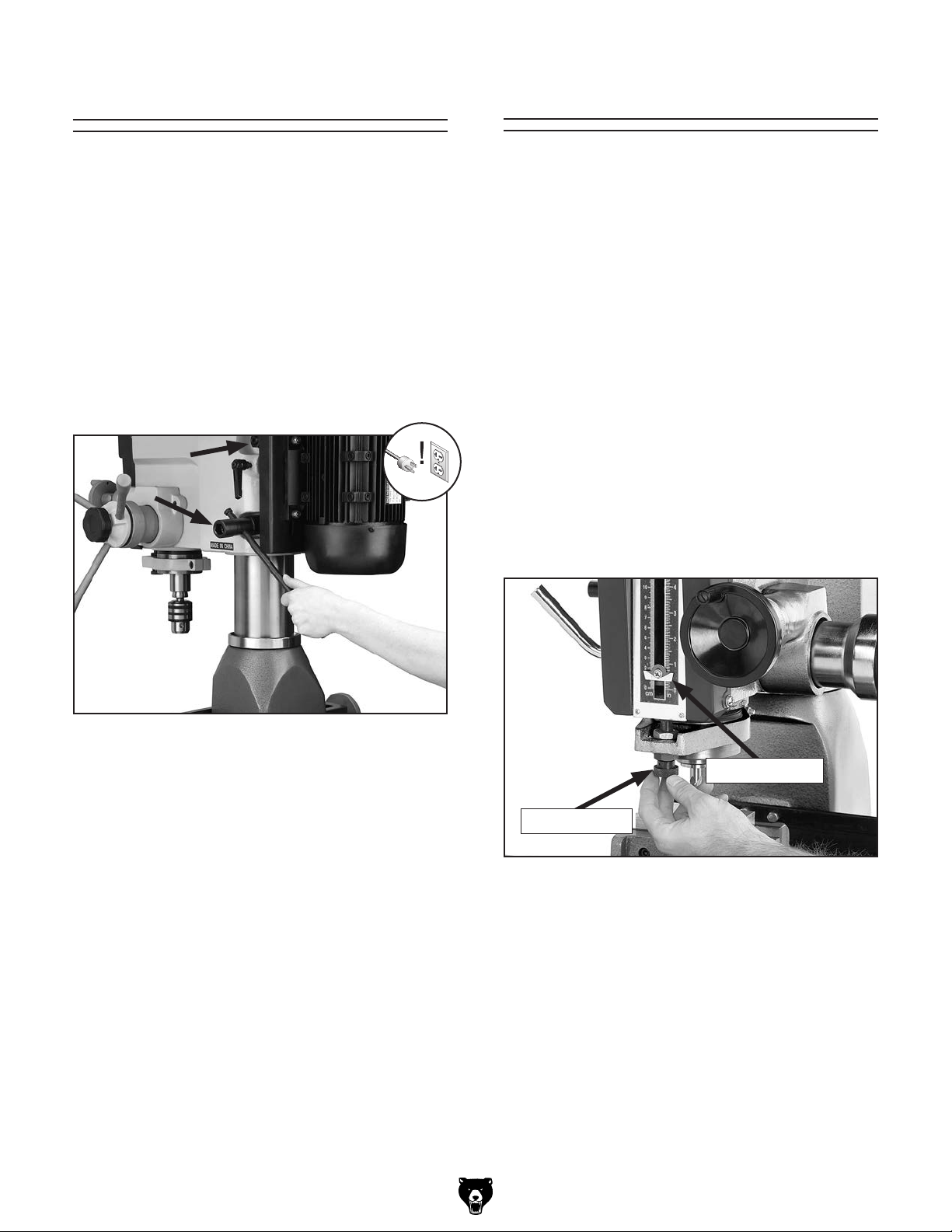
Headstock Position
Depth Stop
The headstock height and rotation on the Model
G0705 can be adjusted for various applications.
For increased quill rigidity and reduced vibrations,
which will produce the best results, keep the quill
fully retracted and set the headstock as low as
possible.
To adjust the headstock height:
1. Using the lug wrench provided, loosen the
two headstock locking nuts located on the
right side of the head near the back (Figure
40).
The depth stop is used to limit the range of downward movement by the drill bit or cutter. Maximum
depth is 4
To calibrate the depth stop:
1. Install the cutting tool, then make sure the
2. Turn the knurled knob of the depth stop
11
⁄16".
spindle is drawn all the way up into the head.
To prevent damaging the workpiece, place a
piece of paper on the workpiece. Loosen the
headstock locking nuts and lower the head
until the drill bit or cutter just contacts the
paper. Tighten the headstock locking nuts.
(Refer to Figure 40 for the location of the
headstock locking nuts).
leadscrew until the top of the indicator plate is
level with your desired depth as listed on the
scale to the left or right (Figure 41).
Figure 40. Headstock locking nuts.
2. Use the head crank to move the head up
or down, and rotate the headstock by hand
according to your needs.
3. Tighten the two head locking nuts.
Indicator Plate
Knurled Knob
Figure 41. Typical setting of depth stop.
-34-
Model G0705 (Mfg. since 09/09)
Page 39

Table Travel
The mill/drill table moves in the longitudinal
(X-axis) and cross (Y-axis) directions.
Longitudinal Feed
The handwheels shown in Figure 42 at each
end of the table move the table longitudinally
(X-axis). These handwheels will move the table in
both directions. One complete revolution of either
handwheel moves the longitudinal feed 0.100". A
scale on the front of the table is used when a high
tolerance is not required. The table locks located
on the front of the table, shown in Figure 43 lock
the table in position longitudinally. Use these
when performing operations that only require
cross slide movement.
Longitudinal Handwheels
Cross Feed
The cross handwheel shown in Figure 42 move
the table along the cross axis (Y- a xis). One
complete revolution of the handwheel moves the
cross slide 0.100". The table lock lever located
on the right side of the cross slide underneath
the table, shown in Figure 43 locks the table in
the cross direction. Use his lock when performing operations that only require longitudinal table
movement.
Graduated Dials
The graduated dials (Figure 44) on the handwheels
for the table and fine feed can be indexed or
“zeroed” to help make accurate and convenient
movements. Each dial can be reset or locked with
the thumbscrew attached to it.
Example:
Suppose you want to drill a series of holes in a
workpiece at 0.625" centers. After locating and
drilling the first placement, you can set the dial
of the appropriate axis to zero while holding
the handwheel. Move the table 0.625". Drill the
next hole and proceed as above.
Cross Handwheel
Figure 42. Table X- and Y-axis controls.
X-Axis Table Lock Levers
X-Axis Scale
Y-Axis Table Lock Lever
Figure 43. Table locks and scales.
Thumb
Screw
Figure 44. Graduated dial.
Graduated Dial
Handwheel
Model G0705 (Mfg. since 09/09)
-35-
Page 40

ACCESSORIES
SECTION 5: ACCESSORIES
H2689—R-8 Quick Change Collet Set
An affordable quick change collet system with ultra
precision. These spring collets are hardened and
ground to exacting tolerances and offer incredible
holding power. This set includes an R-8 arbor and
nut, spanner wrench, plastic carrying case and
collets sized
What's more, the nut features a self-ejecting rim!
A set like this will truly speed up any tool changing
process. Drawbar size is
Figure 45. H2689 R-8 Quick Change Collet Set.
G9299—10" Yuasa-Type Rotary Table
This high precision rotary table features extra
deep coolant channels, dual positive action locks,
very low profiles, 10 second vernier scales, gear
drives with oil immersion and satin chrome dials.
See the current Grizzly catalog for full specifications. Features: 4.330" overall height (horizontal),
6.750" height to center hole (vertical), #3 Morse
Taper, 0.465" T-slot width, and 117 lb approximate
shipping weight.
1
⁄8", 1⁄4", 3⁄8", 1⁄2 ", 5⁄8", 3⁄4", 7⁄8", and 1".
7
⁄16" - 20.
G1076—52-PC. Clamping Kit
This clamping kit includes 24 studs, six step block
pairs, six T-nuts, six flange nuts, four coupling
nuts, and six end hold-downs. The rack is slotted
so it can be mounted close to the machine for
easy access.
Figure 47. G1076 52-PC. Clamping Kit.
G9324—Boring Head Combo Set
Hardened and ground adjusting screws along
with a wide base design guarantee a long life and
trouble-free use. Includes a 3" boring head, R-8
shank with 1
bar set.
1
/2"-18 TPI, and a 12 piece 3/4" boring
Figure 46. G9299 10" Yuasa-Type Rotary Table.
-36-
Figure 48. G9324 Boring Head Combo Set.
Model G0705 (Mfg. since 09/09)
Page 41

G2861—Face Mill
G4051—Carbide Insert for Face Mill
1
This 2
/2" Face Mill accepts four carbide inserts
(not included). Comes with an R-8 arbor.
Figure 49. G2861 Face Mill.
G5641—1-2-3 Blocks
G9815—Parallel Set
H5556—Edge Finder Set
G5641
H5556
G9815
G9760—20-PC. 2 & 4 Flute TiN End Mill Set.
Includes these sizes and styles in two and four
3
flute styles:
3
/8", 11/16", and 3/4".
/16", 1/4", 5/16", 3/8", 7/16", 1/2", 9/16", 5/8",
Figure 50. G9760 20-PC End Mill Set.
G9765—9-PC. Ball End Mill Set
Features 2 flute ball nose end mills. Includes the
following sizes:
3
/4".
and
1
/8", 3/16", 1/4", 5/16", 3/8", 7/16", 1/2", 5/8"
Figure 52. G5641 1-2-3 Blocks, G9815 Parallel
Set, and H5556 Edge Finder Set.
H8370—Power Feed for Mills
If you want to get the most out of your mill, you
really need a power feed. This power feed comes
with everything required to start milling with exact
control. Comes supplied with a mounting bracket,
gear, auto-stop limit switch with moveable stop
pins, gear guard, and motor. Specs: 0–140 RPM,
200 RPM rapid switch, 440 in/lb. maximum torque,
110V 60Hz motor, 4:1 bevel drive gear.
Figure 51. G9765 9 PC. Ball End Mill Set.
Model G0705 (Mfg. since 09/09)
Figure 53. H8370 Power Feed.
-37-
Page 42

SECTION 6: MAINTENANCE
Cleaning and
Always disconnect power
to the machine before
performing maintenance.
Failure to do this may
result in serious personal injury.
Schedule
For optimum performance from your machine,
follow this maintenance schedule and refer to any
specific instructions given in this section.
Daily Check:
• Make sure mill/drill is disconnected from
power when not in use.
• Check for loose mounting bolts.
• Make sure mill/drill is clean and lubricated.
• Check for worn or damaged wires.
• Check for any other unsafe condition.
Protecting
Metal chips left on the machine that have been
soaked with water-based coolant will invite oxidation and a gummy residue buildup around the
moving parts. Use a brush and shop vacuum to
remove chips and debris from the working surfaces of the mill. Never blow off the mill with compressed air, as this will force metal chips deep into
the mechanisms and may cause injury to yourself
or bystanders.
Remove any rust build-up from unpainted cast
iron surfaces of your mill and treat them with a
non-staining lubricant after cleaning.
Keep unpainted cast iron surfaces rust-free with
regular applications of products like G96
Treatment, SLIPIT
Grizzly catalog or website).
®
, or Boeshield® T-9 (see the
®
Gun
Monthly Check:
• Check that gibs are adjusted properly.
Biannual Check:
• Lubricate table leadscrews.
-38-
Model G0705 (Mfg. since 09/09)
Page 43
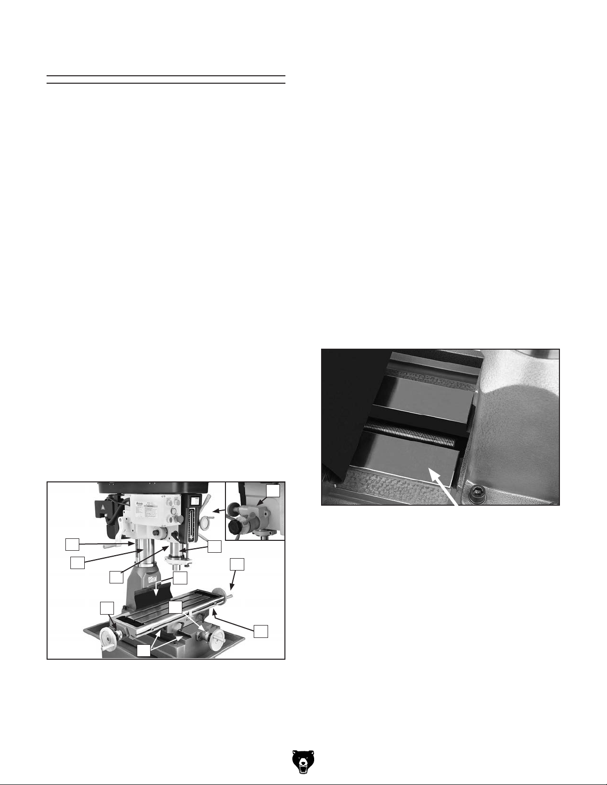
Lubrication
Points requiring periodic lubrication are:
A. Column. A light film of oil (Mobil Vactra 2 or
ISO 68 equivalent) will smooth action and
prevent rust and corrosion.
B. Column Rack. Lubricate every 90 days with
NLGI #2 grease.
Table Leadscrews
Every six months, or more frequently under heavy
use, clean and lubricate the leadscrews.
Items Needed: Qty
Mobil Vactra 2 or ISO 68 Equivalent ................. 1
Stiff-Bristled Nylon Brush for Cleaning .............. 1
Mineral Spirits ................. As needed for cleaning
Shop Rags ...................... As needed for cleaning
To lubricate the leadscrews:
C. Quill. A light coating of oil (Mobil Vactra 2)
will ensure smooth movement.
D. Quill Rack. Lubricate every 90 days with
NLGI #2 grease.
E. Table Leadscrews. Lubricate once each
week with several drops of Mobil Vactra 2 or
way oil. Refer to Table Leadscrews on this
page for more information on this procedure.
F. Ball Oilers. Wipe the outer surface of the ball
fitting with a clean cloth to remove contaminants. Press the ball of the fitting with the tip
of the oiler. Press a few drops of Mobil Vactra
2 or way oil into the ball fitting, then clean up
any residue with a cloth.
G. Ways. Periodically lubricate the ways with
Mobil Vactra 2 or way oil.
F
1. DISCONNECT MILL/DRILL FROM POWER!
2. Using the cross handwheel, move the table
as far forward as possible.
3. Lift or remove the rubber way cover, then use
mineral spirits and a brush to clean as much
of the existing oil and debris as possible off
of the cross travel leadscrew shown in Figure
55. Allow the leadscrew to dry.
B
A
D
F
G
Figure 54. Ball oiler locations.
Model G0705 (Mfg. since 09/09)
E
F
Figure 55. Cross travel leadscrew location.
C
F
E
4. Apply oil to the exposed leadscrew threads,
then move the table through its full range of
cross motion several times to disperse the oil
along the full length of the leadscrew.
-39-
Page 44

5. Using the longitudinal handwheel, move the
table as far to one side as possible.
V-Belts
6. Use mineral spirits and a brush to clean as
much of the oil and debris as possible off of
the longitudinal leadscrew shown in Figure
56. Allow the leadscrew to dry.
Figure 56. Longitudinal leadscrew location.
7. Apply oil to the exposed leadscrew threads,
then move the table through its full range of
longitudinal motion several times to disperse
the oil along the full length of the leadscrew.
Inspect regularly for tension and wear. Refer to
Figure 57 for proper belt tension. Belt deflection should be approximately
pressure. Replacement V-belts can be found in
the back of this manual in the part breakdowns.
Check pulleys to ensure that they are properly
aligned when installing V-belts.
To replace the V-belts, refer to Speed Changes
on Page 29 to loosen the belts. Remove them
from the pulleys, then install new V-belts.
1
⁄4"
Deflection
1
⁄4" under moderate
Pulley
Pulley
Figure 57. Belt tension.
-40-
Model G0705 (Mfg. since 09/09)
Page 45

Troubleshooting
SECTION 7: SERVICE
Review the troubleshooting and procedures in this section to fix or adjust your machine if a problem develops. If you need replacement parts or you are unsure of your repair skills, then feel free to call our Technical
Support at (570) 546-9663.
Troubleshooting
Symptom Possible Cause Possible Solution
Machine does not
start.
Machine stalls or is
overloaded.
1. Wall fuse/circuit breaker is blown/tripped.
2. Plug at fault or wired incorrectly.
3. Motor wired incorrectly.
4. Wiring is open/has high resistance.
5. Machine power switch is at fault.
6. Motor is at fault.
1. Feed rate too fast/cutting speed too slow.
2. Wrong cutter type.
3. Machine is undersized for the task or
tooling is incorrect for the task.
4. Motor connection is wired incorrectly.
5. Motor has overheated.
1. Ensure circuit size is correct and a short does not
exist. Reset breaker or replace fuse.
2. Ensure plug is not damaged and is wired correctly.
3. Ensure motor wiring is correct.
4. Check for broken wires or disconnected/corroded
connections; repair/replace as necessary.
5. Ensure switch is wired correctly; replace if at fault.
6. Test/repair/replace.
1. Adjust feed rate/cutting speed.
2. Use the correct cutter for the task.
3. Use smaller or sharper tooling; reduce feed rate or
spindle speed; use cutting fluid if possible.
4. Wire motor correctly for the intended voltage.
5. Clean off motor, let cool, and reduce workload.
Machine has
vibration or noisy
operation.
6. Motor bearings are at fault.
t7. Motor is at fault.
1. Motor or machine component is loose.
2. Excessive depth of cut.
3. Cutter/tooling is loose.
4. Cutter is dull or at fault.
5. Bit is chattering.
6. Quill is overextended.
7. Machine is incorrectly mounted or sits
unevenly.
8. Motor bearings are at fault.
6. Test by rotating shaft; rotational grinding/loose shaft
requires bearing replacement.
7. Test/repair/replace motor.
1. Inspect/replace stripped or damaged bolts/nuts, and
re-tighten with thread locking fluid.
2. Decrease depth of cut.
3. Make sure tooling is properly secured.
4. Replace/resharpen cutter.
5. Replace/sharpen bit; index bit to workpiece; use
appropriate feed rate and cutting RPM (Page 29).
6. Retract quill, then lower headstock.
7. Tighten/replace mounting bolts in bench; relocate/
shim machine.
8. Test by rotating shaft; rotational grinding/loose shaft
requires bearing replacement.
Model G0705 (Mfg. since 09/09)
-41-
Page 46

Symptom Possible Cause Possible Solution
Tool slips in collet. 1. Collet is not fully drawn up into
spindle taper.
2. Wrong size collet.
3. Debris on collet or in spindle taper.
4. Taking too big of a cut.
5. Making a climb cut.
Breaking tools or cutters. 1. Spindle speed is too slow/feed rate
is too fast.
2. Cutting tool getting too hot.
3. Taking too big of a cut.
4. Spindle extended too far down.
Workpiece vibrates or
chatters during operation.
Table is hard to move. 1. Table locks are tightened down.
Bad surface finish. 1. Spindle speed is too slow/feed rate
1. Table locks not tight.
2. Quill lock lever not tight.
3. Workpiece not securely clamped to
table or into mill vice.
4. Spindle speed is too slow/feed rate
is too fast.
5. Spindle extended too far down.
2. Chips have loaded up on ways.
3. Ways are dry and need lubrication.
4. Table limit stops are interfering.
5. Gibs are too tight.
is too fast.
2. Using a dull or incorrect cutting tool.
3. Wrong direction of rotation of cutting
tool.
4. Workpiece not securely clamped.
5. Spindle extended too far down.
1. Tighten drawbar.
2. Measure tool shank diameter and match with
appropriate diameter collet.
3. Clean collet and spindle taper.
4. Lessen depth of cut and allow chips to clear.
5. Reverse feed direction to avoid climb cuts.
1. Set spindle speed correctly (Page 29) or use a
slower feed rate.
2. Use coolant fluid or oil for appropriate application.
3. Decrease depth of cut.
4. Fully retract spindle and lower headstock. This
increases rigidity.
1. Tighten down table locks (Page 35).
2. Tighten quill lock lever (Page 31).
3. Check that clamping is tight and sufficient for the
job. Make sure mill vice is tight to the table.
4. Set spindle speed correctly (Page 29) or use a
slower feed rate.
5. Fully retract spindle and lower headstock. This
increases rigidity.
1. Make sure table locks are fully released.
2. Frequently clean away chips that load up during
milling operations.
3. Lubricate ways and handles (Page 39).
4. Check to make sure that all table limit stops are not
in the way.
5. Adjust gibs (see Page 43).
1. Set spindle speed correctly (Page 29) or use a
slower feed rate.
2. Sharpen cutting tool or select one that better suits
the operation.
3. Check for proper direction of cutting rotation for
cutting tool.
4. Secure properly to the table.
5. Fully retract spindle and lower headstock. This
increases rigidity.
-42-
Model G0705 (Mfg. since 09/09)
Page 47

Gibs
Gibs are wedge-shaped pieces of metal that fill the
gap between the dovetailed ways of the machine.
By adjusting the position of the gib in the gap, you
can remove any play that might exist between the
adjacent components. The gibs are pre-adjusted
at the factory but due to storage, break-in, and
usage, they may require adjustment.
Tools Needed Qty
Standard #2 Screwdriver ................................... 1
To adjust the table gibs:
1. DISCONNECT MILL/DRILL FROM POWER!
2. Loosen the table travel locks.
3. Loosen or tighten the cross gib screws
(Figure 58) in an alternating manner to adjust
the cross travel gib.
The table should slide smoothly in the cross
direction with no play or looseness. Do not
overtighten the gibs or premature slide and
gib wear will occur.
Return Spring
The tail end of the spring is located on
the perimeter of the spring housing. This
part may be sharp! Use leather gloves or
a heavy shop towel to cover the tail while
loading or unloading return spring pressure. Failure to use such precautions may
result in personal injury. Do not completely
remove the cover! If you remove the spring
cover, the spring will uncoil rapidly and
create a risk of laceration or impact injury.
Wear gloves and safety glasses during this
procedure.
The spring tension for automatic quill recoil has
been pre-set at the factory. It should not need
adjustment under most normal circumstances. If
it does need adjustment, the spring housing is
located on the left side of the head.
To adjust the spring tension:
1. DISCONNECT MACHINE FROM POWER!
2nd Longitudinal
Gib Screw Location
Cross Gib Screw
(1 of 2 shown)
Figure 58. Table gib adjustment screw locations.
4. Lubricate the cross way and gib.
5. Repeat the process for the longitudinal way
gib using the longitudinal gib screws on the
left and right sides of the table base.
2nd Cross Gib
Screw Location
Longitudinal Gib
Screw (1 of 2 shown)
2. PUT ON SAFETY GLASSES!
3. Loosen the black thumb knob shown in
Figure 59 two or three turns. DO NOT com-
pletely remove the thumb knob.
Spring Cover
Roll Pin
Thumb Knob
Figure 59. Spring cover.
Model G0705 (Mfg. since 09/09)
-43-
Page 48

4. Put on gloves and pull the spring cover out
enough so the notches just clear the roll pin.
HOLD THE SPRING COVER TIGHTLY or
the force of the spring will spin it out of your
hands.
5. Rotate the cover to adjust the tension. Push
the cover back in to engage the roll pin in one
of the notches, as shown in Figure 60.
Notch
Tools Needed Qty
3mm Hex Bit ...................................................... 1
6" Extension for Hex Bit .................................... 1
Ratchet for Hex Bit ............................................ 1
To adjust the X-axis leadscrew:
1. Locate the X-axis leadscrew adjuster shown
in Figure 61 under the middle of the table.
The head on the adjustment screw faces to
the right.
Leadscrew Adjuster
Figure 60. Adjusting spring tension.
6. Tighten the black thumb knob.
Leadscrew Backlash
When you turn the handwheels to adjust the position of the table, you will notice slight play (backlash) in the handwheel before the table begins to
move. If this play is greater than 0.008" (measured
with the dial at the base of each handwheel), then
you will need to adjust the leadscrews.
Make adjustments in small increments. Overtightening to attempt to reduce backlash to less
than 0.003" is impractical and will add unnecessary wear to both the leadscrews and the adjusters.
Figure 61. X-axis leadscrew adjuster.
2. Tighten the adjustment screw.
3. Test the adjustment by turning one of the side
handwheels. You should detect less than
0.008" of play.
To adjust the Y-axis leadscrew:
1. Locate the adjuster midway along the
Y-access leadscrew, inside the base. This
adjuster can be accessed by reaching under
the way cover just behind the table.
2. Tighten the adjustment screw and test the
adjustment in the same manner as you did for
the X-axis leadscrew.
-44-
Model G0705 (Mfg. since 09/09)
Page 49

SECTION 8: WIRING
These pages are current at the time of printing. However, in the spirit of improvement, we may make changes to the electrical systems of future machines. Study this section carefully. If there are differences between
your machine and what is shown in this section, call Technical Support at (570) 546-9663 for assistance
BEFORE making any changes to the wiring on your machine.
Wiring Safety Instructions
SHOCK HAZARD. Working on wiring that is connected to a power source is extremely dangerous.
Touching electrified parts will result in personal
injury including but not limited to severe burns,
electrocution, or death. Disconnect the power
from the machine before servicing electrical components!
MODIFICATIONS. Modifying the wiring beyond
what is shown in the diagram may lead to unpredictable results, including serious injury or fire.
This includes the installation of unapproved aftermarket parts.
WIRE CONNECTIONS. All connections must
be tight to prevent wires from loosening during
machine operation. Double-check all wires disconnected or connected during any wiring task to
ensure tight connections.
CIRCUIT REQUIREMENTS. You MUST follow
the requirements at the beginning of this manual when connecting your machine to a power
source.
WIRE/COMPONENT DAMAGE. Damaged wires
or components increase the risk of serious personal injury, fire, or machine damage. If you notice
that any wires or components are damaged while
performing a wiring task, replace those wires or
components.
MOTOR WIRING. The motor wiring shown in
these diagrams is current at the time of printing
but may not match your machine. If you find this
to be the case, use the wiring diagram inside the
motor junction box.
CAPACITORS/INVERTERS. Some capacitors
and power inverters store an electrical charge for
up to 10 minutes after being disconnected from
the power source. To reduce the risk of being
shocked, wait at least this long before working on
capacitors.
EXPERIENCING DIFFICULTIES. If you are experiencing difficulties understanding the information
included in this section, contact our Technical
Support at (570) 546-9663.
The photos and diagrams
included in this section are
best viewed in color. You
can view these pages in
color at www.grizzly.com.
Model G0705 (Mfg. since 09/09)
-45-
Page 50

Ground
110V Terminal
Block Jumper
Position.
(Wire positions
are the same for
110V/220V)
U1
Z2
W2
V1
U2
Z1
V2
W1
G0705 Wiring Diagram
Motor 220V
U1
Run
Capacitor
20 MFD
450 VAC
U2
V1
W1
Z2
W2
V1
U2
Z1
V2
V2
U1
PE
Start
Capacitor
150 MFD
250 VAC
To Electrical Box
Cord Rewired for 110V
Neutral
Hot
Ground
110 VAC
5-20 Plug
(As Recommended)
To Electrical Box
Ground
G
Hot
Hot
6-15 Plug
(As Recommended)
-46-
Model G0705 (Mfg. since 09/09)
Page 51

GND
GND
Contactor Information
G0705 Wiring Diagram (Continued)
For 220V, Contactor Type 3TB41 22-OX, Coil Voltage 220V/60Hz/1PH, SIEMENS
For 110V, Contactor Type 3TB41 22-OX, Coil Voltage 110V/60Hz/1PH, SIEMENS
(Contactor is wired the same for 110V/220V)
To Motor
To Plug
U1
U2
V1
V2
L
L
N
12A
L 1
PE
PE
Electrical Box
FUSE
U1
U2
V1
V2
4
3
L
N
N
PE
13NO
21NC
31NC
CONTACTOR
SIEMENS KM1
43NO
13NO
21NC
31NC
CONTACTOR
SIEMENS KM2
43NO
1L1
3L2
5L3
8
4
4
4
1L1
4
6
3L2
5L3
U2
U2
V1
V1
V2
N
A2
2T1
N
N
A2
2T1
4T2
6T3
4T2
6T3
14NO
22NC
32NC
7
44NO
5
7
14NO
5
22NC
5
32NC
44NO
Control Panel (Viewed From Behind)
Indicator Light Type XDJ2(J) 220V AC
Indicator Light Type XDJ2(J) 110V AC
(Indicator is wired the same for 110V/220V)
N
A1
6
N
L
L
A1
8
L
L
L
Motor
Electrical Box
Figure 62. Electrical component locations.
Model G0705 (Mfg. since 09/09)
7
4
3
REV
4
EMERGENCY
STOP
BUTTON
2
2
5
3
4
FWD
4
POWER
X1
1
1
1
1
INDICATOR
X2
N
3
LAMP
STOP
BUTTON
2
1
2
-47-
Page 52

84
SECTION 9: PARTS
Headstock Parts Breakdown
100
48
49
51
2
102
20
71
29
18
86
9
74
25
32
27
79
26
31
97
28
23-1
35
98
33
94
92
23-2
94
23-4
95
93
97
96
93-4
93-5
93-3
93-1
93-2
23-3
23-5
23-3
113-1
113
13
58
80
64
63
62
89
78
77
76
81
62
65
21
88
75
72
24
23
22
63
52
10
85
83
82
3
4
101
45
46
47
90
91
99
60
59
1
8
-48-
7-1
6
7-2
5
7-3
7
7-2
19
7-4
44
61
43
41
40
61
37
39
42
57
56
55
54
53
17
66
16
68
69
67
70
11-1
11-1
15
11-2
11-5
11
14
12
11-3
11-4
11-6
11-7
Model G0705 (Mfg. since 09/09)
Page 53

Headstock Parts List
REF PART # DESCRIPTION REF PART # DESCRIPTION
1 P0705001 HEAD CASTING 20 P0705020 PINION SHAFT
2 P0705002 DRAWBAR 21 PFH08 FLAT HD SCR 10-24 X 1/2
3 P0705003 SPINDLE LOCK NUT 22 PK25M KEY 7 X 7 X 20
4 P0705004 SPINDLE PULLEY 23 P0705023 DOWNFEED ASSEMBLY
5 P0705005 OUTER BEARING PLATE 23-1 P0705023-1 CASE
6 PCAP04 CAP SCREW 1/4-20 x 1/2 23-2 P0705023-2 WORM SHAFT
7 P0705007 SPINDLE TAPER SLEEVE SET 23-3 P6202ZZ BALL BEARING 6202ZZ
7-1 P0705007-1 SPINDLE TAPER SLEEVE 23-4 PR05M EXT RETAINING RING 15MM
7-2 P6009ZZ BALL BEARING 6009ZZ 23-5 P0705023-5 SPACER 34MM
7-3 P0705007-3 SPACER 74MM 24 PCAP07 CAP SCREW 5/16-18 X 3/4
7-4 PR92M EXT RETAINING RING 41MM 25 P0705025 SLEEVE ASSEMBLY
8 PR50M INT RETAINING RING 80MM 26 P0705026 COMPRESSION SPRING
9 P0705009 RUBBER FLANGE 27 P0705027 LEVER BASE
10 P0705010 QUILL CLAMP 28 P0705028 FEED ADJUST KNOB M10-1.5 X 45
11 P0705011 QUILL ASSEMBLY 29 P0705029 LEVER
11-1 P0705011-1 SPANNER NUT 31 P0705031 WORM SHAFT COVER
11-2 P0705011-2 TOOTHED SPINDLE WASHER 32 PCAP02 CAP SCREW 10-24 X 3/8
11-3 P30206 TAPERED ROLLER BEARING 30206 33 P0705033 MICRO ADJUST INDICATOR SET
11-4 P0705011-4 SPINDLE SLEEVE MT#3 35 P0705035 HANDWHEEL ASSEMBLY
11-5 P30207 TAPERED ROLLER BEARING 30207 37 P0705037 TORSION SPRING BASE
11-6 P0705011-6 SPINDLE SHAFT 39 PCAP33 CAP SCREW 10-24 X 3/4
11-7 P0705011-7 SPINDLE CUP 40 P0705040 TORSION SPRING W/COVER
12 P0705012 DRIFT KEY 41 PLW02 LOCK WASHER 1/4
13 P0705013 CHUCK ARBOR R8-B16 42 PW06 FLAT WASHER 1/4
14 P0705014 CUTTER ARBOR 43 PLW02 LOCK WASHER 1/4
15 P0705015 DEPTH STOP ASSEMBLY 44 P0705044 KNOB BOLT M8-1.25 X 12
16 P0705016 DEPTH STOP ADJUSTER 45 P0705045 WORM SHAFT
17 PCAP159M CAP SCREW 1/4-20 x 2 46 P0705046 WORM SHAFT BUSHING
18 PN05 HEX NUT 1/4-20 47 P0705047 ELEVATION ASSEMBLY
19 P0705019 DEPTH STOP BLOCK
Model G0705 (Mfg. since 09/09)
-49-
Page 54

Headstock Parts List (continued)
REF PART # DESCRIPTION REF PART # DESCRIPTION
48 PCAP05 CAP SCREW 1/4-20 X 3/4 80 P0705080 PULLEY IDLER PLATE
49 P0705049 ELEVATION CRANK 81 PN04 HEX NUT 5/8-11
51 P0705051 CLAMP HANDLE 82 PW07 FLAT WASHER 5/16
52 P0705052 OUTER QUILL CLAMP 83 PCAP08 CAP SCREW 5/16-18 X 1-1/2
53 P0705053 INNER QUILL CLAMP 84 P0705084 IDLER PULLEY
54 P0705054 QUILL CLAMP SPACER 85 PN04 HEX NUT 5/8-11
55 P0705055 QUILL CLAMP HANDLE 86 P0705086 MOTOR PULLEY SET
56 P0705056 SCREW KEY 88 PVA33 V-BELT A33
57 PN08 HEX NUT 3/8-16 89 PVA39 V-BELT A39
58 P0705058 COMPRESSION SPRING 90 P0705090 WIRE CLIP
59 P0705059 BELT TENSION PIN 91 PCAP09 CAP SCREW 5/16-18 X 5/8
60 P0705060 RUBBER PAD 92 P0705092 MOTOR MOUNT PLATE
61 PB46 HEX BOLT 5/8-11 X 6 93 P0705093 MOTOR 2HP 110/220V 1-PH
62 PW14 FLAT WASHER 5/8 93-1 P0705093-1 MOTOR JUNCTION BOX
63 PN04 HEX NUT 5/8-11 93-2 PC150D S CAPACITOR 150M 250V 1-5/8 X 3-1/4
64 P0705064 HEADSTOCK WRENCH 93-3 PC20B R CAPACITOR 20M 450V 1-5/8 X 3-1/4
65 P0705065 LOCK HANDLE M8-1.25 X 25 93-4 P0705093-4 MOTOR FAN
66 P0705066 FRONT COVER PLATE ASSEMBLY 93-5 P0705093-5 MOTOR FAN COVER
67 PCAP04 CAP SCREW 1/4-20 X 1/2 94 PW07 FLAT WASHER 5/16
68 P0705068 LIMIT PLATE 95 PB03 HEX BOLT 5/16-18 X 1
69 PW18 FLAT WASHER #5 96 PN02 HEX NUT 5/16-18
70 PS50 PHLP HD SCR 5-40 X 1/4 97 PB36 HEX BOLT 7/16-14 X 3/4
71 P0705071 BELT COVER 98 PK109M KEY 7 X 7 X 35
72 P0705072 LOWER BELT PLATE 99 P0705099 GUARD BRACKET
74 P0705074 SPINDLE COVER 100 PCAP03M CAP SCREW M5-.8 X 8
75 PCAP158M CAP SCREW M3-.5 X 16 101 PCAP26M CAP SCREW M6-1 X 12
76 PW07 FLAT WASHER 5/16 102 P0705102 PROTECTIVE PLATE
77 PB32 HEX BOLT 5/16-18 X 5/8 113 P0705113 CHUCK B16 1–13MM
78 PCAP04 CAP SCREW 1/4-20 X 1/2 113-1 P0705113-1 CHUCK KEY
79 P0705079 SPEED CHART
-50-
Model G0705 (Mfg. since 09/09)
Page 55

Base Parts Breakdown
241
242
236
240
238
237
226
205
206
212
209
245
201
206
205
213
211
210
246
202
203
204
219
205
234
207
218
232
217
216
212
226
244
221
220
222
225
228
243
230
205
227
228
223
244
219
227
224
218
217
231
247
235
212
205
207
233
207
Model G0705 (Mfg. since 09/09)
229
-51-
Page 56

Base Parts List
REF PART # DESCRIPTION REF PART # DESCRIPTION
201 P0705201 TABLE 226 PB09 HEX BOLT 5/16-18 X 1/2
202 P0705202 T-NUT 1/4-20 227 P0705227 GIB SCREW
203 P0705203 TABLE STOP 228 P0705228 LOCK HANDLE SPACER
204 PCAP04 CAP SCREW 1/4-20 X 1/2 229 P0705229 LOCK HANDLE M8-1.25 X 32
205 PLUBE001 TAP-IN BALL OILER 8MM 230 P0705229 LOCK HANDLE M8-1.25 X 32
206 P0705206 TABLE HANDWHEEL 231 PCAP03 CAP SCREW 5/16-18 X 1
207 P0705207 HANDLE 232 PCAP107 CAP SCREW 5/16-18 X 2-1/4
209 P0705209 HANDWHEEL COLLAR 233 P0705233 CROSS HALF NUT
210 P0705210 DOWEL PIN 234 P0705234 BASE
211 P0705211 LEFT FLANGE 235 P0705235 CROSS LEADSCREW ASSEMBLY
212 PCAP03 CAP SCREW 5/16-18 X 1 236 P0705236 COLUMN BASE
213 P0705213 LONGITUDINAL HALF NUT 237 P0705237 ELEVATION RACK
216 P0705216 LONGITUDINAL LEADSCREW 238 P0705238 COLUMN CAP
217 P0705217 KNURLED THUMBSCREW M5-.8 X 12 240 P0705240 COLUMN RING
218 P0705218 INDICATOR PLATE 241 PB64 HEX BOLT 5/8-11 X 2-1/2
219 P0705219 RIVET 2MM 242 PLW06 LOCK WASHER 5/8
220 P0705220 SADDLE 243 PCAP07 CAP SCREW 5/16-18 X 3/4
221 P0705221 DUST COVER PLATE 244 PLW01 LOCK WASHER 5/16
222 P0705222 DUST COVER 245 P0705245 DRAIN PLUG
223 P0705223 LONGITUDINAL GIB 246 P0705246 HEX BOLT M10-1.5 X 140
224 P0705224 CROSS GIB 247 P0705247 CABINET ASSEMBLY
225 P0705225 TABLE CENTER STOP
-52-
Model G0705 (Mfg. since 09/09)
Page 57
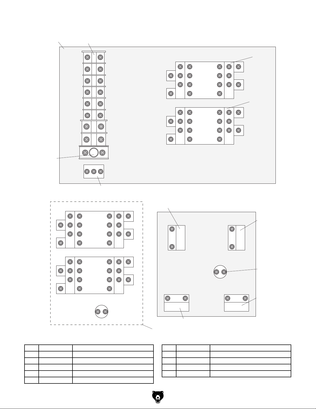
301
302
311
Electrical Components Breakdown & List
303
1L1
3L2
5L3
3L2
1L1
5L3
A1
303
A1
310
12A
14NO
2T1
22NC
4T2
32NC
6T3
4T2
6T3
44NO
14NO
22NC
32NC
44NO
A2
2T1
A2
13NO
21NC
31NC
CONTACTOR
43NO
SIEMENS KM1 220V
13NO
21NC
31NC
CONTACTOR
43NO
SIEMENS KM2 220V
A2
2T1
A2
2T1
4T2
6T3
4T2
6T3
POWER
INDICATOR
LAMP 110V
14NO
22NC
32NC
44NO
14NO
22NC
32NC
44NO
309
13NO
21NC
31NC
CONTACTOR
43NO
SIEMENS KM1 110V
13NO
21NC
31NC
CONTACTOR
43NO
SIEMENS KM2 110V
X1
1L1
3L2
5L3
1L1
3L2
5L3
X2
Electrical Box
308
A1
Control Panel (Viewed From Behind)
304
4
3
A1
REVERSE
BUTTON
POWER
X1
INDICATOR
LAMP 220V
EMERGENCY
STOP
BUTTON
2
1
X2
3
4
FORWARD
BUTTON
STOP
BUTTON
2
1
305
306
307
REF PART # DESCRIPTION REF PART # DESCRIPTION
301 P0705301 ELECTRICAL BOX ASSEMBLY 307 P0705307 EMERGENCY STOP BUTTON
302 P0705302 TERMINAL BLOCK ASSEMBLY 308 P0705308 REVERSE BUTTON
303 P0705303 CONTACTOR SIEMENS 3TB41 220V 309 P0705309 GROUNDING BLOCK
304 P0705304 FORWARD BUTTON 310 P0705310 FUSE 12A
305 P0705305 POWER INDICATOR LAMP 220V 311 P0705311 CONVERSION KIT 110V FOR G0705
306 P0705306 STOP BUTTON
Model G0705 (Mfg. since 09/09)
-53-
Page 58
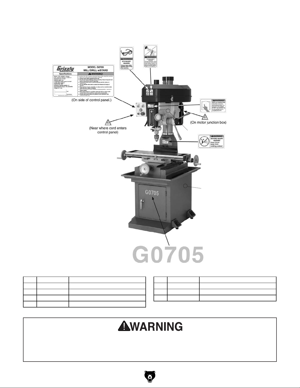
Labels Breakdown and List
401
405
402
403
404
405
406
407
408
409
REF PART # DESCRIPTION REF PART # DESCRIPTION
401 P0705401 MACHINE ID LABEL 406 PPAINT-11 PUTTY TOUCH UP PAINT
402 PLABEL-11B SAFETY GLASSES LABEL 407 P0705407 CUTTER WARNING LABEL
403 PLABEL-55A ENTANGLEMENT LABEL 408 PPAINT-1 GREEN TOUCH UP PAINT
404 PLABEL-12C READ MANUAL LABEL 409 P0705409 MODEL NUMBER LABEL
405 PLABEL-14A ELECTRICITY LABEL
Safety labels warn about machine hazards and ways to prevent injury. The owner of this machine
MUST maintain the original location and readability of the labels on the machine. If any label is
removed or becomes unreadable, REPLACE that label before using the machine again. Contact
Grizzly at (800) 523-4777 or www.grizzly.com to order new labels.
-54-
Model G0705 (Mfg. since 09/09)
Page 59

WARRANTY CARD
Name _____________________________________________________________________________
Street _____________________________________________________________________________
City _______________________ State _________________________ Zip _____________________
Phone # ____________________ Email _________________________________________________
Model # ____________________ Order # _______________________ Serial # __________________
The following information is given on a voluntary basis. It will be used for marketing purposes to help us develop
better products and services. Of course, all information is strictly confidential.
1. How did you learn about us?
____ Advertisement ____ Friend ____ Catalog
____ Card Deck ____ Website ____ Other:
2. Which of the following magazines do you subscribe to?
____ Cabinetmaker & FDM
____ Family Handyman
____ Hand Loader
____ Handy
____ Home Shop Machinist
____ Journal of Light Cont.
____ Live Steam
____ Model Airplane News
____ Old House Journal
____ Popular Mechanics
3. What is your annual household income?
____ $20,000-$29,000 ____ $30,000-$39,000 ____ $40,000-$49,000
____ $50,000-$59,000 ____ $60,000-$69,000 ____ $70,000+
CUT ALONG DOTTED LINE
4. What is your age group?
____ 20-29 ____ 30-39 ____ 40-49
____ 50-59 ____ 60-69 ____ 70+
5. How long have you been a woodworker/metalworker?
____ 0-2 Years ____ 2-8 Years ____ 8-20 Years ____20+ Years
6. How many of your machines or tools are Grizzly?
____ 0-2 ____ 3-5 ____ 6-9 ____10+
____ Popular Science
____ Popular Woodworking
____ Precision Shooter
____ Projects in Metal
____ RC Modeler
____ Rie
____ Shop Notes
____ Shotgun News
____ Today’s Homeowner
____ Wood
____ Wooden Boat
____ Woodshop News
____ Woodsmith
____ Woodwork
____ Woodworker West
____ Woodworker’s Journal
____ Other:
7. Do you think your machine represents a good value? _____ Yes _____No
8. Would you recommend Grizzly Industrial to a friend? _____ Yes _____No
9. Would you allow us to use your name as a reference for Grizzly customers in your area?
Note: We never use names more than 3 times. _____ Yes _____No
10. Comments: _____________________________________________________________________
_________________________________________________________________________________
_________________________________________________________________________________
_________________________________________________________________________________
Page 60

FOLD ALONG DOTTED LINE
FOLD ALONG DOTTED LINE
Place
Stamp
Here
GRIZZLY INDUSTRIAL, INC.
P.O. BOX 2069
BELLINGHAM, WA 98227-2069
Send a Grizzly Catalog to a friend:
Name_______________________________
Street_______________________________
City______________State______Zip______
TAPE ALONG EDGES--PLEASE DO NOT STAPLE
Page 61

WARRANTY AND RETURNS
We shall in no event be liable for death, injuries to persons or property or for incidental, contingent, special,
WARRANTY AND RETURNS
Grizzly Industrial, Inc. warrants every product it sells for a period of 1 year to the original purchaser from
the date of purchase. This warranty does not apply to defects due directly or indirectly to misuse, abuse,
negligence, accidents, repairs or alterations or lack of maintenance. This is Grizzly’s sole written warranty
and any and all warranties that may be implied by law, including any merchantability or fitness, for any particular purpose, are hereby limited to the duration of this written warranty. We do not warrant or represent
that the merchandise complies with the provisions of any law or acts unless the manufacturer so warrants.
In no event shall Grizzly’s liability under this warranty exceed the purchase price paid for the product and
any legal actions brought against Grizzly shall be tried in the State of Washington, County of Whatcom.
or consequential damages arising from the use of our products.
To take advantage of this warranty, contact us by mail or phone and give us all the details. We will then
issue you a “Return Number,’’ which must be clearly posted on the outside as well as the inside of the
carton. We will not accept any item back without this number. Proof of purchase must accompany the
merchandise.
The manufacturers reserve the right to change specifications at any time because they constantly strive to
achieve better quality equipment. We make every effort to ensure that our products meet high quality and
durability standards and we hope you never need to use this warranty.
Please feel free to write or call us if you have any questions about the machine or the manual.
Thank you again for your business and continued support. We hope to serve you again soon.
Page 62

 Loading...