

Page 1

MODEL G0654
6" JOINTER w/ MOBILE BASE
OWNER'S MANUAL
COPYRIGHT © JANUARY, 2008 BY GRIZZLY INDUSTRIAL, INC. REVISED JUNE, 2013 (DM)
WARNING: NO PORTION OF THIS MANUAL MAY BE REPRODUCED IN ANY SHAPE
OR FORM WITHOUT THE WRITTEN APPROVAL OF GRIZZLY INDUSTRIAL, INC.
FOR MACHINES MANUFACTURED SINCE 9/07 #BL10265 PRINTED IN CHINA
Page 2

This manual provides critical safety instructions on the proper setup,
operation, maintenance, and service of this machine/tool. Save this
document, refer to it often, and use it to instruct other operators.
Failure to read, understand and follow the instructions in this manual
may result in fire or serious personal injury—including amputation,
electrocution, or death.
The owner of this machine/tool is solely responsible for its safe use.
This responsibility includes but is not limited to proper installation in
a safe environment, personnel training and usage authorization,
proper inspection and maintenance, manual availability and comprehension, application of safety devices, cutting/sanding/grinding tool
integrity, and the usage of personal protective equipment.
The manufacturer will not be held liable for injury or property damage
from negligence, improper training, machine modifications or misuse.
Some dust created by power sanding, sawing, grinding, drilling, and
other construction activities contains chemicals known to the State
of California to cause cancer, birth defects or other reproductive
harm. Some examples of these chemicals are:
• Lead from lead-based paints.
• Crystalline silica from bricks, cement and other masonry products.
• Arsenic and chromium from chemically-treated lumber.
Your risk from these exposures varies, depending on how often you
do this type of work. To reduce your exposure to these chemicals:
Work in a well ventilated area, and work with approved safety equipment, such as those dust masks that are specially designed to filter
out microscopic particles.
Page 3

Table of Contents
INTRODUCTION ............................................... 2
Machine Description ...................................... 2
Contact Info.................................................... 2
Manual Accuracy ........................................... 2
Identification ................................................... 3
Machine Data Sheet ...................................... 4
SECTION 1: SAFETY ....................................... 6
Safety Instructions for Machinery .................. 6
Additional Safety for Jointers ......................... 8
SECTION 2: POWER SUPPLY ........................ 9
SECTION 3: SETUP ....................................... 11
Items Needed for Setup ............................... 11
Unpacking .................................................... 11
Inventory ...................................................... 12
Cleanup ........................................................ 14
Site Considerations ...................................... 15
Assembly ..................................................... 16
Dust Collection ............................................. 22
Setting Outfeed Table Height ...................... 22
Test Run ...................................................... 23
Recommended Adjustments ........................ 23
Tighten V-Belt .............................................. 23
SECTION 5: ACCESSORIES ......................... 32
SECTION 6: MAINTENANCE ......................... 34
Schedule ...................................................... 34
Cleaning ....................................................... 34
Lubrication ................................................... 34
V-Belt ........................................................... 35
SECTION 7: SERVICE ................................... 36
Troubleshooting ........................................... 36
Inspecting Knives ......................................... 38
Setting/Replacing Knives ............................. 38
Calibrating Infeed Table ............................... 40
Setting Fence Stops .................................... 41
Adjusting Gibs .............................................. 42
Wiring Diagram ............................................ 43
Stand Parts Breakdown ............................... 44
Table Parts Breakdown ............................... 46
Fence Parts Breakdown .............................. 48
Label Placement .......................................... 50
WARRANTY AND RETURNS ........................ 53
SECTION 4: OPERATIONS ........................... 24
Operation Safety .......................................... 24
Basic Controls .............................................. 24
Stock Inspection & Requirements................ 26
Squaring Stock............................................. 27
Surface Planing............................................ 28
Edge Jointing ............................................... 29
Bevel Cutting................................................ 30
Rabbet Cutting ............................................. 31
Page 4

INTRODUCTION
We are proud to provide a high-quality owner’s
manual with your new machine!
We
instructions, specifications, drawings, and photographs
contained inside. Sometimes we make mistakes,
but
also
means that
you receive
will be slightly different than what is shown in
the manual
If you find this to be the case, and the difference
between the manual and machine leaves you
confused about a procedure
for an updated version. W
manuals
and
www.grizzly.com
Alternatively, you can call our Technical Support
for help. Before calling, please write down the
Manufacture Date
stamped
into the machine ID label (see below). This information helps us determine if updated documentation is available for your machine.
We stand behind our machines. If you have
any questions or need help, use the information
below to contact us. Before contacting, please get
the serial number and manufacture date of your
machine. This will help us help you faster.
We want your feedback on this manual. What did
you like about it? Where could it be improved?
Please take a few minutes to give us feedback.
Machine Description
We are proud to offer the Model G0654 6" Jointer
with Mobile Base. This machine is part of a growing Grizzly family of fine woodworking machinery.
When used according to the guidelines set forth in
this manual, you can expect years of trouble-free,
enjoyable operation and proof of Grizzly’s commitment to customer satisfaction.
The specifications, drawings, and photographs
illustrated in this manual represent the Model
G0654 when the manual was prepared. However,
owing to Grizzly’s policy of continuous improvement, changes may be made at any time with no
obligation on the part of Grizzly.
For your convenience, we always keep current
Grizzly manuals available on our website at www.
grizzly.com. Any updates to your machine will be
reflected in these manuals as soon as they are
complete. Visit our site often to check for the latest updates to this manual!
Contact Info
Grizzly Technical Support
1203 Lycoming Mall Circle
Muncy, PA 17756
Phone: (570) 546-9663
Email: techsupport@grizzly.com
Manual Accuracy
made every effort to be exact with the
our policy of continuous improvement
sometimes the machine
.
, check our website
e post current
manual updates for free on our website at
.
and Serial Number
Manufacture Date
Serial Number
-2-
Grizzly Documentation Manager
P.O. Box 2069
Bellingham, WA 98227-2069
Email: manuals@grizzly.com
Model G0654 (Mfg. Since 9/07)
Page 5

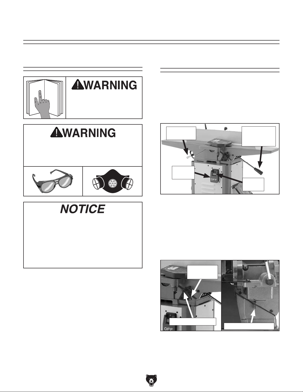
Identification
B
A
P
N
O
C
E
D
F
F
G
H
I
J
Q
M
C
E
K
L
Figure 1. Model G0654 identification.
A. Outfeed Table
B. Fence
C. Fence Tilt Lever
D. Cutterhead Guard
E. Fence Lock
F. Fence Tilt Handle
G. Infeed Table
H. Infeed Table Adjustment Lever
I. ON/OFF Switch
J. Push Block Holder
K. Depth Scale
L. Infeed Table Lock
M. Wheel Assembly
N. Dust Port
O. Outfeed Table Handwheel
P. Outfeed Table Lock
Q. Depth Stop Knob
Model G0654 (Mfg. Since 9/07)
-3-
Page 6

Machine Data Sheet
MACHINE DATA
SHEET
Customer Service #: (570) 546-9663 · To Order Call: (800) 523-4777 · Fax #: (800) 438-5901
MODEL G0654 6" X 46" JOINTER
Product Dimensions:
Weight.............................................................................................................................................................. 231 lbs.
Width (side-to-side) x Depth (front-to-back) x Height............................................................... 46 x 21-1/4 x 37-3/4 in.
Footprint (Length x Width).............................................................................................................. 17-1/8 x 14-1/8 in.
Shipping Dimensions:
Type..................................................................................................................................................... Cardboard Box
Content........................................................................................................................................................... Machine
Weight.............................................................................................................................................................. 236 lbs.
Length x Width x Height....................................................................................................................... 49 x 23 x 16 in.
Must Ship Upright.................................................................................................................................................... No
Electrical:
Power Requirement........................................................................................................... 110V, Single-Phase, 60 Hz
Prewired Voltage.................................................................................................................................................. 110V
Full-Load Current Rating........................................................................................................................................ 14A
Minimum Circuit Size.............................................................................................................................................. 20A
Connection Type....................................................................................................................................... Cord & Plug
Power Cord Included.............................................................................................................................................. Yes
Power Cord Length................................................................................................................................................. 8 ft.
Power Cord Gauge......................................................................................................................................... 14 AWG
Plug Included.......................................................................................................................................................... Yes
Included Plug Type................................................................................................................................................ 5-15
Switch Type............................................................................ ON/OFF Push Button Switch w/Large Shut-Off Paddle
Motors:
Main
Type................................................................................................................. TEFC Capacitor-Start Induction
Horsepower................................................................................................................................................ 1 HP
Phase............................................................................................................................................ Single-Phase
Amps............................................................................................................................................................ 14A
Speed................................................................................................................................................ 3450 RPM
Power Transfer ............................................................................................................................... V-Belt Drive
Bearings..................................................................................................... Shielded & Permanently Lubricated
Main Specifications:
Cutting Capacities
Bevel Jointing............................................................................................................................. 0 – 45 deg. L/R
Maximum Width of Cut................................................................................................................................ 6 in.
Maximum Depth of Cut............................................................................................................................. 1/8 in.
Minimum Workpiece Length........................................................................................................................ 8 in.
Minimum Workpiece Thickness................................................................................................................ 1/2 in.
Maximum Rabbeting Depth...................................................................................................................... 1/2 in.
Number of Cuts Per Minute..................................................................................................................... 14,400
-4-
Model G0654 (Mfg. Since 9/07)
Page 7

Fence Information
Fence Length....................................................................................................................................... 29-3/8 in.
Fence Width........................................................................................................................................ 1-3/16 in.
Fence Height......................................................................................................................................... 4-1/2 in.
Fence Stops............................................................................................................................. 45, 90, 135 deg.
Cutterhead Information
Cutterhead Type...................................................................................................................................... 3 Knife
Cutterhead Diameter............................................................................................................................. 2-1/2 in.
Cutterhead Speed............................................................................................................................. 4800 RPM
Knife Information
Number of Knives............................................................................................................................................. 3
Knife Type............................................................................................................................. HSS, Single-Sided
Knife Length.......................................................................................................................................... 6-1/8 in.
Knife Width............................................................................................................................................... 5/8 in.
Knife Thickness........................................................................................................................................ 1/8 in.
Knife Adjustment........................................................................................................... Jack Screws or Springs
Table Information
Table Length.............................................................................................................................................. 46 in.
Table Width........................................................................................................................................... 7-1/2 in.
Floor to Table Height........................................................................................................................... 33-3/8 in.
Table Adjustment Type..................................................................................................................... Handwheel
Table Movement Type............................................................................................................. Dovetailed Ways
Construction
Base..................................................................................................................................................... Cast Iron
Body Assembly.................................................................................................................................... Cast Iron
Cabinet.................................................................................................................................... Pre-formed Steel
Fence Assembly.................................................................................................................................. Cast Iron
Guard.......................................................................................................................................... Die Cast Metal
Table....................................................................................................................... Precision Ground Cast Iron
Paint........................................................................................................................................... Powder Coated
Other Information
Number of Dust Ports....................................................................................................................................... 1
Dust Port Size.............................................................................................................................................. 4 in.
Mobile Base............................................................................................................................................. Built-In
Other Specifications:
Country Of Origin ............................................................................................................................................... China
Warranty ........................................................................................................................................................... 1 Year
Approximate Assembly & Setup Time ............................................................................................................. 2 Hours
Serial Number Location .................................................................................................. ID Label on Front of Cabinet
ISO 9001 Factory .................................................................................................................................................... No
CSA Certified .......................................................................................................................................................... No
Model G0654 (Mfg. Since 9/07)
-5-
Page 8

SECTION 1: SAFETY
For Your Own Safety, Read Instruction
Manual Before Operating This Machine
The purpose of safety symbols is to attract your attention to possible hazardous conditions.
This manual uses a series of symbols and signal words intended to convey the level of importance of the safety messages. The progression of symbols is described below. Remember that
safety messages by themselves do not eliminate danger and are not a substitute for proper
accident prevention measures. Always use common sense and good judgment.
Indicates an imminently hazardous situation which, if not avoided,
WILL result in death or serious injury.
Indicates a potentially hazardous situation which, if not avoided,
COULD result in death or serious injury.
Indicates a potentially hazardous situation which, if not avoided,
MAY result in minor or moderate injury. It may also be used to alert
against unsafe practices.
This symbol is used to alert the user to useful information about
NOTICE
proper operation of the machine.
Safety Instructions for Machinery
OWNER’S MANUAL. Read and understand this
owner’s manual BEFORE using machine.
TRAINED OPERATORS ONLY. Untrained operators have a higher risk of being hurt or killed.
Only allow trained/supervised people to use this
machine. When machine is not being used, disconnect power, remove switch keys, or lock-out
machine to prevent unauthorized use—especially
around children. Make workshop kid proof!
DANGEROUS ENVIRONMENTS. Do not use
machinery in areas that are wet, cluttered, or have
poor lighting. Operating machinery in these areas
greatly increases the risk of accidents and injury.
MENTAL ALERTNESS REQUIRED. Full mental
alertness is required for safe operation of machinery. Never operate under the influence of drugs or
alcohol, when tired, or when distracted.
ELECTRICAL EQUIPMENT INJURY RISKS. You
can be shocked, burned, or killed by touching live
electrical components or improperly grounded
machinery. To reduce this risk, only allow qualified
service personnel to do electrical installation or
repair work, and always disconnect power before
accessing or exposing electrical equipment.
DISCONNECT POWER FIRST.
nect machine from power supply BEFORE making
adjustments, changing tooling, or servicing machine.
This prevents an injury risk from unintended startup
or contact with live electrical components.
EYE PROTECTION. Always wear ANSI-approved
safety glasses or a face shield when operating or
observing machinery to reduce the risk of eye
injury or blindness from flying particles. Everyday
eyeglasses are NOT approved safety glasses.
Always discon-
-6-
Model G0654 (Mfg. Since 9/07)
Page 9

WEARING PROPER APPAREL. Do not wear
clothing, apparel or jewelry that can become
entangled in moving parts. Always tie back or
cover long hair. Wear non-slip footwear to avoid
accidental slips, which could cause loss of workpiece control.
HAZARDOUS DUST. Dust created while using
machinery may cause cancer, birth defects, or
long-term respiratory damage. Be aware of dust
hazards associated with each workpiece material,
and always wear a NIOSH-approved respirator to
reduce your risk.
HEARING PROTECTION. Always wear hearing protection when operating or observing loud
machinery. Extended exposure to this noise
without hearing protection can cause permanent
hearing loss.
REMOVE ADJUSTING TOOLS. Tools left on
machinery can become dangerous projectiles
upon startup. Never leave chuck keys, wrenches,
or any other tools on machine. Always verify
removal before starting!
USE CORRECT TOOL FOR THE JOB. Only use
this tool for its intended purpose—do not force
it or an attachment to do a job for which it was
not designed. Never make unapproved modifications—modifying tool or using it differently than
intended may result in malfunction or mechanical
failure that can lead to personal injury or death!
AWKWARD POSITIONS. Keep proper footing
and balance at all times when operating machine.
Do not overreach! Avoid awkward hand positions
that make workpiece control difficult or increase
the risk of accidental injury.
CHILDREN & BYSTANDERS. Keep children and
bystanders at a safe distance from the work area.
Stop using machine if they become a distraction.
FORCING MACHINERY. Do not force machine.
It will do the job safer and better at the rate for
which it was designed.
NEVER STAND ON MACHINE. Serious injury
may occur if machine is tipped or if the cutting
tool is unintentionally contacted.
STABLE MACHINE. Unexpected movement during operation greatly increases risk of injury or
loss of control. Before starting, verify machine is
stable and mobile base (if used) is locked.
USE RECOMMENDED ACCESSORIES. Consult
this owner’s manual or the manufacturer for recommended accessories. Using improper accessories will increase the risk of serious injury.
UNATTENDED OPERATION. To reduce the
risk of accidental injury, turn machine OFF and
ensure all moving parts completely stop before
walking away. Never leave machine running
while unattended.
MAINTAIN WITH CARE. Follow all maintenance
instructions and lubrication schedules to keep
machine in good working condition. A machine
that is improperly maintained could malfunction,
leading to serious personal injury or death.
CHECK DAMAGED PARTS. Regularly inspect
machine for any condition that may affect safe
operation. Immediately repair or replace damaged
or mis-adjusted parts before operating machine.
MAINTAIN POWER CORDS. When disconnecting cord-connected machines from power, grab
and pull the plug—NOT the cord. Pulling the cord
may damage the wires inside. Do not handle
cord/plug with wet hands. Avoid cord damage by
keeping it away from heated surfaces, high traffic
areas, harsh chemicals, and wet/damp locations.
GUARDS & COVERS. Guards and covers reduce
accidental contact with moving parts or flying
debris. Make sure they are properly installed,
undamaged, and working correctly.
Model G0654 (Mfg. Since 9/07)
EXPERIENCING DIFFICULTIES. If at any time
you experience difficulties performing the intended operation, stop using the machine! Contact our
Technical Support at (570) 546-9663.
-7-
Page 10

Additional Safety for Jointers
JOINTER INJURY RISKS. Familiarize yourself
with the main injury risks associated with jointers—always use common sense and good judgement to reduce your risk of injury. Main injury
risks from jointers: amputation/lacerations from
contact with the moving cutterhead, entanglement/crushing injuries from getting caught in moving parts, blindness or eye injury from flying wood
chips, or impact injuries from workpiece kickback.
KICKBACK. Know how to reduce the risk of kickback and kickback-related injuries. “Kickback”
occurs during the operation when the workpiece is
ejected from the machine at a high rate of speed.
Kickback is commonly caused by poor workpiece
selection, unsafe feeding techniques, or improper
machine setup/maintenance. Kickback injuries
typically occur as follows: (1) operator/bystanders
are struck by the workpiece, resulting in impact
injuries (i.e., blindness, broken bones, bruises,
death); (2) operator’s hands are pulled into blade,
resulting in amputation or severe lacerations.
GUARD REMOVAL. Except when rabbeting,
never remove guards during operation or while
connected to power. Always replace guard after
rabbeting. You could be seriously injured if you
accidentally touch the spinning cutterhead or
get entangled in moving parts. Before removing
sawdust, turn jointer OFF and disconnect power
before clearing. Immediately replace guards.
DULL/DAMAGED KNIVES/INSERTS. Only use
sharp, undamaged knives/inserts. Dull, damaged
or rusted knives/inserts increase risk of kickback.
OUTFEED TABLE ALIGNMENT. To reduce the
risk of kickback and personal injuries, keep the
outfeed table even with the knives/inserts at top
dead center (the highest point during rotation).
If the outfeed table is set too low, the workpiece
may rock against the cutterhead. If the table is set
too high, the workpiece may hit the outfeed table
and get stuck over the cutterhead.
INSPECTING STOCK. To reduce the risk of
kickback injuries or machine damage, thoroughly
inspect and prepare the workpiece before cutting.
Verify the workpiece is free of nails, staples, loose
knots or other foreign material. Workpieces with
minor warping should be surface planed first with
the cupped side facing the infeed table.
GRAIN DIRECTION. Jointing against the grain
or end grain increases the required cutting force,
which could produce chatter or excessive chip
out, and lead to kickback.
CUTTING LIMITATIONS. To reduce the risk of
accidental cutterhead contact or kickback, never
perform jointing, planing, or rabbeting cuts on
3
pieces smaller than 8" long,
⁄4" wide, or 1⁄4" thick.
MAXIMUM CUTTING DEPTH. To reduce the risk
1
of kickback, never cut deeper than
⁄8" per pass.
PUSH BLOCKS. To reduce the risk of accidental
cutterhead contact, always use push blocks when
planing materials less than 3" high or wide. Never
pass your hands directly over the cutterhead without a push block.
WORKPIECE SUPPORT. To reduce accidental cutterhead contact and kickback, support
workpiece continuously during operation. Position
and guide workpiece with fence; support long or
wide stock with auxiliary stands.
FEED WORKPIECE PROPERLY. To reduce the
risk of kickback, never start jointer with workpiece
touching cutterhead. Allow cutterhead to reach
full speed before feeding. Never back work toward
the infeed table.
SECURE KNIVES/INSERTS. Loose knives or
improperly set inserts can become dangerous projectiles or cause machine damage. Always verify
knives/inserts are secure and properly adjusted
before operation. Straight knives should never
1
project more than
⁄8" (0.125") from cutterhead
body.
-8-
Model G0654 (Mfg. Since 9/07)
Page 11

SECTION 2: POWER SUPPLY
Before installing the machine, consider the availability and proximity of the required power supply
circuit. If an existing circuit does not meet the
requirements for this machine, a new circuit must
be installed. To minimize the risk of electrocution,
fire, or equipment damage, installation work and
electrical wiring must be done by an electrician or
qualified service personnel in accordance with all
applicable codes and standards.
Electrocution, fire, or
equipment damage may
occur if machine is not
correctly grounded and
The full-load current rating is the amperage a
machine draws at 100% of the rated output power.
On machines with multiple motors, this is the
amperage drawn by the largest motor or sum of all
motors and electrical devices that might operate
at one time during normal operations.
The full-load current is not the maximum amount
of amps that the machine will draw. If the machine
is overloaded, it will draw additional amps beyond
the full-load rating.
If the machine is overloaded for a sufficient length
of time, damage, overheating, or fire may result—
especially if connected to an undersized circuit.
To reduce the risk of these hazards, avoid overloading the machine during operation and make
sure it is connected to a power supply circuit that
meets the requirements in the following section.
For your own safety and protection of
Note: The circuit requirements listed in this man-
ual apply to a dedicated circuit—where only one
machine will be running at a time. If this machine
will be connected to a shared circuit where multiple machines will be running at the same time,
consult a qualified electrician to ensure that the
circuit is properly sized for safe operation.
A power supply circuit includes all electrical
equipment between the breaker box or fuse panel
in the building and the machine. The power supply circuit used for this machine must be sized to
safely handle the full-load current drawn from the
machine for an extended period of time. (If this
machine is connected to a circuit protected by
fuses, use a time delay fuse marked D.)
This machine is prewired to operate on a power
supply circuit that has a verified ground and meets
the following requirements:
Availability
Serious injury could occur if you connect
the machine to power before completing the
setup process. DO NOT connect to power
until instructed later in this manual.
110V Circuit Requirements
Nominal Voltage .............................. 110V–120V
Cycle ..........................................................60 Hz
Phase ........................................... Single-Phase
Power Supply Circuit ......................... 20 Amps
connected to the power
supply.
Full-Load Current Rating
Full-Load Current Rating at 110V ...... 14 Amps
Model G0654 (Mfg. Since 9/07)
property, consult an electrician if you are
unsure about wiring practices or electrical
codes in your area.
-9-
Page 12

Grounding & Plug Requirements
it will not fit the outlet, have a qualified
electrician install the proper outlet with a
This machine MUST be grounded. In the event
of certain malfunctions or breakdowns, grounding
reduces the risk of electric shock by providing a
path of least resistance for electric current.
This machine is equipped with a power cord that
has an equipment-grounding wire and a grounding plug (similar to the figure below). The plug
must only be inserted into a matching receptacle
(outlet) that is properly installed and grounded in
accordance with all local codes and ordinances.
Improper connection of the equipment-grounding
wire can result in a risk of electric shock. The
wire with green insulation (with or without yellow
stripes) is the equipment-grounding wire. If repair
or replacement of the power cord or plug is necessary, do not connect the equipment-grounding
wire to a live (current carrying) terminal.
Check with a qualified electrician or service personnel if you do not understand these grounding
requirements, or if you are in doubt about whether
the tool is properly grounded. If you ever notice
that a cord or plug is damaged or worn, disconnect it from power, and immediately replace it with
a new one.
We do not recommend using an extension cord
with this machine.
cord, only use it if absolutely necessary and only
on a temporary basis.
Extension cords cause voltage drop, which may
damage electrical components and shorten motor
life. Voltage drop increases as the extension cord
size gets longer and the gauge size gets smaller
(higher gauge numbers indicate smaller sizes).
Any extension cord used with this machine must
contain a ground wire, match the required plug
and receptacle, and meet the following requirements:
GROUNDED
5-15 RECEPTACLE
Grounding Prong
5-15 PLUG
Extension Cords
If you must use an extension
Neutral Hot
Figure 2. Typical 5-15 plug and receptacle.
SHOCK HAZARD!
Two-prong outlets do not meet the grounding
requirements for this machine. Do not modify
or use an adapter on the plug provided—if
verified ground.
-10 -
Minimum Gauge Size ...........................14 AWG
Maximum Length (Shorter is Better).......50 ft.
Model G0654 (Mfg. Since 9/07)
Page 13

SECTION 3: SETUP
get help from other people
Your machine was carefully packaged for safe
transportation. Remove the packaging materials
from around your machine and inspect it. If you
discover any damage, please call us immediately
at (570) 546-9663
Save the containers and all packing materials for
possible inspection by the carrier or its agent.
Otherwise, filing a freight claim can be difficult.
When you are completely satisfied with the condition of your shipment, inventory the contents.
Keep children and pets away
from plastic bags or packing
materials shipped with this
Items Needed for
Setup
The following items are needed to complete the
setup process, but are not included with your
machine:
Description Qty
• Safety Glasses (for each person) .............. 1
• Dust Collection System .............................. 1
• 4" Dust Hose (length as needed) ............... 1
• 4" Hose Clamp ........................................... 1
• Phillips Head Screwdriver .......................... 1
• Extra Person for Lifting Help ...................... 1
• Straightedge ............................................... 1
3
⁄4" Socket Wrench ...................................... 1
•
Wear safety glasses during the entire setup process!
Unpacking
for advice.
SUFFOCATION HAZARD!
machine. Discard immediately.
HEAV Y LIF T!
Straining or crushing injury
may occur from improperly
lifting machine or some of
its parts. To reduce this risk,
and use a fork lift (or other
lifting equipment) rated for
weight of this machine.
Model G0654 (Mfg. Since 9/07)
-11-
Page 14

Inventory
The following is a list of items shipped with your
machine. Before beginning setup, lay these items
out and inventory them.
If any non-proprietary parts are missing (e.g. a
nut or a washer), we will gladly replace them; or
for the sake of expediency, replacements can be
obtained at your local hardware store.
NOTICE
If you cannot find an item on this list, carefully check around/inside the machine and
packaging materials. Often, these items get
lost in packaging materials while unpacking or they are pre-installed at the factory.
Box 1: (Figures 3 & 4) Qty
A. Right Panel ................................................. 1
B. Left Panel ................................................... 1
C. Back Panel ................................................. 1
D. Front Panel ................................................. 1
E. Top Plate Assembly ................................... 1
F. Bottom Plate ............................................... 1
G. Belt Guard Assembly ................................. 1
H. Push Block Holder ...................................... 1
I. Dust Chute ................................................. 1
J. Mobile Base Chassis .................................. 1
K. Push Blocks ................................................ 2
L. Cabinet Supports ........................................ 4
M. Jointer Table Assembly .............................. 1
N. Fence Assembly ......................................... 1
O. Cutterhead Guard ....................................... 1
P. Locking Foot Pedal Assembly .................... 1
Q. Rear Guard Top and Base ......................... 1
R. Dust Port .................................................... 1
S. V-Belt .......................................................... 1
T. Motor Pulley ............................................... 1
U. Motor-Switch Assembly .............................. 1
V. Infeed Table Lever ..................................... 1
W. Knobs ......................................................... 2
X. Knife Setting Jig ......................................... 1
Y. Outfeed Table Adjustment Handwheel ...... 1
A B C D
K
L
Figure 3. Box 1 inventory contents.
M
X
W
V
Y
O
R
T
U
S
Figure 4. Box 1 inventory contents.
Q
E
F
G
IJ
P
H
N
-12-
Model G0654 (Mfg. Since 9/07)
Page 15

Fasteners (and where used) Qty
3
Hex Bolts
⁄8"-16 x 1" (Cabinet Support) ............ 4
Flange Bolts M6-1 x 12 (Bottom Plate) ............. 8
Flat Washers 6mm (Bottom Plate) .................... 8
Hex Nuts M6-1 (Bottom Plate) .......................... 8
3
Hex Bolts
Flange Screws #10-24 x
⁄8"-16 x 1" (Top Plate) ...................... 4
3
⁄8"
(Left & Right Panels) ............................... 20
Flange Bolts M6-1 x 12 (Dust Chute) .............. 6
Flat Washers 6mm (Dust Chute) ....................... 6
Hex Nuts M6-1 (Dust Chute) ............................. 6
Hex Bolt M8-1.25 x 50 (Wheel Assy.) ............... 1
Flat Washer 8mm (Wheel Assy.) ...................... 1
Hex Bolts M10-1.5 x 55 (Wheel Assy.) ............. 2
Flat Washers 10mm (Wheel Assy.) ................... 2
Hex Nuts M10-1.5 (Wheel Assy.) ...................... 2
Leveling Feet (Cabinet) ..................................... 2
5
Carriage Bolts
Flat Washers
Hex Nuts
⁄16"-18 x 11⁄8" (Motor) ................. 4
5
⁄16" (Motor) .................................. 4
5
⁄16"-18 (Motor) ................................... 4
Hex Nuts M10-1.5 (Jointer Assy.) ..................... 3
Lock Washers 10mm (Jointer Assy.) ................ 3
3
Flange Screws #10-24 x
⁄8"
(Front Panel) ............................................ 10
3
Flange Screws #10-24 x
Flange Screws #10-24 x
Flange Screws #10-24 x
⁄8" (Switch) ................ 4
3
⁄8" (Dust Port) ............ 4
3
⁄8"
(Push Block Holder) .................................. 3
Flange Bolt M6-1 x 12 (Belt Guard) .................. 2
Flat Washers 6mm (Belt Guard) ....................... 2
Hex Nuts M6-1 (Belt Guard) .............................. 2
3
Flange Screws #10-24 x
Flange Screws #10-24 x
⁄8" (Rear Panel) ....... 10
3
⁄8 (Mtr Cord Plate) ... 2
Phillips Head Screws M6-1 x 12 (Rear Guard) . 2
Phillips Head Screw M5-.8 x 12
(Cutterhead Guard) .................................... 1
Tools (not shown) Qty
Hex Wrench 2.5mm ........................................... 1
Hex Wrench 3mm .............................................. 1
Hex Wrench 4mm .............................................. 1
Hex Wrench 6mm .............................................. 1
Wrenches 8/10, 12/14, 14/17 ....................... 1 ea
Model G0654 (Mfg. Since 9/07)
-13-
Page 16

The unpainted surfaces of your machine are
coated with a heavy-duty rust preventative that
prevents corrosion during shipment and storage.
This rust preventative works extremely well, but it
will take a little time to clean.
Be patient and do a thorough job cleaning your
machine. The time you spend doing this now will
give you a better appreciation for the proper care
of your machine's unpainted surfaces.
There are many ways to remove this rust preventative, but the following steps work well in a wide
variety of situations. Always follow the manufacturer’s instructions with any cleaning product you
use and make sure you work in a well-ventilated
area to minimize exposure to toxic fumes.
Before cleaning, gather the following:
• Disposable rags
• Cleaner/degreaser (WD•40 works well)
• Safety glasses & disposable gloves
• Plastic paint scraper (optional)
Basic steps for removing rust preventative:
1.
2.
3.
4.
Many cleaning solvents
work in a well-ventilated
Avoid chlorine-based solvents, such as
Cleanup
Gasoline and petroleum
products have low flash
points and can explode
or cause fire if used to
clean machinery. Avoid
using these products
to clean machinery.
Put on safety glasses.
Coat the rust preventative with a liberal
amount of cleaner/degreaser, then let it soak
for 5–10 minutes.
Wipe off the surfaces. If your cleaner/degreas-
er is effective, the rust preventative will wipe
off easily. If you have a plastic paint scraper,
scrape off as much as you can first, then wipe
off the rest with the rag.
are toxic if inhaled. Only
area.
NOTICE
acetone or brake parts cleaner, that may
damage painted surfaces.
T23692—Orange Power Degreaser
A great product for removing the waxy shipping
grease from your machine during clean up.
Figure 5. T23692 Orange Power Degreaser.
Repeat Steps 2–3 as necessary until clean,
then coat all unpainted surfaces with a quality
metal protectant to prevent rust.
-14-
Model G0654 (Mfg. Since 9/07)
Page 17

Site Considerations
Weight Load
Physical Environment
Place this machine near an existing power source.
Shadows, glare, or strobe effects that may distract
Refer to the Machine Data Sheet for the weight
of your machine. Make sure that the surface upon
which the machine is placed will bear the weight
of the machine, additional equipment that may be
installed on the machine, and the heaviest workpiece that will be used. Additionally, consider the
weight of the operator and any dynamic loading
that may occur when operating the machine.
Space Allocation
Consider the largest size of workpiece that will
be processed through this machine and provide
enough space around the machine for adequate
operator material handling or the installation of
auxiliary equipment. With permanent installations,
leave enough space around the machine to open
or remove doors/covers as required by the maintenance and service described in this manual.
See below for required space allocation.
Children or untrained people
may be seriously injured by
this machine. Only install in an
access restricted location.
The physical environment where the machine is
operated is important for safe operation and longevity of machine components. For best results,
operate this machine in a dry environment that is
free from excessive moisture, hazardous chemicals, airborne abrasives, or extreme conditions.
Extreme conditions for this type of machinery are
generally those where the ambient temperature
range exceeds 41°–104°F; the relative humidity
range exceeds 20–95% (non-condensing); or the
environment is subject to vibration, shocks, or
bumps.
Electrical Installation
Make sure all power cords are protected from
traffic, material handling, moisture, chemicals,
or other hazards. Make sure to leave access to
a means of disconnecting the power source or
engaging a lockout/tagout device, if required.
Lighting
Lighting around the machine must be adequate
enough that operations can be performed safely.
or impede the operator must be eliminated.
Model G0654 (Mfg. Since 9/07)
46"
110V
25"
Figure 6. Minimum working clearances.
-15-
Page 18

Assembly
To assemble the jointer:
3. Fasten the top plate to the cabinet supports
3
with the (4)
⁄8"-16 x 1" hex bolts, as shown in
Figure 9, so the flat side is up and the single
elliptical slot is on the wheel side of the cabinet.
1. Fasten each cabinet support to the mobile
3
base chassis with a
⁄8 "-16 x 1" hex bolt,
threading the bolts though the bottom of the
chassis, as shown in Figure 7.
Chassis
x 4
Cabinet
Support
Figure 7. Cabinet supports fastened to chassis.
2. Fasten the bottom plate to the mobile base
chassis with (8) M6-1 x 12 flange bolts, 6mm
flat washers, and M6-1 hex nuts, as shown in
Figure 8.
V-Belt Slot
x 4
Figure 9. Top plate installed.
4. Secure the left and right panels to the cabinet
3
supports with (20) #10-24 x
⁄8" flange screws,
as shown in Figure 10.
Note: The two holes on the left panel below
the dust chute slot should face down. The
right panel should be installed with the two
block holder holes facing up.
Left Panel
Right Panel
x 20
Bottom
Plate
-16 -
x 8
Figure 8. Bottom plate installed.
Push
Block
Holes
Holder
Holes
Figure 10. Left and right panels installed.
Model G0654 (Mfg. Since 9/07)
Page 19

5. Carefully place the cabinet on its left side,
and secure the dust chute to the top plate
flanges and left panel with (6) M6-1 x 12
flange bolts, 6mm flat washers, and M6-1 hex
nuts (Figures 11 & 12).
Hex Bolt M8-1.25 x 50
Flat Washer 8mm
Top Plate
x 6
x 6
Figure 11. Dust chute installed.
Note: Thread the M6-1 x 12 flange bolts from
the inside of the dust chute (see Figure 12).
M6-1 x 12 Flange Bolts
Dust
Chute
Left
Panel
Hex Bolts
M10-1.5 x 55
Figure 13. Example of bolting the wheel
assembly to the stand.
7. Back off the set screws on the motor pulley
and align the shaft key with the pulley keyway.
Flat Washers 10mm
Hex Nuts
M10-1.5
Figure 12. Dust chute installed (interior view).
6. With the cabinet still placed on its left side,
bolt the wheel assembly to the stand with the
provided hardware, as shown in Figure 13.
Note: Refer to the Inventory List on Page 12
for a list of components needed for assembly.
8. Slide the pulley onto the motor shaft so the
pulley is flush with the shaft end, then tighten
the set screws, as shown in Figure 14.
Set Screw
Pulley
Key
Figure 14. Motor pulley installed.
Model G0654 (Mfg. Since 9/07)
-17-
Page 20

9. Place the motor on the dust chute and align
the mounting holes, making sure the pulley
faces the V-belt slot (Figure 15).
13. Fasten the jointer table assembly to the cabi-
net with the (3) M10-1.5 hex nuts and 10mm
lock washers, as shown in Figure 17.
Flat Washer 5⁄16"
5
⁄16-18
Hex Nut
Figure 15. Motor mounted to dust chute.
10. Reach into the dust chute, thread (4)
1
⁄8" carriage bolts through the chute and
x 1
motor and secure with (4)
5
⁄16" flat washers (see Figure 16). Do not
and
5
⁄16"-18 hex nuts
fully tighten the fasteners.
5
⁄16"-18
Note: Reach inside the dust chute to secure
the stud on the right side.
Lock Washer
10mm
Hex Nut M10-1.5
Stud
Figure 17. Jointer secured to cabinet.
14. Slide the motor up, place the V-belt around
the cutterhead and motor pulleys, then slide
the motor down to rest on the V-belt.
15. Check the alignment of the pulleys to make
sure that they are aligned and that the V-belt
is straight up and down, as shown in Figure
18.
Carriage Bolt
5
⁄16"-18 x 11⁄8"
Figure 16. Securing motor to dust chute.
11. Place the stand in the upright position and
adjust the leveling feet as needed with the
hex nuts so the cabinet rests level and stable
on the floor.
12. With the help of an assistant, place the jointer
table assembly on top of the cabinet assembly, sliding the studs on the bottom of the
jointer table through the cabinet mounting
holes.
-18-
Cutterhead
Pulley
Alignment
Motor
Pulley
Figure 18. Pulleys aligned.
— If the pulleys are aligned, then tighten the
motor fasteners and go to Step 19.
— If the pulleys are NOT aligned, then per-
form Steps 16-18.
Model G0654 (Mfg. Since 9/07)
Page 21

16. Loosen the motor or cutterhead pulley set
screws and move the pulleys in or out as
needed to bring them into alignment.
17. Tighten the pulley set screws.
18. Lower the motor to increase belt tension,
tighten the motor mount bolts and recheck
pulley alignment.
21. Attach the dust port to the left cabinet panel
3
and dust chute with (4) #10-24 x
⁄8" flange
screws, as shown in Figure 21.
19. Install the front panel (Figure 19) onto the
3
cabinet with (10) #10-24 x
⁄8" flange screws,
making sure the panel is installed on the
same side as the motor fan.
x 10
Figure 19. Front panel installed.
20. Install the switch assembly onto the front
3
panel with (4) #10-24 x
⁄8" flange screws, as
shown in Figure 20.
Figure 21. Dust port installed.
22. Thread (2) #10-24 x 3⁄8" flange screws half
way into the cabinet right panel, slide the
push block holder over the screws, secure
3
the arm with a third #10-24 x
⁄8" flange screw,
then tighten all the screws (see Figure 22).
x 3
Figure 20. Switch installed.
Model G0654 (Mfg. Since 9/07)
Arm
Figure 22. Push block holder installed.
-19 -
Page 22

23. Remove the lock nut and flat washer (Figure
23) from the fence lock handle bolt, place
the fence on the jointer, and insert the bolt
through the slot in the carriage, making sure
the carriage fits over the key (see Figure 24).
Flat Washer
Tilt Lever
Figure 25. Fence tilt lever installed.
Lock Nut
Fence Lock
Handle Bolt
Figure 23. Fence lock nut and washer.
Fence Lock
Handle
Carriage
Key
Figure 24. Fence mounted to jointer.
27. Install the belt guard on the cabinet with the
(2) M6-1 x 12 flange bolts, 6mm flat washers,
and M6-1 hex nuts, as shown in Figure 26.
x 2
Figure 26. Belt guard installed.
28. Insert the motor cord and motor cord plate
through the rectangular slot on the rear
panel, and fasten the plate to the rear panel
3
with (2) #10-24 x
⁄8" flange screws. Secure
the rear panel to the cabinet with (10) #10-24
3
⁄8" flange screws (see Figure 27).
x
24. Slide the fence lock handle bolt as close to
the machine as possible.
25. Secure the fence lock handle bolt with the
lock nut and flat washer removed in Step 23.
26. Install the fence tilt lever (see Figure 25).
-20-
Motor
Cord Plate
Rear
Panel
Figure 27. Rear panel and motor cord plate
installed.
Model G0654 (Mfg. Since 9/07)
Page 23

29. Install the rear guard onto the carriage with
the two Phillips head screws and flat washers already on the fence support, as shown
in Figure 28.
Rear Guard
Phillips Head
Screws
Figure 28. Rear guard installed on fence
support.
Phillips Head
Screw
Figure 30. Phillips head screw installed on
cutterhead guard.
34. Rotate the guard one revolution counter-
clockwise as it appears from the top, then
hold the guard in position.
35. Slide the fence forward and allow the guard
to swing back against the fence.
30. Thread the infeed table lever into the hole
shown in Figure 29, and tighten the M12-
1.75 lock nut.
Lock Nut
Figure 29. Infeed lever installed.
31. Move the fence back as far as possible.
32. Remove the Phillips head screw from the
forked end of the cutterhead guard shaft,
and slide the cutterhead guard shaft down
through the mounting hole on the table.
The cutterhead guard must always return
to the closed position over the cutterhead
whenever it is moved.
36. Test the guard by pulling it back and letting it
go.
—The guard should snap back over the
cutterhead against the fence without dragging across the table.
—If the guard drags across the table, loosen
the screw, raise the guard.
—If the guard does not snap back, remove it
and repeat Steps 32–35.
37. Attach the outfeed table adjustment handle
using the pre-installed Phillips head screw
(see Figure 31).
Outfeed Table Adjustment Handle
Note: The guard may not fully seat in the hole
initially; however, rotating the guard will allow
the shaft to fully seat in the hole.
33. Thread the Phillips head screw through the
forked end of the cutterhead guard shaft, as
shown in Figure 30.
Model G0654 (Mfg. Since 9/07)
Phillips
Head
Screw
Figure 31. Outfeed adjustment wheel.
-21-
Page 24

Dust Collection
Setting Outfeed
Table Height
This machine creates substantial amounts
of dust during operation. Breathing airborne dust on a regular basis can result in
permanent respiratory illness. Reduce your
risk by wearing a respirator and capturing
the dust with a dust collection system.
Recommended CFM at Dust Port: 400 CFM
Do not confuse this CFM recommendation with
the rating of the dust collector. To determine the
CFM at the dust port, you must consider these
variables: (1) CFM rating of the dust collector,
(2) hose type and length between the dust collector and the machine, (3) number of branches
or wyes, and (4) amount of other open lines
throughout the system. Explaining how to calculate these variables is beyond the scope of
this manual. Consult an expert or purchase a
good dust collection "how-to" book.
To connect the machine to a dust collector:
The outfeed table height MUST be level with the
knives when they are at top-dead-center. If the
outfeed table is set too low, the workpiece will be
tapered from front to back. If the outfeed table
is set too high, the workpiece will hit the edge of
the outfeed table during operation, increasing the
chance of kickback.
To set the outfeed table height:
1. DISCONNECT JOINTER FROM POWER!
2. Move the cutterhead guard out of the way or
remove it, and open the rear access panel.
3. Place a straightedge on the outfeed table so
it extends over the cutterhead and rotate the
cutterhead pulley until one of the knives is at
top-dead-center (TDC) (see Figure 33).
Top Dead
Center
1. Fit a 4" dust hose that is connected to a dust
collector over the dust port, as shown in
Figure 32, and secure in place with a hose
clamp.
Figure 32. Dust hose attached to dust port.
2. Tug the hose to make sure it does not come
off. Note: A tight fit is necessary for proper
performance.
Figure 33. Cutterhead knife at top-dead-center.
4. When correctly set, the knife will just touch
the straightedge when the knife is at its highest point of rotation (see Figure 34), and the
straightedge should move
infeed table when the cutterhead pulley is
rotated.
5
/32"
Straightedge
Outfeed Infeed
5
⁄32" toward the
-22-
Figure 34. Using a straightedge to align outfeed
table height with knife at TDC.
Model G0654 (Mfg. Since 9/07)
Page 25

—If your outfeed table is correctly set, no
adjustments are necessary.
Recommended
—If the knife lifts the straightedge off the
table or the table is below the straightedge,
loosen the outfeed table lock, and adjust
the outfeed table height with the hand
wheel until the straightedge just touches a
knife at its highest point of rotation.
5. Lock the outfeed table, re-install the
cutterhead guard, and close the rear access
panel.
Test Run
Once the assembly is complete, test run your
machine to make sure it runs properly.
If, during the test run, you cannot easily locate
the source of an unusual noise or vibration, stop
using the machine immediately, then review the
Troubleshooting on Page 36.
Adjustments
For your convenience, the adjustments listed
below have been performed at the factory and no
further setup is required to operate your machine.
However, because of the many variables involved
with shipping, we recommend that you at least
verify the following adjustments to ensure the best
possible results from your new machine.
Step-by-step instructions for these adjustments
can be found in SECTION 7: SERVICE.
Factory adjustments that should be verified:
1. Knife Settings (see Page 38).
2. Depth Scale Calibration (see Page 40).
3. Fence Stop Accuracy (see Page 41).
If you still cannot remedy a problem, contact our
Tech Support at (570) 546-9663 for assistance.
To test run the machine:
1. Make sure you have read the safety instruc-
tions at the beginning of the manual and that
the machine is setup properly.
2. Make sure all tools and objects used during
set up are cleared away from the machine.
3. Connect the machine to the power source.
4. Turn the machine ON.
5. Listen for abnormal noises or actions and
watch for vibration. The machine should run
smoothly.
— Strange or unusual noises must be inves-
tigated and corrected before operating the
machine further. Always disconnect the
machine from power when investigating or
correcting potential problems.
Tighten V-Belt
The final step in the setup process must be done
after approximately 16 hours of operation. During
this first 16 hours, the V-belt will stretch and seat
into the pulley grooves. After this 16 hours, you
must tension the V-belt to avoid slippage and burn
out. Refer to Page 35 when you are ready to perform this important adjustment.
Note: Pulleys and belts can get hot. This is a normal condition. Allow them to cool before making
adjustments.
A small amount of black belt dust at the bottom
of the belt housing is normal during the life of the
machine and does not indicate a problem with the
machine or V-belt.
6. Turn the machine OFF.
Model G0654 (Mfg. Since 9/07)
-23-
Page 26
SECTION 4: OPERATIONS
To reduce your risk of
serious injury, read this
entire manual BEFORE
To reduce risk of eye injury from flying
Operation Safety
using machine.
chips or lung damage from breathing dust,
always wear safety glasses and a respirator
when operating this machine.
Basic Controls
This section covers the basic controls used during
routine operations.
START Button: Starts motor.
STOP Paddle: Stops motor when pushed in.
Outfeed
Handwheel
STOP
Paddle
Figure 35. START/STOP controls.
Infeed
Adjustment
Lever
START
Button
If you are not experienced with this type
of machine, WE STRONGLY RECOMMEND
that you seek additional training outside of
this manual. Read books/magazines or get
formal training before beginning any projects. Regardless of the content in this section, Grizzly Industrial will not be held liable
for accidents caused by lack of training.
Table Movement: To move the infeed or outfeed
tables, loosen the table locks (see Figure 36),
move the tables with the infeed adjustment lever
or outfeed hand wheel (see Figure 35), then tight-
en the table locks. The depth stop knob locks the
cutting depth at
pull it out and move the infeed table up or down.
Depth Stop Knob
Figure 36. Table control locations.
1
⁄8". To disengage the stop knob,
Infeed
Table Lock
Outfeed Table Lock
-24-
Model G0654 (Mfg. Since 9/07)
Page 27

Fence Movement: The fence has a lock that
keeps it in position (see Figure 37). To move the
fence, loosen the lock and slide the fence where
needed, then retighten the lock.
Fence
Lock
Fence Tilting: The tilt lock (see Figure 38)
secures the fence at any position in the available
range. The plunger locks the fence tilt for 90° cuts.
Two positive stops stop the fence at 45° inward
and 45° outward for common 45° bevel cuts.
Even when the fence is resting against the positive stops, the tilt lock must be tightened before
cutting. Also, the plunger must be disengaged for
45° outward bevel cuts.
Figure 37. Fence lock location.
45° Outward Stop
90° Stop
Plunger
Tilt Lock
Figure 38. Tilt lock and swing stop locations.
45° Inward Stop
Model G0654 (Mfg. Since 9/07)
-25-
Page 28

Stock Inspection &
12" Min.
1" Min.
1
/2" Min.
Requirements
• Scrape all glue off the workpiece before
jointing. Glue deposits on the workpiece,
hard or soft, will gum up the cutterhead and
produce poor results.
Follow these rules when choosing and jointing stock:
• DO NOT joint or surface place stock that
contains large or loose knots. Injury to the
operator or damage to the workpiece can
occur if a knot becomes dislodged during the
cutting operation.
• Jointing and surface planing with the
grain is safer for the operator and produces a better finish. Cutting against the
grain increases the likelihood of kickback
and workpiece tear-out. DO NOT cut against
the grain! Cutting with the grain is feeding
the stock across the cutterhead so the grain
points down and back, as viewed from the
front edge of the stock (see Figure 39).
Note: If the grain changes direction along the
edge of the workpiece, decrease the depth of
cut and make additional passes.
CORRECT
• Remove foreign objects from the
workpiece. Make sure that any stock you
process with the jointer is clean and free
of dirt, nails, staples, tiny rocks, or any
other foreign objects that could damage the
cutterhead. These particles could also cause
a spark as they strike the cutterhead and create a fire hazard.
Note: Wood stacked on a concrete or dirt
surface can have small pieces of concrete or
stone pressed into the surface.
• Make sure all stock is sufficiently dried
before jointing. Wood with a moisture content over 20% will cause unnecessary wear
on the cutters and poor cutting results. Excess
moisture can also hasten rust and corrosion.
• Make sure your workpiece exceeds the
minimum dimension requirements, as
shown in Figure 40, before processing it
through the jointer, or the workpiece may
break or kickback during the operation.
With Grain
INCORRECT
Against Grain
Figure 39. Proper grain alignment with the
cutterhead.
• Only process natural wood fiber through
your jointer. Your jointer is designed to cut
only natural wood stock. This machine is
NOT designed to cut metal, glass, stone, tile,
products with lead-based paint, or products
that contain asbestos—cutting these materials with a jointer may lead to injury.
12" Min.
1" Min.
1
/2" Min.
12" Min.
1
/2" Min.
1" Min.
Figure 40. Minimum stock dimensions for the
jointer.
-26-
Model G0654 (Mfg. Since 9/07)
Page 29

Before turning the jointer ON, make sure
15
30
45
the outfeed table height is properly set
(refer to Setting Outfeed Table Height on
Page 22 for detailed instructions) to avoid
workpiece kickback and to ensure good
results. Kickback of the workpiece could
cause serious personal injury!
3. Edge Joint on the Jointer: The concave
edge of the workpiece is jointed flat with the
jointer (see Figure 43).
Squaring Stock
Squaring stock involves four steps performed
in the following order:
1. Surface Plane on the Jointer: The concave
face of the workpiece is surface planed flat
with the jointer (see Figure 41).
Figure 41. Surface planing on the jointer.
2. Surface Plane on a Thickness Planer:
The opposite face of the workpiece is surface planed flat with a thickness planer (see
Figure 42).
Figure 43. Edge jointing on the jointer.
4. Rip Cut on a Table Saw: The jointed edge of
the workpiece is placed against the table saw
fence and the opposite edge is cut off (see
Figure 44).
Previously
Jointed Edge
Figure 44. Rip cutting on a table saw.
Making adjustments to the jointer while the
machine is ON greatly increases the risk to
the operator from the rotating cutterhead.
ALWAYS make sure the jointer is OFF and
disconnected from power before performing
adjustments, maintenance, or service on the
machine!
Previously
Surface
Planed Face
Figure 42. Surface planing on a thickness
planer.
Model G0654 (Mfg. Since 9/07)
-27-
Page 30

Surface Planing
The purpose of surface planing on the jointer is
to make one flat face on a piece of stock (see
Figures 45 & 46). This is a necessary step when
preparing a workpiece to be run through a planer
when squaring stock.
To surface plane on the jointer:
1. Read and understand SECTION 1: SAFETY,
beginning on Page 6.
2. Make sure your stock has been inspected
for dangerous conditions as described in the
Stock Inspection & Requirements instructions, beginning on Page 26.
NOTICE
If you are not experienced with a jointer,
set the depth of cut to 0", and practice
feeding the workpiece across the tables as
described. This procedure will better prepare you for the actual operation.
Figure 45. Typical surface planing operation.
3. Set the cutting depth for your operation. (We
suggest
shallow depth for hard wood species or for
wide stock.)
4. Make sure the fence is set to 90˚.
5. If the workpiece is cupped (warped), place
it so the concave side is face down on the
surface of the infeed table.
6. Start the jointer.
Failure to use push blocks when surface
planing may result in cutterhead contact,
which will cause serious personal injury.
Always use push blocks to protect your
hands when surface planing on the jointer.
7. With a push block in each hand, press the
workpiece against the table and fence with
firm pressure, and feed the workpiece over
the cutterhead.
1
⁄32" for surface planing, using a more
Figure 46. Illustration of surface planing results.
-28-
Note: If your leading hand (with push block)
gets within 4" of the cutterhead, lift it up and
over the cutterhead, and place the push
block on the portion of the workpiece that is
on the outfeed table. Now, focus your pressure on the outfeed end of the workpiece
while feeding, and repeat the same action
with your trailing hand when it gets within 4"
of the cutterhead. To keep your hands safe,
DO NOT let them get closer than 4" from the
cutterhead when it is moving!
8. Repeat Step 7 until the entire surface is flat.
Model G0654 (Mfg. Since 9/07)
Page 31

Edge Jointing
The purpose of edge jointing is to produce a finished, flat-edged surface (see Figures 47 & 48)
that is suitable for joinery or finishing. It is also a
necessary step when squaring rough or warped
stock.
To edge joint on the jointer:
1. Read and understand SECTION 1: SAFETY,
beginning on Page 6.
2. Make sure your stock has been inspected
for dangerous conditions as described in the
Stock Inspection & Requirements instructions, beginning on Page 26.
NOTICE
If you are not experienced with a jointer,
set the depth of cut to 0", and practice
feeding the workpiece across the tables as
described below. This procedure will better
prepare you for the actual operation.
Figure 47. Typical edge jointing operation.
3. Set the cutting depth for your operation. (We
suggest between
ing, using a more shallow depth for hard
wood species or for wide stock.)
4. Make sure the fence is set to 90˚.
5. If your workpiece is cupped (warped), place
it so the concave edge is face down on the
surface of the infeed table.
6. Start the jointer.
7. With a push block in your leading hand, press
the workpiece against the table and fence
with firm pressure. Use your trailing hand
to guide the workpiece through the cut, and
feed the workpiece over the cutterhead.
Note: If your leading hand gets within 4"
of the cutterhead, lift it up and over the
cutterhead, and place it on the portion of
the workpiece that is over the outfeed table.
Now, focus your pressure on the outfeed end
of the workpiece while feeding, and repeat
the same action with your trailing hand when
it gets within 4" of the cutterhead. To keep
your hands safe, DO NOT let them get closer
than 4" from the cutterhead when it is moving!
1
⁄16" and 1⁄8" for edge joint-
Figure 48. Illustration of edge jointing results.
Model G0654 (Mfg. Since 9/07)
8. Repeat Step 7 until the entire edge is flat.
-29-
Page 32

Bevel Cutting
The purpose of bevel cutting is to cut a specific
angle into the edge of a workpiece (see Figures
49 & 50).
The Model G0654 has preset fence stops at 45˚
inward, 90˚, and 45˚ outward (135˚). If your situation requires a different angle, the fence can be
locked anywhere between these angles.
NOTICE
If you are not experienced with a jointer,
set the depth of cut to zero, and practice
feeding the workpiece across the tables as
described below. This procedure will better
prepare you for the actual operation.
To bevel cut on the jointer:
1. Read and understand SECTION 1: SAFETY,
beginning on Page 6.
2. Make sure your stock has been inspected
for dangerous conditions as described in the
Stock Inspection & Requirements instructions, beginning on Page 26.
3. Set the cutting depth for your operation. (We
suggest between
ting, using a more shallow depth for hard
wood species or for wide stock.)
4. Make sure your fence is set to the angle of
your desired cut.
5. If your workpiece is cupped (warped), place
it so the concave edge is face down on the
surface of the infeed table.
6. Start the jointer.
1
⁄16" and 1⁄8" for bevel cut-
Figure 49. Typical bevel cutting operation, fence
stop at 45˚ outward.
7. With a push block in your leading hand (see
Figure 49), press the workpiece against the
table and fence with firm pressure, and feed
the workpiece over the cutterhead.
Note: If your leading hand gets within 4" of the
cutterhead, lift it up and over the cutterhead,
and place the push block on the portion of the
workpiece that is on the outfeed table. Now,
focus your pressure on the outfeed end of
the workpiece while feeding, and repeat the
same action with your trailing hand when it
gets within 4" of the cutterhead. To keep your
hands safe, DO NOT let them get closer than
4" from the cutterhead when it is moving!
8. Repeat Step 7 until the angled cut is satisfactory to your needs.
Figure 50. Illustration of bevel cutting results.
-30-
Model G0654 (Mfg. Since 9/07)
Page 33

Rabbet Cutting
The purpose of rabbet cutting is to remove a section of the workpiece edge (see Figures 51 & 52).
When combined with another rabbet cut edge, the
rabbet joints create a simple, yet strong method of
joining stock.
To rabbet cut on the jointer:
1. Read and understand SECTION 1: SAFETY,
beginning on Page 6.
2. Make sure your stock has been inspected
for dangerous conditions as described in the
Stock Inspection & Requirements instructions, beginning on Page 26.
NOTICE
If you are not experienced with a jointer,
set the depth of cut to 0", and practice
feeding the workpiece across the tables as
described below. This procedure will better
prepare you for the actual operation.
Figure 51. Typical rabbet cutting operation.
3. Set the cutting depth for your operation. (We
suggest between
ting.
4. Remove the cutterhead guard.
5. Make sure your fence is moved forward, so
the amount of infeed/outfeed table exposed
is the same as the size of your rabbet. Also,
make sure your fence is set to 90˚.
6. Start the jointer.
7. With a push block in each hand, press the
workpiece against the table and fence with
firm pressure, and feed the workpiece over
the cutterhead.
Note: If your leading hand gets within 4" of the
cutterhead, lift it up and over the cutterhead,
and place the push block on the portion of the
workpiece that is on the outfeed table. Now,
focus your pressure on the outfeed end of
the workpiece while feeding, and repeat the
same action with your trailing hand when it
gets within 4" of the cutterhead. To keep your
hands safe, DO NOT let them get closer than
4" from the cutterhead when it is moving!
1
⁄16" and 1⁄8" for rabbet cut-
Figure 52. Illustration of rabbet cutting effects
and a few sample joints.
Model G0654 (Mfg. Since 9/07)
8. Repeat Step 7 until the your rabbet is cut to
depth.
When the cutterhead guard is removed,
attempting any other cut besides a rabbet
directly exposes the operator to the moving
cutterhead. Always replace the cutterhead
guard after rabbet cutting!
-31-
Page 34

Installing unapproved accessories may
order online at www.grizzly.com or call 1-800-523-4777
ACCESSORIES
SECTION 5: ACCESSORIES
cause machine to malfunction, resulting in
serious personal injury or machine damage.
To reduce this risk, only install accessories
recommended for this machine by Grizzly.
NOTICE
Refer to our website or latest catalog for
additional recommended accessories.
H7764—6" Byrd® Shelix Cutterhead
Made in the USA by Byrd, this indexable carbide
insert cutterhead is the best money can buyperiod! The inserts are not only placed along a
spiral pattern, they are also at an angle so that the
shearing action leaves a glassy smooth cut on the
toughest of woods. Each cutterhead comes with 5
extra replacement inserts.
G5562—SLIPIT
G5563—SLIPIT
G2871—Boeshield
G2870—Boeshield
H3788—G96
H3789—G96
Figure 54. Recommended products for protect-
ing unpainted cast iron/steel part on machinery.
®
1 Qt. Gel
®
12 oz Spray
®
T-9 12 oz Spray
®
®
Gun Treatment 12 oz Spray
®
Gun Treatment 4.5 oz Spray
T-9 4 oz Spray
Figure 53. H7764 Byrd Shelix Cutterhead.
H8029—5 Piece Safety Kit
This kit has four essential jigs. Includes two
push blocks, push stick, featherboard and combination saw and router gauge. Featherboard
3
⁄8" x 3⁄4" miter slots. Made of high visibility
fits
yellow plastic.
Figure 55. H8029 5 Piece Safety Kit.
-32-
Model G0654 (Mfg. Since 9/07)
Page 35

T20501—Face Shield Crown Protector 4"
order online at www.grizzly.com or call 1-800-523-4777
T20502—Face Shield Crown Protector 7"
T20503—Face Shield Window
T20452—"Kirova" Anti-Reflective S. Glasses
T20451—"Kirova" Clear Safety Glasses
®
H0736—Shop Fox
Safety Glasses
H7194—Bifocal Safety Glasses 1.5
H7195—Bifocal Safety Glasses 2.0
H7196—Bifocal Safety Glasses 2.5
G1163—1HP Dust Collector
Effective dust collection not only keeps your shop
cleaner and more pleasant to work in, it can also
keep you healthier. Our systems feature powerful
motors and convenient collection bags - so they're
ideal for just about any-sized woodworking operation.
T20502
T20452
T20503
T20451
H7194
H0736
Figure 56. Eye protection assortment.
G9256—6" Dial Caliper
G9257—8" Dial Caliper
G9258—12" Dial Caliper
Required for jointing, planing, or sanding to critical tolerances. These traditional dial calipers are
accurate to 0.001" and can measure outside
surfaces, inside surfaces, and heights/depths.
Features stainless steel, shock resistant construction and a dust proof display. An absolute treat for
the perfectionist!
Figure 58. G1163 1HP dust collector.
H1052—Clear Flexible Hose 4" x 10'
G1536—Black Flexible Hose 4" x 10'
G3179—Heavy-Duty Clear Flex Hose 4" x 10'
1
G8830—Hose Hanger 4
⁄2"
G1552—Y-Fitting 4" x 4" x 4"
G1545—90° Elbow 4"
G2482—Hose Coupler (Splice) 4"
G2974—Wire Hose Clamp 4"
G1843—Plastic Blast Gate 4"
G4679—Anti-Static Grounding Kit
We've hand picked a selection of commonly used
dust collection components for machines with 4"
dust ports.
H1052
G1536
G2974
G4679
Figure 57. Grizzly® Dial Calipers.
G1843
Figure 59. Dust collection accessories.
Model G0654 (Mfg. Since 9/07)
G1545
-33-
Page 36

SECTION 6: MAINTENANCE
To reduce risk of shock or
accidental startup, always
disconnect machine from
power before adjustments,
maintenance, or service.
Schedule
For optimum performance from your machine,
follow this maintenance schedule and refer to any
specific instructions given in this section.
Daily Check:
• Vacuum all dust on and around the
machine.
• Wipe down tables and all other unpainted
cast iron with a metal protectant.
• Worn or damaged wires.
• Any other unsafe condition.
Lubrication
Since all bearings are sealed and permanently
lubricated, simply leave them alone until they
need to be replaced. DO NOT lubricate them.
The following components require periodic lubrication. Be careful not to over-lubricate them.
Large amounts of lubricant will attract sawdust,
causing the metal components to gum up and
bind.
Leadscrew: Lubricate the outfeed table leadscrew
with light machine oil as needed. See the location
shown in Figure 60 and Part 41 on Page 46. Wipe
off excess oil and sawdust with a cloth.
Leadscrew Lubrication Location
Monthly Check:
• V-belt tension, damage, or wear.
• Clean/vacuum dust buildup from inside cabinet and off motor.
Cleaning
Vacuum excess wood chips and sawdust, and
wipe off the remaining dust with a dry cloth—this
ensures moisture from wood dust does not remain
on bare metal surfaces. Treat all unpainted cast
iron and steel with a non-staining lubricant after
cleaning. We recommend products like SLIPIT
®
Gun Treatment, or Boeshield® T-9 (see
G96
Page 32 for more details).
®
Figure 60. Leadscrew lubrication location.
,
-34-
Model G0654 (Mfg. Since 9/07)
Page 37

Gibs: Lower the infeed and outfeed table to
access the gibs. Annually place a couple drops of
oil at the top of each gib and move the tables up
and down to distribute the oil. See the locations
shown in Figure 61 and Parts 73 and 74 on Page
46. Wipe off excess oil.
Gib Lubrication Locations
2. Remove the rear access panel and belt
guard.
3. Using a 12mm wrench, loosen the motor
mount bolts shown in Figure 63, raise the
motor to remove the V-belt tension.
Note: DO NOT completely remove the motor
mount hex nuts.
Figure 61. Location to lubricate gibs.
Fence: Place one or two drops of light machine oil
on the fence pivot points (Figure 62) as needed.
Fence Lubrication Locations
Figure 62. Fence lubrication locations.
V-Belt
V-belt removal and replacement involves removing the V-belt, rolling it off of the pulleys, replacing
it with a new belt, then tensioning it.
Hex Nuts
Figure 63. Motor mount hex nuts.
4. Remove the V-belt and replace it with a new
one.
5. Lower the motor and adjust the V-belt tension as needed so there is approximately
1
⁄4" deflection when the V-belt is pushed with
moderate pressure, as shown in Figure 64.
Note: After the first 16 hours of belt life, ten-
sion the belt, as it will stretch and seat during
this time.
Pulley
Deflection
1
⁄4"
Consider replacing the stock belt with a Power
Twist V-belt (see Page 32) to reduce vibration
and noise, and increase belt lifespan.
To adjust/replace the V-belt:
1. DISCONNECT JOINTER FROM POWER!
Model G0654 (Mfg. Since 9/07)
Pulley
Figure 64. Checking V-belt tension.
6. Tighten the motor mount bolts, replace the
rear access panel and belt guard.
-35-
Page 38

SECTION 7: SERVICE
Review the troubleshooting and procedures in this section if a problem develops with your machine. If you
need replacement parts or additional help with a procedure, call our Technical Support at (570) 546-9663.
Note: Please gather the serial number and manufacture date of your machine before calling.
Troubleshooting
Motor & Electrical
Symptom Possible Cause Possible Solution
Motor does not start
or a breaker trips.
Motor stalls or is
overloaded.
Machine has vibration or noisy operation.
1. STOP button not reset.
2. Power supply switched OFF or is at fault.
3. Plug/receptacle is at fault or wired incorrectly.
4. Start capacitor is at fault.
5. Motor connection wired incorrectly.
6. Wall fuse/circuit breaker is blown/tripped.
7. Wiring is open/has high resistance.
8. Motor START/STOP switch is at fault.
9. Motor is at fault.
1. Workpiece material is not suitable for this
machine.
2. V-belt slipping.
3. Motor connection is wired incorrectly.
4. Plug/receptacle is at fault.
5. Pulley/sprocket slipping on shaft.
6. Motor bearings are at fault.
7. Machine is undersized for the task.
8. Motor has overheated.
9. Motor is at fault.
10. Centrifugal switch is at fault.
1. Motor or component is loose.
2. Knives/gibs are at fault.
3. V-belt worn or loose.
4. Pulley is loose.
1. Lift paddle and press STOP button down completely
until it clicks. Press START button in completely.
2. Ensure power supply is switched ON; ensure power
supply has the correct voltage.
3. Test for good contacts; correct the wiring.
4. Test/replace if faulty.
5. Correct motor wiring connections.
6. Ensure circuit size is suitable for this machine;
replace weak breaker.
7. Check for broken wires or disconnected/corroded
connections, and repair/replace as necessary.
8. Replace faulty START/STOP switch.
9. Test/repair/replace.
1. Only cut wood products; make sure moisture content
is below 20% and there are no foreign materials in
the workpiece.
2. Replace bad V-belt, align pulleys, and re-tension.
3. Correct motor wiring connections.
4. Test for good contacts; correct the wiring.
5. Replace loose pulley/shaft.
6. Test by rotating shaft; rotational grinding/loose shaft
requires bearing replacement.
7. Use sharp knives; reduce feed rate/depth of cut.
8. Clean off motor, let cool, and reduce workload.
9. Test/repair/replace.
10. Adjust/replace centrifugal switch if available.
1. Inspect/replace stripped or damaged bolts/nuts, and
re-tighten with thread locking fluid.
2. Resharpen/replace knives as required; set knife
alignment/protrusion correctly (Page 38).
3. Inspect/replace V-belt with a new one (refer to Page
35).
4. Realign/replace shaft, pulley, set screw, and key as
required.
-36-
Model G0654 (Mfg. Since 9/07)
Page 39

Motor & Electrical Continued
Symptom Possible Cause Possible Solution
Machine has vibration or noisy operation.
5. Motor mount loose/broken.
6. Machine is incorrectly mounted or sits
unevenly.
7. Motor fan is rubbing on fan cover.
8. Motor bearings are at fault.
9. Cutterhead bearings at fault.
5. Tighten/replace.
6. Relocate machine or adjust feet to level jointer.
7. Replace dented fan cover; replace loose/damaged
fan.
8. Test by rotating shaft; rotational grinding/loose shaft
requires motor replacement.
9. Replace bearing(s)/realign cutterhead.
Table
Symptom Possible Cause Possible Solution
Tables are hard to
adjust.
1. Table locks are engaged or partially
engaged.
2. Infeed table depth stop blocking movement.
1. Completely loosen the table locks.
2. Disengage infeed table depth stop.
Cutting
Symptom Possible Cause Possible Solution
Excessive snipe
(gouge in the end
of the board that is
uneven with the rest
of the cut).
Workpiece stops in
the middle of the
cut.
Chipping. 1. Knots or conflicting grain direction in wood.
Fuzzy Grain. 1. Wood may have high moisture content or
Long lines or ridges
that run along the
length of the board
Uneven cutter
marks, wavy surface, or chatter
marks across the
face of the board.
Board edge is concave or convex after
jointing.
1. Outfeed table is set too low.
2. Operator pushing down on trailing end of
the workpiece.
1. Outfeed table is set too high. 1. Align outfeed table with cutterhead knife at top dead
2. Nicked or chipped blades.
3. Feeding workpiece too fast.
4. Taking too deep of a cut.
surface wetness.
2. Dull knives.
1. Nicked or chipped knives. 1. Adjust one of the nicked knives sideways; replace
1. Feeding workpiece too fast.
2. Knives not adjusted at even heights in the
cutterhead.
1. Board not held with even pressure on
infeed and outfeed table during cut.
2. Board started too uneven.
1. Align outfeed table with cutterhead knife at top dead
center (Page 22).
2. Reduce/eliminate downward pressure on that end of
workpiece.
center (Page 22).
1. Inspect workpiece for knots and grain (Page 26);
only use clean stock.
2. Adjust one of the nicked knives sideways; replace
knives (Page 38).
3. Slow down the feed rate.
4. Take a smaller depth of cut. (Always reduce cutting
depth when surface planing or working with hard
woods.)
1. Check to make sure moisture content is less than
20% and allow to dry if moisture is too high.
2. Sharpen or replace knives (Page 38).
knives (Page 38).
1. Slow down the feed rate.
2. Adjust the knives so they are set up evenly in the
cutterhead (Page 38).
1. Hold board with even pressure as it moves over the
cutterhead.
2. Take partial cuts to remove the extreme high spots
before doing a full pass.
Model G0654 (Mfg. Since 9/07)
-37-
Page 40

Inspecting Knives
6. Carefully inspect how the gauge touches the
cutterhead and the knife.
The height of the knives can be easily and quickly
inspected with the included knife setting gauge.
This inspection will ensure that the knives are set
to the correct height in the cutterhead. For best
results, we recommend using a W1211A Jointer
Pal magnetic knife setting jig.
Tools Needed Qty
Knife Setting Gauge .......................................... 1
To inspect the knives:
1. DISCONNECT JOINTER FROM POWER!
2. Remove the cutterhead guard or block it out
of the way.
1
3. Lower the infeed table to the
and lower the outfeed table as needed.
4. Remove the rear panel and rotate the V-belt
so a knife is exposed.
⁄2" scale mark
— If both outside legs of the gauge sit firmly
on the cutterhead and the middle pad just
touches the knife, then that knife is set
correctly. (Repeat this inspection with the
other knives).
— If the gauge does not sit firmly on the
cutterhead and touch the knife edge as
described, then reset that knife. (Repeat
this inspection with the other knives before
resetting.)
Setting/Replacing
Knives
Setting the knives correctly is crucial to the proper
operation of the jointer and is very important in
keeping the knives sharp. If one knife is higher
than the others, it will do the majority of the work,
and thus, dull much faster than the others.
5. Place the knife gauge on the cutterhead,
directly over a knife, as shown in Figure 65.
Middle
Pad
Figure 65. Gauge positioned over cutterhead
knife.
The knife gauge included with the jointer is
designed to set the knives at 0.063" (
is the correct distance all the knives should protrude above the cutterhead.
The Model G0654 comes with jack screws for
cutterhead adjustments (see Figure 66).
Knife
1
/16"), which
-38-
Figure 66. Cutterhead profile diagram.
Model G0654 (Mfg. Since 9/07)
Page 41

Tools Needed Qty
Knife Setting Gauge .......................................... 1
Hex Wrench 2.5mm ........................................... 1
Wrench 8mm ..................................................... 1
To set or replace the knives:
1. DISCONNECT JOINTER FROM POWER! 2.
Remove the cutterhead guard from the table
and lower the infeed and outfeed tables as
far as they go. This will give you unrestricted
access to the cutterhead.
2. Remove the rear access panel to expose the
cutterhead pulley.
3. Rotate the cutterhead pulley to give you good
access to one of the cutterhead knives.
6. Using a 2.5mm hex wrench, rotate the jack
screws (see Figure 67) in the access holes to
raise or lower the knife. When the knife is set
correctly, it will barely touch the middle pad of
the knife setting jig. Snug the gib bolts tight
enough to just hold the knife in place. Repeat
Steps 5-7 with the rest of the knives.
4. Loosen the cutterhead gib bolts, starting in
the middle and alternating back-and-forth
until all of the gib bolts are loose but not falling out.
—If this is the first time you are setting the
knives, or if you are replacing them, remove
a gib and knife from the cutterhead. Clean
the gib and clean inside the cutterhead slot
to remove all pitch or sawdust. Coat the
knife and gib with a metal protectant (Page
32).
5. Position the knife gauge over the knife as
shown in Figure 65 and loosen the gib bolts
until the knife is completely loose.
Figure 67. Jack screw access hole.
7. Rotate the cutterhead to the first knife you
adjusted. Slightly tighten all the gib bolts,
starting at the middle and working your way
to the ends by alternating left and right (see
Figure 68). Repeat this step on the rest of
the knives.
3
Figure 68. Gib bolt tightening sequence.
8. Repeat Step 8, but final tighten each gib bolt.
9. Adjust the outfeed table to match the new
knife heights (refer to Setting Outfeed Table
Height on Page 22).
1
42
Model G0654 (Mfg. Since 9/07)
10. Replace the cutterhead guard and the rear
access panel.
-39-
Page 42

Calibrating Infeed
Table
The infeed table height is calibrated by adjusting
the depth scale and depth stop knob.
Tools Needed Qty
Straightedge ...................................................... 1
Phillips Head Screwdriver ................................. 1
Calibrating Depth Scale
The depth scale on the infeed table can be calibrated or "zeroed" if it is not correct.
5. Using a screwdriver, adjust the scale pointer
exactly to “0”, as shown in Figure 70.
Depth Stop
Knob
Depth Scale
Pointer
To calibrate the depth scale:
1. Set the outfeed table height as described in
Setting Outfeed Table Height on Page 22.
2. Move the cutterhead guard out of the way.
3. Place a straightedge across the infeed and
outfeed tables.
4. Adjust the infeed table until it is level with the
outfeed table, as illustrated in Figure 69.
Straightedge
InfeedOutfeed
Figure 70. Depth scale and depth stop knob.
Depth Stop Knob
A depth stop knob (see Figure 70) on the depth
scale assembly allows the operator to set the
maximum depth of cut to
To engage the knob, adjust the table height to
until the knob clicks into place. To disengage the
knob, pull it out and adjust the table to the desired
height.
1
⁄8".
1
⁄8"
Figure 69. Infeed table adjusted even with
outfeed table.
-40-
Model G0654 (Mfg. Since 9/07)
Page 43

Setting Fence Stops
3. Adjust the 45˚ inward fence stop bolt until
it makes contact with the back of the fence
bracket.
The fence stops simplify the task of adjusting the
fence to 45˚ inward, 90˚, and 45˚ outward (135˚).
Tools Needed Qty
45° Square ........................................................ 1
90° Square ........................................................ 1
Sliding Bevel ...................................................... 1
Wrench 14mm ................................................... 1
Wrench 10mm ................................................... 1
To set the 45˚ inward fence stop:
1. Using a 45˚ square, adjust the fence to the
45˚ inward position, as shown in Figure 71.
4. Retighten the jam nut loosened in Step 2.
To set the 90˚ fence stop:
1. Using a 90˚ square, adjust the fence to the
90˚ position, as shown in Figure 73.
Figure 73. Example of adjusting fence to 90˚.
Figure 71. Example of adjusting fence 45˚
inward.
2. Loosen the jam nut shown in Figure 72.
Fence Stop
Bolt
Jam Nut
Fence
Bracket
2. Push the plunger in.
Jam Nut
Fence Stop
Bolt
Plunger
Figure 74. Plunger engaged.
3. Loosen the jam nut on the 90˚ fence stop bolt
(see Figure 74).
4. Adjust the 90˚ fence stop bolt until it makes
contact with the 90˚ plunger knob shaft.
Figure 72. 45˚ inward fence stop bolt.
Model G0654 (Mfg. Since 9/07)
5. Retighten the jam nut loosened in Step 3.
-41-
Page 44
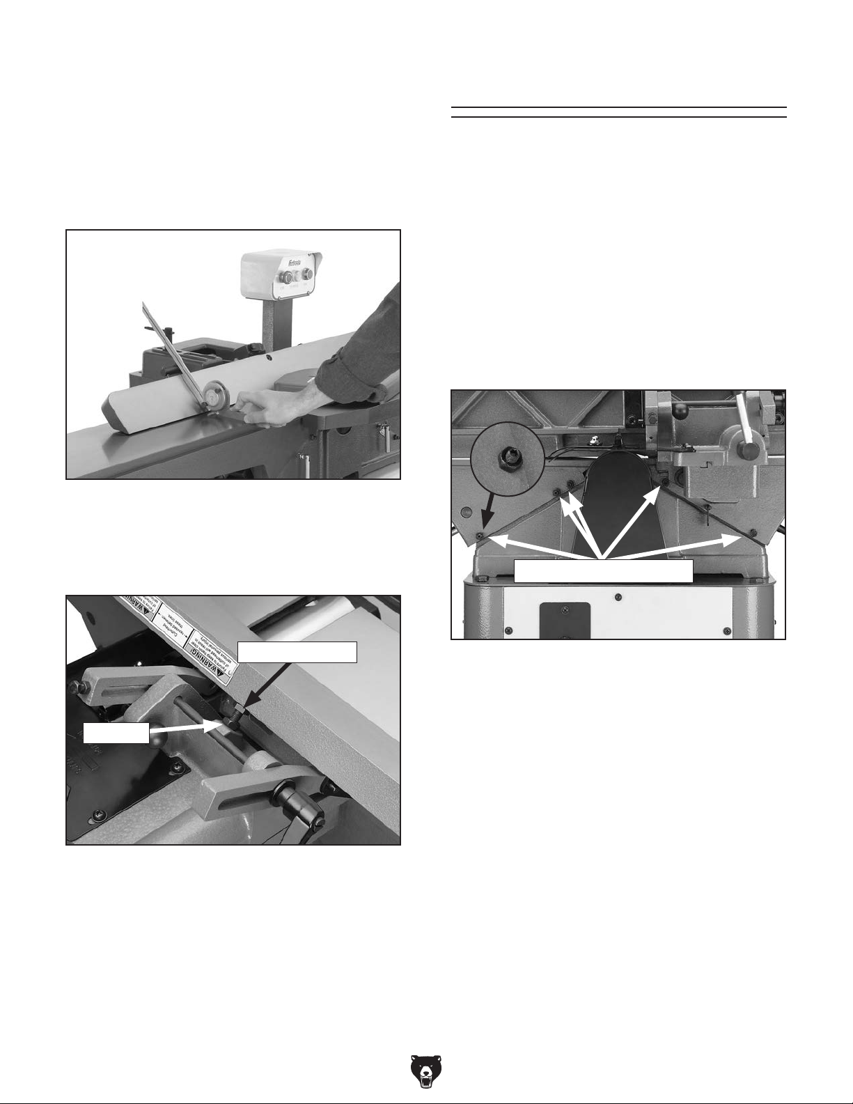
To set the 45˚ outward fence stop:
1. Pull the plunger out (see Figure 74 on Page
41).
2. Using a sliding bevel adjusted to 135˚, adjust
the fence to the 135˚ (45˚ outward) position,
as shown in Figure 75.
Adjusting Gibs
The table gibs eliminate excessive play in the
table movement, and control how easy the tables
move up and down.
Tools Needed Qty
Wrench 10mm ................................................... 1
Hex Wrench 3mm .............................................. 1
To adjust the table gibs:
1. Using a 10mm wrench, loosen the three
infeed table gib nuts on the back of the jointer
base (see Figure 77).
Figure 75. Example of adjusting fence 45˚ out-
ward.
3. Loosen the jam nut on the 45˚ outward fence
stop bolt (see Figure 76).
Fence Stop Bolt
Jam Nut
Figure 76. 45˚ outward fence stop bolt.
4. Adjust the 45˚ outward fence stop bolt until it
makes contact with the back of the fence.
5. Retighten the jam nut loosened in Step 3.
Gib Nuts and Set Screws
Figure 77. Table gib nuts and set screw loca-
tions.
2. Oil the gibs if needed (see Page 34).
3. Using a 3mm hex wrench, evenly tighten the
gib set screws a small amount, then check
the table by moving it up and down. Adjust
the set screws as needed until the friction
of the table movement is balanced between
minimal play and ease of movement.
Note: Tighter gibs reduce play but make it
harder to adjust the tables.
4. Repeat Steps 1-3 with the outfeed table, and
oil the outfeed table leadscrew, if needed.
-42-
5. Set the outfeed table height as described in
Setting Outfeed Table Height on Page 22.
Model G0654 (Mfg. Since 9/07)
Page 45

START
STOP
The motor wiring shown here is
current at the time of printing, but it
may not match your machine.
Always use the wiring diagram
inside the motor junction box.
Wiring Diagram
View this page in color at
www.grizzly.com.
Neutral
Hot
110 VAC
Ground
PUSH BUTTON SWITCH
(viewed from behind)
See Figure 78
5-15 Plug
(As Recommended)
Figure 78. Switch wiring.
Figure 79. Motor junction box and capacitor
wiring.
Model G0654 (Mfg. Since 9/07)
Ground
MOTOR
Ground
8
2
3
5
1
Start
Capacitor
200MFD
125VAC
See Figure 79
-43-
Page 46
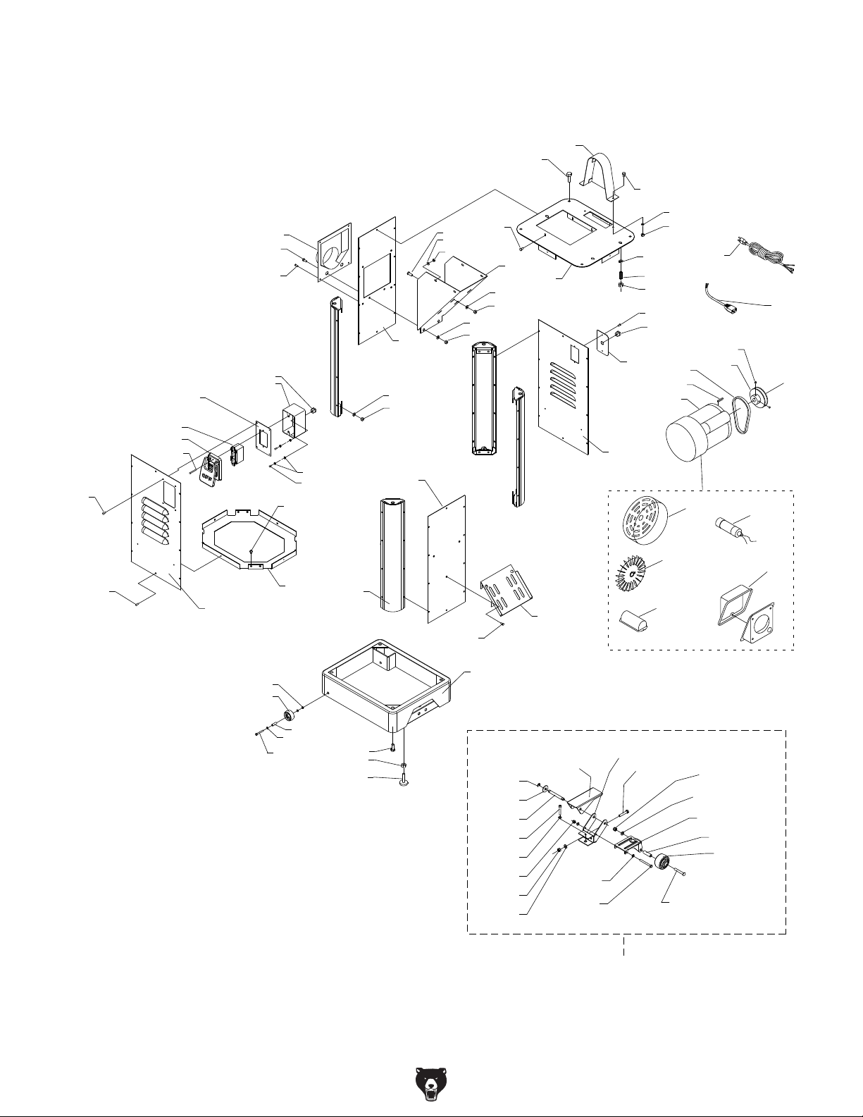
35
31
32
34
29
Stand Parts Breakdown
1
8
25
26
11
12
13
39
40
41
15
16
17
14
23
24
43
9
18
10
19
20
21
22
46
33
2
5
6
7
28
27
47
3
4
49
48
47-1
52
53
51
50
47-4
36
37
56
57
60
59
38
58
42
61
62
63
44
64
65-1
65-3
65-4
65-5
65-6
65-7
65-8
65-9
45
65-19
65-10
65-11
65-18
47-2
47-3
65-17
47-5
65-16
65-15
65-14
65-13
65-12
65-2
-44-
65
Model G0654 (Mfg. Since 9/07)
Page 47

Stand Parts List
REF PART # DESCRIPTION REF PART # DESCRIPTION
1 P0654001 BELT GUARD ASSEMBLY 45 P0654045 PUSH BLOCK HOLDER
2 PFB01M FLANGE BOLT M6-1 X 12 46 P0654046 BACK PANEL
3 PW03M FLAT WASHER 6MM 47 P0654047 MOTOR 1HP 110V
4 PN01M HEX NUT M6-1 47-1 P0654047-1 FAN COVER
5 PLW06M LOCK WASHER 10MM 47-2 P0654047-2 FAN
6 P0654006 SPECIAL STUD M10-1.5 47-3 P0654047-3 S CAPACITOR COVER
7 PN02M HEX NUT M10-1.5 47-4 PC200D S CAP 200M 125V 1-1/4 X 2-3/4
8 PB18 HEX BOLT 3/8-16 X 1 47-5 P0654047-5 JUNCTION BOX
9 PB02M HEX BOLT M6-1 X 12 48 PK12M KEY 5 X 5 X 30
10 P0654010 TOP PLATE ASSEMBLY 49 PVA36 V-BELT A-36 4L360
11 P0654011 DUST PORT 50 P0654050 MOTOR PULLEY
12 PFB01M FLANGE BOLT M6-1 X 12 51 PSS01M SET SCREW M6-1 X 10
13 PFS03 FLANGE SCREW 10-24 X 3/8 52 P0654052 POWER CORD 14AWG X 3C
14 P0654014 LEFT PANEL 53 P0654053 SWITCH CORD 16AWG X 3C
15 PCB06 CARRIAGE BOLT 5/16-18 X 1-1/4 56 PLN04M LOCK NUT M8-1.25
16 PW03M FLAT WASHER 6MM 57 P0654057 WHEEL
17 PN01M HEX NUT M6-1 58 P0654058 SLEEVE
18 P0654018 DUST CHUTE 59 PW01M FLAT WASHER 8MM
19 PW07 FLAT WASHER 5/16 60 PB86M HEX BOLT M8-1.25 X 65
20 PN02 HEX NUT 5/16-18 61 PB18 HEX BOLT 3/8-16 X 1
21 PW03M FLAT WASHER 6MM 62 PN08 HEX NUT 3/8-16
22 PN01M HEX NUT M6-1 63 P0654063 LEVELING FOOT
23 PW03M FLAT WASHER 6MM 64 P0654064 MOBILE BASE CHASSIS
24 PN01M HEX NUT M6-1 65 P0654065 PEDAL ASSEMBLY
25 P0654025 STRAIN RELIEF 6N-4 65-1 PEC10M E-CLIP 9MM
26 P0654026 SWITCH BOX 65-2 P0654065-2 SPECIAL BOLT
27 P0654027 STRAIN RELIEF 6N-4 65-3 P0654065-3 SPECIAL FLAT WASHER
28 PFS03 FLANGE SCREW 10-24 X 3/8 65-4 P0654065-4 SHAFT
29 P0654029 SWITCH BOX BRACKET 65-5 PB22M HEX BOLT M8-1.25 X 50
31 P0654031 SWITCH 65-6 PW01M FLAT WASHER 8MM
32 P0654032 SWITCH COVER 65-7 P0654065-7 SPECIAL HEX NUT M8
33 P0654033 CORD PLATE 65-8 PN02M HEX NUT M10-1.5
34 P0654034 SPECIAL SCREW M4-.7 X 20 65-9 PW04M FLAT WASHER 10MM
35 PFS03 FLANGE SCREW 10-24 X 3/8 65-10 PB45M HEX BOLT M8-1.25 X 100
36 PFS03 FLANGE SCREW 10-24 X 3/8 65-11 PW01M FLAT WASHER 8MM
37 P0654037 FRONT PANEL 65-12 P0654065-12 TROLLEY WHEEL
38 P0654038 BOTTOM PLATE 65-13 P0654065-13 SLEEVE
39 PFB01M FLANGE BOLT M6-1 X 12 65-14 P0654065-14 TROLLEY BRACKET
40 PTLW02M EXT TOOTH WASHER 5MM 65-15 PW04M FLAT WASHER 10MM
41 PS05M PHLP HD SCR M5-.8 X 8 65-16 P0654065-16 SPECIAL HEX NUT M10
42 P0654042 CABINET SUPPORT 65-17 PB144M HEX BOLT M10-1.5 X 55
43 P0654043 RIGHT PANEL 65-18 P0654065-18 PEDAL BRACKET
44 PFS03 FLANGE SCREW 10-24 X 3/8 65-19 P0654065-19 PEDAL
Model G0654 (Mfg. Since 9/07)
-45-
Page 48

Table Parts Breakdown
130
131
134
135
133
147
148
149
150
138
139
140
127
158
144
143
162
161
128
136
137
145
151
152
163
129
141
103
101
102
172
120
119
118
117
153
154
155
156
157
112
113
107
108
109
121
122
104
105
106
123
166
167
165
164
168
180
110
111
181
182
114
115
116
124
125
168
179
195
195-1
195-2
195-3
187
188
189
193
192
191
190
126
184
169
170
177
176
-46-
Model G0654 (Mfg. Since 9/07)
Page 49

Table Parts List
REF PART # DESCRIPTION REF PART # DESCRIPTION
101 P0654101 GIB 145 PSS53M SET SCREW M5-.8 X 12
102 P0654102 KNIFE 147 P0654147 INDEX PIN M6-1 X 14
103 P0654103 GIB BOLT 148 P0654148 COMPRESSION SPRING
104 P0654104 CUTTERHEAD PULLEY 149 P0654149 PLUNGER HOUSING
105 P0654105 RIGHT HAND BEARING SUPPORT 150 P0654150 BALL KNOB M6-1
106 P6203 BALL BEARING 6203ZZ 151 P0654151 POINTER
107 PK12M KEY 5 X 5 X 30 152 PS17M PHLP HD SCR M4-.7 X 6
108 PSS53M SET SCREW M5-.8 X 12 153 P0654153 PLATE
109 P0654109 SPECIAL NUT 154 P0654154 TORSION SPRING
110 PSS01M SET SCREW M6-1 X 10 155 P0654155 CUP
111 P0654111 CUTTERHEAD 156 P0654156 RETAINER
112 P6202 BALL BEARING 6202ZZ 157 PS01M PHLP HD SCR M4-.7 X 18
113 P0654113 LEFT HAND BEARING SUPPORT 158 P0654158 BLOCK ASSEMBLY
114 P0654114 SPECIAL STUD 161 P0654161 LOCK LEVER M6-1 X 30
115 PLW06M LOCK WASHER 10MM 162 PSBS23M BUTTON HD CAP SCR M8-1.25 X 25
116 PN02M HEX NUT M10-1.5 163 PW01M FLAT WASHER 8MM
117 P0654117 FENCE CARRIAGE 164 P0654164 ALIGNMENT PIN
118 PW04M FLAT WASHER 10MM 165 P0654165 BRACKET
119 PLW06M LOCK WASHER 10MM 166 PSB11M CAP SCREW M8-1.25 X 16
120 PB01M HEX BOLT M10-1.5 X 30 167 PLW04M LOCK WASHER 8MM
121 PRP39M ROLL PIN 4 X 20 168 PEC07M E-CLIP 7MM
122 P0654122 SPECIAL KEY 9.5 X 9.5 X 128 169 P0654169 LINK
123 P0654123 LOCK SCREW ASSEMBLY 170 P0654170 SPECIAL BOLT
124 PN01M HEX NUT M6-1 172 P0654172 JOINTER TABLE ASSEMBLY
125 PSS12M SET SCREW M6-1 X 25 176 PN09M HEX NUT M12-1.75
126 P0654126 GIB 177 P0654177 INFEED TABLE ADJUSTMENT LEVER
127 P0654127 PUSH BLOCK 179 PSS20M SET SCREW M8-1.25 X 8
128 PSS02M SET SCREW M6-1 X 6 180 P0654180 BLOCK
129 P0654129 SPECIAL WASHER 181 P0654181 SHAFT
130 PS14M PHLP HD SCR M6-1 X 12 182 PEC12M E-CLIP 12MM
131 PW03M FLAT WASHER 6MM 184 P0654184 SEAL
133 P0654133 HANDWHEEL 187 PWR810 WRENCH 8 X10
134 P0654134 HANDLE 188 PRW1214 WRENCH 12 X 14
135 P0654135 SHOULDER SCREW 189 PWR1417 WRENCH 14 X 17
136 P0654136 COLLAR 190 PAW02.5M HEX WRENCH 2.5MM
137 P0654137 SPECIAL WASHER 191 PAW03M HEX WRENCH 3MM
138 P0654138 BLOCK 192 PAW04M HEX WRENCH 4MM
139 PLW04M LOCK WASHER 8MM 193 PAW06M HEX WRENCH 6MM
140 PSB05M CAP SCREW M8-1.25 X 50 195 P0654195 KNIFE GAUGE ASSEMBLY
141 P0654141 SCREW SHAFT 195-1 P0654195-1 KNIFE GAUGE ROD
143 P0654143 GUARD SHAFT 195-2 P0654195-2 KNIFE GAUGE BLOCK
144 P0654144 GUARD 195-3 PEC015M E-CLIP 8MM
Model G0654 (Mfg. Since 9/07)
-47-
Page 50

Fence Parts Breakdown
205
206
238
237
225
226
215
216
217
218
213
214
223
239
209
210
211
221
208
220
207
222
227
224
212
228
229
232
233
231
230
234
235
236
-48-
219
203
204
201
Model G0654 (Mfg. Since 9/07)
Page 51

Fence Parts List
REF PART # DESCRIPTION REF PART # DESCRIPTION
201 P0654201 FENCE 221 PN03M HEX NUT M8-1.25
203 P0654203 BALL KNOB M10-1.5 222 P0654222 ALIGNMENT PIN 7 X 24
204 P0654204 STUD M10-1.5 223 P0654223 LEFT BRACKET
205 P0654203 BALL KNOB M10-1.5 224 P0654224 SPECIAL SCREW M8-1.25
206 P0654204 STUD M10-1.5 225 P0654225 SPECIAL FLAT WASHER
207 P0654207 FENCE LOCK HANDLE SHAFT 226 P0654226 LEVER ASSY M8-1.25
208 P0654208 FENCE LOCK HANDLE BOLT M12-1.75 227 P0654227 RIGHT BRACKET
209 PW06M FLAT WASHER 12MM 228 PS14M PHLP HD SCR M6-1 X 12
210 P0654210 SPECIAL NUT M12 229 PW03M FLAT WASHER 6MM
211 P0654211 FENCE SLIDE BRACKET 230 P0654230 REAR GUARD BASE
212 PSS04M SET SCREW M6-1 X 12 231 P0654231 REAR GUARD TOP
213 PN03M HEX NUT M8-1.25 232 PN35M ACORN NUT M6-1
214 PB26M HEX BOLT M8-1.25 X 30 233 PW03M FLAT WASHER 6MM
215 P0654215 BRACKET 234 P0654234 EXTENSION SPRING
216 PSB155M CAP SCREW M8-1.25 X 14 235 PB10M HEX BOLT M6-1 X 25
217 PW01M FLAT WASHER 8MM 236 PN01M HEX NUT M6-1
218 P0654218 SUPPORT BRACKET 237 P0654237 SHAFT LOCK M6-1
219 P0654219 ALIGNMENT PIN 7 X 24 238 P0654238 BALL KNOB M6-1
220 PB26M HEX BOLT M8-1.25 X 30 239 PSS26M SET SCREW M5-.8 X 6
Model G0654 (Mfg. Since 9/07)
-49-
Page 52

Label Placement
310
311
309
308
307
306
300
301
302
303
304
305
REF PART # DESCRIPTION REF PART # DESCRIPTION
300 P0654300 FENCE/CUTTERHEAD LABEL 306 P0654306 EAR PROTECTION/RESPIRATOR
301 PLABEL-29 CUTTERHEAD GUARD LABEL 307 P0654307 UNPLUG 110V POWER
302 PLABEL-14 ELECTRICITY LABEL 308 P0654308 MACHINE ID LABEL
303 PLABEL-12A READ MANUAL -VERTICAL NS 7/05 309 PPAINT-11 PUTTY TOUCH-UP PAINT
304 PLABEL-11 SAFETY GLASSES 2" X 3-5/16" 310 P-PAINT1 GRIZZLY GREEN TOUCH-UP PAINT
305 G8588 SMALL GRIZZLY NAMEPLATE 311 P0654311 RED TOUCH-UP PAINT
Safety labels warn about machine hazards and ways to prevent injury. The owner of this machine
MUST maintain the original location and readability of the labels on the machine. If any label is
removed or becomes unreadable, REPLACE that label before using the machine again. Contact
Grizzly at (800) 523-4777 or www.grizzly.com to order new labels.
-50-
Model G0654 (Mfg. Since 9/07)
Page 53

WARRANTY CARD
Name _____________________________________________________________________________
Street _____________________________________________________________________________
City _______________________ State _________________________ Zip _____________________
Phone # ____________________ Email _________________________________________________
Model # ____________________ Order # _______________________ Serial # __________________
The following information is given on a voluntary basis. It will be used for marketing purposes to help us develop
better products and services. Of course, all information is strictly confidential.
1. How did you learn about us?
____ Advertisement ____Friend ____ Catalog
____ Card Deck ____ Website ____ Other:
2. Which of the following magazines do you subscribe to?
____ Cabinetmaker & FDM
____ Family Handyman
____ Hand Loader
____ Handy
____ Home Shop Machinist
____ Journal of Light Cont.
____ Live Steam
____ Model Airplane News
____ Old House Journal
____ Popular Mechanics
3. What is your annual household income?
____ $20,000-$29,000 ____ $30,000-$39,000 ____ $40,000-$49,000
____ $50,000-$59,000 ____ $60,000-$69,000 ____ $70,000+
CUT ALONG DOTTED LINE
4. What is your age group?
____ 20-29 ____ 30-39 ____ 40-49
____ 50-59 ____ 60-69 ____ 70+
5. How long have you been a woodworker/metalworker?
____ 0-2 Years ____ 2-8 Years ____ 8-20 Years ____20+ Years
6. How many of your machines or tools are Grizzly?
____ 0-2 ____ 3-5 ____ 6-9 ____10+
____ Popular Science
____ Popular Woodworking
____ Precision Shooter
____ Projects in Metal
____ RC Modeler
____ Rie
____ Shop Notes
____ Shotgun News
____ Today’s Homeowner
____ Wood
____ Wooden Boat
____ Woodshop News
____ Woodsmith
____ Woodwork
____ Woodworker West
____ Woodworker’s Journal
____ Other:
7. Do you think your machine represents a good value? _____Yes _____No
8. Would you recommend Grizzly Industrial to a friend? _____Yes _____No
9. Would you allow us to use your name as a reference for Grizzly customers in your area?
Note: We never use names more than 3 times. _____Yes _____No
10. Comments: _____________________________________________________________________
_________________________________________________________________________________
_________________________________________________________________________________
_________________________________________________________________________________
Page 54

FOLD ALONG DOTTED LINE
FOLD ALONG DOTTED LINE
Place
Stamp
Here
GRIZZLY INDUSTRIAL, INC.
P.O. BOX 2069
BELLINGHAM, WA 98227-2069
Send a Grizzly Catalog to a friend:
Name_______________________________
Street_______________________________
City______________State______Zip______
TAPE ALONG EDGES--PLEASE DO NOT STAPLE
Page 55

WARRANTY AND RETURNS
We shall in no event be liable for death, injuries to persons or property or for incidental, contingent, special,
WARRANTY AND RETURNS
Grizzly Industrial, Inc. warrants every product it sells for a period of 1 year to the original purchaser from
the date of purchase. This warranty does not apply to defects due directly or indirectly to misuse, abuse,
negligence, accidents, repairs or alterations or lack of maintenance. This is Grizzly’s sole written warranty
and any and all warranties that may be implied by law, including any merchantability or fitness, for any particular purpose, are hereby limited to the duration of this written warranty. We do not warrant or represent
that the merchandise complies with the provisions of any law or acts unless the manufacturer so warrants.
In no event shall Grizzly’s liability under this warranty exceed the purchase price paid for the product and
any legal actions brought against Grizzly shall be tried in the State of Washington, County of Whatcom.
or consequential damages arising from the use of our products.
To take advantage of this warranty, contact us by mail or phone and give us all the details. We will then
issue you a “Return Number,’’ which must be clearly posted on the outside as well as the inside of the
carton. We will not accept any item back without this number. Proof of purchase must accompany the
merchandise.
The manufacturers reserve the right to change specifications at any time because they constantly strive to
achieve better quality equipment. We make every effort to ensure that our products meet high quality and
durability standards and we hope you never need to use this warranty.
Please feel free to write or call us if you have any questions about the machine or the manual.
Thank you again for your business and continued support. We hope to serve you again soon.
Page 56

 Loading...