

Page 1

MODEL G0640X
17" METAL/WOOD BANDSAW
OWNER'S MANUAL
(For models manufactured since 12/17)
COPYRIGHT © JANUARY, 2008 BY GRIZZLY INDUSTRIAL, INC., REVISED AUGUST, 2018 (KB)
WARNING: NO PORTION OF THIS MANUAL MAY BE REPRODUCED IN ANY SHAPE
OR FORM WITHOUT THE WRITTEN APPROVAL OF GRIZZLY INDUSTRIAL, INC.
#TR9556 PRINTED IN TA I WAN
V3.08.18
Page 2

This manual provides critical safety instructions on the proper setup,
operation, maintenance, and service of this machine/tool. Save this
document, refer to it often, and use it to instruct other operators.
Failure to read, understand and follow the instructions in this manual
may result in fire or serious personal injury—including amputation,
electrocution, or death.
The owner of this machine/tool is solely responsible for its safe use.
This responsibility includes but is not limited to proper installation in
a safe environment, personnel training and usage authorization,
proper inspection and maintenance, manual availability and comprehension, application of safety devices, cutting/sanding/grinding tool
integrity, and the usage of personal protective equipment.
The manufacturer will not be held liable for injury or property damage
from negligence, improper training, machine modifications or misuse.
Some dust created by power sanding, sawing, grinding, drilling, and
other construction activities contains chemicals known to the State
of California to cause cancer, birth defects or other reproductive
harm. Some examples of these chemicals are:
• Lead from lead-based paints.
• Crystalline silica from bricks, cement and other masonry products.
• Arsenic and chromium from chemically-treated lumber.
Your risk from these exposures varies, depending on how often you
do this type of work. To reduce your exposure to these chemicals:
Work in a well ventilated area, and work with approved safety equipment, such as those dust masks that are specially designed to filter
out microscopic particles.
Page 3

Table of Contents
INTRODUCTION ............................................... 2
Contact Info.................................................... 2
Manual Accuracy ........................................... 2
Identification ................................................... 3
Machine Data Sheet ...................................... 4
SECTION 1: SAFETY ....................................... 6
Safety Instructions for Machinery .................. 6
Additional Safety for Metal-Wood Bandsaws 8
SECTION 2: POWER SUPPLY ........................ 9
SECTION 3: SETUP ....................................... 11
Needed for Setup ......................................... 11
Unpacking .................................................... 11
Inventory ...................................................... 12
Hardware Recognition Chart ....................... 13
Cleanup ........................................................ 14
Site Considerations ...................................... 14
Lifting & Placing ........................................... 15
Anchoring to Floor ....................................... 15
Assembly ..................................................... 16
Blade Tracking ............................................. 19
Test Run ...................................................... 20
Blade Tensioning ......................................... 21
Adjusting Blade Guides ............................... 22
Adjusting Support Bearings ......................... 23
Adjusting Positive Stop ................................ 24
Aligning Table .............................................. 25
Aligning Fence ............................................. 26
Miter Gauge ................................................. 26
SECTION 4: OPERATIONS ........................... 27
Guide Post ................................................... 27
Quick-Release Blade Tension ..................... 28
Table Tilt ...................................................... 28
Blade Terminology ....................................... 29
Blade Selection ............................................ 29
Blade Breakage ........................................... 31
Blade Care & Break-In ................................. 31
Blade Changes ............................................ 32
Blade Speed ................................................ 33
SECTION 5: WOOD CUTTING ...................... 34
Workpiece Inspection................................... 34
Cutting Tips .................................................. 34
Ripping ......................................................... 35
Crosscutting ................................................. 35
Resawing ..................................................... 36
Stacked Cuts................................................ 37
Cutting Curves ............................................. 37
Cutting Circles.............................................. 37
SECTION 6: METAL CUTTING ...................... 38
Workpiece Inspection................................... 38
Cutting Tips .................................................. 38
Choosing Blades and Speeds ..................... 39
Metal Chip Inspection Chart ........................ 40
SECTION 7: ACCESSORIES ......................... 41
SECTION 8: MAINTENANCE ......................... 43
Schedule ...................................................... 43
Cleaning ....................................................... 43
Wheel Brush ................................................ 43
Lubrication ................................................... 43
Redressing Rubber Tires ............................. 45
SECTION 9: SERVICE ................................... 46
Troubleshooting ........................................... 46
Replacing V-Belts ........................................ 48
Adjusting Wheel Brush ................................ 48
Wheel Alignment .......................................... 49
Shimming Table ........................................... 51
Blade Lead ................................................... 51
Adjusting Tension Lever .............................. 52
SECTION 10: WIRING .................................... 53
Wiring Safety Instructions ............................ 53
Wiring Diagram ............................................ 54
Electrical Component Wiring ....................... 55
SECTION 11: PARTS ..................................... 56
Main ............................................................. 56
Fence & Blade Guides ................................. 59
Labels & Cosmetics ..................................... 62
WARRANTY & RETURNS ............................. 65
Page 4
INTRODUCTION
We stand behind our machines! If you have questions or need help, contact us with the information
below. Before contacting, make sure you get the
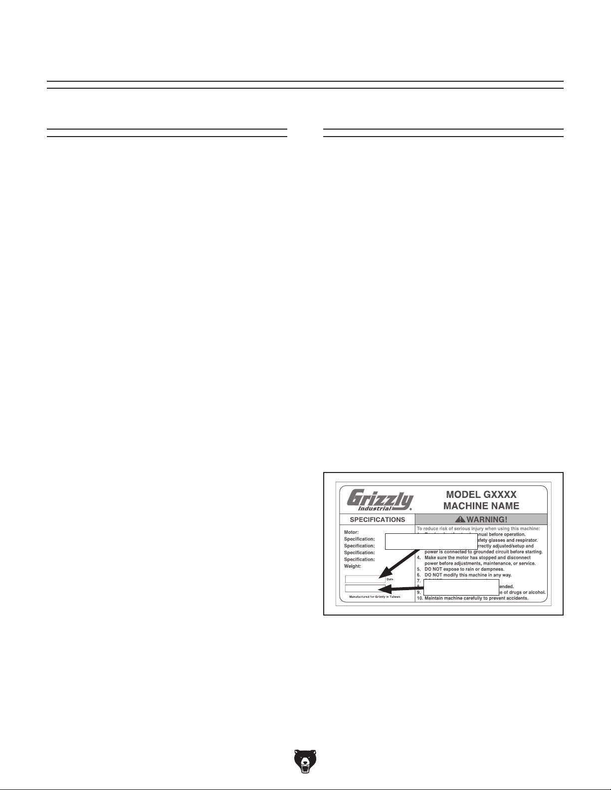
serial number
from the
machine ID label. This will help us help you faster.
We want your feedback on this manual. What did
you like about it? Where could it be improved?
Please take a few minutes to give us feedback.
Email: manuals@grizzly.com
We are proud to provide a high-quality owner’s
manual with your new machine!
We
instructions, specifications, drawings, and photographs
in this manual. Sometimes we make mistakes, but
our policy of continuous improvement also means
that
you receive is
slightly different than shown in the manual
If you find this to be the case, and the difference
between the manual and machine leaves you
confused or unsure about something
check our
website for an updated version. W
current
manuals and
on our web-
site at
Alternatively, you can call our Technical Support
for help. Before calling, make sure you write down
the
from
the machine ID label (see below). This information
is required for us to provide proper tech support,
and it helps us determine if updated documentation is available for your machine.
Contact Info
and manufacture date
Grizzly Technical Support
1815 W. Battlefield
Springfield, MO 65807
Phone: (570) 546-9663
Email: techsupport@grizzly.com
Grizzly Documentation Manager
P.O. Box 2069
Bellingham, WA 98227-2069
Manual Accuracy
made every effort to be exact with the
sometimes the machine
.
,
e post
manual updates for free
www.grizzly.com.
Manufacture Date and Serial Number
Manufacture Date
Serial Number
-2-
Model G0640X (Mfd. Since 12 /17)
Page 5
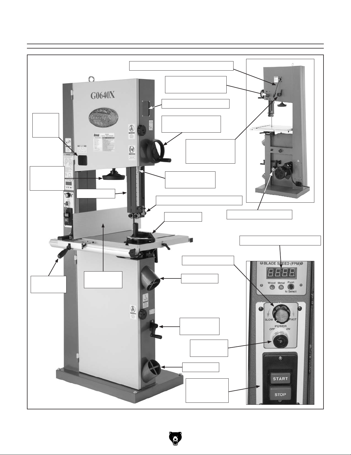
Identification
Quick-Release Blade Tension Lever
Blade Guide
Elevation Lock Knob
Blade Tension Window
Blade
Tension
Window
Blade
Tension
Handwheel
Fence Lock
Handle
Blade Guard
Rip Fence
Attachment
Blade Guide Height
Handwheel
Blade Tracking
Knob with Lock
Lever
Blade Guide
Height Indicator
Upper Blade Guide Assembly
Miter Gauge
Blade Speed Dial
4" Dust Port
Belt Engagement Disc
Digital Blade Speed Display
Model G0640X (Mfd. Since 12 /17)
Belt Tension
Crank
Main Power
Key Switch
4" Dust Port
Motor
START/STOP
Switch
-3-
Page 6

Machine Data Sheet
MACHINE DATA
SHEET
Customer Service #: (570) 546-9663 · To Order Call: (800) 523-4777 · Fax #: (800) 438-5901
MODEL G0640X 17" METAL/WOOD BANDSAW W/INVERTER
MOTOR
Product Dimensions:
Weight.............................................................................................................................................................. 378 lbs.
Width (side-to-side) x Depth (front-to-back) x Height........................................................................... 32 x 32 x 73 in.
Footprint (Length x Width)..................................................................................................................... 27 x 17-3/4 in.
Shipping Dimensions:
Type................................................................................................................................................... Wood Slat Crate
Content........................................................................................................................................................... Machine
Weight.............................................................................................................................................................. 416 lbs.
Length x Width x Height....................................................................................................................... 20 x 31 x 81 in.
Must Ship Upright.................................................................................................................................................... No
Electrical:
Power Requirement........................................................................................................... 220V, Single-Phase, 60 Hz
Prewired Voltage.................................................................................................................................................. 220V
Full-Load Current Rating.......................................................................................................................................... 8A
Minimum Circuit Size.............................................................................................................................................. 15A
Connection Type....................................................................................................................................... Cord & Plug
Power Cord Included.............................................................................................................................................. Yes
Power Cord Length................................................................................................................................................. 6 ft.
Power Cord Gauge......................................................................................................................................... 14 AWG
Plug Included........................................................................................................................................................... No
Recommended Plug Type..................................................................................................................................... 6-15
Switch Type............................................................................................ ON/OFF Push Button Switch w/Lockout Key
Inverter (VFD) Type................................................................................................................................. Delta VFD-M
Inverter (VFD) Size............................................................................................................................................... 2 HP
Motors:
Main
Main Specifications:
Main Specifications
-4-
Horsepower................................................................................................................................................ 2 HP
Phase.................................................................................................................................................... 3-Phase
Amps.............................................................................................................................................................. 8A
Speed................................................................................................................................................ 1725 RPM
Type........................................................................................................................................... TEFC Induction
Power Transfer .................................................................................................................................. Belt Drive
Bearings..................................................................................................... Shielded & Permanently Lubricated
Bandsaw Size............................................................................................................................................ 17 in.
Max Cutting Width (Left of Blade)........................................................................................................ 16-1/4 in.
Max Cutting Width (Left of Blade) w/Fence......................................................................................... 13-3/4 in.
Max Cutting Height.................................................................................................................................... 12 in.
Blade Speeds............................................................................................................ Variable 100 – 3600 FPM
Model G0640X (Mfd. Since 12 /17)
Page 7

Blade Information
Standard Blade Length...................................................................................................................... 131-1/2 in.
Blade Width Range............................................................................................................................. 1/8 – 1 in.
Blade Guides................................................................................................................................... Ball Bearing
Table Information
Table Length........................................................................................................................................ 23-5/8 in.
Table Width......................................................................................................................................... 17-1/4 in.
Table Thickness.................................................................................................................................... 1-1/2 in.
Table Tilt - Left/Right.......................................................................................................... Left 5, Right 45 deg.
Floor-to-Table Height........................................................................................................................... 37-1/2 in.
Includes Fence............................................................................................................................................. Yes
Construction Materials
Table....................................................................................................................... Precision-Ground Cast Iron
Fence.................................................................................................................................. Extruded Aluminum
Base/Stand............................................................................................................................. Pre-Formed Steel
Body/Frame............................................................................................................................ Pre-Formed Steel
Wheels........................................................................................................................ Fully-Balanced Cast Iron
Tires........................................................................................................................................................ Rubber
Wheel Covers......................................................................................................................... Pre-Formed Steel
Paint Type/Finish....................................................................................................................... Powder Coated
Other Related Information
Wheel Diameter......................................................................................................................................... 17 in.
Wheel Width.......................................................................................................................................... 1-3/8 in.
Tire Width............................................................................................................................................ 1-1/16 in.
Number of Dust Ports....................................................................................................................................... 2
Dust Port Size.............................................................................................................................................. 4 in.
Compatible Mobile Base........................................................................................................................ D2057A
Other Specifications:
Country of Origin .............................................................................................................................................. Taiwan
Warranty ........................................................................................................................................................... 1 Year
Approximate Assembly & Setup Time .............................................................................................................. 1 Hour
Serial Number Location ............................................................................ ID Label on Center of Upper Wheel Cover
Sound Rating ..................................................................................................................................................... 78 dB
ISO 9001 Factory .................................................................................................................................................. Yes
Certified by a Nationally Recognized Testing Laboratory (NRTL) .......................................................................... No
Like all machinery there is potential danger
when operating this machine. Accidents
are frequently caused by lack of familiarity
or failure to pay attention. Use this machine
with respect and caution to decrease the
risk of operator injury. If normal safety precautions are overlooked or ignored, serious personal injury may occur.
No list of safety guidelines can be complete. Every shop environment is different.
Always consider safety first, as it applies
to your individual working conditions. Use
this and other machinery with caution and
respect. Failure to do so could result in
serious personal injury, damage to equipment, or poor work results.
Model G0640X (Mfd. Since 12 /17)
-5-
Page 8

SECTION 1: SAFETY
For Your Own Safety, Read Instruction
Manual Before Operating This Machine
The purpose of safety symbols is to attract your attention to possible hazardous conditions.
This manual uses a series of symbols and signal words intended to convey the level of importance of the safety messages. The progression of symbols is described below. Remember that
safety messages by themselves do not eliminate danger and are not a substitute for proper
accident prevention measures. Always use common sense and good judgment.
Indicates an imminently hazardous situation which, if not avoided,
WILL result in death or serious injury.
Indicates a potentially hazardous situation which, if not avoided,
COULD result in death or serious injury.
Indicates a potentially hazardous situation which, if not avoided,
MAY result in minor or moderate injury. It may also be used to alert
against unsafe practices.
This symbol is used to alert the user to useful information about
NOTICE
proper operation of the machine.
Safety Instructions for Machinery
OWNER’S MANUAL. Read and understand this
owner’s manual BEFORE using machine.
TRAINED OPERATORS ONLY. Untrained operators have a higher risk of being hurt or killed.
Only allow trained/supervised people to use this
machine. When machine is not being used, disconnect power, remove switch keys, or lock-out
machine to prevent unauthorized use—especially
around children. Make your workshop kid proof!
DANGEROUS ENVIRONMENTS. Do not use
machinery in areas that are wet, cluttered, or have
poor lighting. Operating machinery in these areas
greatly increases the risk of accidents and injury.
MENTAL ALERTNESS REQUIRED. Full mental
alertness is required for safe operation of machinery. Never operate under the influence of drugs or
alcohol, when tired, or when distracted.
ELECTRICAL EQUIPMENT INJURY RISKS. You
can be shocked, burned, or killed by touching live
electrical components or improperly grounded
machinery. To reduce this risk, only allow qualified
service personnel to do electrical installation or
repair work, and always disconnect power before
accessing or exposing electrical equipment.
DISCONNECT POWER FIRST.
nect machine from power supply BEFORE making
adjustments, changing tooling, or servicing machine.
This prevents an injury risk from unintended startup
or contact with live electrical components.
EYE PROTECTION. Always wear ANSI-approved
safety glasses or a face shield when operating or
observing machinery to reduce the risk of eye
injury or blindness from flying particles. Everyday
eyeglasses are NOT approved safety glasses.
Always discon-
-6-
Model G0640X (Mfd. Since 12 /17)
Page 9

WEARING PROPER APPAREL. Do not wear
clothing, apparel or jewelry that can become
entangled in moving parts. Always tie back or
cover long hair. Wear non-slip footwear to reduce
risk of slipping and losing control or accidentally
contacting cutting tool or moving parts.
HAZARDOUS DUST. Dust created by machinery
operations may cause cancer, birth defects, or
long-term respiratory damage. Be aware of dust
hazards associated with each workpiece material. Always wear a NIOSH-approved respirator to
reduce your risk.
HEARING PROTECTION. Always wear hearing protection when operating or observing loud
machinery. Extended exposure to this noise
without hearing protection can cause permanent
hearing loss.
REMOVE ADJUSTING TOOLS. Tools left on
machinery can become dangerous projectiles
upon startup. Never leave chuck keys, wrenches,
or any other tools on machine. Always verify
removal before starting!
USE CORRECT TOOL FOR THE JOB. Only use
this tool for its intended purpose—do not force
it or an attachment to do a job for which it was
not designed. Never make unapproved modifications—modifying tool or using it differently than
intended may result in malfunction or mechanical
failure that can lead to personal injury or death!
AWKWARD POSITIONS. Keep proper footing
and balance at all times when operating machine.
Do not overreach! Avoid awkward hand positions
that make workpiece control difficult or increase
the risk of accidental injury.
CHILDREN & BYSTANDERS. Keep children and
bystanders at a safe distance from the work area.
Stop using machine if they become a distraction.
GUARDS & COVERS. Guards and covers reduce
accidental contact with moving parts or flying
debris. Make sure they are properly installed,
undamaged, and working correctly BEFORE
operating machine.
FORCING MACHINERY. Do not force machine.
It will do the job safer and better at the rate for
which it was designed.
NEVER STAND ON MACHINE. Serious injury
may occur if machine is tipped or if the cutting
tool is unintentionally contacted.
STABLE MACHINE. Unexpected movement during operation greatly increases risk of injury or
loss of control. Before starting, verify machine is
stable and mobile base (if used) is locked.
USE RECOMMENDED ACCESSORIES. Consult
this owner’s manual or the manufacturer for recommended accessories. Using improper accessories will increase the risk of serious injury.
UNATTENDED OPERATION. To reduce the
risk of accidental injury, turn machine OFF and
ensure all moving parts completely stop before
walking away. Never leave machine running
while unattended.
MAINTAIN WITH CARE. Follow all maintenance
instructions and lubrication schedules to keep
machine in good working condition. A machine
that is improperly maintained could malfunction,
leading to serious personal injury or death.
DAMAGED PARTS. Regularly inspect machine
for damaged, loose, or mis-adjusted parts—or
any condition that could affect safe operation.
Immediately repair/replace BEFORE operating
machine. For your own safety, DO NOT operate
machine with damaged parts!
MAINTAIN POWER CORDS. When disconnecting cord-connected machines from power, grab
and pull the plug—NOT the cord. Pulling the cord
may damage the wires inside. Do not handle
cord/plug with wet hands. Avoid cord damage by
keeping it away from heated surfaces, high traffic
areas, harsh chemicals, and wet/damp locations.
EXPERIENCING DIFFICULTIES. If at any time
you experience difficulties performing the intended operation, stop using the machine! Contact our
Technical Support at (570) 546-9663.
Model G0640X (Mfd. Since 12 /17)
-7-
Page 10

Additional Safety for Metal/Wood Bandsaws
Serious cuts, amputation, or death can occur from contact with the moving saw blade during
operation, if blade breaks, or if fingers, hair, or clothing get entangled. Long-term respiratory
damage can occur from breathing metal/wood dust created while cutting. To reduce this risk,
anyone operating this machine MUST completely heed the hazards and warnings below.
HAND PLACEMENT. Placing hands or fingers
in line with blade during operation may result in
serious injury if hands slip or workpiece moves
unexpectedly. Do not position fingers or hands in
line with blade, and never reach under table while
blade is moving.
WORKPIECE MATERIAL. This machine is
intended for cutting natural woods, man-made
wood products, laminate-covered wood, steel,
aluminum, copper, cast iron, and plastics. DO
NOT cut magnesium—using the wrong cutting
fluid could lead to chip fire and possible explosion. This machine is NOT designed to cut glass,
stone, tile, chains, cables, round or oblongshaped workpieces, and workpieces with internal
or built-in moving or rotating parts, etc.
CUTTING TECHNIQUES. To avoid blade getting
pulled off wheels or accidentally breaking and
striking operator, always turn bandsaw OFF and
wait for blade to come to a complete stop before
backing workpiece out of blade. DO NOT back
workpiece away from blade while bandsaw is running. DO NOT force or twist blade while cutting,
especially when sawing small curves. This could
result in blade damage or breakage.
CLEARING JAMS AND CUTOFFS. Always allow
blade to stop on its own. DO N O T try to stop or slow
blade with your hand or the workpiece. Always
stop bandsaw and disconnect power before clearing scrap pieces that get stuck between blade and
table insert. Use brush or push stick, not hands, to
clean chips/cutoff scraps from table.
BLADE SPEED/FEED RATE. Cutting workpiece
before blade is at full speed could cause blade to
grab workpiece and pull hands into blade. Allow
blade to reach full speed before starting cut. DO
NOT start machine with workpiece contacting
blade. To avoid risk of operator injury, always feed
stock evenly and smoothly.
BLADE CONDITION. Dull blades require more
effort to perform cut, increasing risk of accidents.
Do not operate with dirt y, dull, cracked or badly
worn blades. Inspect blades for cracks and missing teeth before each use. Always maintain proper
blade tension and tracking while operating.
CHIP COLLECTION. DO NOT collect metal dust
cuttings in a wood dust collector. Use a dedicated
metal dust collector or shop vacuum to collect
metal cuttings. DO NOT mix wood dust and metal
cuttings, as it may cause a fire.
CUTTING FLUID SAFETY. Cutting fluids are
poisonous. Always follow manufacturer’s cuttingfluid safety instructions. Pay particular attention
to contact, contamination, inhalation, storage and
disposal warnings. Spilled cutting fluid invites slipping hazards.
SMALL/NARROW WORKPIECES. If hands slip
during a cut while holding small workpieces
with fingers, serious personal injury could occur.
Always support/feed small or narrow workpieces
with push sticks, push blocks, jig, vise, or some
type of clamping fixture.
UPPER BLADE GUIDE SUPPORT. To reduce
exposure of operator to blade and provide maximum blade support while cutting, keep upper
blade guides adjusted to just clear workpiece.
WORKPIECE SUPPORT. To maintain maximum
control and reduce risk of blade contact/breakage,
always ensure adequate support of long, large, or
unstable workpieces. Always keep workpiece flat
and firm against table/fence when cutting to avoid
loss of control. If necessary, use a jig or vise.
BLADE REPLACEMENT. To avoid mishaps that
could result in operator injury, make sure blade
teeth face down toward table and blade is properly tensioned and tracked before operating.
-8-
Model G0640X (Mfd. Since 12 /17)
Page 11
SECTION 2: POWER SUPPLY
Before installing the machine, consider the availability and proximity of the required power supply
circuit. If an existing circuit does not meet the
requirements for this machine, a new circuit must
be installed. To minimize the risk of electrocution,
fire, or equipment damage, installation work and
electrical wiring must be done by an electrician or
qualified service personnel in accordance with all
applicable codes and standards.
or equipment damage
may occur if machine is
not properly grounded
and connected to power
The full-load current rating is the amperage a
machine draws at 100% of the rated output power.
On machines with multiple motors, this is the
amperage drawn by the largest motor or sum of all
motors and electrical devices that might operate
at one time during normal operations.
The full-load current is not the maximum amount
of amps that the machine will draw. If the machine
is overloaded, it will draw additional amps beyond
the full-load rating.
If the machine is overloaded for a sufficient length
of time, damage, overheating, or fire may result—
especially if connected to an undersized circuit.
To reduce the risk of these hazards, avoid overloading the machine during operation and make
sure it is connected to a power supply circuit that
meets the specified circuit requirements.
For your own safety and protection of
Note: Circuit requirements in this manual apply to
a dedicated circuit—where only one machine will
be running on the circuit at a time. If machine will
be connected to a shared circuit where multiple
machines may be running at the same time, consult an electrician or qualified service personnel to
ensure circuit is properly sized for safe operation.
A power supply circuit includes all electrical
equipment between the breaker box or fuse panel
in the building and the machine. The power supply circuit used for this machine must be sized to
safely handle the full-load current drawn from the
machine for an extended period of time. (If this
machine is connected to a circuit protected by
fuses, use a time delay fuse marked D.)
This machine is prewired to operate on a power
supply circuit that has a verified ground and meets
the following requirements:
Availability
Electrocution, fire, shock,
supply.
Full-Load Current Rating
Circuit Information
property, consult an electrician if you are
unsure about wiring practices or electrical
codes in your area.
Full-Load Current Rating at 220V ....... 8 Amps
Model G0640X (Mfd. Since 12 /17)
Circuit Requirements
Nominal Voltage .........208V, 22 0V, 2 30V, 240V
Cycle .......................................................... 60 Hz
Phase ........................................... Single-Phase
Power Supply Circuit ......................... 15 Amps
Plug/Receptacle ............................. NEMA 6-15
-9-
Page 12
Improper connection of the equipment-grounding
wire can result in a risk of electric shock. The
wire with green insulation (with or without yellow
stripes) is the equipment-grounding wire. If repair
or replacement of the power cord or plug is necessary, do not connect the equipment-grounding
wire to a live (current carrying) terminal.
Check with a qualified electrician or service personnel if you do not understand these grounding
requirements, or if you are in doubt about whether
the tool is properly grounded. If you ever notice
that a cord or plug is damaged or worn, disconnect it from power, and immediately replace it with
a new one.
We do not recommend using an extension cord
with this machine.
cord, only use it if absolutely necessary and only
on a temporary basis.
Extension cords cause voltage drop, which can
damage electrical components and shorten motor
life. Voltage drop increases as the extension cord
size gets longer and the gauge size gets smaller
(higher gauge numbers indicate smaller sizes).
Any extension cord used with this machine must
be in good condition and contain a ground wire
and matching plug/receptacle. Additionally, it must
meet the following size requirements:
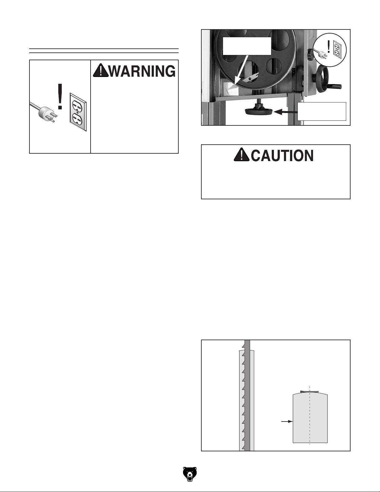
Grounding Requirements
This machine MUST be grounded. In the event
of certain malfunctions or breakdowns, grounding
reduces the risk of electric shock by providing a
path of least resistance for electric current.
This machine is equipped with a power cord that
has an equipment-grounding wire and a grounding
plug. Only insert plug into a matching receptacle
(outlet) that is properly installed and grounded in
accordance with all local codes and ordinances.
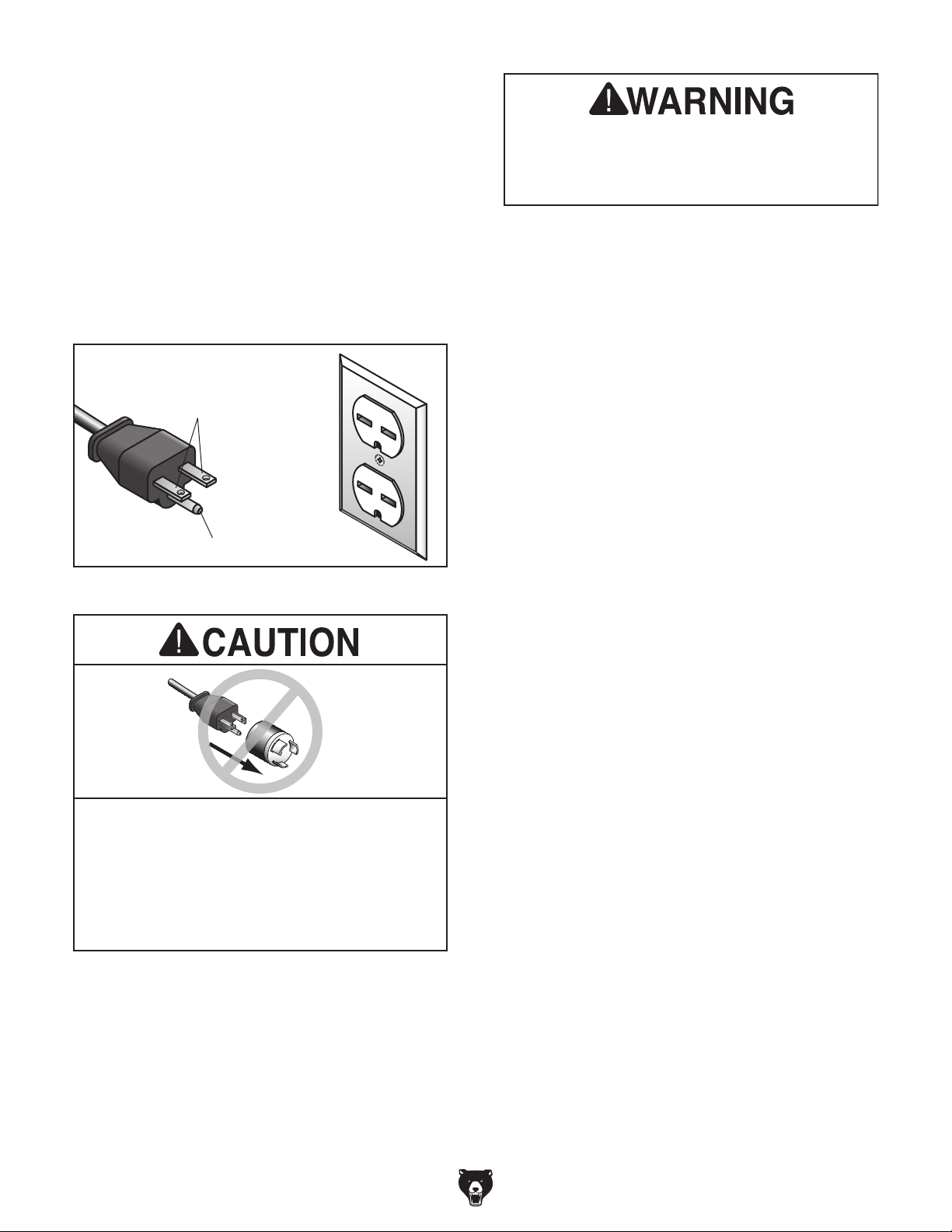
DO NOT modify the provided plug!
No adapter should be used with plug. If
process. DO NOT connect to power until
GROUNDED
6-15 RECEPTACLE
Current Carrying Prongs
6-15 PLUG
Serious injury could occur if you connect
machine to power before completing setup
instructed later in this manual.
Grounding Prong
Figure 1. Typical 6-15 plug and receptacle.
plug does not fit available receptacle, or if
machine must be reconnected for use on a
different type of circuit, reconnection must
be performed by an electrician or qualified
service personnel, and it must comply with
all local codes and ordinances.
-10 -
Extension Cords
If you must use an extension
Minimum Gauge Size ...........................14 AWG
Maximum Length (Shorter is Better).......50 ft.
Model G0640X (Mfd. Since 12 /17)
Page 13
SECTION 3: SETUP
get help from other people
This machine was carefully packaged for safe
transport. When unpacking, separate all enclosed
items from packaging materials and inspect them
for shipping damage.
,
please
IMPORTANT:
you are completely satisfied with the machine and
have resolved any issues between Grizzly or the
shipping agent. You MUST have the original pack-
aging to file a freight claim. It is also extremely
helpful if you need to return your machine later.
Keep children and pets away
from plastic bags or packing
materials shipped with this
Needed for Setup
This machine presents
serious injury hazards
to untrained users. Read
through this entire manual to become familiar with
the controls and operations before starting the
machine!
Wear safety glasses during
the entire setup process!
HEAVY LIFT!
Straining or crushing injury
may occur from improperly
lifting machine or some of
its parts. To reduce this risk,
The following items are needed to complete the
setup process, but are not included with your
machine:
Description Qty
• Straightedge ............................................... 1
• Level ........................................................... 1
• Another Person for Lifting Help .................. 1
• Forklift ......................................................... 1
• Lifting Strap or Chain (500-lb. min. cap.) ... 1
• Lifting Hook or Shackle .............................. 1
• Square ........................................................ 1
• Feeler Gauge 0.016" .................................. 1
• Safety Glasses (for each person) ............... 1
• Wet/Dry Vacuum for Dust Collection.......... 1
• Vacuum Adaptor 4" ..................................... 1
• Dust Hose Y-Fitting 4" ................................ 1
• Dust Hose 4" (length as needed) ............... 2
• Hose Clamp 4" ........................................... 4
and use a forklift (or other
lifting equipment) rated for
weight of this machine.
Model G0640X (Mfd. Since 12 /17)
Unpacking
If items are damaged
call us immediately at (570) 546-9663.
Save all packaging materials until
SUFFOCATION HAZARD!
machine. Discard immediately.
-11-
Page 14
Inventory
The following is a list of items shipped with your
machine. Before beginning setup, lay these items
out and inventory them.
If any non-proprietary parts are missing (e.g. a
nut or a washer), we will gladly replace them; or
for the sake of expediency, replacements can be
obtained at your local hardware store.
Keep children and pets away
from plastic bags or packing
materials shipped with this
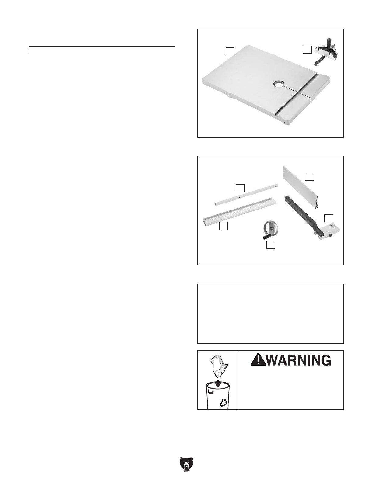
Main Components (Figures 2–3) Qty
A. Bandsaw (not shown) ................................. 1
B. Table ........................................................... 1
C. Miter Gauge ................................................ 1
D. Fence Assembly ......................................... 1
E. Resaw Fence Attachment .......................... 1
F. Front Fence Rail ......................................... 1
G. Rear Fence Rail ......................................... 1
H. Guide Post Handwheel............................... 1
Fasteners Qty
Hex Bolt M8-1.25 x 90 (Positive Stop) ............... 1
Hex Nut M8-1.25 (Positive Stop) ....................... 1
Hex Bolts M8-1.25 x 25 (Table) ......................... 4
Lock Washers 8mm (Table) .............................. 4
Flat Washers 8mm (Table) ................................ 4
Cap Screws M6-1 x 16 (Rear Rail) .................... 2
Hex Bolts M6-1 x 20 (Front Rail) ....................... 2
Lock Washers 6mm (Front Rail) ........................ 2
Flat Washers 6mm (Front Rail) ......................... 2
Hex Nut M8-1.25 (Fence Lock Lever) ................ 1
Flat Washer 8mm (Attachment Lock Handle) ... 1
Tools & Other Miscellaneous Items Qty
Hex Wrench 5mm .............................................. 1
Hex Wrench 8mm .............................................. 1
Open End Wrench 10/13mm ............................. 1
Table Pin ............................................................ 1
Table Insert ........................................................ 1
Fence Lock Lever M8-1.25 x 22 ........................ 1
Fence Attachment Lock Handle M8-1.25 x 44 . . 1
Fence Attachment T-Slot Nut ............................ 1
B
Figure 2. Table components.
G
F
H
Figure 3. Fence components.
C
E
D
D
NOTICE
If you cannot find an item on this list, carefully check around/inside the machine and
packaging materials. Often, these items get
lost in packaging materials while unpacking or they are pre-installed at the factory.
SUFFOCATION HAZARD!
-12-
machine. Discard immediately.
Model G0640X (Mfd. Since 12 /17)
Page 15
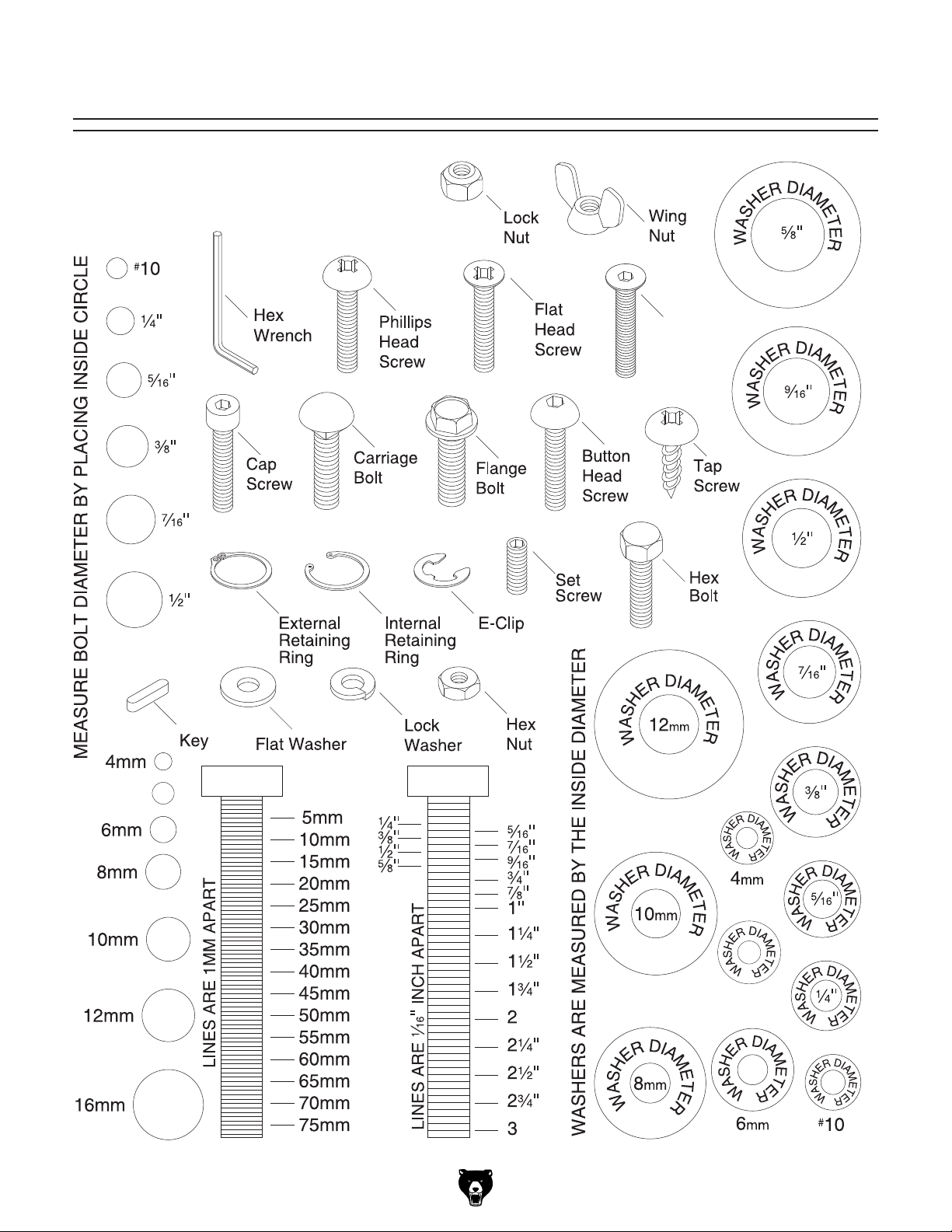
Hardware Recognition Chart
USE THIS CHART TO MATCH UP
HARDWARE DURING THE INVENTORY
AND ASSEMBLY PROCESS.
Flat
Head
Cap
Screw
5mm
Model G0640X (Mfd. Since 12 /17)
5mm
-13-
Page 16
Cleanup
The unpainted surfaces of your machine are
coated with a heavy-duty rust preventative that
prevents corrosion during shipment and storage.
This rust preventative works extremely well, but it
will take a little time to clean.
Be patient and do a thorough job cleaning your
machine. The time you spend doing this now will
give you a better appreciation for the proper care
of your machine's unpainted surfaces.
There are many ways to remove this rust preventative, but the following steps work well in a wide
variety of situations. Always follow the manufacturer’s instructions with any cleaning product you
use and make sure you work in a well-ventilated
area to minimize exposure to toxic fumes.
Before cleaning, gather the following:
• Disposable rags
• Cleaner/degreaser (WD•40 works well)
• Safety glasses & disposable gloves
• Plastic paint scraper (optional)
Basic steps for removing rust preventative:
1.
2.
amount of cleaner/degreaser, then let it soak
3.
scrape off as much as you can first, then wipe
4.
then coat all unpainted surfaces with a quality
or disable start switch or
Site Considerations
Floor Load
Refer to the Machine Data Sheet for the weight
and footprint specifications of your machine.
Some residential floors may require additional
reinforcement to support both the machine and
operator.
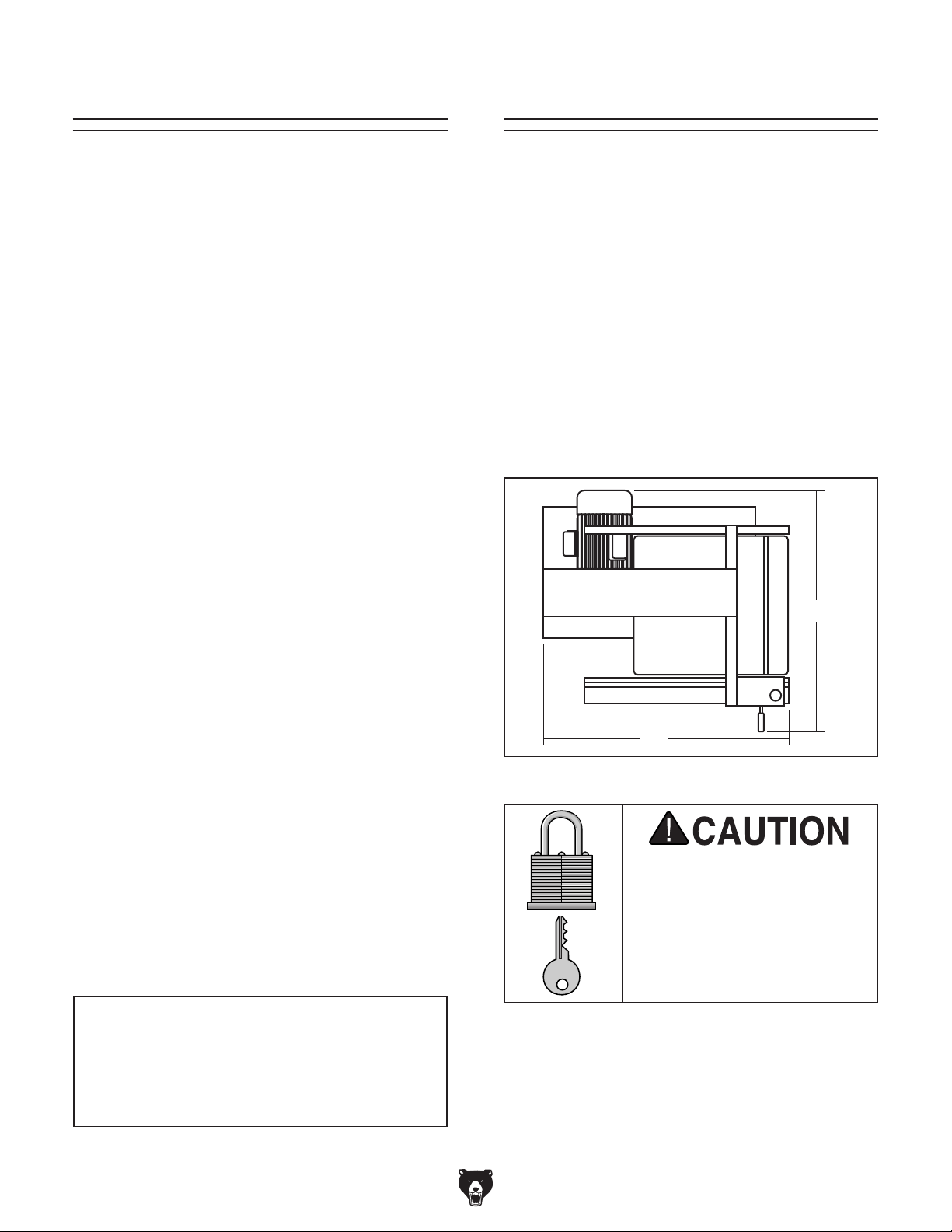
Placement Location
Consider existing and anticipated needs, size of
material to be processed through each machine,
and space for auxiliary stands, work tables or
other machinery when establishing a location for
your new machine. See Figure 4 for the minimum
working clearances.
Put on safety glasses.
Coat the rust preventative with a liberal
for 5–10 minutes.
Wipe off the surfaces. If your cleaner/degreas-
er is effective, the rust preventative will wipe
off easily. If you have a plastic paint scraper,
off the rest with the rag.
Repeat Steps 2–3 as necessary until clean,
metal protectant to prevent rust.
NOTICE
Avoid harsh solvents like acetone or brake
parts cleaner that may damage painted surfaces. Always test on a small, inconspicuous location first.
32"
36"
Figure 4. Minimum working clearances.
Children and visitors may be
seriously injured if unsupervised around this machine.
Lock entrances to the shop
power connection to prevent
unsupervised use.
-14-
Model G0640X (Mfd. Since 12 /17)
Page 17

get help from other people
Anchoring machinery to the floor prevents tipping
or shifting and reduces vibration that may occur
during operation, resulting in a machine that runs
slightly quieter and feels more solid.
If the machine will be installed in a commercial or
workplace setting, or if it is permanently connected (hardwired) to the power supply, local codes
may require that it be anchored to the floor.
If not required by any local codes, fastening the
machine to the floor is an optional step. If you
choose not to do this with your machine, we recommend placing it on machine mounts, as these
provide an easy method for leveling and they have
vibration-absorbing pads.
Lag shield anchors with lag screws (see below)
are a popular way to anchor machinery to a concrete floor, because the anchors sit flush with the
floor surface, making it easy to unbolt and move
the machine later, if needed. However, anytime
local codes apply, you MUST follow the anchoring
methodology specified by the code.
Lifting & Placing
Anchoring to Floor
HEAVY LIFT!
Straining or crushing injury
may occur from improperly
lifting machine or some of
its parts. To reduce this risk,
and use a forklift (or other
lifting equipment) rated for
weight of this machine.
Special care should be taken when moving this
bandsaw. Only use the following methods to lift or
move this bandsaw.
To move and place machine:
1. Use a forklift to move the bandsaw on the
pallet near its final location.
2. Unbolt the bandsaw from the pallet.
Number of Mounting Holes ............................ 4
Diameter of Mounting Hardware ................
7
⁄16"
Anchoring to Concrete Floors
3. Place the lifting hook through the eye bolt
(see Figure 5) that is located on top of the
machine.
4. Carefully lift the machine and place where
desired.
Figure 5. Lifting the bandsaw.
Eye Bolt
Lag Screw
Flat Washer
Machine Base
Concrete
Figure 6. Popular method for anchoring
machinery to a concrete floor.
Lag Shield Anchor
Drilled Hole
Model G0640X (Mfd. Since 12 /17)
-15-
Page 18
Assembly
The machine must be fully assembled before it
can be operated. Before beginning the assembly
process, refer to
and gather
all
To ensure the assembly process
goes smoothly, first clean any
covered or coated in heavy-duty rust preventative (if
applicable).
listed items.
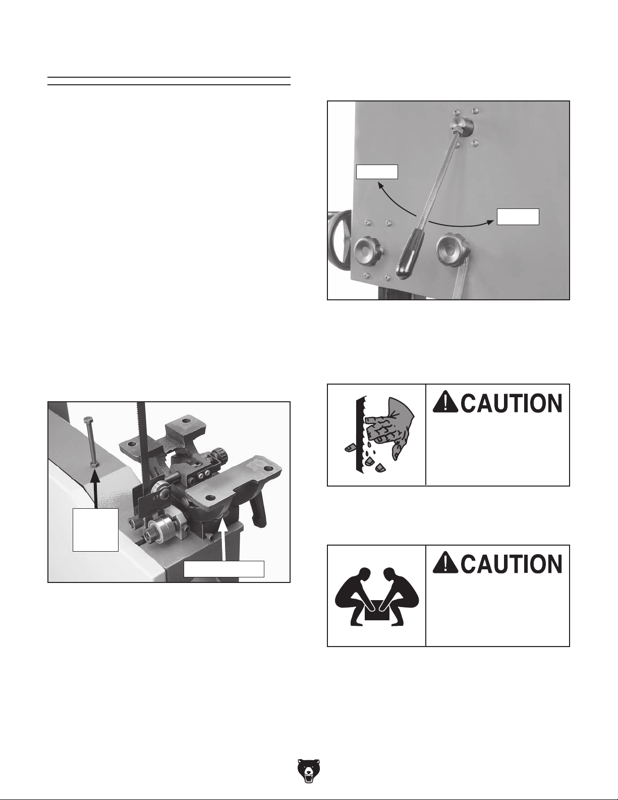
4. Loosen blade tension by rotating the quick-
release tension lever clockwise as shown in
Figure 8.
Needed for Setup
parts that are
Loosen
To assemble the bandsaw:
1. Thread (1) M8-1.25 hex nut half way up the
length of the included M8-1.25 x 90 hex bolt
(the longest one in the hardware bag).
2. Thread the M8-1.25 x 90 hex bolt (otherwise
known as the "Positive Stop Bolt") into the
casting near the trunnion base, as shown in
Figure 7.
Note: The positive stop bolt acts as a table
stop, which makes it easy to bring the table
back to 90° after tilting it.
Tighten
Figure 8. Quick-release tension lever.
5. Adjust the upper and lower blade guides
away from the blade. Refer to Adjusting
Blade Guides on Page 22 for more details.
The saw blade is very
sharp and can easily cut
bare hands. Wear heavy
leather gloves whenever
handling blade.
Positive
Stop
Bolt
Table Trunnion
Figure 7. Positive stop bolt installed.
3. Slide guide post handwheel onto shaft and
thread attached M6-1 x 20 cap screw through
side of handwheel and against shaft to
secure handwheel in place.
-16 -
6. Open the upper and lower wheel covers, and
slide the blade off of both wheels.
The table is heavy. To
reduce the risk of injury
when lifting, have another
person help you during
the next step.
7. Place the table onto the trunnion and posi-
tion it so the mounting holes in the table are
aligned with those on the trunnion.
Model G0640X (Mfd. Since 12 /17)
Page 19

8. Attach the table to the trunnion with (4)
M8-1.25 x 25 hex bolts, (4) 8mm lock washers,
and (4) 8mm flat washers.
9. With the blade teeth pointing downward, slide
the blade through the table slot.
10. Slide the blade through the upper and lower
blade guides, and mount it over the upper
and lower wheels.
15. Install (1) M8-1.25 hex nut on the fence lock
lever, then thread the handle into the fence
assembly (see Figure 10). Tighten the hex
nut against the fence pivot block to secure
the handle.
11. Tighten the quick-release tension lever, then
install the table insert and table pin.
Note: Keep the upper and lower blade guides
adjusted away from the blade until the blade
tracking and tension have been adjusted
during later steps.
12. Adjust the blade tension until the mark on the
blade tension scale is between 4 and 6.
13. Attach the rear rail to the table with (2) M6-1
x 16 cap screws (see Figure 9).
14. Attach the front rail with (2) M6-1 x 20 hex
bolts, (2) 6mm lock washers, and (2) 6mm flat
washers, as shown in Figure 9.
M8-1.25
Hex Nut
Figure 10. Handle installed on fence assembly.
16. Place (1) 8mm flat washer on the fence
attachment lock handle, slide it through the
hole in the fence, then thread the T-slot nut
onto the end of the lock handle threads.
17. Slide the resaw fence over the T-slot nut,
as shown in Figure 11, so the T-slot nut fits
inside the channel of the resaw fence, then
tighten the lock handle.
Pivot Block
Fence Lock Lever
Rear View
Figure 9. Rail installation.
Model G0640X (Mfd. Since 12 /17)
Front View
Resaw Fence
Lock Handle
T-Slot
Nut
Figure 11. Attaching resaw fence to fence.
-17-
Page 20
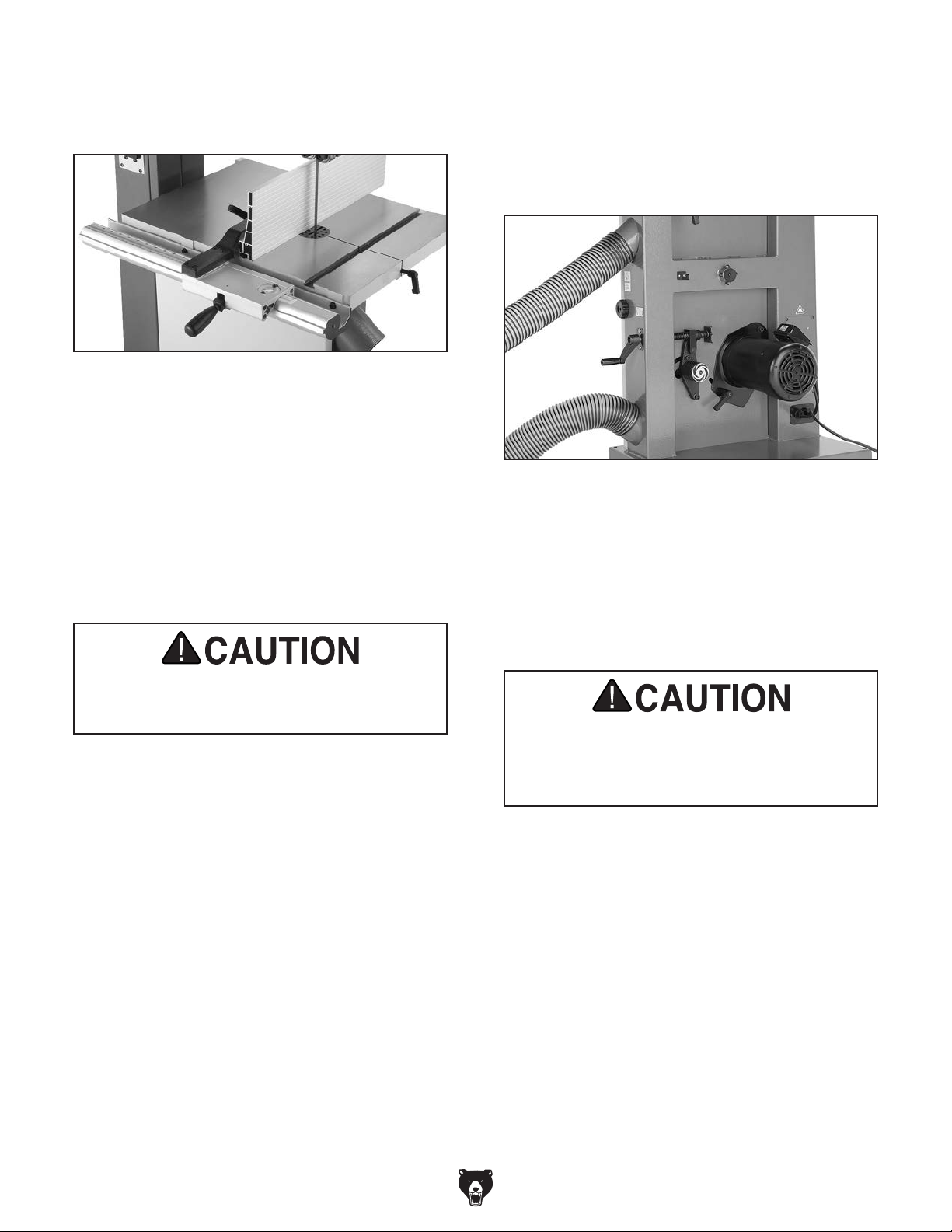
18. Pull the fence lock lever up and place the
fence assembly on the front rail, as shown in
Figure 12.
Figure 12. Correctly installed fence.
19. Adjust the rail pad against the rear rail until
there is an even gap between the bottom of
the fence and the table, then tighten the rail
pad hex nut against the fence to secure the
rail pad in place.
22. Fit a 4" dust hose or 4" adapter over each
dust port and secure in place with hose
clamps, as shown in Figure 13.
Note: A tight fit is necessary for proper
performance.
Figure 13. Dust hoses attached to dust ports.
20. Slide the fence against the blade.
21. Place a straightedge across the table and line
it up over the fence scale indicator line.
This saw creates substantial amounts of fine
dust while operating. Failure to use a vacuum
system can result in respiratory illness.
23. If cutting both wood and metal, connect this
machine to a shop vacuum rather than a
dust collector. Most dust collectors are not
designed to capture metal shavings and
doing so may lead to a fire from wood dust
contacting hot metal cuttings or sparks from
metal pieces hitting a dust collector impeller.
Mixing wood dust and metal cuttings may
cause a fire. Do not collect metal shavings in
a regular wood dust collector. Instead use a
shop vacuum to collect metal cuttings.
-18-
Model G0640X (Mfd. Since 12 /17)
Page 21
Blade Tracking
Blade Centered
on Peak of Crown
Blade
Centered
on
Wheel
Wheel
Serious personal injury
can occur if the machine
starts while your hand
is touching the bandsaw
wheel during tracking
adjustments. Disconnect
power from the bandsaw
before performing blade
tracking adjustments.
Blade Tension
Scale
Blade Tension
Handwheel
Figure 14. Blade tensioning controls.
"Blade Tracking" refers to how the blade rides on
the wheels. When tracking correctly, the blade
rides in the center of the rim part of the wheels.
Blade tracking is primarily controlled by adjusting the upper wheel tilt. Tracking the blade in
this manner is referred to as "Center Tracking,"
because you tilt the wheel until the blade rides in
the center.
Another way to track the blade is known as
"Coplanar Tracking." Coplanar tracking involves
aligning the wheels so they are parallel and
aligned (see Wheel Alignment on Page 49).
When wheels are coplanar, vibration and heat are
reduced during operation.
The wheels on the Model G0640X are factory
aligned, so center tracking is the only adjustment
that needs to be performed during setup.
To center track the blade:
Cast-iron spokes may have sharp edges
and blade teeth may extend beyond edge of
wheel, creating a laceration hazard. Be careful when turning wheel by hand.
4. Spin the upper wheel by hand at least three
times and watch how the blade rides on the
crown of the wheel. Refer to Figure 15 for an
illustration of this concept.
—If the blade rides in the center of the
upper wheel and is centered on the peak
of the wheel crown, then the bandsaw is
already tracked properly and no further
adjustments are needed at this time.
—If the blade does not ride in the center
of the upper wheel and is not centered
on the peak of the wheel crown, then
continue with the following steps.
1. DISCONNECT MACHINE FROM POWER!
2. Make sure the upper and lower blade guides
are adjusted away from the blade.
3. Engage the quick tension lever and turn the
blade tension handwheel until the tension
scale (Figure 14) reads between 4 and 6.
Model G0640X (Mfd. Since 12 /17)
Figure 15. Center tracking profiles.
-19 -
Page 22

5. Loosen the lock lever shown in Figure 16 so
Once assembly is complete, test run the machine
to ensure it is properly connected to power and
safety components are functioning correctly.
If you find an unusual problem during the test run,
immediately stop the machine, disconnect it from
power, and fix the problem BEFORE operating the
machine again. The
table in the
SERVICE section of this manual can help.
that the blade tracking knob can rotate.
To test run the machine:
1. Make sure you have read the safety instruc-
tions at the beginning of the manual and that
you have followed all previous setup instructions in this section.
Blade Tracking
Knob
Lock Lever
Figure 16. Blade tracking controls.
6. Spin the upper wheel with one hand and
slowly rotate the tracking control knob with
the other hand to make the blade ride in the
center of the bandsaw wheel tire.
7. Close the upper wheel cover.
8. Fine tune the blade tracking (as instructed
in the following Test Run procedure) while
the bandsaw is running, then tighten the lock
lever attached to the blade tracking knob.
2. Make sure all tools and objects used during
setup are cleared away from the machine
and that the wheel covers are closed and
latched.
3. Connect the machine to the power source.
4. Lower the upper blade guide assembly to
approximately 1" over the table.
5. Turn the variable speed dial counterclockwise (toward the SLOW side) all the way.
6. Turn the power key switch to the ON position.
7. Press START, allow the bandsaw to run for
two seconds, then press STOP. This will give
the blade enough time to start tracking off the
wheel if the tracking is set incorrectly.
8. Look through the blade tracking window (see
Figure 17) and notice the position of the
blade on the wheel.
NOTICE
Changes in the blade tension may change
the blade tracking.
Test Run
-20-
Troubleshooting
Figure 17. Blade tracking window.
Model G0640X (Mfd. Since 12 /17)
Page 23

—If the blade is positioned in the center of
the wheel, continue to the next step.
Blade Tensioning
— If the blade is positioned near the edge of
one side of the wheel, then the tracking
needs to be adjusted before continuing.
Disconnect the saw from power and repeat
the Blade Tracking instructions on Page
19.
9. Turn the bandsaw ON and watch the blade
through the blade tracking window. SLOWLY
adjust the tracking knob until the blade rides
in the center of the wheel, then tighten the
lock lever attached to the blade tracking
knob.
10. Turn the variable speed to the FAST direction
to make sure the blade speed increases, then
return the variable speed dial all the way to
the SLOW position.
11. Turn the machine OFF by pressing the STOP
button.
Note: The power key switch is provided to
restrict unauthorized users from operating
the bandsaw. It is not intended as a way for
stopping the bandsaw during regular operation.
A properly tensioned blade is essential for making
accurate cuts and is required before making many
bandsaw adjustments. (Every time you replace
the blade, perform this procedure because all
blades tension differently.) The numbers on the
tension scale are arbitrary, but help you keep
track of different tensions for different blades.
To tension the bandsaw blade:
1. Complete the Test Run procedure and make
sure the blade is tracking properly.
2. Raise the upper blade guide assembly as
high as it will go, and adjust the upper and
lower blade guides at least a
the blade.
Note: This procedure will NOT work if the
blade guides are close to the blade.
3. Engage the quick tension lever to the tightened position and turn the blade tension
handwheel until the tension scale is at 5.
4. Turn the bandsaw ON.
1
⁄4" away from
12. Turn the power key switch to the OFF posi-
tion.
13. Test the power key switch by pressing the
START button. The bandsaw should not
operate while the power key switch is in the
OFF position.
Note: Although the power key switch pre-
vents the machine from starting, it will not
completely cut all power to the machine. Do
not rely on the power key switch to disconnect the bandsaw from power for service,
adjustments, or maintenance. Instead, you
must physically unplug the power cord to disconnect the machine from power.
If the previous tests were successful, the Test
Run procedure is complete.
5. Slowly release the tension one quarter of a
turn at a time. When you see the bandsaw
blade start to flutter, stop decreasing the tension.
6. Now, slowly increase the tension until the
blade stops fluttering, then tighten the tension
another quarter turn.
7. Look at what the tension gauge reads and
use that as a guide for tensioning that blade
in the future.
Note: Always untension the blade after use
to increase bearings and blade lifespan.
8. Re-adjust the blade tracking as instructed on
Page 19.
NOTICE
To reduce blade stretching, remove tension
from the blade when not in use.
Model G0640X (Mfd. Since 12 /17)
-21-
Page 24

Adjusting Blade
Guides
The blade guides provide side-to-side support to
help keep the blade straight while cutting. The
blade guides are designed to be adjusted in two
ways—forward/backward and side-to-side.
Approximately
0.016"
Blade
Gullets
To adjust the upper and lower blade guides:
1. Make sure the blade is tracking properly and
that it is correctly tensioned.
2. DISCONNECT BANDSAW FROM POWER!
3. Familiarize yourself with the upper blade
guide controls shown in Figure 18.
Blade
Guide
Bearings
Bearing Rotation
Knurled
Knob
Figure 18. Blade guide controls.
4. Loosen the cap screw on the lateral adjust-
ment rod and adjust the blade guides until
the edges of the bearings are
blade gullets, as illustrated in Figure 19.
1
Note: The
larger blades it may not be possible. In such
cases, adjust the guide bearings as far forward as possible to the blade gullets, and still
maintain the proper support bearing spacing
adjustment.
/16" spacing is ideal, although with
Adjustment Cap
Lateral
Adjustment
Rod Cap
Screw
Screw
1
/16" behind the
Blade
Guide
Bearing
Figure 19. Lateral adjustment of blade guides.
NOTICE
Make sure that the blade teeth will not contact the guide bearings when the blade is
against the rear support bearing during the
cut or the blade teeth will be ruined.
5. Tighten the cap screw on the lateral adjust-
ment rod.
6. Loosen the bearing rotation adjustment cap
screws.
7. Use the knurled knob to rotate the bearings
0.004" away from the blade.
Note: 0.004" is approximately the thickness
of a dollar bill.
8. Tighten the cap screw to lock the blade guide
bearings in position.
9. Repeat this procedure for the lower guides.
(All though the lower guides are set up a little
differently, the concept is the same.)
NOTICE
Whenever changing a blade or adjusting tension and tracking, the upper and lower blade
support bearings and guide bearings must
be properly adjusted before cutting operations.
-22-
Model G0640X (Mfd. Since 12 /17)
Page 25

Adjusting Support
Bearings
4. Check that the blade is approximately 90° to
the face of the support bearing as illustrated
in Figure 21 (it is not critical that it be precisely 90°—just make sure it is close.)
NOTICE
Whenever changing a blade or adjusting tension and tracking, the upper and lower blade
support bearings and blade guide bearings
must be properly adjusted before cutting
operations.
The support bearings are positioned behind
the blade for support during cutting operations.
Proper adjustment of the support bearings is an
important part of making accurate cuts and also
keeps the blade teeth from coming in contact with
the guide bearings while cutting.
To adjust the support bearings:
1. Make sure the blade is tracking properly and
that it is correctly tensioned.
2. DISCONNECT BANDSAW FROM POWER!
3. Familiarize yourself with the upper support
bearing controls shown in Figure 20.
Guide Block
Support
Bearing Cap
Screw
Assembly
Cap Screw
Bandsaw
Blade
Support
Bearing
Figure 21. Blade should be perpendicular (90°)
to the face of the support bearing.
—If the support bearing is 90° to the blade,
no adjustment to the guide block rotation is
necessary.
—If the support bearing is not 90° to the
blade, loosen the two guide block assembly cap screws, rotate the blade guide
assembly side-to-side, until the blade is
90° the face of the support bearing as illustrated in Figure 21, then tighten the guide
block assembly cap screws and re-adjust
the blade guides.
5. Loosen the support bearing cap screw.
6. Place a 0.016" feeler gauge between the
support bearing and the blade, and position
the bearing 0.016" away from the back of the
blade, as illustrated in Figure 22.
Guide Block
Adjustment Shaft
Cap Screw
Figure 20. Upper support bearing controls.
Model G0640X (Mfd. Since 12 /17)
0.016''
Figure 22. Blade should be aligned approxi-
mately 0.016" away from the bearing edge.
-23-
Page 26

Note: For a quick gauge, fold a dollar bill in half
twice (four thicknesses of a dollar bill is approximately 0.016") and place it between the support
bearing and the blade as shown in Figure 23.
Figure 23. Dollar bill folded twice to make an
approximate 0.016" gauge.
7. Tighten the support bearing cap screw.
To adjust the lower support bearings:
1. Make sure the blade is tracking properly and
that it is correctly tensioned.
2. DISCONNECT BANDSAW FROM POWER!
4. Check to make sure the support bearing is
positioned directly behind the blade.
—If the support bearing is positioned directly
behind the blade, continue on to the next
step.
—If the support bearing is not positioned
directly behind the blade, loosen the trunnion mounting cap screws and shift the
trunnion assembly over until the support
bearing is behind the blade.
Note: The table must be re-aligned with the
blade if the trunnion assembly is moved.
Refer to Page 25.
5. Loosen the cap screw on the support bearing
adjustment shaft.
6. Place a 0.016" feeler gauge between the
support bearing and the blade, and use
the adjustment knob to position the bearing
0.016" away from the back of the blade (similar to Figure 22) or use a dollar bill (Figure
23) instead of a feeler gauge.
7. Tighten the cap screw to keep the support
bearing locked in place.
3. Familiarize yourself with the lower support
bearing controls shown in Figure 24.
Adjustment
Knob
Support
Bearing
Support
Bearing
Trunnion Mounting
Cap Screw (1 of 2)
Figure 24. Lower support bearing controls.
Adjustment
Shaft Cap
Screw
Adjusting Positive
Stop
An adjustable positive stop allows the table to
easily return to 90° after tilting. After adjusting the
positive stop to 90°, the pointer on the table tilt
scale should be adjusted to the 0° mark to ensure
that the table tilt scale is accurate.
To set the positive stop 90° to the blade:
1. Make sure the blade is correctly tensioned as
described in the Blade Tensioning instructions on Page 21.
2. DISCONNECT MACHINE FROM POWER!
-24-
Model G0640X (Mfd. Since 12 /17)
Page 27

3. Loosen the lock handle that secures the table
trunnions.
Aligning Table
4. Loosen the hex nut that locks the positive
stop bolt in place.
5. Raise the upper blade guide assembly and
place a 6" machinist’s square or try-square
on the table next to the side of the blade, as
illustrated in Figure 25. Adjust the positive
stop bolt to raise or lower the table until the
table is 90° to the blade.
To ensure cutting accuracy when the table is first
installed, the table should be aligned so that the
miter slot is parallel to the bandsaw blade. This
procedure works best with a
To align the table so the miter slot is parallel
to the bandsaw blade:
1. Make sure that the blade is tracking properly
and that it is correctly tensioned.
2. DISCONNECT MACHINE FROM POWER!
3. Loosen the table mounting bolts that secure
the trunnions to the table.
4. Place a straightedge on the table, so it
lightly touches both the front and back of the
blade.
Note: Make sure the straightedge fits between
the teeth so the tooth set does not skew it.
3
⁄4" blade installed.
Figure 25. Squaring table to blade.
6. Tighten the lock handle, and lock the positive
stop bolt by tightening the hex nut against the
casting. Ensure that the bolt does not turn by
holding it with another wrench while tightening the hex nut.
7. Loosen the pointer screw at the table tilt
scale.
8. Align the tip of the pointer with the 0° mark on
the table tilt scale.
9. Tighten the pointer screw.
5. Use a fine ruler to gauge the distance
between the straightedge and the miter slot.
The distance you measure should be the
same at both the front and the back of the
table (see Figure 26).
Figure 26. Measuring for miter slot to be parallel
with blade.
Model G0640X (Mfd. Since 12 /17)
6. Adjust the table as needed for proper align-
ment.
7. Tighten the table mounting bolts.
-25-
Page 28

Aligning Fence Miter Gauge
The fence must be parallel to the miter slot in
order to yield accurate results.
To check/align the fence parallel with the
miter slot:
1. Mount the fence next to the miter slot and
examine the edges of each.
— If the fence is parallel with the miter slot,
then no adjustments are necessary.
— If the fence is NOT parallel with the miter
slot, continue to Step 2.
2. Loosen the four cap screws located on the
top face of the fence (Figure 27).
The miter gauge needs to be calibrated to the
blade when it is first mounted in the miter slot.
To calibrate the miter gauge:
1. Place a machinist's square on the table so
one edge is evenly touching the blade face,
as shown in Figure 28, and the other edge is
touching the miter gauge.
Figure 27. Four fence cap screws.
3. Adjust the fence face parallel with the edge of
the miter slot.
4. Tighten the four cap screws, being careful not
to move the fence.
NOTICE
Adjusting the fence parallel to the miter slot
does not guarantee straight cuts. The miter
slot may need to be adjusted parallel to the
side of the blade, which is covered in the
Aligning Table instructions on Page 25.
Figure 28. Squaring miter gauge to blade.
2. Loosen the lock knob on the miter gauge
and adjust it until flush with the edge of the
square.
3. Tighten the lock knob, and verify the setting.
Note: Sometimes the tightening procedure
can affect the adjustment.
4. Adjust the stop screw and related lock nut on
the underside of the miter gauge. This stop
screw allows the miter gauge to return to the
exact measurement repeatedly without using
the square.
5. Loosen the screw that secures the angle
pointer and adjust the pointer to the 0° mark
on the scale.
6. Retighten the screw that secures the angle
pointer.
-26-
7. Repeat Steps 1–4 with the two 45° stops,
using a 45° square as a gauge.
Model G0640X (Mfd. Since 12 /17)
Page 29

SECTION 4: OPERATIONS
To reduce your risk of
serious injury, read this
entire manual BEFORE
ing loss can occur while operating this
Children or untrained people can be
. This
To help prevent unsupervised operation,
switch before leaving
using machine.
Eye injuries, respiratory problems, or hear-
tool. Wear personal protective equipment to
reduce your risk from these hazards.
Guide Post
The guide post, shown in Figure 29, connects
the upper blade guide assembly to the bandsaw.
The guidepost allows the blade guide assembly to
move up or down via a rack and pinion. In order to
cut accurately, the blade guide assembly must be
no more than
all times—this positioning provides the best support for the blade.
1
⁄4" from the top of the workpiece at
Guide Post
Lock Knob
If you are not experienced with this type
of machine, WE STRONGLY RECOMMEND
that you seek additional training outside of
this manual. Read books/magazines or get
formal training before beginning any projects. Regardless of the content in this section, Grizzly Industrial will not be held liable
for accidents caused by lack of training.
seriously injured by this machine
risk increases with unsupervised operation.
always disable
machine unattended. Make sure to place
key in a well-hidden or secure location!
Guide Post
Guide Post
Handwheel
Figure 29. Guide post controls.
To adjust guide post:
1. Make sure that the blade tension, blade
tracking, support bearing, and blade guides
are adjusted correctly.
2. Loosen the guide post lock knob shown in
Figure 29.
3. Turn the guide post handwheel to raise or
lower the guide post until the upper blade
guide assembly is within
the workpiece.
4. Lock the guide post in place with the lock
knob.
1
⁄4" from the top of
Model G0640X (Mfd. Since 12 /17)
-27-
Page 30

Quick-Release Blade
Tension
Table Tilt
Bandsaw blades stretch when tensioned and during operation. Eventually, an over-stretched blade
will break. To minimize over-stretching, blade tension should always be removed after using the
bandsaw.
The Model G0640X is equipped with a quickrelease blade tension device, which is controlled
by the lever shown in Figure 30.
Quick-Release Blade Tension
Lever
Personal injury or death
can occur if the bandsaw
starts during table adjustment. Disconnect power
from the bandsaw before
performing table adjustments.
The bandsaw table will tilt 5° left and 45° right to
provide a wide range of cutting options. Remove
the positive stop bolt to tilt the table to the left.
To tilt the table:
1. DISCONNECT BANDSAW FROM POWER!
2. Loosen the lock handle on the table trunnion
shown in Figure 31.
Figure 30. Quick-release blade tension lever.
When the lever is pointed down, the blade is tensioned. When the lever is pointed up, the blade is
not tensioned.
Once blade tension has been properly set for a
certain blade (refer to Page 21), typically the lever
can be used to tension/untension that blade without further adjustment with the blade tensioning
knob.
Angle Indicator Scale
Table Tilt Handle
Lock Handle
Figure 31. Table tilt controls.
3. Turn the table tilt handle to position the table
to the desired angle of tilt. Refer to the angle
gauge on the table trunnion scale for the tilting angle.
4. Retighten the lock handle to secure the
table.
-28-
Model G0640X (Mfd. Since 12 /17)
Page 31

blade selection
Blade Terminology
Selecting the right blade for the cut requires a
knowledge of various blade characteristics.
Blade Terminology
A
B
C
D E F H
G
Figure 32. Bandsaw blade terminology.
A. Kerf: The amount of material removed by the
blade during cutting.
B. Tooth Set: The amount each tooth is bent
left or right from the blade.
C. Gauge: The thickness of the blade.
D. Blade Width: The widest point of the blade
measured from the tip of the tooth to the back
edge of the blade.
E. Tooth Rake: The angle of the tooth from a
line perpendicular to the length of the blade.
F. Gullet Depth: The distance from the tooth tip
to the bottom of the curved area (gullet).
I
Blade Selection
Selecting the right blade for the cut requires a
knowledge of various blade characteristics. If you
will be cutting metal, refer to Page 39 for additional considerations.
Blade Length
Measured by the circumference of the band, blade
length varies by saw.
Model Blade Length
G0640X ..................................................... 131
Blade Width
Measured from the back of the blade to the tip of
the blade tooth (the widest point), blade width is
often the first consideration given to blade selection. Blade width dictates the largest and smallest
curve that can be cut, as well as how accurately
it can cut a straight line—generally the wider the
blade, the straighter it will cut.
Model Blade Width Range
G0640X ......................................................
• Curve Cutting: Determine the smallest radius curve that will be cut on your workpiece
and use the list below to select the correct
blade width.
Blade Width Radius
1
⁄8" ....................................1⁄8"
3
⁄16" ...................................3⁄8"
1
⁄4'' ....................................5⁄8''
3
⁄8'' .................................... 11⁄4''
1
⁄2'' .................................... 21⁄2''
5
⁄8'' .................................... 33⁄4''
3
⁄4'' .................................... 51⁄2''
1
⁄8"–1"
1
⁄2 "
G. Tooth Pitch: The distance between tooth
tips.
H. Blade Back: The distance between the bot-
tom of the gullet and the back edge of the
blade.
I. TPI: The number of teeth per inch measured
from gullet to gullet.
Model G0640X (Mfd. Since 12 /17)
• Straight Cutting: Use the largest width
blade that you own. Narrow blades can cut
tight curves (a small radius) but are not very
good at cutting straight lines because they
naturally wander (blade lead). Wide blades
excel at cutting straight lines and are less
prone to wander.
-29-
Page 32

Tooth Style
When selecting blades, another option to consider is the shape, gullet size, teeth set and teeth
angle—otherwise known as “Tooth Style." Many
blade manufacturers offer variations of the four
basic styles shown in Figure 33.
Standard (or Raker)
Skip (or Skip Tooth)
Hook (or Claw)
Tooth Set
Three of the most common tooth sets are alternate, wavy, and raker (see Figure 34).
Alternate Wavy Raker
Figure 34. Bandsaw tooth sets.
Variable Pitch (VP)
Figure 33. Bandsaw blade tooth types.
Standard: This style is considered to be the
standard because the tooth size and shape are
the same as the tooth gullet. The teeth on these
blades usually are very numerous, have no angle,
and produce cuts by scraping the material; these
characteristics result in very smooth cuts, but do
not cut fast and generate more heat than other
types while cutting.
Skip: This style is similar to a raker blade that is
missing every other tooth. Because of the design,
skip toothed blades have a much larger gullet
than raker blades, and therefore, cut faster and
generate less heat. However, these blades also
leave a rougher cut than raker blades.
Hook: The teeth on this style have a positive
angle (downward) which makes them dig into the
material, and the gullets are usually rounded for
easier waste removal. These blades are excellent
for the tough demands of resawing and ripping
thick material.
Variable Pitch: These blades typically feature
combinations of tooth styles that provide qualities
of both.
Alternate: An all-purpose arrangement of bending the teeth evenly left and right of the blade.
Generally used when exceptionally smooth, precise cuts are needed for cutting wood or mild
steel.
Wavy: Generally three or more teeth in a group
that are bent one way with a non-set tooth before
the next group bent the other way. Typically used
for straight cuts in thin metals or thin-wall tubing.
Generally not used in woodworking.
Raker: There are three teeth in a recurring
group—one bent left, next one bent right, and
then a non-set tooth. The raker set is ideal for
clearing chips on thick stock. It is often also used
with contour, profile, and long cuts. This type of
set leaves rough cut marks.
Tooth Pitch
Usually measured as TPI (teeth per inch), tooth
pitch determines the size/number of the teeth.
More teeth per inch (fine pitch) will cut slower,
but smoother; while fewer teeth per inch (coarse
pitch) will cut rougher, but faster. As a general
rule, choose blades that will have at least three
teeth in the material at all times. Use fine pitched
blades on harder woods and metals and coarse
pitched blades on softer woods and metals.
-30-
Model G0640X (Mfd. Since 12 /17)
Page 33

Blade Breakage
Many conditions may cause a bandsaw blade to
break. Blade breakage is unavoidable, in some
cases, since it is the natural result of the peculiar
stresses that bandsaw blades must endure. Blade
breakage is also due to avoidable circumstances.
Avoidable blade breakage is most often the result
of poor care or judgement on the part of the
operator when mounting or adjusting the blade or
support guides.
The most common causes of blade breakage
are:
• Faulty alignment or adjustment of the blade
guides.
• Forcing or twisting a wide blade around a
short radius.
• Feeding the workpiece too fast.
Blade Care &
Break-In
Blade Care
A bandsaw blade is a delicate piece of steel that
is subjected to tremendous strain. You can obtain
longer use from a bandsaw blade if you give it fair
treatment and always use the appropriate feed
rate for your operation.
Be sure to select blades with the proper width, set,
type, and pitch for each application. The wrong
choice of blades will often produce unnecessary
heat and will shorten the life of your blade.
A clean blade will perform much better than a dirty
blade. Dirty or gummed up blades pass through
the cutting material with much more resistance
than clean blades. This extra resistance also
causes unnecessary heat.
• Dull or damaged teeth.
• Over-tensioned blade.
• Top blade guide assembly set too high above
the workpiece. Adjust the top blade guide
assembly so that there is approximately
between the bottom of the assembly and the
workpiece.
• Using a blade with a lumpy or improperly fin-
ished braze or weld.
• Continuously running the bandsaw when not
in use.
• Leaving the blade tensioned when not in
use.
• Using the wrong pitch (TPI) for the workpiece
thickness. The general rule of thumb is to
have at least two teeth in contact with the
workpiece at all times during cutting.
1
⁄4"
Blade Break-In
The sharp teeth tips and edges of a new blade are
extremely sharp, and cutting at full feed rate may
cause fracturing of the beveled edges of the teeth
and premature blade wear.
To properly break-in a new blade:
1. Choose the correct speed for the blade and
material of the operation.
Note: We strongly recommend using mild
steel if cutting metal during the break-in
phase.
1
2. Reduce the feed pressure by
50–100 in
3. To avoid twisting the blade when cutting,
adjust the feed pressure when the total width
of the blade is in the cut.
4. (For Metal Cutting Only) Use the Chip
Inspection Chart on Page 40 to check the
blade efficiency for metal cutting.
2
of material cut.
⁄2 for the first
Model G0640X (Mfd. Since 12 /17)
-31-
Page 34

Blade Changes
To replace a blade:
1. Slide the blade through the table slot, ensur-
ing that the teeth are pointing down toward
the table.
Always disconnect power
to the machine when
changing blades. Failure
to do this may result in
serious personal injury.
All saw blades are dangerous and may cause
personal injury. To reduce
the risk of being injured,
wear leather gloves when
handling saw blades.
To remove a blade:
1. DISCONNECT MACHINE FROM POWER!
2. Release the blade tension by pointing the
blade tension quick-release lever up.
Note: If the teeth will not point downward in
any orientation, the blade is inside-out. Put
on heavy gloves, remove the blade, and twist
it right side-out.
2. Slip the blade through the guides, and mount
it on the upper and lower wheels (Figure 35).
3. Tighten the blade tension lever by pointing it
down.
3. Remove the table insert and the table pin.
Adjust the upper and lower guide bearings as
far away as possible from the blade.
4. Open the upper and lower wheel covers, and
with gloved hands, slide the blade off of both
wheels.
5. Rotate the blade 90° and slide it through the
slot in the table.
Figure 35. Placing blade on the wheels.
4. Apply tension to the blade by turning the ten-
sion control knob. Rotate the upper wheel
slowly by hand as tension is applied to allow
the blade to center itself on the wheel. Adjust
tracking if needed.
5. Adjust tension as described Page 21.
6. Adjust the upper/lower guide bearings and
the support bearings, as described in Pages
22–23.
7. Close the wheel covers.
8. Replace the table insert and table pin, being
sure not to use excessive force when inserting the table pin.
-32-
Model G0640X (Mfd. Since 12 /17)
Page 35

Blade Speed
This bandsaw features a variable blade speed
between 100–3600 FPM. There are two blade
speed ranges. A fast range for wood cutting and
a slow range for metal cutting.
Belt A
Belt A
The variable speed dial controls the blade speed
within each range. The position of the V-belts
behind the lower wheel cover control which speed
range is activated. A disc with a spiral shape is
located near the motor as a reminder to the operator which blade speed range is engaged. The
disc spins when the metal cutting speed range is
engaged.
The V-belt tension is controlled in two ways,
depending on which position it is in. When in the
"wood" position, the V-belt tension is controlled by
the position of the motor, which pivots to tension/
loosen the belt.
At "metal" position, the V-belt tension is controlled
by the hand crank located between the dust ports.
Disc
Belt B
WOOD
Figure 37. V-belt positions for speed ranges.
5. Move the V-belt(s) to the desired position.
6. Tension the V-belt(s) to deflect approximately
1
⁄2" (see Figure 38).
Note: If one belt is used more than the other
belt, it will stretch slightly under normal conditions. This means that one belt may be looser
than then other when both belts are installed.
This is normal. Overtightening one belt in
attempt to tighten the other will decrease the
lifespan of the bearings in the pulleys.
Deflection
METAL
Bandsaw
Wheel
Motor
Figure 36. Spiral disc near motor (spins when
belts are positioned for metal cutting).
To change the V-belt positions:
1. DISCONNECT MACHINE FROM POWER!
2. Open the lower wheel cover.
3. Loosen the V-belt tension.
4. Refer to Figure 37 to locate the correct V-belt
position for the desired speed range.
Model G0640X (Mfd. Since 12 /17)
Motor
Wheel
Figure 38. V-belt deflection.
7. Close all wheel covers.
8. Press the button below the "Blade Speed"
digital display to light up either the "Wood" or
"Metal" light so it matches your V-belt setting.
-33-
Page 36

SECTION 5: WOOD CUTTING
Workpiece Inspection
Some wood workpieces are not safe to cut or may
require modification before they are safe to cut.
Before cutting wood, get in the habit of
inspecting all workpieces for the following:
• Foreign Objects: Nails, staples, dirt, rocks
and other foreign objects are often embedded in wood. While cutting, these objects can
become dislodged and hit the operator or
break the blade, which might then fly apart.
Always visually inspect your workpiece for
these items. If they cannot be removed, do
NOT cut the workpiece.
• Large/Loose Knots: Loose knots can
become dislodged during the cutting operation. Large knots can cause blade damage.
Choose workpieces that do not have large/
loose knots or plan ahead to avoid cutting
through them.
Cutting Tips
• Keep the upper blade guide assembly adjusted to within
• Replace, sharpen, and clean blades as necessary. Make adjustments periodically to
keep the saw running in top condition.
• Use light and even pressure while cutting.
Light contact with the blade makes it easier
to follow lines and prevents extra friction.
• Avoid twisting the blade when cutting around
tight corners. Allow the blade to saw around
the corners.
• Misusing the saw or using incorrect techniques is unsafe and results in poor cuts.
Remember—the blade does the cutting with
the operator’s guidance.
• Never start a cut with the blade in contact
with the workpiece, and do not start a cut on
a sharp edge.
1
⁄4" of the workpiece.
• Wet or "Green" Stock: Cutting wood with
a moisture content over 20% causes unnecessary wear on the blade and yields poor
results.
• Excessive Warping: Workpieces with excessive cupping, bowing, or twisting are dangerous to cut because they are unstable and can
move unpredictably when being cut. DO NOT
use workpieces with these characteristics!
• Minor Warping: Workpieces with slight cupping can be safely supported if the cupped
side faces the table or fence. On the contrary,
a workpiece supported on the bowed side will
rock during a cut, leading to loss of control.
• Use the right blade for the cutting task.
• Avoid cutting round objects, such as dowels,
that cannot be properly supported or locked in
place against the miter gauge. Unsupported
round pieces can entangle your hands in the
moving blade, causing serious injury.
-34-
Model G0640X (Mfd. Since 12 /17)
Page 37

Ripping
Crosscutting
Ripping is the process of cutting with the grain of
the wood stock. For plywood and other processed
wood, ripping simply means cutting down the
length of the workpiece.
To make a rip cut:
1. Adjust the fence to match the width of the
cut on your workpiece and lock the fence in
place.
2. Adjust the blade guide assembly to the cor-
rect height.
3. After all safety precautions have been met,
turn the bandsaw ON. Slowly feed the
workpiece into the blade and continue with
the cut until the blade is completely through
the workpiece. Figure 39 shows a typical ripping operation.
Note: If you are cutting narrow pieces, use a
push stick to protect your fingers.
Crosscutting is the process of cutting across the
grain of wood. For plywood and other processed
wood, crosscutting simply means cutting across
the width of the material.
To make a 90° crosscut:
1. Mark the workpiece on the edge where you
want to begin the cut.
2. Adjust the blade guide assembly to the correct height and make sure the miter gauge is
set to 90°.
3. Move the fence out of the way. Place the
workpiece evenly against the miter gauge.
4. Hold the workpiece against the miter gauge
and line up the mark with the blade.
5. After all safety precautions have been met,
turn the bandsaw ON. Slowly feed the
workpiece into the blade and continue the
cut until the blade is all the way through the
workpiece. Figure 40 shows a typical crosscutting operation.
Figure 39. Ripping with a push stick.
Model G0640X (Mfd. Since 12 /17)
Figure 40. Crosscutting with miter gauge.
-35-
Page 38

Resawing
Resawing (Figure 41) is the process of cutting a
board into two or more thinner boards. The maximum board width that can be resawn is limited by
the maximum cutting height of the bandsaw.
One of the most important considerations when
resawing is blade selection. Generally, wide
blades are best for resawing. In most applications, a hook or a skip tooth style will be desirable.
Choose blades with fewer teeth-per-inch (from 3
to 6), because they have larger gullets for clearing sawdust, reducing heat buildup, and reducing
strain on the motor.
To resaw a workpiece:
1. Verify that the bandsaw is setup properly and
that the table is perpendicular to the blade.
2. Use the widest blade your bandsaw will
accept.
Note: The blade must also be sharp and
clean.
3. Install the resaw fence and set it to the
desired width of cut and lock it in place.
NOTICE
The scale on the front rail will NOT be accurate when using the resaw fence.
4. Support the ends of the board if necessary.
5. Turn the bandsaw ON.
Figure 41. Resawing lumber.
When resawing thin pieces, a wandering
blade (blade lead) can tear through the surface of the workpiece, exposing your hands
to the blade teeth. Always use push blocks
when resawing and keep your hands clear
of the blade.
6. Using push paddles and a push stick, keep
pressure against the fence and table, and
slowly feed the workpiece into the moving
blade until the blade is completely through
the workpiece (see Figure 41).
-36-
Model G0640X (Mfd. Since 12 /17)
Page 39

Stacked Cuts
Cutting Curves
One of the benefits of a bandsaw is its ability to
cut multiple copies of a particular shape by stacking a number of workpieces together. Before making stacked cuts, ensure that both the table and
the blade are properly adjusted to 90°. Otherwise,
any error will be compounded.
To complete a stacked cut:
1. Align your pieces from top to bottom to
ensure that each piece has adequate scrap
to provide a clean, unhampered cut.
2. Secure all the pieces together in a manner
that will not interfere with the cutting. Hot
glue on the edges works well, as do brad
nails through the waste portion. (Be careful
not to cut into the brads or you may break the
blade!)
3. On the face of the top piece, lay out the
shape you intend to cut.
4. Make relief cuts perpendicular to the out-
line of your intended shape in areas where
changes in blade direction could strain the
woodgrain or cause the blade to bind.
5. Cut the stack of pieces as though you were
cutting a single piece. Follow your layout line
with the blade kerf on the waste side of your
line, as shown in Figure 42.
When cutting curves, simultaneously feed and
turn the stock carefully so that the blade follows
the layout line without twisting. If a curve is so
abrupt that you must repeatedly back up and cut a
new kerf, use a narrower blade, a blade with more
TPI (teeth per inch), or make more relief cuts.
Always make short cuts first, then proceed to
the longer cuts. Relief cuts will also reduce the
chance that the blade will be pinched or twisted.
Relief cuts are cuts made through the waste
portion of the workpiece and are stopped at the
layout line. As you cut along the layout line, waste
wood is released from the workpiece, alleviating
any pressure on the back of the blade.
Cutting Circles
Bandsaws can cut circles with the use of a shopbuilt or aftermarket jig. Typically, these jigs work
on the same principal as a drafting compass.
Figure 43 below shows a generic shop built jig
that can be easily made of wood, dowels, and
wood screws. To set it up, advance the jig forward
until the stop dowel hits the table, then pencil a
square "radius" line across the jig. A nail can be
placed anywhere on the radius line, depending on
the size of the desired circle. Draw an X across
the bottom of the workpiece and drill a small pivot
hole in the center of the X to place on the nail.
Place the workpiece on the nail, advance the jig to
the stop dowel, place rear dowel, then cut circle.
Figure 42. Typical stacked cut.
Model G0640X (Mfd. Since 12 /17)
Cut to
Penciled Radius Line
(Even w/Blade Front)
Wood
Screw
Stop Dowel
T-Slot Block
Figure 43. Example shop-built circle cutting jig.
Radius Line
Board
Radius
of Desired
Circle
Pivot
Nail
Cutting Path
-37-
Page 40

SECTION 6: METAL CUTTING
Workpiece Inspection
Some metal workpieces are not safe to cut with a
vertical metal cutting bandsaw; instead, a different tool or machine should be used.
Before cutting, inspect the material for any of
the following conditions and take the necessary precautions:
• Magnesium: Pure magnesium burns easily. Cutting magnesium with a dull blade can
create enough friction to ignite the small
magnesium chips into a fire. Avoid cutting
magnesium if possible.
Cutting Tips
• Keep the upper blade guide assembly adjusted to within
1
⁄4" of the workpiece.
• Small or Thin Workpieces: Small or thin
workpieces are dangerous to cut if held
by hand—avoid cutting these workpieces
if possible. If you must cut a small or thin
workpiece, attach it to or clamp it between
larger scrap pieces that will both support the
workpiece through the cut and keep your fingers away from the blade. Some thin sheet
metals will not withstand the forces from this
bandsaw during cutting; instead, use a shear,
nibblers, or sheet metal nippers to cut these
pieces.
• Round/Unstable Workpieces: Workpieces
that cannot be properly supported or stabilized without a vise should not be cut on a
vertical metal-cutting bandsaw. Examples
are chains, cables, round or oblong-shaped
workpieces, workpieces with internal or builtin moving or rotating parts, etc.
• Material Hardness: Always factor in the hard-
ness of the metal before cutting it. Hardened
metals will take longer to cut, may require
lubrication, and may require a different type
of blade in order to efficiently cut them.
• Avoid overheating your blade. Keep an oil
can nearby and squirt the blade near the cutting area when it gets hot or you see a small
amount of smoke. Different metals require
different types and amounts of lubrication.
• Replace, sharpen, and clean blades as necessary. Make adjustments periodically to
keep the saw running in top condition.
• Use light and even pressure while cutting.
Light contact with the blade makes it easier
to follow lines and prevents extra friction.
• Avoid twisting the blade when cutting around
tight corners. Allow the blade to saw around
the corners.
• Misusing the saw or using incorrect techniques is unsafe and results in poor cuts.
Remember—the blade does the cutting with
the operator’s guidance.
• Never start a cut with the blade in contact
with the workpiece, and do not start a cut on
a sharp edge.
• Tanks, Cylinders, Containers, Valves, Etc:
Cutting into containers that are pressurized or contain gasses or liquids can cause
explosions, fires, caustic burns, or machine
damage. Avoid cutting any of these types of
containers unless you have verified that the
container is empty and it can be properly supported during a cut.
-38-
• Pay attention to the characteristics of the
chips when cutting—they are good indicators
of proper blade speed and feed rate. Page
40 shows the basic chip characteristics and
what they mean.
• Use the right blade for the cutting task.
Model G0640X (Mfd. Since 12 /17)
Page 41

Choosing Blades
and Speeds
2. Refer to the "Material Width/Diameter" row
of the blade selection chart in Figure 44 and
read across to find the workpiece thickness
you need to cut.
Selecting the right blade for the job depends on a
variety of factors, such as type of material being
cut, hardness of the material, material shape,
machine capability, and operator technique.
The chart below is a basic starting point for choosing blade type based on teeth per inch (TPI) for
variable tooth pitch blades and for standard raker
type bi-metal blades/HSS blades. However, for
exact specifications of bandsaw blades, contact
the blade manufacturer.
To select the correct blade TPI:
1. Measure the material thickness. This mea-
surement is the length of cut taken from
where the tooth enters the workpiece, sweeps
through, and exits the workpiece.
Material Width
Material Shapes
Teeth Per Inch Variable-Pitch Blades
3. Refer to the "Material Shapes" row and find
the shape and material to be cut.
4. In the applicable row, read across to the right
and find the box where the row and column
intersect. Listed in the box is the minimum
TPI recommended for the variable tooth pitch
blades.
5. The "Cutting Speed Rate Recommendation"
section of the chart offers guidelines for various metals, given in feet per minute (speed
FPM) and meters per minute in parenthesis.
Choose the speed closest to the number
shown in the chart.
TOOTH SELECTION
mm
50
inch
2 3 4 5 6 7 8 9 10 11 12 13 14 15 16 17 18 192½ 3½
75 100 150 200 250 300 350 400
3/4
2/3
3/4
4/65/8
2/3 1.4/2.5
CUTTING SPEED RATE RECOMMENDATION
Material Material Material Material
Carbon
Steel
Angle
Steel
Thin
Tube
Aluminum
Alloy
Copper
Alloy
Speed FPM
(M/Min)
196~354
(60) (108)
180~220
(54) (67)
180~220
(54) (67)
220~534
(67) (163)
229~482
(70) (147)
Tool Steel
High-Speed
Tool Steel
Cold-Work
Tool Steel
Hot-Work
Tool Steel
Oil-Hardened
Tool Steel
Speed FPM
(M/Min)
203
(62)
75~118
(25) (36)
95~213
(29) (65)
203
(62)
203~213
(62) (65)
Alloy
Steel
Mold Steel
Water
Hardened
Tool Steel
Stainless
Steel
CR Stainless
Steel
Speed FPM
(M/Min)
111~321
(34) (98)
246
(75)
242
(75)
85
(26)
85-203
(26) (62)
Free Machining
Stainless Steel
Gray
Cast Iron
Ductile
Austenitic
Cast Iron
Malleable
Cast Iron
Plastics
Figure 44. Blade selection and speed chart for metal cutting.
450
1.5/.8
Speed FPM
(M/Min)
150~203
(46) (62)
108~225
(33) (75)
65~85
(20) (26)
321
(98)
220
(67)
Model G0640X (Mfd. Since 12 /17)
-39-
Page 42

chip inspection chart
thin & curled
thin & curled
short, hard & thick
thin & curled
short, hard & thick
thick, hard & strong
thin & curled
short, hard & thick
thick, hard & strong
thick, hard & strong
thin & curled
short, hard & thick
thick, hard & strong
thick, hard & strong
hard & thin
thin & curled
short, hard & thick
thick, hard & strong
thick, hard & strong
thin & straight
hard & thin
thin & curled
short, hard & thick
thick, hard & strong
thick, hard & strong
thin & straight
powdery
hard & thin
thin & curled
short, hard & thick
thick, hard & strong
thick, hard & strong
thin & straight
powdery
thin & curled tightly
hard & thin
Metal Chip Inspection Chart
The best method of evaluating the performance of your metal cutting operation is to inspect the chips that
are formed from cutting. Refer to the chart below for chip inspection guidelines.
Chip
Appearance
Chip
Description
Thin & Curled Silver
Hard, Thick &
Short
Hard, Strong &
Thick
Hard, Strong &
Thick
Chip
Color
Blade
Speed
Feed
Pressure
Good Good
Brown or Blue Decrease Decrease
Brown or Blue Decrease Decrease
Silver or Light
Brown
Good
Decrease
Slightly
Hard & Thin Silver Increase Decrease
Straight & Thin Silver
Good
Increase
Additional
Actions
Lubricate with
a small amount
of oil
Lubricate with
a small amount
of oil
Check Blade
Pitch
Check Blade
Pitch
Powdery Silver Decrease Increase
Curled Tight &
Thin
Silver
Good
Figure 45. Chip inspection chart.
Decrease
Check Blade
Pitch
-40-
Model G0640X (Mfd. Since 12 /17)
Page 43

SECTION 7: ACCESSORIES
Installing unapproved accessories may
order online at www.grizzly.com or call 1-800-523-4777
cause machine to malfunction, resulting in
serious personal injury or machine damage.
To reduce this risk, only install accessories
recommended for this machine by Grizzly.
NOTICE
Refer to our website or latest catalog for
additional recommended accessories.
Contractor Shop•Vac® Wet/Dry Vacuums
T23255—4 HP, 10-Gal. Dry Capacity, 130 CFM
T23256—6.25 HP, 16-Gal. Dry Capacity, 185
CFM
T23257—6.5 HP, 22-Gal. Dry Capacity, 185
CFM
Replacement Blades
These replacement blades are milled for exact
tooth set and are made with high quality tool
steel.
1
⁄2" Carbon Steel Replacement Blades
131
MODEL WIDTH TPI & TYPE
H4803
H4804
H4805
H4806
H4807
H4808
H4809
1
⁄8" 14 RAKER
1
⁄4" 6 HOOK
1
⁄4" 18 RAKER
3
⁄8" 10 RAKER
1
⁄2" 6 HOOK
1
⁄2" 10 RAKER
3
⁄4" 3 HOOK
H4810 1" 6 HOOK
H4811 1" 2 HOOK
1311⁄2" Timber Wolf® Bandsaw Blades
Figure 46. Contractor Shop•Vac® Wet/Dry
Vacuum.
MODEL WIDTH TPI & TYPE
1
H8591
H8592
H8593
H8594
H8595
H8596
H8597
H8598
⁄8" 14 HIGH PERFORMANCE
1
⁄4" 4 POSITIVE CLAW
1
⁄4" 10 RAKER
3
⁄8" 4 POSITIVE CLAW
3
⁄8" 10 RAKER
1
⁄2" 3 POSITIVE CLAW
1
⁄2" 10 RAKER
3
⁄4" 3 ALT. SPECIAL RESAW
H8599 1" 3 POSITIVE CLAW
1311⁄2" Metal Cutting Bandsaw Blades
MODEL WIDTH TPI & TYPE
T20349 1" 3-4 VARIABLE PITCH
T20224 1" 4-6 VARIABLE PITCH
T20225 1" 5-8 VARIABLE PITCH
T20226 1" 6-10 VARIABLE PITCH
T20227 1" 8-12 VARIABLE PITCH
Model G0640X (Mfd. Since 12 /17)
-41-
Page 44

®
order online at www.grizzly.com or call 1-800-523-4777
D2057A—Heavy-Duty SHOP FOX
Mobile Base
This patented base is the most stable on the market with outrigger type supports. Adjusts from 20"
1
⁄2" to 291⁄2" x 291⁄2". 700 lb. capacity. Weighs
x 20
47 lbs.
Figure 47. D2057A SHOP FOX® Mobile Base.
Basic Eye Protection
T20501—Face Shield Crown Protector 4"
T20502—Face Shield Crown Protector 7"
T20503—Face Shield Window
T20451—“Kirova” Clear Safety Glasses
T20452—“Kirova” Anti-Reflective S. Glasses
T20456—DAKURA Safety Glasses, Black/Clear
T20502
H2499—Small Half-Mask Respirator
H3631—Medium Half-Mask Respirator
H3632—Large Half-Mask Respirator
H3635—Cartridge Filter Pair P100
Wood dust has been linked to nasal cancer and
severe respiratory illnesses. If you work around
dust everyday, a half-mask respirator can be a
lifesaver. Also compatible with safety glasses!
H3631
H3635
Figure 49. Half-mask respirator with disposable
cartridge filters.
®
G5562—SLIPIT
G5563—SLIPIT
G2871—Boeshield
G2870—Boeshield
H3788—G96
H3789—G96
1 Qt. Gel
®
12 oz Spray
®
T-9 12 oz Spray
®
®
Gun Treatment 12 oz Spray
®
Gun Treatment 4.5 oz Spray
T-9 4 oz Spray
T20456
T20503
T20451
T20452
Figure 48. Assortment of basic eye protection.
-42-
Figure 50. Recommended products for protecting unpainted cast iron/steel part on machinery.
Model G0640X (Mfd. Since 12 /17)
Page 45

SECTION 8: MAINTENANCE
To reduce risk of shock or
accidental startup, always
disconnect machine from
Cleaning
Vacuum cutting chips and dust from in and on the
power before adjustments,
maintenance, or service.
Schedule
bandsaw, and wipe off the remaining dust with a
dry cloth. If wood resin or lubricating oil has built
up, use a resin dissolving or oil soluble cleaner to
remove it. Once a month, remove the blade and
thoroughly clean all built-up particles from the rubber tires on the wheels.
For optimum performance from this machine, this
maintenance schedule must be strictly followed.
Ongoing
To maintain a low risk of injury and proper
machine operation, if you ever observe any of the
items below, shut down the machine immediately
and fix the problem before continuing operations:
• Loose mounting bolts.
• Damaged saw blade.
• Worn or damaged wires.
• Any other unsafe condition.
• Clean inside and outside of bandsaw, then
wipe down unpainted cast-iron surfaces.
• Untension blade after shutting bandsaw down
for the day.
Monthly
• Check for V-belt damage.
• Grease guide post gears.
Quarterly
• Grease blade tension leadscrew.
• Grease belt tension crank leadscrew.
• Grease table trunnions.
Wheel Brush
The bandsaw is equipped with a lower wheel
brush. The brush should be checked daily and
cleaned when it becomes dirty. There is an adjustment bracket that allows the brush to be adjusted
for bristle wear. Refer to Adjusting Wheel Brush
on Page 48 for adjustment details.
Lubrication
Tables, Fence, and Miter Gauge
After cleaning, wipe the unpainted cast-iron surfaces on the table, fence, and miter gauge with
regular applications of metal protectant lubricants such as G96
Boeshield
®
T-9 (see Page 41 for more details).
®
Gun Treatment, SLIPIT®, or
Model G0640X (Mfd. Since 12 /17)
-43-
Page 46

Guide Post Gears
1. DISCONNECT MACHINE FROM POWER!
Blade and Belt Tension Leadscrews
1. DISCONNECT MACHINE FROM POWER!
2. Lower the guide post down so the upper
guide bearings almost touch the table, then
open the upper wheel cover to access the
gears, shown in Figure 51.
Cover Plate
Figure 51. Guide post gears.
3. Use a 6mm hex wrench to remove the four
cap screws that hold the cover plate in place.
(The gears can be greased without removing
the cover plate, but removing the cover plate
makes cleaning easier.)
2. Wipe as much of the old grease off the leadscrews (Figures 52 & 53) as possible. The
old grease will be contaminated with wood or
metal dust, so you want to remove as much
of it as possible.
Blade Tension
Lead Screw
Figure 52. Blade tension leadscrew.
Belt Tension
Lead Screw
4. Wipe as much of the old grease off the gears
as possible, and also wipe off the rack (the
long plate with teeth that contact the pinion
gear). The old grease will be contaminated
with wood or metal dust, so you want to
remove as much of it as possible.
5. Use mineral spirits or the degreaser to clean
any remaining grease from the gears and
rack. Make sure to thoroughly wipe off the
degreaser or mineral spirits after use so they
won't contaminate the new grease.
6. Use a small, clean brush to apply automo-
tive-grade multi-purpose grease to the pinion
gear. After applying, rotate the handle two or
three times to distribute the grease.
7. Coat the inside cover plate with a light layer
of grease and replace it.
8. Close the upper wheel cover, and re-adjust
the guide post height as necessary.
Figure 53. Belt tension crank leadscrew.
3. Use mineral spirits or the degreaser to
clean any remaining grease from the leadscrews. Make sure to thoroughly wipe off the
degreaser or mineral spirits after use so they
will not contaminate the new grease.
4. Use a small, clean brush to apply automotive-grade multi-purpose grease to the leadscrews. After applying, rotate the handles
through their full range of motion to distribute
the grease.
5. Close the upper wheel cover, and re-adjust
the blade and belt tension as necessary.
-44-
Model G0640X (Mfd. Since 12 /17)
Page 47

Table Trunnions
1. DISCONNECT MACHINE FROM POWER!
2. Wipe the old grease off the bearing surfaces
of the table trunnions. Start with the outward
side of the table trunnions (Figure 54) when
the table is at 0°, then tilt the table to 45° and
wipe off the inward side. The old grease will
be contaminated with wood or metal dust, so
you want to remove as much of it as you can.
Redressing Rubber
Tires
As the bandsaw ages, the rubber tires on the
wheels may need to be redressed if they harden or
glaze over. Redressing the rubber tires improves
blade tracking and reduces vibration/blade lead.
If the rubber tires become too worn, then blade
tracking will become extremely difficult. At that
point, redressing will no longer be effective and
the rubber tires must be replaced.
To redress the rubber tires:
1. DISCONNECT MACHINE FROM POWER!
2. Put on heavy leather gloves.
Outward Side
Figure 54. Sides of table trunnions to grease.
3. Use mineral spirits or the degreaser to
clean any remaining grease from the trunnions. Make sure to thoroughly wipe off the
degreaser or mineral spirits after use so they
won't contaminate the new grease.
4. Use a small, clean brush to apply automotive-
grade multi-purpose grease to the trunnion
bearing surfaces. After applying, tilt the table
back and forth from 0° to 45° to distribute the
grease.
Inward Side
3. Remove the blade.
4. Clean any built-up sawdust from the rubber
tires.
5. Hold 100 grit sandpaper against the rubber tire and rotate the wheel by hand. Only
redress the rubber enough to expose a fresh
rubber surface.
Model G0640X (Mfd. Since 12 /17)
-45-
Page 48

SECTION 9: SERVICE
Review the troubleshooting procedures in this section if a problem develops with your machine. If you need
the
serial number and manufacture date of your machine before calling.
replacement parts or additional help with a procedure, call our Technical Support. Note: Please gather
Troubleshooting
Motor & Electrical
Symptom Possible Cause Possible Solution
Machine does not
start or a breaker
trips.
Machine stalls or
bogs down while
cutting.
Machine has
vibration or noisy
operation.
1. Key switch is turned off.
2. Plug/receptacle is at fault or wired incorrectly.
3. Motor connection wired incorrectly.
4. Wall fuse/circuit breaker is blown/tripped.
5. Power supply switched OFF or is at fault.
6. Wiring is open/has high resistance.
7. Motor START/STOP button or ON/OFF switch
is at fault.
8. Inverter/Controller box is at fault.
9. Motor is at fault.
1. Feed rate/cutting speed too fast for task.
2. Machine is undersized for the task.
3. Blade is slipping on wheels.
4. Motor connection is wired incorrectly.
5. Plug/receptacle is at fault.
6. Pulley/sprocket slipping on shaft.
7. Motor is at fault.
1. Motor or component is loose.
2. Blade weld is at fault or teeth are broken.
3. Blade is at fault.
4. V-belt worn or loose.
5. Pulley is loose.
6. Motor mount loose/broken.
7. Machine is incorrectly mounted or sits
unevenly.
8. Motor fan is rubbing on fan cover.
9. Motor bearings are at fault.
1. Turn key switch on.
2. Test for good contacts; correct the wiring.
3. Correct motor wiring connections.
4. Ensure circuit size is suitable for this machine;
replace weak breaker.
5. Ensure power supply is switched on; ensure power
supply has the correct voltage.
6. Check for broken wires or disconnected/corroded
connections, and repair/replace as necessary.
7. Replace faulty START/STOP button or ON/OFF
switch.
8. Inspect inverter/controller box; replace if faulty.
9. Test/repair/replace.
1. Decrease feed rate/cutting speed.
2. Use sharp blade with lower TPI; reduce the feed
rate/depth of cut.
3. Adjust blade tracking and tension to factory
specifications; redress tires as stated on Page 45.
4. Correct motor wiring connections.
5. Test for good contacts; correct the wiring.
6. Replace loose pulley/shaft.
7. Test/repair/replace.
1. Inspect/replace stripped or damaged bolts/nuts, and
re-tighten with thread locking fluid.
2. Replace blade.
3. Replace warped, bent, or twisted blade; resharpen
dull blade.
4. Inspect/replace belt.
5. Realign/replace shaft, pulley, setscrew, and key as
required.
6. Tighten/replace.
7. Tighten/replace anchor studs in floor; relocate/shim
machine.
8. Replace dented fan cover; replace loose/damaged
fan.
9. Test by rotating shaft; rotational grinding/loose shaft
requires bearing replacement.
-46-
Model G0640X (Mfd. Since 12 /17)
Page 49

Cutting Operations
Symptom Possible Cause Possible Solution
Machine slows
when operating.
Ticking sound
when the saw is
running.
1. Feeding workpiece too fast.
2. Blade is dull.
1. Blade weld contacting guide/support bearings
(a light tick is normal).
2. Blade weld may be failing.
1. Reduce feed rate.
2. Replace blade (Page 32).
1. Use file or stone to smooth and round the back of
the blade; slightly loosen the blade guides.
2. Inspect and replace blade if necessary (Page 32).
Blade contacting
table insert.
Vibration when
cutting.
Burn marks on
the edge of the
cut.
Rough or poor
quality cuts.
Sawdust buildup
inside cabinet.
Blade wanders
or doesn't cut
straight.
Cuts are
not square
(vertically).
1. Insert installed upside down or backwards.
2. Table improperly mounted or aligned.
1. Loose or damaged blade.
2. Sawdust buildup on wheels.
1. Too much side pressure when feeding
workpiece; blade is binding.
2. Blade too wide for size of radius being cut.
1. Feeding workpiece too fast.
2. Blade guides adjusted incorrectly.
1. Clogged dust port.
2. Low CFM (airflow) from the shop vacuum.
1. Blade lead.
2. Sawdust buildup on wheels.
1. Table tilt is not adjusted to 0˚ or positive stop
has moved out of adjustment.
2. Table tilt scale pointer is not calibrated.
3. Table is not square to the blade.
1. Re-install insert a different way.
2. Align table (Page 25).
1. Tighten or replace blade (Page 32).
2. Clean all sawdust from rubber tires on wheels.
1. Feed workpiece straight into the blade. See Cutting
Tips on Page 34.
2. Install a smaller width blade/increase blade tension.
See Page 32.
1. Reduce feed rate.
2. Re-adjust all blade guides and support bearings.
1. Clean out dust port.
2. Three options:
—Check dust hoses for leaks or clogs.
—Connect saw to a more powerful shop vacuum.
1. Refer to Blade Lead on Page 51.
2. Clean all sawdust from rubber tires on wheels.
1. Adjust table tilt to 0˚; re-adjust positive stop if
necessary (Page 24).
2. Calibrate table tilt scale pointer to 0˚ as described in
the Adjusting Positive Stop instructions on Page
24.
3. Shim table (Page 51).
Miscellaneous
Symptom Possible Cause Possible Solution
Blade tension
scale is grossly
inaccurate.
Wheel is noisy. 1. Wheel bearing is worn out.
Blade does not
track consistently,
correctly, or at all.
1. The spring in the blade tension mechanism
has lost its "spring." This is caused by not
releasing the blade tension when not in use or
frequently over-tensioning the bandsaw.
2. Belt is too tight (lower wheel).
1. Wheels are not coplanar or aligned with each
other.
2. Rubber tires on wheels are worn out.
Model G0640X (Mfd. Since 12 /17)
1. Replace spring in the blade tension mechanism,
then take better care of the bandsaw by releasing
tension when not in use and not over-tensioning the
blade.
1. Replace the wheel bearing.
2. Check/loosen the belt tension as described in the
Blade Speed instructions on Page 33.
1. Adjust wheels to be coplanar/aligned with each
other (Page 49).
2. Redress the rubber tires on the wheels (Page 45);
replace the rubber tires on the wheels.
-47-
Page 50

Replacing V-Belts
To ensure optimum power transfer from the motor
to the blade, the V-belts must be in good condition and operate under proper tension. Check belt
tension at least every 3 months—more often if the
bandsaw is used daily. V-belts stretch with use
and must be periodically re-tensioned.
Replace the V-belts if they are cracked, frayed, or
excessively worn.
To replace the V-belts:
1. DISCONNECT BANDSAW FROM POWER!
2. Open both wheel covers and remove the
blade.
Adjusting Wheel
Brush
The lower wheel compartment contains the wheel
brush shown in Figure 56. This brush is designed
to sweep sawdust off the wheel tire as the
bandsaw is operating. In order to work properly
the brush must be making contact with the wheel.
3. Unthread the wheel mount bolt shown in
Figure 55 and slide the lower wheel off of the
bearing shaft.
Wheel
Mount Bolt
Figure 55. Wheel mount bolt.
4. Loosen the V-belts with the belt tension crank
and roll them off of the pulleys.
5. Replace the V-belts and tension them as
described in the Blade Speed section on
Page 33.
Wheel Brush
Figure 56. The wheel brush.
Tools Needed: QTY
Wrench/Socket 10mm ........................................2
To adjust the wheel brush:
1. DISCONNECT BANDSAW FROM POWER!
2. Open the lower wheel cover.
3. Loosen the bolt/nut that secures the wheel
brush in place.
4. Adjust the wheel brush so it makes good con-
tact with the wheel.
5. Tighten the bolt/nut to secure the wheel brush
in place.
6. Reinstall the lower wheel and blade, and
close the wheel covers.
-48-
Model G0640X (Mfd. Since 12 /17)
Page 51

Wheel Alignment
Side View
56"
3
1
⁄2"
17"
17"
22"
1
1
⁄2"
Components and Hardware Needed: Qty
56" Long 2x4 ..................................................... 1
Tools Needed:
Wrench 13mm ................................................... 1
Tape Measure .................................................... 1
Coplanarity Gauge (see Figure 57) .................. 1
Wheel alignment is one of the most critical factors
for optimal performance from your bandsaw.
Heat, vibration, wandering, blade wear, tire wear
and overall bandsaw wear are considerably
decreased when the wheels are properly aligned
or “coplanar.”
Coplanar wheels automatically track the blade
by balancing it on the crown of the wheel. This is
known as coplanar tracking.
To check if your wheels are coplanar:
1. Make the "Coplanarity Gauge" shown in
Figure 57. Note: For best results, straighten
the 2x4 with a jointer before cutting.
2. Remove the fence and table, then open both
wheel covers.
3. Make sure the guide blocks and rear support bearings are away from the blade, then
tighten your blade to the tension that will be
used during operation.
4. Place your coplanarity gauge up against both
wheels in the positions shown in Figure 58.
Figure 57. Dimensions of coplanarity gauge.
Coplanarity
Gauge
Tracking
Knob
Wheels
Adjustment
Hub
Gauge Positions
Model G0640X (Mfd. Since 12 /17)
Figure 58. Checking for coplanarity.
-49-
Page 52

5. Adjust the tracking knob to get both wheels
Coplanar
Parallel, Not
Coplanar
Not Parallel
Not Coplanar
Adjust
Tracking Knob
Coplanarity Gauge
Contacts Top
And Bottom of
Both Wheels
Coplanarity Gauge
parallel. If the wheels won’t go parallel to
each other, then move the lower wheel at the
adjustment hub (Figure 59) so they line up.
6. If the wheels will go parallel but not coplanar,
shim the required wheel out as necessary
3
(not to exceed
⁄4"), using thin 3⁄4" washers on
the shaft behind the wheel.
7. Figure 60 shows the positions of the wheels
when coplanar. When your wheels are coplanar, re-adjust the guide blocks and rear support bearings, and replace the wheel covers.
Note: The blade may track slightly off-center
when the wheels are coplanar. This is natural
because the blade will be balanced on the crown
of the tire, rather than just in the center of the tire.
This will be more noticeable with larger blades.
Adjustment Hub
Top Tilt
Side
Side
Tilt
Tilt
Bottom Tilt
Figure 59. Lower wheel adjustment control.
-50-
Figure 60. Coplanarity diagram.
Model G0640X (Mfd. Since 12 /17)
Page 53

Shimming Table Blade Lead
To ensure accuracy when cutting stacked
workpieces, the table should be 90˚ to the back of
the blade as shown in Figure 61. If the table is not
perpendicular to the back of the blade, the table
needs to be shimmed.
Shims can be made of any durable object that
can be sandwiched between the table and the
trunnions. We recommend using shim washers or
shim stock because of the wide range of available
thicknesses. These items can be purchased at
your local hardware store.
Bandsaw blades sometimes wander off the cut
line when sawing, as shown in Figure 62. This is
called blade lead. Blade lead is commonly caused
by too fast of a feed rate, a dull or abused blade,
or improper tension. If your blade is sharp/undamaged and you still have blade lead, perform the
following instructions.
Figure 61. Squaring table to blade back.
To shim the table:
1. Make sure that the blade is tracking properly
and that it is correctly tensioned.
2. DISCONNECT BANDSAW FROM POWER!
3. Loosen the table mounting bolts that secure
the table to the trunnion.
4. Place shims between the table and the trunnion to position the table in the desired direction.
5. Follow the Aligning Table instructions on
Page 25 to complete this procedure.
Figure 62. Blade leading away from line of cut.
To correct blade lead:
1. Use less pressure when feeding the workpiece
through the cut.
2. Check that the miter slot or fence is parallel
to the blade line, and correct if necessary.
3. Check for proper blade tension. If the blade
tension is correct and it is not convenient to
replace the blade, compensate for lead by
skewing the fence or adjusting the table.
To skew your fence:
3
1. Cut a piece of scrap wood approximately
thick x 3" wide x 17" long. On a wide face of
the board, draw a straight line parallel to the
long edge.
2. Cut halfway through the board on the line by
pushing it into the blade. Turn the bandsaw
OFF and wait for the blade to stop.
⁄4"
Model G0640X (Mfd. Since 12 /17)
-51-
Page 54

3. Clamp the board to the bandsaw table without moving it. Now slide the fence over to
the board so it barely touches one end of the
board.
Adjusting Tension
Lever
4. Loosen the four cap screws on top of the
fence.
5. Skew the fence so it is parallel to the edge of
the scrap piece. You may need to re-adjust
the fence locking mechanisms to gain maximum adjustment.
6. While maintaining the skew, tighten the cap
screws.
To shift the table:
1. On a scrap piece of wood, mark a line that is
perpendicular to the front edge.
2. Cut halfway through the board on the line by
pushing it into the blade.
3. Turn the bandsaw OFF and wait for the blade
to stop.
4. Loosen the table mounting bolts, shift the
table to compensate for the blade lead, then
retighten the bolts.
The tension lever has an adjustment screw that
allows you to adjust how much tension is released
when the lever is used.
Tools Needed: QTY
Hex Wrench 6mm .............................................. 1
Hex Wrench 5mm .............................................. 1
To adjust the tension lever:
1. DISCONNECT BANDSAW FROM POWER!
2. Loosen the tension lever and remove the
blade.
3. Remove the upper wheel by taking out the
cap screw at the center of the wheel.
4. Move the tension lever to the tightened posi-
tion.
5. Turn the adjustment screw shown in Figure
63 until the gap between the screw and the
wheel shaft hinge is
1
⁄16"– 3⁄16".
5. Repeat Steps 1–4 until the blade cuts
straight.
NOTICE
If the table is shifted, the fence will need
to be re-aligned, and the blade guides and
blade support will need to be re-adjusted.
NOTICE
Lead adjustments will change when new
blades are mounted on the saw.
Adjustment Screw
Adjustment
1
⁄8"-3⁄16"
Gap
Figure 63. Tension lever adjustment
components.
6. Reassemble the removed components and
tension and track the blade as normal.
Wheel Shaft
Hinge
-52-
Model G0640X (Mfd. Since 12 /17)
Page 55

machine
These pages are current at the time of printing. However, in the spirit of improvement, we may make changes to the electrical systems of future machines. Compare the manufacture date of your machine to the one
number and manufacture date of your
machine before calling. This information can be found on the main machine label.
SECTION 10: WIRING
stated in this manual, and study this section carefully.
If there are differences between your machine and what is shown in this section, call Technical Support at
(570) 546-9663 for assistance BEFORE making any changes to the wiring on your machine. An updated
wiring diagram may be available. Note: Please gather the serial
Wiring Safety Instructions
SHOCK HAZARD. Working on wiring that is con-
nected to a power source is extremely dangerous.
Touching electrified parts will result in personal
injury including but not limited to severe burns,
electrocution, or death. Disconnect the power
from the machine before servicing electrical components!
MODIFICATIONS. Modifying the wiring beyond
what is shown in the diagram may lead to unpredictable results, including serious injury or fire.
This includes the installation of unapproved aftermarket parts.
WIRE CONNECTIONS. All connections must
be tight to prevent wires from loosening during
machine operation. Double-check all wires disconnected or connected during any wiring task to
ensure tight connections.
CIRCUIT REQUIREMENTS. You MUST follow
the requirements at the beginning of this manual
when connecting your machine to a power source.
WIRE/COMPONENT DAMAGE. Damaged wires
or components increase the risk of serious personal injury, fire, or machine damage. If you notice
that any wires or components are damaged while
performing a wiring task, replace those wires or
components.
MOTOR WIRING. The motor wiring shown in
these diagrams is current at the time of printing
but may not match your machine. If you find this
to be the case, use the wiring diagram inside the
motor junction box.
CAPACITORS/INVERTERS. Some capacitors
and power inverters store an electrical charge for
up to 10 minutes after being disconnected from
the power source. To reduce the risk of being
shocked, wait at least this long before working on
capacitors.
EXPERIENCING DIFFICULTIES. If you are experiencing difficulties understanding the information
included in this section, contact our Technical
Support at (570) 546-9663.
The photos and diagrams
included in this section are
best viewed in color. You
can view these pages in
color at www.grizzly.com.
Model G0640X (Mfd. Since 12 /17)
-53-
Page 56

FAST
SLOW
START
STOP
REWIRE
VARIABLE-SPEED DIAL
Wiring Diagram
1
14
22
KEY
SWITCH
ON/OFF SWITCH
B1
A1
B2
2
A2
B3
A3
T
1 2 3 4
1
S
13
21
R
0
SPEED DISPLAY
BOARD
1
Ground
220V
1-PHASE
POWER
Hot
Hot
-54-
Ground
1
R
T
S R
POWER INVERTER
RA
RB
RC
M0
M1
M2
M4
GND
M5
M3
U V W B1 B2
V
U
W
READ ELECTRICAL SAFETY
ON PAGE 53!
Ground
AFM
ACI
E
+10V
AVI
GND
MCM
2
1
M01
RECOMMENDED 6-15 PLUG
MOTOR 220V 3-PHASE
Ground
U V W
U V
W
R
S
Model G0640X (Mfd. Since 12 /17)
Page 57

Electrical Component Wiring
Figure 64. Motor wiring.
Figure 65. Upper half of power inverter.
Figure 66. ON/OFF switch.
Figure 67. Variable-speed dial.
Model G0640X (Mfd. Since 12 /17)
Figure 68. Lower half of power inverter.
-55-
Page 58

SECTION 11: PARTS
Main
71
107
110
4
109
77
72
54
5
73
70
102
59
74
69
108
9
112
106
31
75
76
113
66
67
68
148
105
104
48
39
62
50
40
115
117
87
88
39
41
60
114
116
78
111
61
82-5
82-4
82
79
80
63
65
90
39
81
83
64
82-3
82-2
82-1
84
179
85
61
97
182
60
84
24
181
86
111
92
91
89
93
166
165
167
168
61
172
155
169
24
164
170
94
163
61
161
58
95
171
57
161
162
178
90
56
159
160
97
95A
158
153
24
120
91
155
180
119
157
156
154
118V2
-56-
50
55
55A
61
101
100
52
99
98
18
21
24
22
38
37
42
103
35
23
34
33
32
25
2
17
30
29
28
18
20
27
26
17
24
43
16
46
7
18
45
19
39
51
44
53
20
36
3
21
22
8
11
10
12
49
48
47
13
14
15
Model G0640X (Mfd. Since 12 /17)
Page 59

Main Parts List
REF PART # DESCRIPTION REF PART # DESCRIPTION
2 P0640X002 SET SCREW M6-1 X 10 55A P0640X055A UPPER WHEEL COVER ASSEMBLY
3 P0640X003 SPRING BUSHING 56 P0640X056 HEX BOLT M6-1 X 25
4 P0640X004 LIFTING EYE BOLT M10-1.5 57 P0640X057 FLAT WASHER 6MM
5 P0640X005 MACHINE BODY 58 P0640X058 WHEEL BRUSH
7 P0640X007 WHEEL SHAFT BUSHING 59 P0640X059 CAP SCREW M6-1 X 25
8 P0640X008 FLAT WASHER 4MM 60 P0640X060 DOOR KNOB
9 P0640X009 POWER CORD 14G 3W 61 P0640X061 LOCK NUT M6-1
10 P0640X010 HEX NUT M6-1 62 P0640X062 STRAIN RELIEF 16MM
11 P0640X011 TENSION POINTER 63 P0640X063 HEIGHT POINTER
12 P0640X012 STEP SCREW M4-.7 X 6 64 P0640X064 HEX NUT M8-1.25
13 P0640X013 HINGE SHAFT 65 P0640X065 HEX BOLT M8-1.25 X 90
14 P0640X014 ROLL PIN 5 X 35 66 P0640X066 KNOB BOLT M10-1.5 X 20
15 P0640X015 UPPER WHEEL SHAFT HINGE 67 P0640X067 KNOB BOLT M10-1.5 X 55
16 P0640X016 UPPER WHEEL SHAFT 68 P0640X068 LOCK HANDLE M10-1.5
17 P0640X017 WHEEL BUSHING 69 P0640X069 CAM
18 P0640X018 BALL BEARING 6204-2RS 70 P0640X070 SHAFT BRACKET
19 P0640X019 UPPER WHEEL 17" 71 P0640X071 LEVER KNOB
20 P0640X020 INT RETAINING RING 47MM 72 P0640X072 LEVER ROD
21 P0640X021 FLAT WASHER 8MM 73 P0640X073 HEX NUT M12-1.75
22 P0640X022 CAP SCREW M8-1.25 X 16 74 P0640X074 QUICK-TENSION SHAFT
23 P0640X023 WOOD SAW BLADE 131-1/2" X 1/2" 75 P0640X075 BUTTON HD CAP SCR M8-1.25 X 20
24 P0640X024 LOCK WASHER 8MM 76 P0640X076 LOCK WASHER 8MM
25 P0640X025 CAP SCREW M8-1.25 X 20 77 P0640X077 PC BOARD POWER CORD
26 P0640X026 URETHANE TIRE 17" 1-PAIR 78 P0640X078 SHAFT COVER
27 P0640X027 LOWER WHEEL 17" 79 P0640X079 SET SCREW M8-1.25 X 20
28 P0640X028 WHEEL PULLEY 80 P0640X080 HEX NUT M8-1.25
29 P0640X029 HEX NUT 1-14 81 P0640X081 LOWER WHEEL SHAFT
30 P0640X030 LOCK WASHER 1" 82 P0640X082 MOTOR 2HP 220V 3-PH
31 P0640X031 MOTOR CORD 16G 4W 82-1 P0640X082-1 MOTOR FAN COVER
32 P0640X032 COMPRESSION SPRING 8 X 7-1/2 X 36 82-2 P0640X082-2 MOTOR FAN
33 P0640X033 ROLL PIN 3 X 16 82-3 P0640X082-3 MOTOR JUNCTIONBOX
34 P0640X034 SPRING BASE PLATE 82-4 P0640X082-4 BALL BEARING 6203ZZ
35 P0640X035 THRUST BEARING 51201 82-5 P0640X082-5 BALL BEARING 6205ZZ
36 P0640X036 START/STOP SWITCH CHENG SHANG 220V 83 P0640X083 HEX BOLT M10-1.5 X 25
37 P0640X037 TENSION HANDWHEEL 84 P0640X084 LOCK WASHER 10MM
38 P0640X038 TENSION ADJUSTING BOLT 85 P0640X085 MOTOR MOUNT
39 P0640X039 FLANGE SCREW M5-.8 X 10 86 P0640X086 BUTTON HD CAP SCR M8-1.25 X 20
40 P0640X040 EXT TOOTH WASHER 5MM 87 P0640X087 STRAIN RELIEF PLATE
41 P0640X041 HEX NUT M5-.8 88 P0640X088 FLANGE SCREW M5-.8 X 10
42 P0640X042 FLANGE SCREW M5-.8 X 16 89 P0640X089 LOCK HANDLE BRACKET
43 P0640X043 CONTROL PANEL PLATE 90 P0640X090 KEY 5 X 5 X 35
44 P0640X044 CAP SCREW M8-1.25 X 16 91 P0640X091 HEX BOLT M8-1.25 X 20 LH
45 P0640X045 FLAT WASHER 8MM 92 P0640X092 MOTOR PULLEY
46 P0640X046 UPPER WHEEL SLIDING BRACKET 93 P0640X093 V-BELT A44
47 P0640X047 CAP SCREW M6-1 X 25 94 P0640X094 CAP SCREW M6-1 X 10
48 P0640X048 STEEL BLIND RIVET 3 X 10MM 95 P0640X095 LOWER WHEEL COVER
49 P0640X049 CAP SCREW M6-1 X 10 95A P0640X095A LOWER WHEEL COVER ASSEMBLY
50 P0640X050 PLASTIC WINDOW 97 P0640X097 FLAT WASHER 8MM
51 P0640X051 VS DIAL 98 P0640X098 METAL SAW BLADE 131-1/2" X 1/2"
52 P0640X052 POTENTIOMETER JIA XIN CF-X2-M-SA6M46E 99 P0640X099 PHLP HD SCR M3-.5 X 6
53 P0640X053 ON/OFF KEY SWITCH PLATE 100 P0640X100 HEX NUT M3-.5
54 P0640X054 KEY SWITCH JUN YANG 22 101 P0640X101 DIGITAL DISPLAY
55 P0640X055 UPPER WHEEL COVER 102 P0640X102 KEY SWITCH CONNECTOR CORD 14G
Model G0640X (Mfd. Since 12 /17)
-57-
Page 60

Main Parts List
REF PART # DESCRIPTION REF PART # DESCRIPTION
103 P0640X103 SWITCH CONNECTOR CORD 20G 156 P0640X156 HEX BOLT M10-1.5 X 25
104 P0640X104 BLADE HOOK 157 P0640X157 SET SCREW M6-1 X 6
105 P0640X105 PHLP HD SCR M4-.7 X 10 158 P0640X158 BELT TENSION HANDWHEEL
106 P0640X106 MOTOR FAN CONNECTOR CORD 18G 159 P0640X159 FLANGE SCREW M6-1 X 10
107 P0640X107 CONNECTOR WIRE 14G 160 P0640X160 ADJUSTING BOLT BRACKET
108 P0640X108 GROUND WIRE 14G 161 P0640X161 SELF-LUBRICATING BUSHING
109 P0640X109 TERMINAL BLOCK 162 P0640X162 ADJUSTING BOLT M10-1.5 X 227
110 P0640X110 HEX NUT M4-.7 163 P0640X163 BUTTON HD CAP SCR M8-1.25 X 20
111 P0640X111 CAP SCREW M6-1 X 20 164 P0640X164 CAP SCREW M10-1.5 X 35
112 P0640X112 TAP SCREW M4 X 8 165 P0640X165 SHAFT BOLT 18 X 14 X 37MM
113 P0640X113 PHLP HD SCR M4-.7 X 20 166 P0640X166 ADJUSTING STAND
114 P0640X114 PHLP HD SCR M5-.8 X 16 167 P0640X167 CAP SCREW M6-1 X 16
115 P0640X115 INVERTER MOUNT 168 P0640X168 LOCK WASHER 6MM
116 P0640X116 INVERTER DELTA VFD01M21A-Z 230V 169 P0640X169 FLAT WASHER 6MM
117 P0640X117 HEX NUT M5-.8 170 P0640X170 ADJUSTING BOLT END BRACKET
118V2 P0640X118V2 V-BELT A28 171 P0640X171 SPACER 60 X 5 X 8.5MM
119 P0640X119 IDLER PULLEY 172 P0640X172 FLAT WASHER 8MM
120 P0640X120 PULLEY SHAFT 178 P0640X178 PULLEY SHAFT BUSHING
148 P0640X148 CORD CONNECTOR 224-201 179 P0640X179 LOCK HANDLE
153 P0640X153 BALL BEARING 6204-2RS 180 P0640X180 PULLEY SHAFT BRACKET
154 P0640X154 BEARING STAND 181 P0640X181 HEX NUT M8-1.25
155 P0640X155 LOCK WASHER 10MM 182 P0640X182 HANDLE
-58-
Model G0640X (Mfd. Since 12 /17)
Page 61

Fence & Blade Guides
121-24
121-22
121-10
121-14
121-6
173-1
173-28
173-31
173-32
175
177
173-2
173-29
176
173-24
121-19
121-7
121-8
121-29
173-4
173-3
173-27
173-30
173-25
173-23
127
173-19
173-21
121-28
121-18
121-11
121-2
121-12
121-3
126
128
173-5
173-9
173-33 173-34
173-23
173-23
121-26
121-5
121-17
121-20
173-11
173-10
173-18
173-22
173-20
121-16
121-21
121-1
173-8
173-12
173-17
121-4
121-13
121-15
121-9
140
141
136
173-6
173-1
173-14
173-15
173-16
121-27
137
173-7
173-13
142
150-7
173
174
175
176
151
121
121-23
138
150-3
150-8
121-25
135
123
124
150-9
150-10
122
125
134
132
96
150-11
150-6
150-8
151-7
133
1
152
151-6
132
150-5
131
130
129
147
146
6
145
144
139
143
149
150-2
150-1
150-4
150
151-1
151-2
151-3
151-4
151-5
Model G0640X (Mfd. Since 12 /17)
-59-
Page 62

Fence & Blade Guides Parts List
REF PART # DESCRIPTION REF PART # DESCRIPTION
1 P0640X001 BUSHING 130 P0640X130 BUSHING
6 P0640X006 SET SCREW M5-.8 X 6 131 P0640X131 BUTTON HD CAP SCR M8-1.25 X 20
96 P0640X096 FLAT HD SCR M4-.7 X 8 132 P0640X132 LOCK WASHER 8MM
121 P0640X121 FENCE ASSEMBLY 590MM 133 P0640X133 GUIDE BRACKET
121-1 P0640X121-1 FRONT RAIL 640MM 134 P0640X134 WORM SHAFT
121-2 P0640X121-2 FENCE BASE 135 P0640X135 FIXED PLATE
121-3 P0640X121-3 FIXED SHAFT 136 P0640X136 CAP SCREW M5-.8 X 10
121-4 P0640X121-4 LOCK SHAFT 137 P0640X137 FLAT WASHER 5MM
121-5 P0640X121-5 SPRING PIECE 5 X 34 X 15 X 19MM 138 P0640X138 PROTECT COVER
121-6 P0640X121-6 LOCK HANDLE M8-1.25 X 44 139 P0640X139 CAP SCREW M6-1 X 16
121-7 P0640X121-7 FENCE 590MM 140 P0640X140 STEP SCREW M4-.7 X 5
121-8 P0640X121-8 FLAT WASHER 8MM 141 P0640X141 FIBER WASHER 6 X 13MM
121-9 P0640X121-9 FENCE HANDLE M8-1.25 X 22 142 P0640X142 SLIDING PLATE
121-10 P0640X121-10 RAIL PAD 143 P0640X143 HEX NUT M4-.7
121-11 P0640X121-11 CONVEX WINDOW 144 P0640X144 GUIDE POST RACK
121-12 P0640X121-12 CAP SCREW M6-1 X 25 145 P0640X145 GUIDE POST
121-13 P0640X121-13 LOCK BLOCK 146 P0640X146 GUIDE POST HANDWHEEL
121-14 P0640X121-14 REAR RAIL 640MM 147 P0640X147 CAP SCREW M6-1 X 20
121-15 P0640X121-15 HEX NUT M8-1.25 149 P0640X149 PHLP HD SCR M4-.7 X 10
121-16 P0640X121-16 FLANGE SCREW M4-.7 X 6 150 P0640X150 UPPER BLADE GUIDE ASSEMBLY
121-17 P0640X121-17 FRONT RAIL END PLATE 150-1 P0640X150-1 CAP SCREW M6-1 X 16
121-18 P0640X121-18 T-SLOT NUT R10 SLOT M8 X 1.25 150-2 P0640X150-2 UPPER GUIDE SUPPORT BLOCK
121-19 P0640X121-19 REAR RAIL END PLUG 150-3 P0640X150-3 SET SCREW M6-1 X 10
121-20 P0640X121-20 TAP SCREW M3.5 X 8 150-4 P0640X150-4 BLADE GUIDE ADJUSTMENT SHAFT
121-21 P0640X121-21 FENCE SCALE 150-5 P0640X150-5 UPPER BLADE GUIDE SUPPORT
121-22 P0640X121-22 HEX NUT M6-1 150-6 P0640X150-6 ECCENTRIC SHAFT
121-23 P0640X121-23 LOCK WASHER 6MM 150-7 P0640X150-7 EXT RETAINING RING 15MM
121-24 P0640X121-24 CAP SCREW M6-1 X 24 150-8 P0640X150-8 BALL BEARING 6202ZZ
121-25 P0640X121-25 HEX BOLT M6-1 X 20 150-9 P0640X150-9 KNURLED KNOB BUSHING
121-26 P0640X121-26 FLANGE BOLT M4-.7 X 8 150-10 P0640X150-10 CAP SCREW M6-1 X 35
121-27 P0640X121-27 FLAT WASHER 6MM 150-11 P0640X150-11 SUPPORT BEARING SHAFT
121-28 P0640X121-28 RESAW FENCE 590MM 151 P0640X151 LOWER BLADE GUIDE ASSEMBLY
121-29 P0640X121-29 SPACER PLATE 151-1 P0640X151-1 LOWER BLADE GUIDE SUPPORT
122 P0640X122 GEAR 12T/20T 151-2 P0640X151-2 CAP SCREW M6-1 X 16
123 P0640X123 GEAR BOLT 151-3 P0640X151-3 ECCENTRIC SHAFT
124 P0640X124 GUIDE BRACKET COVER 151-4 P0640X151-4 EXT RETAINING RING 15MM
125 P0640X125 CAP SCREW M8-1.25 X 16 151-5 P0640X151-5 BALL BEARING 6202ZZ
126 P0640X126 TABLE 17" X 24" 151-6 P0640X151-6 KNURLED KNOB BUSHING
127 P0640X127 TABLE INSERT 151-7 P0640X151-7 CAP SCREW M6-1 X 35
128 P0640X128 TABLE PIN 8 X 29 X R4.5 152 P0640X152 MITER GAUGE ASSEMBLY
129 P0640X129 HANDWHEEL BUSHING
-60-
Model G0640X (Mfd. Since 12 /17)
Page 63

Fence & Blade Guides Parts List
REF PART # DESCRIPTION REF PART # DESCRIPTION
173 P0640X173 CAST-IRON TRUNNION ASSEMBLY 173-19 P0640X173-19 TRUNNION SUPPORT BRACKET
173-1 P0640X173-1 FLAT WASHER 8MM 173-20 P0640X173-20 BUTTON HD CAP SCR M10-1.5 X 30
173-2 P0640X173-2 LOCK NUT M8-1.25 173-21 P0640X173-21 RIGHT BLADE GUARD
173-3 P0640X173-3 CARRIAGE BOLT M8-1.25 X 85 173-22 P0640X173-22 BALL BEARING 6000ZZ
173-4 P0640X173-4 UPPER TRUNNION 173-23 P0640X173-23 FLAT WASHER 10MM
173-5 P0640X173-5 CARRIAGE BOLT M8-1.25 X 80 173-24 P0640X173-24 LEFT BLADE GUARD
173-6 P0640X173-6 LOCK HANDLE M8-1.25 173-25 P0640X173-25 SUPPORT BEARING SHAFT
173-7 P0640X173-7 ANGLE LABEL 173-27 P0640X173-27 CAP SCREW M5-.8 X 6
173-8 P0640X173-8 FLAT WASHER 8MM 173-28 P0640X173-28 PHLP HD SCR M4-.7 X 6
173-9 P0640X173-9 HEX BOLT M8-1.25 X 25 173-29 P0640X173-29 TRUNNION RACK
173-10 P0640X173-10 FLAT WASHER 4MM 173-30 P0640X173-30 TRUNNION PINION
173-11 P0640X173-11 TABLE TILT POINTER 173-31 P0640X173-31 FLAT WASHER 8MM
173-12 P0640X173-12 PHLP HD SCR M4-.7 X 6 173-32 P0640X173-32 LOCK NUT M8-1.25
173-13 P0640X173-13 ADJUSTMENT KNOB BOLT M6-1 173-33 P0640X173-33 FLAT WASHER 12MM
173-14 P0640X173-14 HEX NUT M6-1 173-34 P0640X173-34 TABLE TILT HANDLE
173-15 P0640X173-15 L-BRACKET 174 P0640X174 CAP SCREW M10-1.5 X 30
173-16 P0640X173-16 FLAT HD SCR M5-.8 X 15 175 P0640X175 LOCK WASHER 10MM
173-17 P0640X173-17 CAP SCREW M6-1 X 16 176 P0640X176 FLAT WASHER 10MM
173-18 P0640X173-18 CAP SCREW M6-1 X 50 177 P0640X177 CAP SCREW M10-1.5 X 35
Model G0640X (Mfd. Since 12 /17)
-61-
Page 64

G0640X
203V2
201V2
202
217
WARNING!
UNSTABLE WORKPIECE
HAZARD!
Workpieces that cannot be
FASTSLOW
ONOFF
supported or stablized without
a vise or jig should not be cut on
a vertical metal-cutting bandsaw,
because they can unexpectedly
move while cutting and draw the
operator’s hands into the blade
causing serious personal injury.
Examples are chains, cables,
round or oblong-shaped
workpieces, workpieces with
internal or built-in moving or
rotating parts, etc.
214
BLADE SPEED (FPM)
Push
Wood
Metal
to Select
212
MATERIAL TPI SPEED (FPM)
Wood 6 – 10 2200 +
Aluminum 6 – 14 220 – 534
Copper Pipe 14 – 22 390 – 990
Copper Plate 12 – 22 390 – 590
Copper Cast 6 – 12 195 – 390
Steel 18 – 24 150 – 200
Cast Iron 16 – 24 150 – 200
NOTICE
1. Before connecting machine to power, make
2. To check the machine setting, start the
213
215
NOTICE
sure belts are positioned for the intended
type of cutting and speed range.
motor then look at the disc located next to
the motor (see below to identify).
• If the disc spins, then the bandsaw is
setup for the METAL range.
• If the disc does not spin, then the
bandsaw is setup for the WOOD range.
POWER
225
226
218
221
219
220
WARNING!
To reduce risk of death
or serious injury, read
manual BEFORE using
machine.
To get a new manual,
call (800) 523-4777 or
go to www.grizzly.com.
Labels & Cosmetics
222
224
205
206
INJURY HAZARD!
Do not open door
while machine is
connected to power
or blade is in motion.
204
WARNING!
EYE/LUNG INJURY
HAZARD!
Always wear safety
glasses and a
respirator when
using this machine.
207
INJURY/SHOCK
223
216
Disconnect power
before adjustments,
maintenance, or
service.
206
INJURY HAZARD!
Do not open door
while machine is
connected to power
or blade is in motion.
208
211
FIRE HAZARD!
Clean out all wood
dust from inside and
outside bandsaw
before cutting metal.
209
210
HAZARD!
MODEL G0640X
17" VARIABLE SPEED
WOOD & METAL CUTTING BANDSAW
Specifications
Power Supply: 220V, 1-Phase, 15A
Motor: 2 HP, 220V, 3-Phase, 60 Hz
Amp Draw: 8A
Table Size: 23-5/8" x 17-1/4"
Blade Speeds: 100–3600 FPM
Blade Length: 131-1/2"
Blade Width Range: 1/8" – 1"
Max. Cutting Width Left of Blade: 16-1/4"
Max. Cutting Height: 12"
Table Tilt: 5˚L ⁄ 45˚R
Weight: 378 Lbs.
Manufactured for Grizzly in Taiwan
To reduce risk of serious injury when using this machine:
1. Read and understand owner’s manual before operating.
2. Never touch moving blade—keep hands out of blade path.
3. Always wear approved eye protection and respirator.
4. Only plug power cord into a grounded outlet.
5. Only remove jammed cutoff pieces when blade is stopped.
6. Use push stick or holding jig to cut small or narrow pieces.
7. Disconnect power before changing blades or adjusting.
8. Maintain adjustment of blade tension, tracking, & guides.
9. Keep upper guide adjusted to just clear the workpiece.
10. Hold workpiece firmly against table to maintain control.
11. Only run saw with wheel covers closed & all guards in place.
12. Never reach under table while blade is in motion.
Date
13. Secure/remove loose clothing and long hair.
14. DO NOT expose to rain, moisture, or wet locations.
Serial #
15. Prevent unauthorized use by children or untrained users;
restrict access or disable machine when unattended.
Safety labels warn
about machine hazards
and ways to prevent
injury. The owner of this
machine MUST maintain
the original location
and readability of the
labels on the machine.
If any label is removed
or becomes unreadable,
REPLACE that label
before using the machine
again. Contact Grizzly at
(800) 523-4777 or www.
grizzly.com to order new
labels.
REF PART # DESCRIPTION REF PART # DESCRIPTION
201V2 P0640X201V2 MACHINE ID LABEL V2.01.14 214 P0640X214 SPEED DISPLAY LABEL
202 P0640X202 GRIZZLY NAMEPLATE 215 P0640X215 BELT CHANGE LABEL
203V2 P0640X203V2 MODEL NUMBER LABEL V2.01.14 216 P0640X216 BLADE TENSION LABEL
204 P0640X204 GLASSES RESPIRATOR LABEL 217 P0640X217 UNSTABLE WORKPIECE LABEL
205 P0640X205 GUIDE POST ADJUSTMENT LABEL 218 P0640X218 READ MANUAL LABEL
206 P0640X206 DOOR CLOSED LABEL 219 P0640X219 TOUCH-UP PAINT, GRIZZLY GREEN
207 P0640X207 DISCONNECT POWER LABEL 220 P0640X220 TOUCH-UP PAINT, GRIZZLY PUTTY
208 P0640X208 HANDLE CRANK DIRECTION LABEL 221 P0640X221 BLADE TENSION SCALE LABEL
209 P0640X209 SPIRAL INDICATOR LABEL 222 P0640X222 BLADE TENSIONING LEVER LABEL
210 P0640X210 ELECTRICITY LABEL 223 P0640X223 GUIDE POST SCALE
211 P0640X211 FIRE HAZARD WARNING LABEL 224 P0640X224 TENSION ADJUSTMENT LABEL
212 P0640X212 CUTTING SPEED LABEL 225 P0640X225 EXTREME SERIES NAMEPLATE
213 P0640X213 CONTROLS LABEL 226 P0640X226 GRIZZLY.COM LABEL
-62-
Model G0640X (Mfd. Since 12 /17)
Page 65

WARRANTY CARD
Name _____________________________________________________________________________
Street _____________________________________________________________________________
City _______________________ State _________________________ Zip _____________________
Phone # ____________________ Email _________________________________________________
Model # ____________________ Order # _______________________ Serial # __________________
The following information is given on a voluntary basis. It will be used for marketing purposes to help us develop
better products and services. Of course, all information is strictly confidential.
1. How did you learn about us?
____ Advertisement ____ Friend ____ Catalog
____ Card Deck ____ Website ____ Other:
2. Which of the following magazines do you subscribe to?
____ Cabinetmaker & FDM
____ Family Handyman
____ Hand Loader
____ Handy
____ Home Shop Machinist
____ Journal of Light Cont.
____ Live Steam
____ Model Airplane News
____ Old House Journal
____ Popular Mechanics
3. What is your annual household income?
____ $20,000-$29,000 ____ $30,000-$39,000 ____ $40,000-$49,000
____ $50,000-$59,000 ____ $60,000-$69,000 ____ $70,000+
CUT ALONG DOTTED LINE
4. What is your age group?
____ 20-29 ____ 30-39 ____ 40-49
____ 50-59 ____ 60-69 ____ 70+
5. How long have you been a woodworker/metalworker?
____ 0-2 Years ____ 2-8 Years ____ 8-20 Years ____ 20+ Years
6. How many of your machines or tools are Grizzly?
____ 0-2 ____ 3-5 ____ 6-9 ____10+
____ Popular Science
____ Popular Woodworking
____ Precision Shooter
____ Projects in Metal
____ RC Modeler
____ Rie
____ Shop Notes
____ Shotgun News
____ Today’s Homeowner
____ Wood
____ Wooden Boat
____ Woodshop News
____ Woodsmith
____ Woodwork
____ Woodworker West
____ Woodworker’s Journal
____ Other:
7. Do you think your machine represents a good value? _____Yes _____No
8. Would you recommend Grizzly Industrial to a friend? _____ Yes _____No
9. Would you allow us to use your name as a reference for Grizzly customers in your area?
Note: We never use names more than 3 times. _____Yes _____No
10. Comments: _____________________________________________________________________
_________________________________________________________________________________
_________________________________________________________________________________
_________________________________________________________________________________
Page 66

FOLD ALONG DOTTED LINE
FOLD ALONG DOTTED LINE
Place
Stamp
Here
GRIZZLY INDUSTRIAL, INC.
P.O. BOX 2069
BELLINGHAM, WA 98227-2069
Send a Grizzly Catalog to a friend:
Name_______________________________
Street_______________________________
City______________State______Zip______
TAPE ALONG EDGES--PLEASE DO NOT STAPLE
Page 67

WARRANTY & RETURNS
Grizzly Industrial, Inc. warrants every product it sells for a period of 1 year to the original purchaser from
the date of purchase. This warranty does not apply to defects due directly or indirectly to misuse, abuse,
negligence, accidents, repairs or alterations or lack of maintenance. This is Grizzly’s sole written warranty
and any and all warranties that may be implied by law, including any merchantability or fitness, for any particular purpose, are hereby limited to the duration of this written warranty. We do not warrant or represent
that the merchandise complies with the provisions of any law or acts unless the manufacturer so warrants.
In no event shall Grizzly’s liability under this warranty exceed the purchase price paid for the product and
any legal actions brought against Grizzly shall be tried in the State of Washington, County of Whatcom.
We shall in no event be liable for death, injuries to persons or property or for incidental, contingent, special,
or consequential damages arising from the use of our products.
To take advantage of this warranty, contact us by mail or phone and give us all the details. We will then issue
you a “Return Number,’’ which must be clearly posted on the outside as well as the inside of the carton. We
will not accept any item back without this number. Proof of purchase must accompany the merchandise.
The manufacturers reserve the right to change specifications at any time because they constantly strive to
achieve better quality equipment. We make every effort to ensure that our products meet high quality and
durability standards and we hope you never need to use this warranty.
Please feel free to write or call us if you have any questions about the machine or the manual.
Thank you again for your business and continued support. We hope to serve you again soon.
Page 68

 Loading...