

Page 1

MODEL G0611X
DOVETAIL MACHINE
OWNER'S MANUAL
(For models manufactured since 07/15)
COPYRIGHT © NOVEMBER, 2006 BY GRIZZLY INDUSTRIAL, INC. REVISED SEPTEMBER, 2016 (DN)
WARNING: NO PORTION OF THIS MANUAL MAY BE REPRODUCED IN ANY SHAPE
OR FORM WITHOUT THE WRITTEN APPROVAL OF GRIZZLY INDUSTRIAL, INC.
#TR8667 PRINTED IN TAIWAN
Page 2

This manual provides critical safety instructions on the proper setup,
operation, maintenance, and service of this machine/tool. Save this
document, refer to it often, and use it to instruct other operators.
Failure to read, understand and follow the instructions in this manual
may result in fire or serious personal injury—including amputation,
electrocution, or death.
The owner of this machine/tool is solely responsible for its safe use.
This responsibility includes but is not limited to proper installation in
a safe environment, personnel training and usage authorization,
proper inspection and maintenance, manual availability and comprehension, application of safety devices, cutting/sanding/grinding tool
integrity, and the usage of personal protective equipment.
The manufacturer will not be held liable for injury or property damage
from negligence, improper training, machine modifications or misuse.
Some dust created by power sanding, sawing, grinding, drilling, and
other construction activities contains chemicals known to the State
of California to cause cancer, birth defects or other reproductive
harm. Some examples of these chemicals are:
• Lead from lead-based paints.
• Crystalline silica from bricks, cement and other masonry products.
• Arsenic and chromium from chemically-treated lumber.
Your risk from these exposures varies, depending on how often you
do this type of work. To reduce your exposure to these chemicals:
Work in a well ventilated area, and work with approved safety equipment, such as those dust masks that are specially designed to filter
out microscopic particles.
Page 3

Table of Contents
INTRODUCTION ............................................................................................................................... 2
Contact Info ................................................................................................................................ 2
Manual Accuracy ........................................................................................................................ 2
Identification ............................................................................................................................... 3
SECTION 1: SAFETY ....................................................................................................................... 6
Safety Instructions for Machinery ............................................................................................... 6
Additional Safety for Dovetail Machines .................................................................................... 8
SECTION 2: POWER SUPPLY ........................................................................................................ 9
SECTION 3: SETUP ....................................................................................................................... 11
Unpacking ................................................................................................................................ 11
Needed for Setup ..................................................................................................................... 11
Inventory ................................................................................................................................... 11
Cleanup .................................................................................................................................... 12
Site Considerations .................................................................................................................. 13
Lifting & Placing ....................................................................................................................... 14
Anchoring to Floor .................................................................................................................... 15
Assembly .................................................................................................................................. 15
Dust Collection ......................................................................................................................... 16
Air Connection .......................................................................................................................... 16
Test Run ................................................................................................................................... 17
SECTION 4: OPERATIONS ........................................................................................................... 18
Dovetail Terminology................................................................................................................ 18
Stock Preparation ..................................................................................................................... 19
Dovetail Setup .......................................................................................................................... 20
SECTION 5: ACCESSORIES ......................................................................................................... 29
SECTION 6: MAINTENANCE......................................................................................................... 32
Schedule .................................................................................................................................. 32
Cleaning ................................................................................................................................... 32
Lubrication ................................................................................................................................ 32
SECTION 7: SERVICE ................................................................................................................... 33
Troubleshooting ........................................................................................................................ 33
Replacing Cutter....................................................................................................................... 35
Tensioning Belt......................................................................................................................... 35
Replacing Belt .......................................................................................................................... 36
SECTION 8: WIRING ...................................................................................................................... 37
Wiring Safety Instructions ........................................................................................................ 37
110V Wiring Diagram ............................................................................................................... 38
220V Wiring Diagram ............................................................................................................... 39
SECTION 9: PARTS ....................................................................................................................... 40
Table ........................................................................................................................................ 40
Headstock ................................................................................................................................ 42
Body & Pneumatic .................................................................................................................... 44
Labels ....................................................................................................................................... 46
WARRANTY AND RETURNS ........................................................................................................ 49
Page 4

INTRODUCTION
We stand behind our machines! If you have questions or need help, contact us with the information
below. Before contacting, make sure you get the
serial number
machine ID label. This will help us help you faster.
We want your feedback on this manual. What did
you like about it? Where could it be improved?
Please take a few minutes to give us feedback.
Email: manuals@grizzly.com
We are proud to provide a high-quality owner’s
manual with your new machine!
We
instructions, specifications, drawings, and photographs
in this manual. Sometimes we make mistakes, but
our policy of continuous improvement also means
that
you receive is
slightly different than shown in the manual
If you find this to be the case, and the difference
between the manual and machine leaves you
confused or unsure about something
check our
website for an updated version. W
current
manuals and
on our web-
site at
Alternatively, you can call our Technical Support
for help. Before calling, make sure you write down
the
from
the machine ID label (see below). This information
is required for us to provide proper tech support,
and it helps us determine if updated documentation is available for your machine.
Contact Info
and manufacture date from the
Grizzly Technical Support
1815 W. Battlefield
Springfield, MO 65807
Phone: (570) 546-9663
Email: techsupport@grizzly.com
Grizzly Documentation Manager
P.O. Box 2069
Bellingham, WA 98227-2069
Manual Accuracy
made every effort to be exact with the
sometimes the machine
.
,
e post
manual updates for free
www.grizzly.com.
Manufacture Date and Serial Number
Manufacture Date
Serial Number
-2-
Model G 0611X (Mfd. 07/15)
Page 5
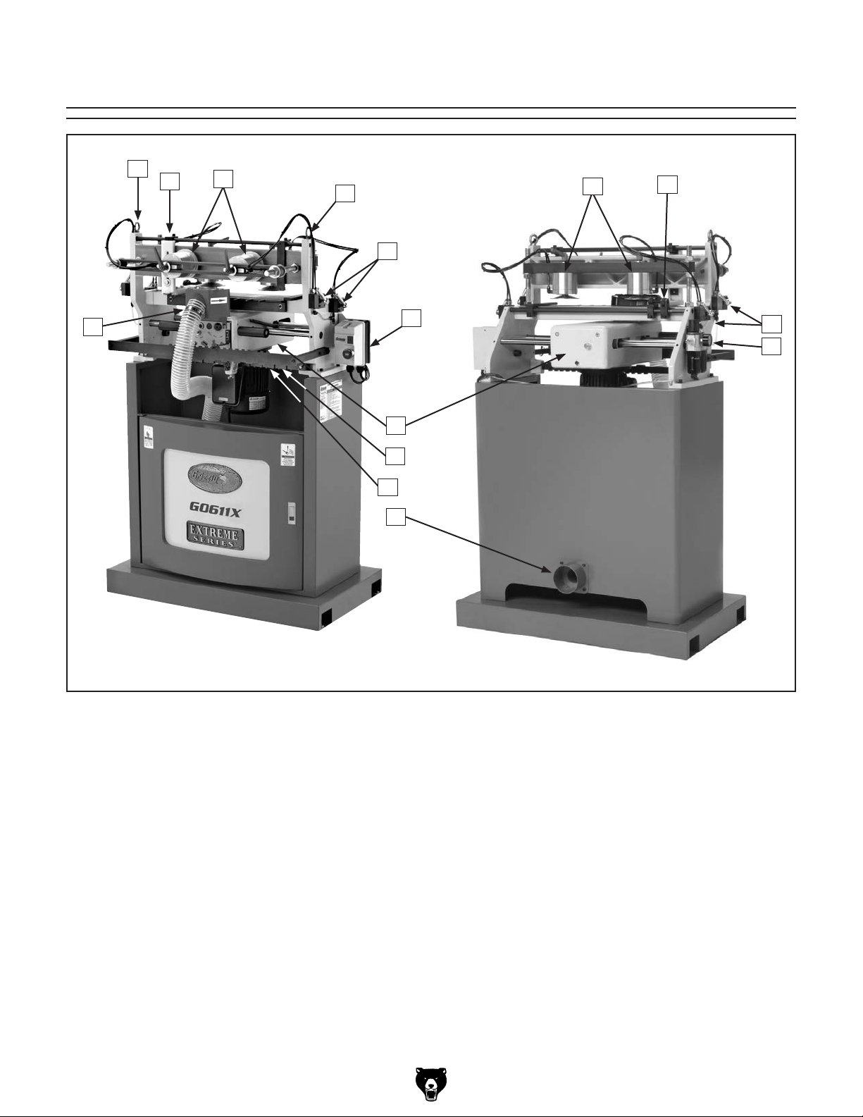
Identification
A
B
H
C
A
D
G
J
K
L
M
E
F
D
I
Model G 0611X (Mfd. 07/15)
A. Eye Bolts for Lifting
B. Vertical Workpiece Fence
C. Vertical Workpiece Clamps
D. Clamp Activation Handles
E. Horizontal Workpiece Clamps
F. Horizontal Workpiece Fence
G. Magnetic Switch
H. Guard
I. Air Supply Unit
J. Headstock
K. Indicator Plate
L. Template Bar
M. Dust Port 4"
-3-
Page 6

Customer Service #: (570) 546-9663 · To Order Call: (800) 523-4777 · Fax #: (800) 438-5901
MODEL G0611X
EXTREME SERIES DOVETAIL MACHINE
Product Dimensions:
Weight ...........................................................................................................................................................................440 lbs.
Width (side-to-side) x Depth (front-to-back) x Height .................................................................... 38-5/8 x 26-1/2 x 56-7/8 in.
Table Height ..............................................................................................................................................................46-7/16 in.
Table Size ..................................................................................................................................................... 24 W x 7-3/4 L in.
Footprint (Length/Width) ......................................................................................................................................37 x 21-1/4 in.
Shipping Dimensions:
Content .......................................................................................................................................................................... Machine
Weight ............................................................................................................................................................................539 lbs.
Length x Width x Height ........................................................................................................................ 29-5/8 x 42 x 63-5/8 in.
Electrical:
Power Requirement ...............................................................................................................110V/220V, Single-Phase, 60 Hz
Prewired Voltage ................................................................................................................................................................ 220V
Full-Load Current Rating .....................................................................................................................10A at 110V, 5A at 220V
Included Plug Type ...............................................................................................................................................5-15 for 110V
Recommended Plug Type ....................................................................................................................................6-15 for 220V
Motor:
Type ......................................................................................................................................... TEFC Capacitor-Start Induction
Horsepower .........................................................................................................................................................................1 HP
Voltage ......................................................................................................................................................................110V/220V
Prewired Voltage ................................................................................................................................................................ 220V
Phase ................................................................................................................................................................................Single
Amps ...............................................................................................................................................................................10A/5A
Speed .........................................................................................................................................................................3450 RPM
Cycle ................................................................................................................................................................................. 60 Hz
Bearings .............................................................................................................................Shielded & Permanently Lubricated
Capacities:
Number of Spindles ..................................................................................................................................................................1
Spindle Speed .........................................................................................................................................................18,500 RPM
Dovetail Shank Diameter .................................................................................................................................... 1/2 in. (12mm)
Dovetail Bit ...........................................................................................................................Angle 10° x 5/8 in. L Single Cutter
Dovetail Templates ................................................................................................................................... 1, 1-1/2 , 2, 2-1/2 in.
Maximum Dovetail Height .................................................................................................................................................3/4 in.
Minimum Dovetail Height ................................................................................................................................................3/16 in.
Maximum Workpiece Thickness ....................................................................................................................................2-3/8 in.
Minimum Workpiece Thickness ....................................................................................................................................13/32 in.
Maximum Workpiece Size .......................................................................................................................... 16-1/2
Minimum Workpiece Size ......................................................................................................................... 2-3/8
Construction:
Table Frame .................................................................................................................................... Precision-Ground Cast Iron
Carriage ......................................................................................................................................................................Aluminum
Stand .............................................................................................................................................................. Pre-Formed Steel
Spindle Bearings ............................................................................................................ Permanently Lubricated Ball Bearings
-4-
Model G 0611X (Mfd. 07/15)
W x 59 L in.
W x 7-7/8 L in.
Page 7

Slide Way ..................................................................................................................Hardened Ground Chromed Round Steel
Sliding Guide ....................................................................................................................................Ball Bearing Linear Guides
Other Specifications:
Features:
Country of Origin ............................................................................................................................................................. Taiwan
Warranty ........................................................................................................................................................................... 1 Year
Serial Number Location ................................................................................................................ ID Label on Side of Machine
ISO 9001 Factory ................................................................................................................................................................... No
Certified by a Nationally Recognized Testing Laboratory (NRTL) ......................................................................................... No
Micro-Adjustable Spindle Head for Precision Control of Dovetail "Fit"
Material Stops for Quick Workpiece Positioning
Dual Pneumatic Clamping System for Quickly Loading/Unloading Workpieces
4" Dust Port
Spring Loaded Carriage for Smooth Cutting
Soft Grip Control Handles
Model G 0611X (Mfd. 07/15)
-5-
Page 8
SECTION 1: SAFETY
For Your Own Safety, Read Instruction
Manual Before Operating This Machine
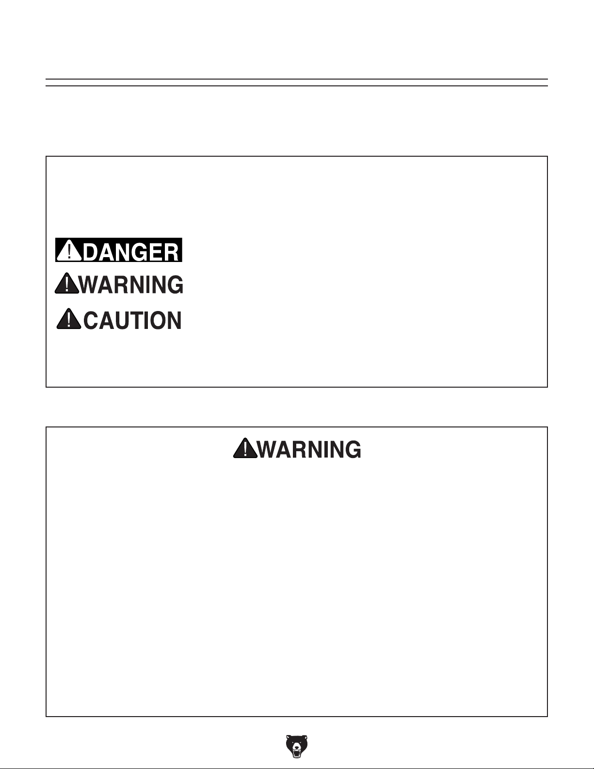
The purpose of safety symbols is to attract your attention to possible hazardous conditions.
This manual uses a series of symbols and signal words intended to convey the level of importance of the safety messages. The progression of symbols is described below. Remember that
safety messages by themselves do not eliminate danger and are not a substitute for proper
accident prevention measures. Always use common sense and good judgment.
Indicates an imminently hazardous situation which, if not avoided,
WILL result in death or serious injury.
Indicates a potentially hazardous situation which, if not avoided,
COULD result in death or serious injury.
Indicates a potentially hazardous situation which, if not avoided,
MAY result in minor or moderate injury. It may also be used to alert
against unsafe practices.
This symbol is used to alert the user to useful information about
NOTICE
proper operation of the machine.
Safety Instructions for Machinery
OWNER’S MANUAL. Read and understand this
owner’s manual BEFORE using machine.
TRAINED OPERATORS ONLY. Untrained operators have a higher risk of being hurt or killed.
Only allow trained/supervised people to use this
machine. When machine is not being used, disconnect power, remove switch keys, or lock-out
machine to prevent unauthorized use—especially
around children. Make workshop kid proof!
DANGEROUS ENVIRONMENTS. Do not use
machinery in areas that are wet, cluttered, or have
poor lighting. Operating machinery in these areas
greatly increases the risk of accidents and injury.
MENTAL ALERTNESS REQUIRED. Full mental
alertness is required for safe operation of machinery. Never operate under the influence of drugs or
alcohol, when tired, or when distracted.
ELECTRICAL EQUIPMENT INJURY RISKS. You
can be shocked, burned, or killed by touching live
electrical components or improperly grounded
machinery. To reduce this risk, only allow qualified
service personnel to do electrical installation or
repair work, and always disconnect power before
accessing or exposing electrical equipment.
DISCONNECT POWER FIRST.
nect machine from power supply BEFORE making
adjustments, changing tooling, or servicing machine.
This prevents an injury risk from unintended startup
or contact with live electrical components.
EYE PROTECTION. Always wear ANSI-approved
safety glasses or a face shield when operating or
observing machinery to reduce the risk of eye
injury or blindness from flying particles. Everyday
eyeglasses are NOT approved safety glasses.
Always discon-
-6-
Model G 0611X (Mfd. 07/15)
Page 9

WEARING PROPER APPAREL. Do not wear
clothing, apparel or jewelry that can become
entangled in moving parts. Always tie back or
cover long hair. Wear non-slip footwear to reduce
risk of slipping and losing control or accidentally
contacting cutting tool or moving parts.
HAZARDOUS DUST. Dust created by machinery
operations may cause cancer, birth defects, or
long-term respiratory damage. Be aware of dust
hazards associated with each workpiece material. Always wear a NIOSH-approved respirator to
reduce your risk.
HEARING PROTECTION. Always wear hearing protection when operating or observing loud
machinery. Extended exposure to this noise
without hearing protection can cause permanent
hearing loss.
REMOVE ADJUSTING TOOLS. Tools left on
machinery can become dangerous projectiles
upon startup. Never leave chuck keys, wrenches,
or any other tools on machine. Always verify
removal before starting!
USE CORRECT TOOL FOR THE JOB. Only use
this tool for its intended purpose—do not force
it or an attachment to do a job for which it was
not designed. Never make unapproved modifications—modifying tool or using it differently than
intended may result in malfunction or mechanical
failure that can lead to personal injury or death!
AWKWARD POSITIONS. Keep proper footing
and balance at all times when operating machine.
Do not overreach! Avoid awkward hand positions
that make workpiece control difficult or increase
the risk of accidental injury.
CHILDREN & BYSTANDERS. Keep children and
bystanders at a safe distance from the work area.
Stop using machine if they become a distraction.
GUARDS & COVERS. Guards and covers reduce
accidental contact with moving parts or flying
debris. Make sure they are properly installed,
undamaged, and working correctly BEFORE
operating machine.
FORCING MACHINERY. Do not force machine.
It will do the job safer and better at the rate for
which it was designed.
NEVER STAND ON MACHINE. Serious injury
may occur if machine is tipped or if the cutting
tool is unintentionally contacted.
STABLE MACHINE. Unexpected movement during operation greatly increases risk of injury or
loss of control. Before starting, verify machine is
stable and mobile base (if used) is locked.
USE RECOMMENDED ACCESSORIES. Consult
this owner’s manual or the manufacturer for recommended accessories. Using improper accessories will increase the risk of serious injury.
UNATTENDED OPERATION. To reduce the
risk of accidental injury, turn machine OFF and
ensure all moving parts completely stop before
walking away. Never leave machine running
while unattended.
MAINTAIN WITH CARE. Follow all maintenance
instructions and lubrication schedules to keep
machine in good working condition. A machine
that is improperly maintained could malfunction,
leading to serious personal injury or death.
DAMAGED PARTS. Regularly inspect machine
for damaged, loose, or mis-adjusted parts—or
any condition that could affect safe operation.
Immediately repair/replace BEFORE operating
machine. For your own safety, DO NOT operate
machine with damaged parts!
MAINTAIN POWER CORDS. When disconnecting cord-connected machines from power, grab
and pull the plug—NOT the cord. Pulling the cord
may damage the wires inside. Do not handle
cord/plug with wet hands. Avoid cord damage by
keeping it away from heated surfaces, high traffic
areas, harsh chemicals, and wet/damp locations.
EXPERIENCING DIFFICULTIES. If at any time
you experience difficulties performing the intended operation, stop using the machine! Contact our
Technical Support at (570) 546-9663.
Model G 0611X (Mfd. 07/15)
-7-
Page 10
DISCONNECT POWER BEFORE ANY
Additional Safety for Dovetail Machines
GUARD. The guard helps protect the operator
from the spinning cutter and flying debris during
operation. Never operate the dovetail machine or
allow it to be connected to power when the guard
is removed or serious personal injury may occur.
SAFETY GLASSES. Even with the guard in place,
chips may eject from the machine. Operator and
bystanders MUST wear safety glasses to prevent
eye injuries/
CLAMP PRESSURE. Improperly clamped stock
may be ejected from the rear of the machine during operation. Check clamping pressure by trying to move the clamped workpiece by hand—a
properly clamped workpiece will not move when
tugged. Improper clamping pressure with pneumatic clamps is most often caused by the clamp
bracket not being adjusted parallel to the table or
the air pressure being regulated too low at the air
supply unit.
ADJUSTMENTS. Setting up this machine
requires the operator to work near the exposed
cutter. Always disconnect power BEFORE making adjustments or serious personal injury may
occur.
LOOSE CUTTER. Starting the machine with
a loose cutter may eject the cutter from the
machine at a high rate of speed, causing serious
personal injury to the operator or bystanders.
Always double-check that the cutter is tight after
adjusting.
REMOVE ADJUSTMENT TOOLS. Starting
the machine with a wrench left in the spindle
adjustment screw can result in serious personal
injury. Always remove any wrenches or other
adjustment tools from the machine after adjustments have been made and before starting the
machine.
CUTTER STARTING POSITION. Starting the
machine with the cutter against a workpiece or
fence may eject debris from the machine and
most likely will ruin the workpiece or cutter. Move
the cutter clear of any contact before starting the
machine!
Like all machinery there is potential danger
when operating this machine. Accidents are
frequently caused by lack of familiarity or
failure to pay attention. Use this machine
with respect and caution to lessen the possibility of operator injury. If normal safety
precautions are overlooked or ignored, serious personal injury may occur.
DUST COLLECTION. Using dust collection
when operating this machine greatly reduces flying debris and fine airborne dust, which reduces
the risk of personal injury form these hazards.
Always use a dust collection system when operating this machine.
No list of safety guidelines can be complete.
Every shop environment is different. Always
consider safety first, as it applies to your
individual working conditions. Use this and
other machinery with caution and respect.
Failure to do so could result in serious personal injury, damage to equipment, or poor
work results.
-8-
Model G 0611X (Mfd. 07/15)
Page 11

SECTION 2: POWER SUPPLY
Before installing the machine, consider the availability and proximity of the required power supply
circuit. If an existing circuit does not meet the
requirements for this machine, a new circuit must
be installed. To minimize the risk of electrocution,
fire, or equipment damage, installation work and
electrical wiring must be done by an electrician or
qualified service personnel in accordance with all
applicable codes and standards.
Electrocution, fire, or
equipment damage may
occur if machine is not
correctly grounded and
connected to the power
The full-load current rating is the amperage a
machine draws at 100% of the rated output power.
On machines with multiple motors, this is the
amperage drawn by the largest motor or sum of all
motors and electrical devices that might operate
at one time during normal operations.
The full-load current is not the maximum amount
of amps that the machine will draw. If the machine
is overloaded, it will draw additional amps beyond
the full-load rating.
If the machine is overloaded for a sufficient length
of time, damage, overheating, or fire may result—
especially if connected to an undersized circuit.
To reduce the risk of these hazards, avoid overloading the machine during operation and make
sure it is connected to a power supply circuit that
meets the specified circuit requirements.
For your own safety and protection of
Note: Circuit requirements in this manual apply to
a dedicated circuit—where only one machine will
be running on the circuit at a time. If machine will
be connected to a shared circuit where multiple
machines may be running at the same time, consult an electrician or qualified service personnel to
ensure circuit is properly sized for safe operation.
A power supply circuit includes all electrical
equipment between the breaker box or fuse panel
in the building and the machine. The power supply circuit used for this machine must be sized to
safely handle the full-load current drawn from the
machine for an extended period of time. (If this
machine is connected to a circuit protected by
fuses, use a time delay fuse marked D.)
This machine is prewired to operate on a power
supply circuit that has a verified ground and meets
the following requirements:
Availability
supply.
Full-Load Current Rating
Circuit Information
property, consult an electrician if you are
unsure about wiring practices or electrical
codes in your area.
Full-Load Current Rating at 110V ...... 10 Amps
Full-Load Current Rating at 220V ...... 5 Amps
Model G 0611X (Mfd. 07/15)
Circuit Requirements for 220V
Nominal Voltage .........208V, 2 20V, 23 0V, 240V
Cycle ..........................................................60 Hz
Phase ........................................... Single-Phase
Power Supply Circuit ......................... 15 Amps
Plug/Receptacle ............................. NEMA 6-15
GROUNDED
6-15 RECEPTACLE
Current Carrying Prongs
6-15 PLUG
Grounding Prong
Figure 1. NEMA 6-15 plug and receptacle.
-9-
Page 12
Improper connection of the equipment-grounding
wire can result in a risk of electric shock. The
wire with green insulation (with or without yellow
stripes) is the equipment-grounding wire. If repair
or replacement of the power cord or plug is necessary, do not connect the equipment-grounding
wire to a live (current carrying) terminal.
Check with a qualified electrician or service personnel if you do not understand these grounding
requirements, or if you are in doubt about whether
the tool is properly grounded. If you ever notice
that a cord or plug is damaged or worn, disconnect it from power, and immediately replace it with
a new one.
This machine MUST be grounded. In the event
of certain malfunctions or breakdowns, grounding
reduces the risk of electric shock by providing a
path of least resistance for electric current.
This machine is equipped with a power cord that
has an equipment-grounding wire and a grounding
plug. Only insert plug into a matching receptacle
(outlet) that is properly installed and grounded in
accordance with all local codes and ordinances.
DO NOT modify the provided plug!
Circuit Requirements for 110V
This machine can be converted to operate on a
power supply circuit that has a verified ground
and meets the requirements listed below. (Refer
to Voltage Conversion instructions for details.)
No adapter should be used with plug. If
We do not recommend using an extension cord
with this machine.
cord, only use it if absolutely necessary and only
on a temporary basis.
Extension cords cause voltage drop, which can
damage electrical components and shorten motor
life. Voltage drop increases as the extension cord
size gets longer and the gauge size gets smaller
(higher gauge numbers indicate smaller sizes).
Any extension cord used with this machine must
be in good condition and contain a ground wire
and matching plug/receptacle. Additionally, it must
meet the following size requirements:
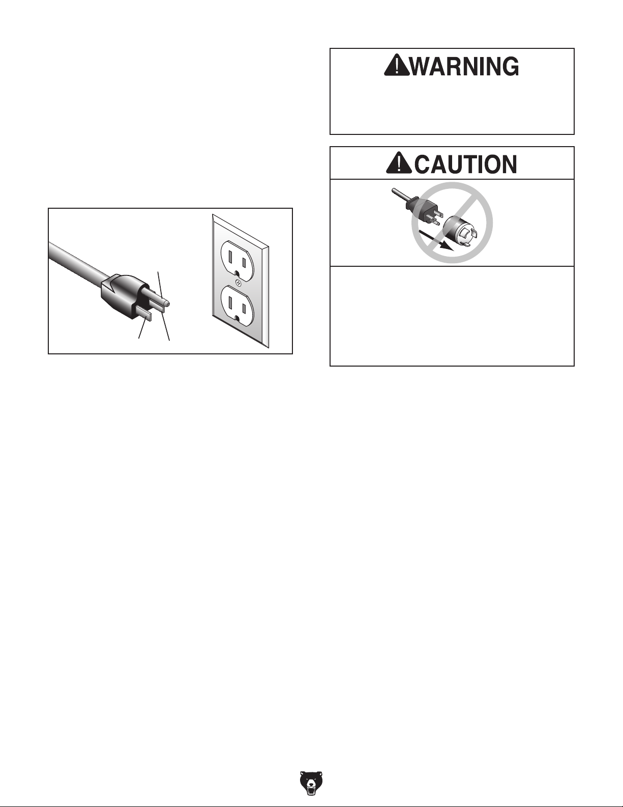
Nominal Voltage .................... 110V, 115V, 12 0V
Cycle ..........................................................60 Hz
Phase ........................................... Single-Phase
Power Supply Circuit ......................... 15 Amps
Plug/Receptacle ............................. NEMA 5-15
GROUNDED
5-15 RECEPTACLE
Grounding Prong
5-15 PLUG
Neutral Hot
Figure 2. Typical 5-15 plug and receptacle.
Serious injury could occur if you connect
machine to power before completing setup
process. DO NOT connect to power until
instructed later in this manual.
plug does not fit available receptacle, or if
machine must be reconnected for use on a
different type of circuit, reconnection must
be performed by an electrician or qualified
service personnel, and it must comply with
all local codes and ordinances.
Grounding Requirements
-10 -
Extension Cords
If you must use an extension
Minimum Gauge Size ...........................14 AWG
Maximum Length (Shorter is Better).......50 ft.
Voltage Conversion
The voltage conversion MUST be performed by
a qualified electrician. To perform the voltage
conversion, install the correct plug and rewire the
motor to the new voltage, according to the provided wiring diagram. If the diagram included on
the motor conflicts with the one in this manual, the
motor may have changed since the manual was
printed. Use the diagram provided on the motor.
Model G 0611X (Mfd. 07/15)
Page 13
SECTION 3: SETUP
The following is a list of items shipped with your
machine. Before beginning setup, lay these items
out and inventory them.
If any non-proprietary parts are missing (e.g. a
nut or a washer), we will gladly replace them; or
for the sake of expediency, replacements can be
obtained at your local hardware store.
This machine was carefully packaged for safe
transport. When unpacking, separate all enclosed
items from packaging materials and inspect them
for shipping damage.
,
please
IMPORTANT:
you are completely satisfied with the machine and
have resolved any issues between Grizzly or the
shipping agent. You MUST have the original pack-
aging to file a freight claim. It is also extremely
helpful if you need to return your machine later.
get help from other people
The following items are needed, but not included,
for the setup/assembly of this machine.
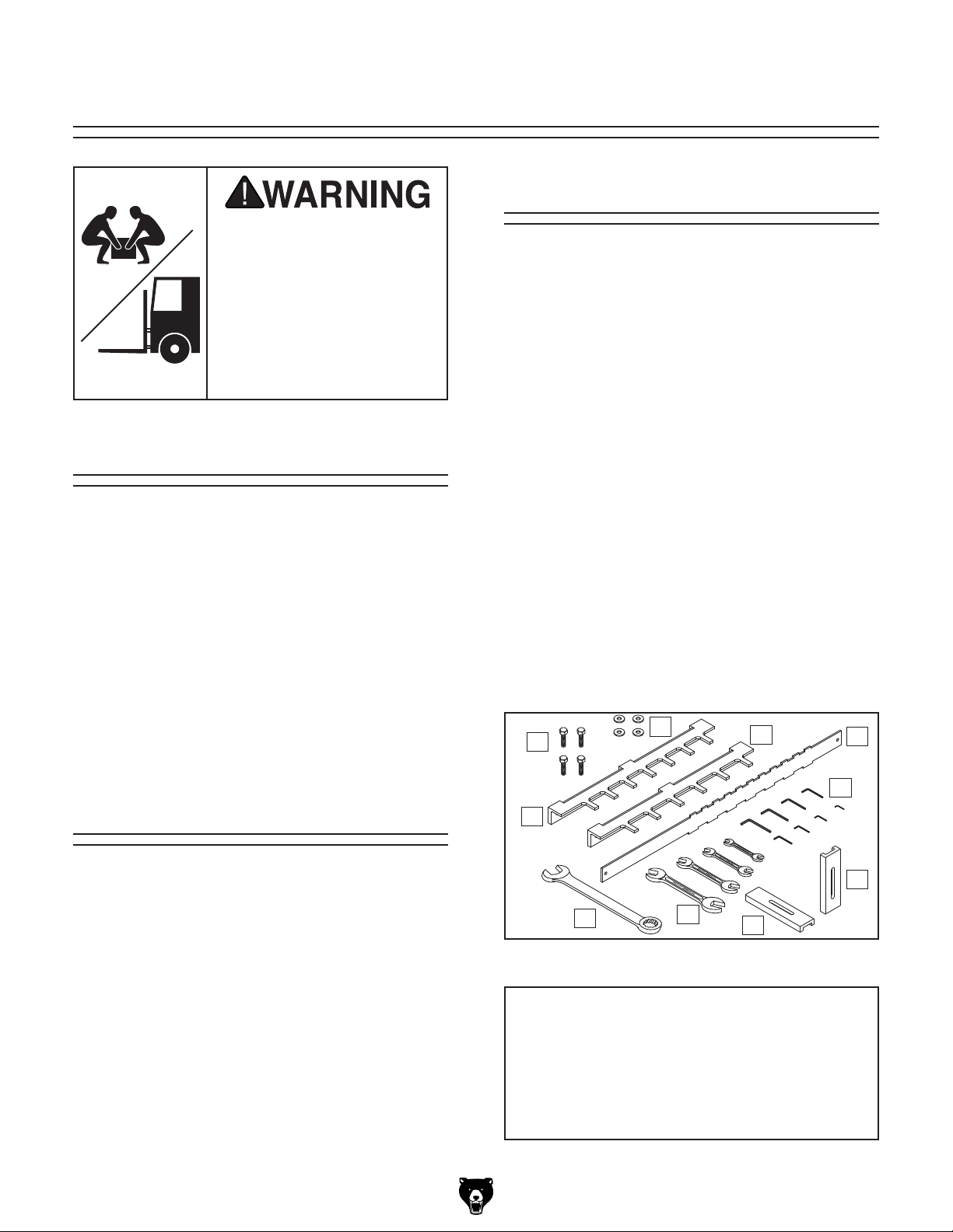
HEAV Y LIF T!
Straining or crushing injury
may occur from improperly
lifting machine or some of
its parts. To reduce this risk,
and use a forklift (or other
lifting equipment) rated for
weight of this machine.
Unpacking
If items are damaged
call us immediately at (570) 546-9663.
Save all packaging materials until
Inventory
Box Inventory (Figure 3): Qty
A. Dovetail Machine (not shown) .................... 1
B. Hex Bolts M8-1.25 x 20 .............................. 4
C. Flat Washers 8mm ..................................... 4
D. Fixed Chaser 2
E. Fixed Chaser 3" .......................................... 1
F. Indicator Bar 1
G. Hex Wrench Set (1.5-6mm) ..................1 Ea.
H. Combo Wrench Set
(8 -10, 11-13, 12-14, and 17-19mm) ........1 Ea.
I. Extra Vertical HDPE Fence ........................ 1
J. Extra Horizontal HDPE Fence .................... 1
K. Open-End Offset Wrench 30mm ................ 1
1
⁄2 " ....................................... 1
1
⁄2 " and 21⁄2 " ......................... 1
Needed for Setup
Description Qty
• Phillips Screwdriver .................................... 1
• Safety Glasses (for each person) .............. 1
• Air Compressor .......................................... 1
• Adjustable Wrench with 1
• Pneumatic Tool Oil ........................4 Ounces
• Dust Collection System .............................. 1
Model G 0611X (Mfd. 07/15)
1
⁄4" Capacity ....... 1
B
D
K
Figure 3. Model G0611X inventory.
C
H
E
J
F
G
I
NOTICE
If you cannot find an item on this list, carefully check around/inside the machine and
packaging materials. Often, these items get
lost in packaging materials while unpacking or they are pre-installed at the factory.
-11-
Page 14
The unpainted surfaces of your machine are
coated with a heavy-duty rust preventative that
prevents corrosion during shipment and storage.
This rust preventative works extremely well, but it
will take a little time to clean.
Be patient and do a thorough job cleaning your
machine. The time you spend doing this now will
give you a better appreciation for the proper care
of your machine's unpainted surfaces.
There are many ways to remove this rust preventative, but the following steps work well in a wide
variety of situations. Always follow the manufacturer’s instructions with any cleaning product you
use and make sure you work in a well-ventilated
area to minimize exposure to toxic fumes.
Before cleaning, gather the following:
• Disposable rags
• Cleaner/degreaser (WD•40 works well)
• Safety glasses & disposable gloves
• Plastic paint scraper (optional)
Basic steps for removing rust preventative:
1.
2.
3.
4.
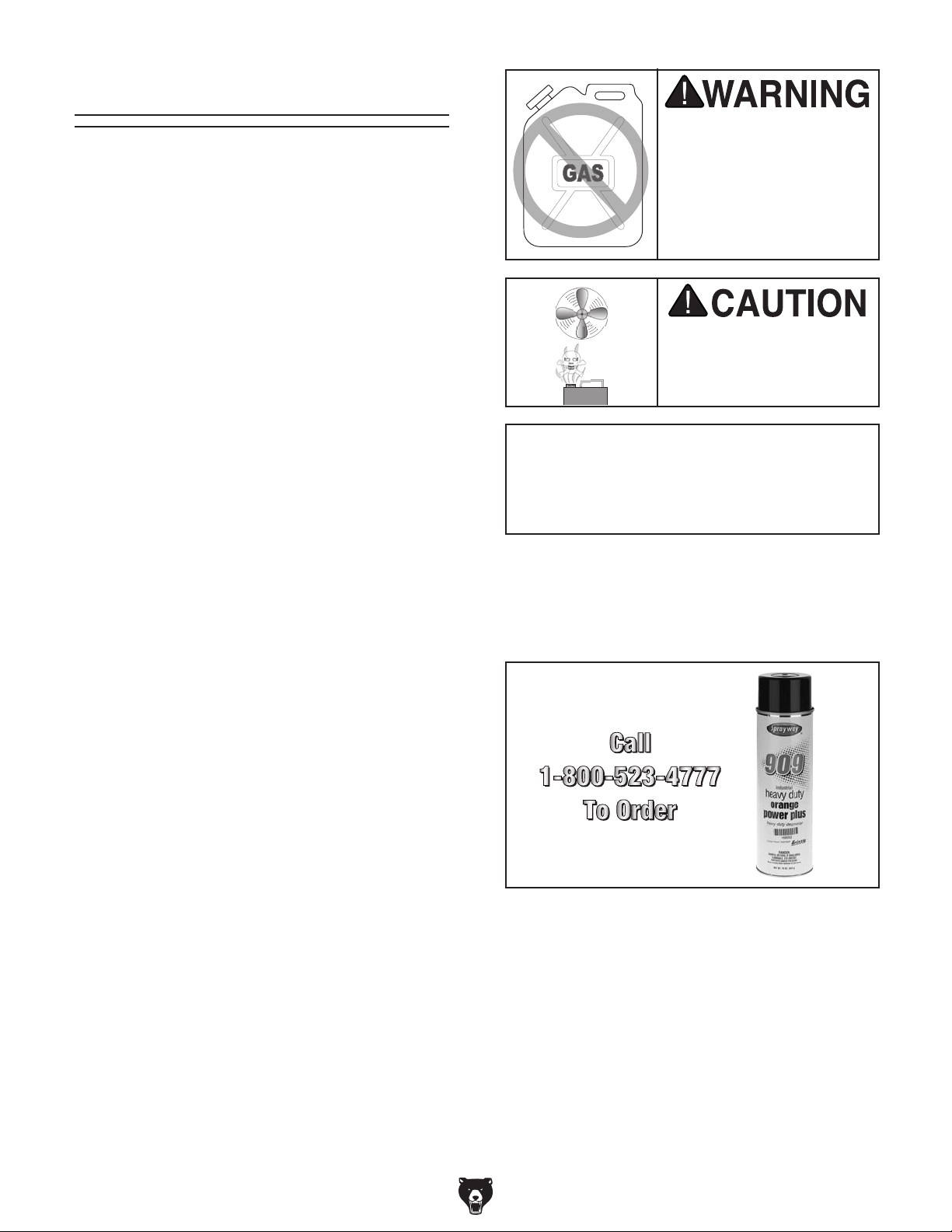
Many cleaning solvents
work in a well-ventilated
Avoid chlorine-based solvents, such as
Cleanup
Gasoline and petroleum
products have low flash
points and can explode
or cause fire if used to
clean machinery. Avoi d
using these products
to clean machinery.
Put on safety glasses.
Coat the rust preventative with a liberal
amount of cleaner/degreaser, then let it soak
for 5–10 minutes.
Wipe off the surfaces. If your cleaner/degreas-
er is effective, the rust preventative will wipe
off easily. If you have a plastic paint scraper,
scrape off as much as you can first, then wipe
off the rest with the rag.
Repeat Steps 2–3 as necessary until clean,
then coat all unpainted surfaces with a quality
metal protectant to prevent rust.
are toxic if inhaled. Only
acetone or brake parts cleaner, that may
damage painted surfaces.
T23692—Orange Power Degreaser
A great product for removing the waxy shipping grease from the non-painted parts of the
machine during clean up.
Figure 4. T23692 Orange Power Degreaser.
area.
NOTICE
-12-
Model G 0611X (Mfd. 07/15)
Page 15
Site Considerations
Weight Load
Refer to the
of your machine. Make sure that the surface upon
which the machine is placed will bear the weight
of the machine, additional equipment that may be
installed on the machine, and the heaviest workpiece that will be used. Additionally, consider the
weight of the operator and any dynamic loading
that may occur when operating the machine.
Space Allocation
Consider the largest size of workpiece that will
be processed through this machine and provide
enough space around the machine for adequate
operator material handling or the installation of
auxiliary equipment. With permanent installations,
leave enough space around the machine to open
or remove doors/covers as required by the maintenance and service described in this manual.
See below for required space allocation.
Physical Environment
Extreme conditions for this type of machinery are
Place this machine near an existing power source.
other hazards. Make sure to leave enough space
Shadows, glare, or strobe effects that may distract
Machine Data Sheet for the weight
Children or untrained people
may be seriously injured by
this machine. Only install in an
access restricted location.
The physical environment where the machine is
operated is important for safe operation and longevity of machine components. For best results,
operate this machine in a dry environment that is
free from excessive moisture, hazardous chemicals, airborne abrasives, or extreme conditions.
generally those where the ambient temperature
range exceeds 41°–104°F; the relative humidity
range exceeds 20%–95% (non-condensing); or
the environment is subject to vibration, shocks,
or bumps.
Electrical Installation
Make sure all power cords are protected from
traffic, material handling, moisture, chemicals, or
around machine to disconnect power supply or
apply a lockout/tagout device, if required.
Lighting
Lighting around the machine must be adequate
enough that operations can be performed safely.
or impede the operator must be eliminated.
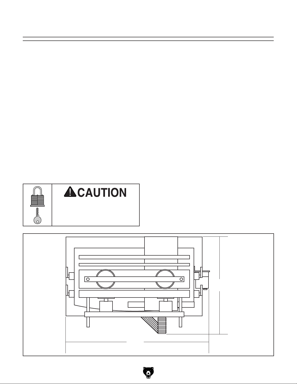
Figure 5. Minimum working clearances.
Model G 0611X (Mfd. 07/15)
261⁄2"
385⁄8"
-13-
Page 16
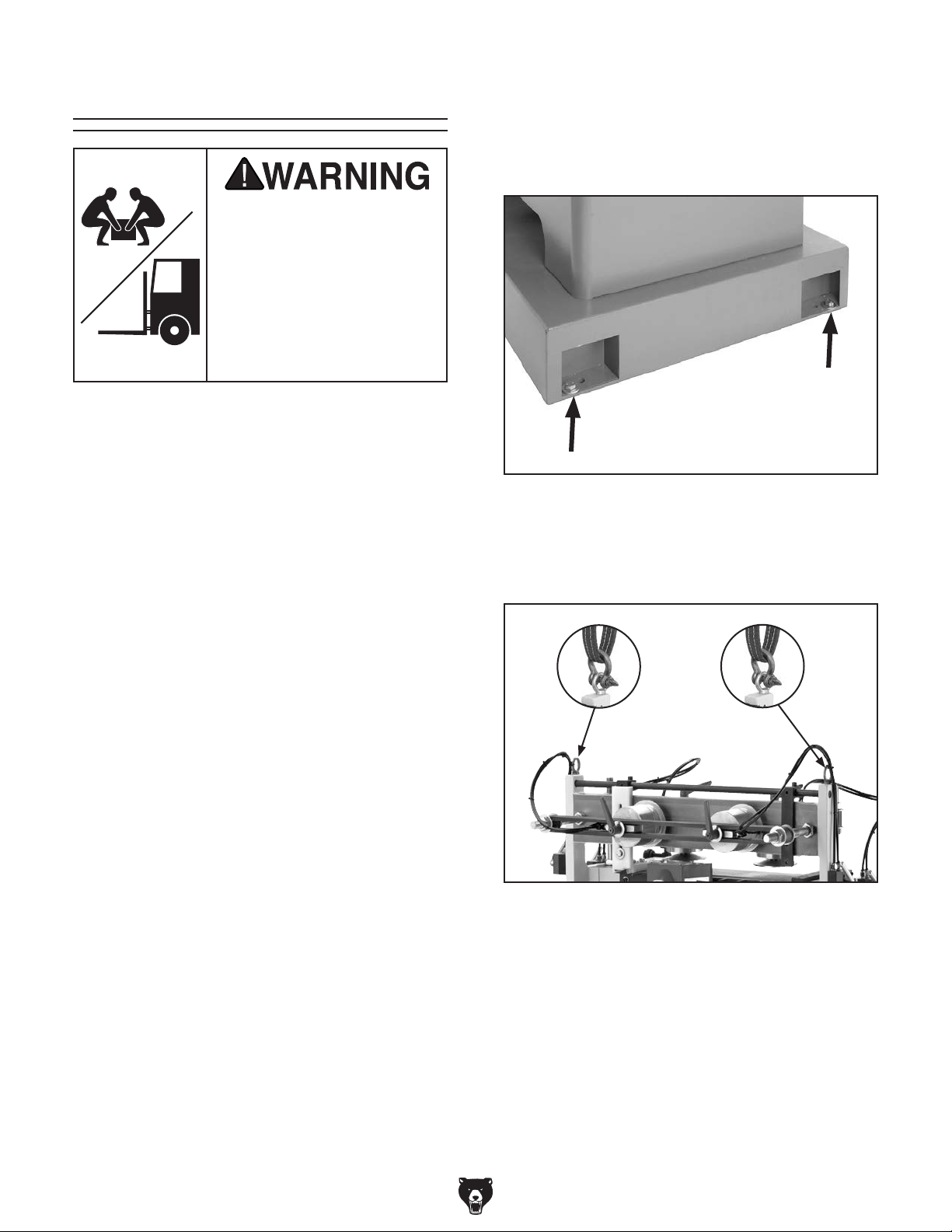
Lifting & Placing
HEAV Y LIF T!
Straining or crushing injury
may occur from improperly
lifting machine or some of
its parts. To reduce this risk,
get help from other people
and use a forklift (or other
lifting equipment) rated for
weight of this machine.
The Model G0611X is designed to be lifted
from two eye bolts mounted near the top of the
machine, on both sides, using a forklift with lifting
straps. The lifting straps can be connected to the
eye bolts with metal shackles.
To lift the Model G0611X with a forklift:
1. Unbolt the base of the dovetail machine from
the shipping pallet (see Figure 6), so it can
be removed for placement.
Figure 6. Example of where machine is bolted to
the pallet (only one side shown).
2. Connect the lifting straps to the eye bolts
using shackles, as shown in Figure 7.
Figure 7. Lifting machine from eyes.
3. Lift the machine and place it in your desired
location.
4. Remove the forklift straps.
-14-
Model G 0611X (Mfd. 07/15)
Page 17

Anchoring to Floor
Anchoring machinery to the floor prevents tipping
or shifting and reduces vibration that may occur
during operation, resulting in a machine that runs
slightly quieter and feels more solid.
If the machine will be installed in a commercial or
workplace setting, or if it is permanently connected (hardwired) to the power supply, local codes
may require that it be anchored to the floor.
If not required by any local codes, fastening the
machine to the floor is an optional step. If you
choose not to do this with your machine, we recommend placing it on machine mounts, as these
provide an easy method for leveling and they have
vibration-absorbing pads.
Lag shield anchors with lag screws (see below)
are a popular way to anchor machinery to a concrete floor, because the anchors sit flush with the
floor surface, making it easy to unbolt and move
the machine later, if needed. However, anytime
local codes apply, you MUST follow the anchoring
methodology specified by the code.
Assembly
Number of Mounting Holes ............................ 4
Diameter of Mounting Hardware ..................
1
⁄2"
Anchoring to Concrete Floors
To assemble the dovetail machine:
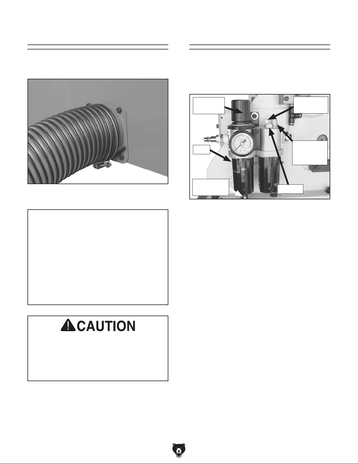
1. Attach the dust hose to the guard as shown
in Figure 9.
Figure 9. Dust hose attached to guard.
Machine Base
Concrete
Figure 8. Popular method for anchoring
machinery to a concrete floor.
Model G 0611X (Mfd. 07/15)
Lag Screw
Flat Washer
Lag Shield Anchor
Drilled Hole
-15-
Page 18
Dust Collection Air Connection
Attach the dust collection hose to the dust port, as
shown in Figure 10.
Figure 10. Dust collection hose attached to dust
port.
Minimum CFM at Dust Port: 400 CFM
Do not confuse this CFM recommendation with
the rating of the dust collector. To determine the
CFM at the dust port, you must consider these
variables: (1) CFM rating of the dust collector,
(2) hose type and length between the dust collector and the machine, (3) number of branches
or wyes, and (4) amount of other open lines
throughout the system. Explaining how to calculate these variables is beyond the scope of
this manual. Consult an expert or purchase a
good dust collection "how-to" book.
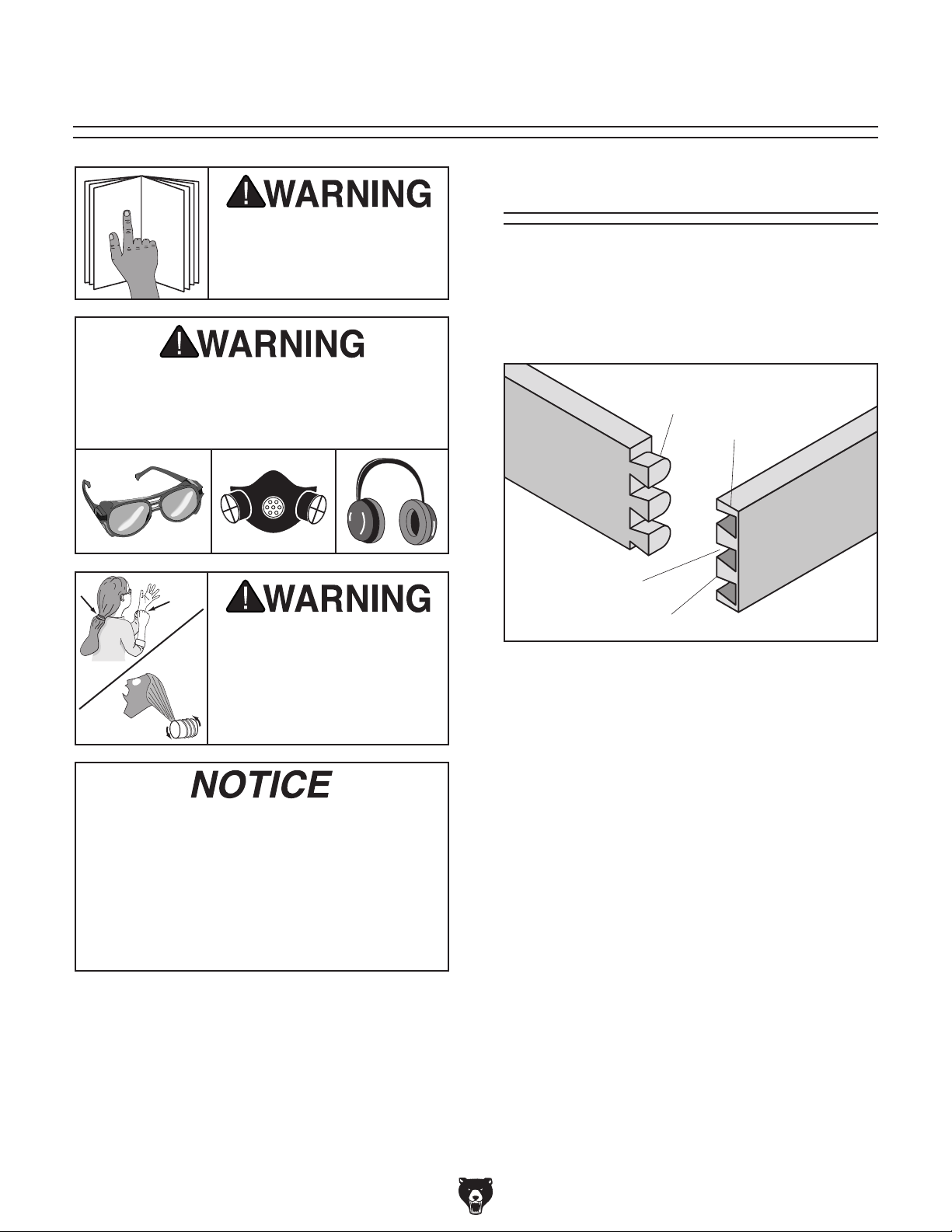
The air supply unit features a regulator, a filter,
and a lubricator (see Figure 11). Each of these
components must be setup properly before operating the machine.
Regulator
Knob
Filter
Drain/Plug
Adjustment
Figure 11. Air supply unit features.
To prepare the air supply unit for operation:
1. Connect your air hose to the air supply unit
with a standard
coupler.
—If air leaks from the bottom of the filter, the
filter may be in "drain" mode. Move the
adjustment at the bottom of the filter to the
other side to put it in "plug" mode.
2. Check the air pressure reading on the gauge.
The correct setting is 40 psi.
1
⁄4" NPT female quick-release
Lubrication
Dial
Lubrication
Rate
Window
Fill Plug
This machine creates substantial amounts
of dust during operation. Breathing airborne dust on a regular basis can result in
permanent respiratory illness. Reduce your
risk by wearing a respirator and capturing
the dust with a dust collection system.
-16 -
—If the setting is correct, skip to Step 4.
—If the setting is not correct, proceed to the
next step.
3. Pull up on the regulator knob, rotate it in the
direction necessary until the gauge reads 40
psi, then push the knob down to lock it.
4. Adjust the lubricator by turning the lubrication dial clockwise until it stops, then
turning it counterclockwise one full turn.
(Further adjustments can be made later as
necessary.)
Model G 0611X (Mfd. 07/15)
Page 19

Test Run
Once assembly is complete, test run the machine
to ensure it is properly connected to power and
safety components are functioning correctly.
If you find an unusual problem during the test run,
immediately stop the machine, disconnect it from
power, and fix the problem BEFORE operating the
machine again. The
table in the
SERVICE section of this manual can help.
DO NOT start machine until all preceding
setup instructions have been performed.
Operating an improperly set up machine
ed results that can lead to serious injury,
Serious injury or death can result from
Troubleshooting
5. Verify that the machine is operating correctly
by turning it ON.
—When operating correctly, the machine
runs smoothly with little or no vibration or
rubbing noises.
— Investigate and correct strange or unusual
noises or vibrations before operating the
machine further. Always disconnect the
machine from power when investigating or
correcting potential problems.
6. Turn the machine OFF.
The test run consists of verifying the following: 1)
The motor powers up and runs correctly, 2) the
stop button safety feature works correctly, and 3)
the motor turns the correct direction (machine is
not wired out of phase).
using this machine BEFORE understanding
its controls and related safety information.
DO NOT operate, or allow others to operate,
machine until the information is understood.
may result in malfunction or unexpect-
death, or machine/property damage.
7. Push the STOP button in to make sure it is
NOT popped out.
8. Press the green ON button.
—If the machine starts, immediately stop the
machine. The switch disabling feature is
not working correctly. This safety feature
must work properly before proceeding with
regular operations. Call Tech Support for
help.
—If the machine does not start, the switch
disabling feature is working as designed.
9. Verify that the cutter is turning the correct
direction by starting the motor, then stopping
the motor while watching the cutter through
the guard window.
— If the cutter turns counterclockwise, it is
turning in the correct direction. Proceed to
Step 10.
To test run the machine:
1. Clear all setup tools away from machine.
2. Press Emergency Stop button in.
3. Connect machine to power by inserting power
cord plug into a matching receptacle.
4. Twist Emergency Stop button clockwise until
it springs out. This resets the switch so the
machine can start.
Model G 0611X (Mfd. 07/15)
— If the cutter turns clockwise, it is turning in
the wrong direction. Contact our Technical
Support department for help.
10. Test the clamps. The clamps should clamp
down when the switch is turned ON and they
should raise up when the switch is turned
OFF.
—If the clamps work as stated, no additional
adjustments are necessary.
— If the clamps do not work as stated, trou-
bleshoot and correct the clamping system.
Contact our Technical Support department
for help.
-17-
Page 20
SECTION 4: OPERATIONS
To reduce your risk of
serious injury, read this
entire manual BEFORE
ing loss can occur while operating this
Keep hair, clothing, and
ing parts at all times.
Entanglement can result
in death, amputation, or
using machine.
Eye injuries, respiratory problems, or hear-
Dovetail Terminology
Take a moment to review the dovetail terminology
shown in Figure 12. These terms will be used
throughout this section and knowing their meaning is important to fully understand the controls of
the machine.
tool. Wear personal protective equipment to
reduce your risk from these hazards.
jewelry away from mov-
severe crushing injuries!
If you are not experienced with this type
of machine, WE STRONGLY RECOMMEND
that you seek additional training outside of
this manual. Read books/magazines or get
formal training before beginning any projects. Regardless of the content in this section, Grizzly Industrial will not be held liable
for accidents caused by lack of training.
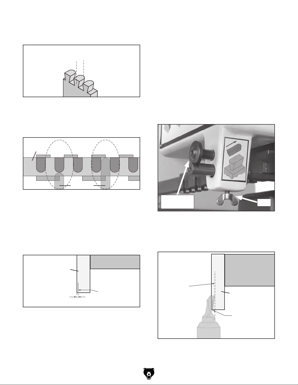
Tail
Half Pin
Drawer
Side
Drawer
Front
Socket
Pin
Figure 12. Dovetail terminology.
-18-
Model G 0611X (Mfd. 07/15)
Page 21

Stock Preparation
Stock preparation is one of the most important
steps for cutting dovetails. Stock must be properly
squared up or the dovetails will not fit in the sockets tightly or evenly. With proper planning and
preparation, you can achieve perfect results.
Stock Size
When selecting your stock, make sure that the
stock size is within the minimum and maximum
dimensions that this machine is capable of processing (see Figure 13).
The first consideration when preparing your stock
is to determine the width (height of drawer). The
dovetail machine includes a 4-sided template with
1
the following sizes: 1", 1
⁄2 ", 2", and 21⁄2 ".
To achieve perfect dovetail spacing from edgeto-edge, the stock width should be a multiple of
1
the template size. For example, when using a 1
template, the stock width should divisible by 1
1
⁄2 ".
⁄2 "
Refer to Figure 14 for more examples.
Template
Size
1"
1
1
⁄2"
2"
1
2
⁄2"
Common Stock Width used with
Template Sizes
3" 4" 5" 6"
1
⁄2" 6" 71⁄2" 9"
4
4" 6" 8" 10"
1
5" 7
⁄2" 10"
Figure 14. Common width sizes used with the
available template sizes.
Maximum
Stock Size
Minimum
Stock Size
59"
77⁄8"
161⁄2"
23⁄8"
Note: If you do not have control over the stock
width, you can still use the machine, but the halfpins on each edge will not be the same size.
23⁄8"
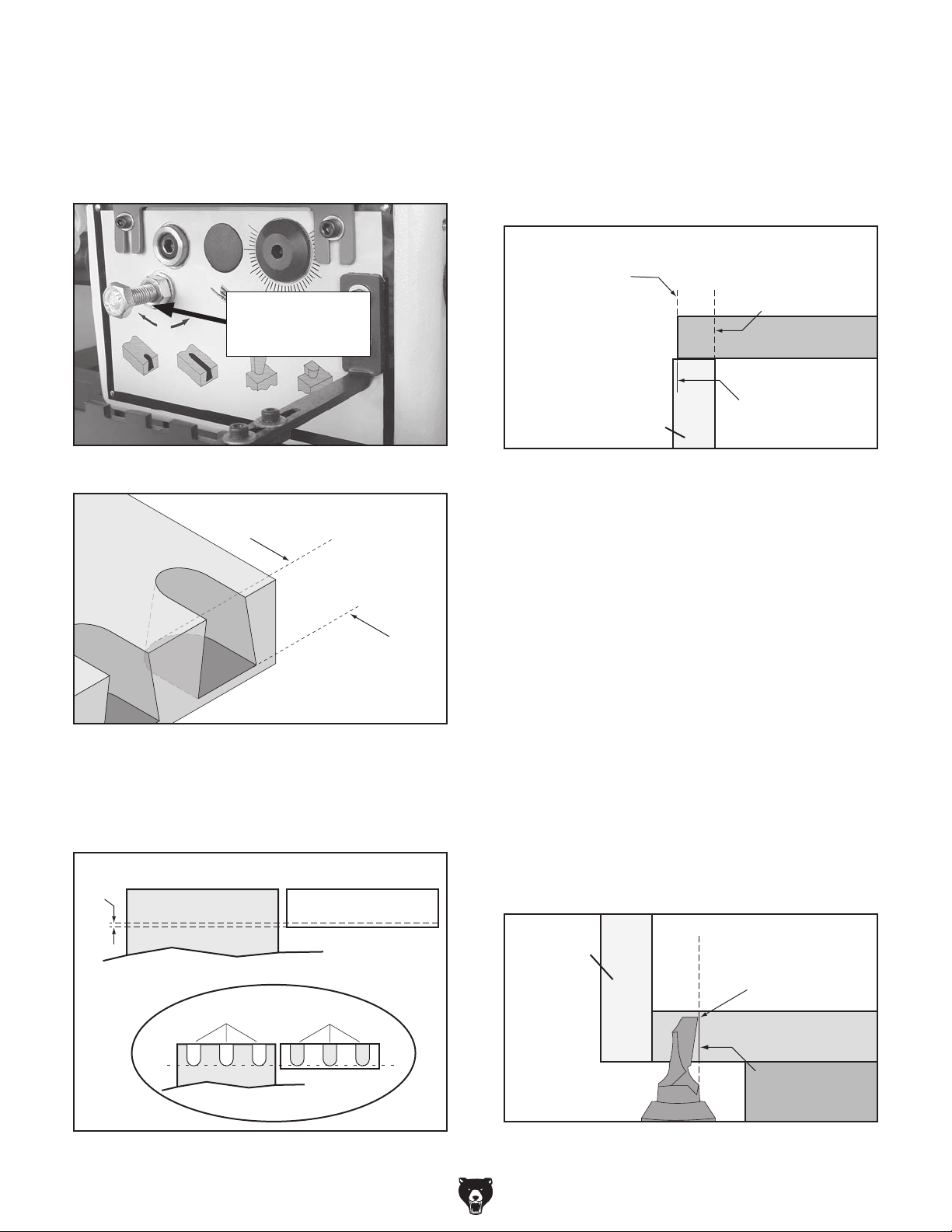
Dado Placement
The dado placement for a drawer bottom is dictated by the size of template you use. In order
for the dado to be hidden when the dovetail
joint is assembled, it must run through a socket.
Figure 15 illustrates this concept.
CORRECT
Dado is not
13
⁄32"
(Slot is Centered in Socket)
Visible
WRONG
Figure 13. Model G0611X stock size limits.
Model G 0611X (Mfd. 07/15)
Dado is Visible
(Slot is not Centered in Socket)
Figure 15. Correct dado placement so dado is
not visible after assembly.
-19 -
Page 22

A general rule of thumb: Cut the center of the
dado half the distance of the template size from
the bottom edge of the stock.
Dovetail Setup
For example, when using a 1" template, center
1
the dado
⁄2 " from the bottom of all four pieces.
This placement ensures that the dado will end up
in the first socket and will not be visible when the
drawer is assembled. Figure 16 shows the ideal
dado placement for each template size.
Template
Size
1"
1
1
⁄2"
2"
1
2
⁄2"
Center of
Dado
from
Bottom
1
⁄2"
3
⁄4"
1"
1
⁄4"
1
EXAMPLE:
1" Template
Stock
Dado Distance
from Bottom
1
⁄2" on
Center
Figure 16. Dado placement for template sizes.
Note: If your stock width is not a multiple of the
template size, this rule of thumb does not apply.
Instead, just cut the dado where you need it and
center the socket placement by eye when setting
up the machine.
Setting up the dovetail machine is a complex procedure that involves trial-and-error and may take
a fair amount of time to complete.
Once you have the machine setup for a particular
stock size, then you can repeat dovetails for that
size indefinitely without additional adjustments.
However, if you change stock size, then you must
repeat this entire setup section.
Before starting any setup, you must prepare
workpieces for one drawer. These must be exactly
the same size as the drawers you will make during your production run. Since trial-and-error is
involved, this first drawer may end up as scrap;
therefore, do not prepare ALL the drawer pieces
for your production run until you have properly
setup the machine and have achieved satisfactory
dovetail joints on your test workpieces.
The setup procedures that follow refer to the
drawer pieces by their position during cutting. To
avoid confusion during the instructions, remember
this:
Layout
After you have dadoed and dimensioned your
stock, layout and mark the drawer pieces, as
shown in Figure 17. This will help you keep track
of the pieces as you cut the dovetails.
BACK
LEFT RIGHT
FRONT
Figure 17. Drawer pieces laid out and marked;
the inside of the drawer pieces are face up.
Drawer Sides (L,R) = Vertical Workpiece
Drawer Front/Back (B, F) = Horizontal Workpiece
Follow the procedures in this section in order to
properly setup your machine for operation.
Setting Clamping Thickness
1. Check the current distance between the
clamps and the tables in relation to your
workpiece thickness.
—If your workpiece fits between the clamps,
then further adjustments are not necessary.
—If your workpiece does not fit between the
clamps, then proceed to Step 2.
-20-
Model G 0611X (Mfd. 07/15)
Page 23

2. Use an adjustable wrench to loosen the
hex nuts shown in Figure 18 away from the
clamp mounting bracket.
Vertical Clamp
Hex Nuts
Horizontal Clamp
Hex Nuts
Figure 18. Hex nuts for adjusting clamping
thicknesses (only one side shown).
3. Slide the clamp mounting bracket so the
clamps provide enough room to move your
workpieces in and out.
Note: Use a ruler to make sure that both sides
are adjusted equally; otherwise, contact area
of the clamp faces will not be uniform, which
could result in the workpieces slipping during
operation.
The template works in tandem with the indicator
plate and the fixed chaser.
Indicator Plate: Since the template bar is underneath the cutting area and away from immediate
operator view, the top edge of the indicator plate
mirrors the position of the tracer pin along the
template bar to help the operator when cutting.
Each indicator plate has two patterns. When
mounted, the top edge of the indicator plate must
match the current side of the template bar that is
being used. Whenever changing the template bar
size, the indicator plate must also be changed.
Use the two mounting cap screws to remove and
change the indicator plate (see Figure 20).
1" and 2"
Indicator Plate
Mounting
Cap Screws
1
1
⁄2" and 21⁄2"
Indicator Plate
4. Tighten the hex nuts against the clamp brack-
ets to hold them in place.
Changing Template Sizes
The template bar (Figure 19) has a different size
dovetail template on each of the four sides. The
size of each template is stamped into that side.
The active template size is always the side that is
facing down. A tracer pin connected to the headstock guides the cutter along the template profile
when cutting.
Template Bar
Figure 19. Template bar.
Figure 20. Indicator plate installation.
Fixed Chaser: The fixed chaser supports the
vertical workpiece, yet allows the cutter to cut the
bottom of the vertical workpiece without hitting
the metal fixed chaser. To prevent the cutter from
contacting the fixed chaser, use the fixed chaser
that corresponds to the template size shown in
Figure 21.
Measuring Fixed Chaser Size
Template Bar Size Use Fixed Chaser Size
1" 2"
1
1
⁄2" 3"
2" 2"
1
2
⁄2" 21⁄2"
Figure 21. Determining correct fixed chaser.
Model G 0611X (Mfd. 07/15)
-21-
Page 24

To change the template bar size:
1. Remove the extension spring shown in
Figure 22, and pull the headstock backward
(toward you) to clear the tracer pin of the template.
Extension Spring
Figure 22. Extension spring (located on the right
side of the headstock).
Setting Fences
The dovetail machine features HDPE (high density polyethylene) plastic fences for both the
horizontal and vertical workpieces (see Figure
24). These fences are cut into during operation to
reduce tear-out.
Vertical Fence
Horizontal Fence
2. Remove the wing screw on each side of the
template bar.
3. Slide the template bar out of the casting and
reinstall it, as shown in Figure 23, so the
desired template size is facing down.
Template Bar
Wing
Screw
Wing
Screw
Figure 23. Template bar installation.
Figure 24. HDPE fences.
The fences should be set so that the dovetails
are evenly distributed across the width of the
workpiece. Setting the fences requires attention to
the "in" and "out" positions of the tracer pin (see
Figure 25). When the tracer pin is in the "in" position, the cutter is cutting the workpiece. When the
tracer is in the "out" position, the cutter is outside
of the workpiece.
Template
Bar
Out
Position
In
Position
Tracer Pin
Figure 25. Tracer pin positions (as viewed from
underneath template bar).
4. Lock the template in place with the wing
screws, then replace the extension spring.
-22-
To set the fences:
1. DISCONNECT MACHINE FROM POWER!
2. Remove the guard.
3. Place the vertical workpiece on the support
bar.
Model G 0611X (Mfd. 07/15)
Page 25

4. Loosen the cap screw on the vertical fence
bracket shown in Figure 26.
Vertical Fence
Bracket
Cap Screw
6. Remember the position of the left-hand edge
of the vertical workpiece on the vertical fence
scale, and move the vertical workpiece out of
the way.
7. Align the right-hand edge of the vertical fence
with the same position on the scale from the
previous step, then lock the vertical fence in
place with the cap screw.
8. Familiarize yourself with the horizontal fence
adjustment components in Figure 28.
Figure 26. Vertical fence adjustment cap screw.
5. Align the left-hand edge of the vertical
workpiece with the centerline of the cutter
when the tracer pin is in the "in" or cutting
position. This position will make the first cut
in the vertical workpiece half the width of the
cutter. Figure 27 illustrates this concept.
Note: If your workpiece width is not evenly
divisible by the template size, then setting the
fences for even cut distribution is a matter of
judging the best possible position by eye.
Vertical
Workpiece
Vertical
Workpiece
Even Cut
Cutter Centerline
Distribution
Aligned
with Edge
Main Adjustment
Micro-Adjust Wheel
Bracket
Cap Screws
Micro-Adjust Bracket
Figure 28. Horizontal fence adjustment
components.
9. Loosen both cap screws shown in Figure 28.
Vertical
Workpiece
Vertical
Workpiece
Uneven Cut
Cutter Centerline
Distribution
NOT Aligned
with Edge
Figure 27. Aligning cutter start location with the
vertical workpiece.
Model G 0611X (Mfd. 07/15)
-23-
Page 26

10. Using the scale on each table as a guide,
adjust the right-hand edge of the horizontal
fence so it is offset half the amount of the
template size being used.
For example, if the template size is 1", offset
1
the right-hand edge of the horizontal fence
⁄2"
from the right-hand edge of the vertical fence,
as shown in Figure 29.
Template
Size
1"
1
1
⁄2"
2"
1
2
⁄2"
Horizontal
Fence
Offset
Distance
1
⁄2"
3
⁄4"
1"
1
⁄4"
1
Offset
Example
for 1"
Template
Vertical
Fence
1
Offset
Horizontal
Fence
⁄2"
Figure 29. Fence offset sizes for each template
size and example offset diagram for 1" template.
1
⁄8" Minimum (recommended)
Horizontal
Workpiece
(end view)
Cutter
Cutter Height
Range
Lowest Point
of Cutter
Figure 31. Understanding the cutter height
range compared to the workpiece.
To set the cutter height:
1. DISCONNECT MACHINE FROM POWER!
2. Place the horizontal workpiece on the hori-
zontal table against the fence, and clamp the
workpiece down.
11. Tighten the cap screw on the micro-adjust
bracket, and use the micro-adjust wheel to
set the horizontal fence in the exact position.
12. Tighten the cap screw on the main adjustment bracket to lock the horizontal fence.
Cutter Height
The cutter height dictates the tail height on the
vertical workpiece and the socket height on the
horizontal workpiece (see Figure 30).
Socket Height
Tail Height
Figure 30. Example of cutter and socket height.
3. Remove one end of the headstock spring,
and move the cutter in front of the horizontal
workpiece.
4. Use a 6mm hex wrench to loosen the
cutterhead lock shown in Figure 32.
Cutter Lock
Cutter Height
Adjustment
Figure 32. Cutter lock and adjustment height.
The cutter height range is restricted by the size
of the cutter (see Figure 31). The lowest point of
the cutting edge on the cutter should never be set
above the bottom of the workpiece.
A taller cutter height is better due to larger tails
and pins, so maximizing the cutter height is preferred in most situations.
-24-
5. Use a 6mm hex wrench to adjust the cutter
1
up or down. Leave at least
⁄8" of material
between the top of the board and the top of
the cutter (see Figure 31).
6. Tighten the cutterhead lock.
Model G 0611X (Mfd. 07/15)
Page 27
Tail Thickness
Figure 33 shows the tail thickness.
Tail Thickness
4. Connect the spring to the headstock.
5. Move the headstock just to the right of the
workpiece, and put the tracer pin in the "out"
position on the template.
6. Stand to the right-hand side of the machine,
and look across the table at the cutter relationship to the vertical workpiece. This viewing position will help you align the cutter with
the workpiece during the next step.
Figure 33. Example of tail thickness.
The tail thickness is controlled by adjusting the
tracer pin when it is in the "out" position on the
template bar, as shown in Figure 34.
Template
Bar
Out
Position
In
Position
Tracer Pin
Figure 34. Tracer pin positions on template.
To set the tail thickness:
1. DISCONNECT MACHINE FROM POWER!
2. Draw a small pencil line on the edge of the
1
vertical workpiece approximately
⁄16" from the
side of the workpiece (see Figure 35).
Note: Familiarize yourself with the tracer pin
controls shown in Figure 36 if this is the first
time you have adjusted it.
Adjustment
Thumbwheel
Lock
Figure 36. Tracer pin controls.
7. Unlock the tracer pin, and adjust the thumb-
wheel as necessary until the bottom of the
cutter is positioned as shown in Figure 37.
Vertical
Workpiece
Table
(Side View)
Pencil
1
⁄16"
Figure 35. Pencil line location on vertical
workpiece.
3. Install the vertical workpiece so the side of
the board closest to the pencil line is facing
out, as shown in Figure 35, and clamp the
workpiece into position against the vertical
fence.
Model G 0611X (Mfd. 07/15)
Line
(Side View)
Cutting edge
rotated to
maximum
point of rotation
from side view.
Cutter
Figure 37. Cutter position for setting tail
thickness (as viewed from the side).
8. Lock the tracer pin.
Table
Vertical
Workpiece
Cutter aligned
with pencil line
at the bottom of
the workpiece.
-25-
Page 28
Cutter Depth Stop
The cutter depth stop adjustment bolt (Figure 38)
dictates the depth of the sockets (Figure 39) by
controlling how far the cutter will cut into the horizontal workpiece.
To set the cutter depth stop:
1. DISCONNECT MACHINE FROM POWER!
2. On a workbench, copy the "Tail Thickness"
dimension from the vertical workpiece to the
horizontal workpiece (Figure 41).
Cutter Depth
Stop Adjustment
Bolt
Figure 38. Cutter depth stop adjustment bolt.
Socket Depth
Figure 39. Socket depth.
The cutter depth should be the same as the tail
thickness, so that when the joint is assembled the
tails are flush with the pins (Figure 40).
Horizontal Workpiece Vertical Workpiece
1
⁄16"
Board Face Board End
...as cut
Sockets
Tails
Edge of
Horizontal
Piece Aligned
w/Pencil Line
Cutter Depth
Pencil Line
Here
Horizontal
Workpiece
(Side View)
Make
Vertical
Workpiece
Figure 41. Marking horizontal workpiece to set
the cutter depth.
3. Clamp vertical workpiece in position on the
machine, then clamp the horizontal workpiece
in place against the vertical workpiece.
4. Move the cutter to the right of the horizontal
workpiece and make sure the tracer pin is in
the "in" position.
5. Rotate the cutter until the leading edge is at
the farthest point in rotation toward the rear of
the machine.
6. From the right-hand side of the machine,
look across the table at the cutter position in
relation to the pencil line.
7. Adjust the cutter depth bolt until the tip of the
cutter aligns with the pencil line (Figure 42),
then tighten the hex nut.
Vertical
Workpiece
Tail Thickness
Pencil Line
Cutter tip at
farthest point
of rotation from
the side view.
Horizontal
Workpiece
Figure 40. Understanding correct cutter depth.
-26-
Pencil Line
(Side View)
Cutter
Figure 42. Cutter position to set cutter depth
stop (viewed from the side).
Model G 0611X (Mfd. 07/15)
Table
Page 29

Testing Machine Setup
RIGHT
or
Testing the setup requires you to make cuts and
adjust the cutter until the dovetail fit is perfect.
Be aware that the drawer you make during this
procedure may end up as scrap. To achieve good
dovetails, you must have prepared your stock as
described in Stock Preparation on Page 19.
To make a test cut:
1. Position the RIGHT workpiece on the vertical
support bar, as shown in the top illustration in
Figure 44 (with the dado positioned out and
opposite the fence), then clamp down the
RIGHT workpiece.
The standard cutting order is shown in Figure 43.
Figure 44 shows the workpieces positioned with
the dadoes close to or away from the fences.
Cut 4:
Position
Dadoes Close
to Fence
LEFT RIGHT
Cut 3:
Position
Dadoes Away
from Fence
BACK
FRONT
Cut 1:
Position
Dadoes Away
from Fence
Cut 2:
Position
Dadoes Close
to Fence
Figure 43. Drawer pieces laid out and marked
inside face up; cutting order and workpiece
position against fences also shown.
LEFT
Vertical
Fence
RIGHT
or
LEFT
Horizontal
Fence
Cuts 1 & 3
FRONT
or
Dadoes Away
BACK
from Fences
FRONT
or
BACK
Dado
Out
Dado
Down
Horizontal
Vertical
Fence
RIGHT
Fence
or
LEFT
FRONT
or
BACK
Cuts 2 & 4
Dadoes Close
to Fences
2. Place the BACK workpiece on the horizontal table, as shown in the top illustration in
Figure 44 (with the dado positioned down
and opposite the fence), then clamp down
the BACK workpiece. The bottom of both
workpieces should be flush with each other
and both workpieces should be firmly against
their respective fences.
3. Position the cutter so it is not touching the
fences or workpieces.
4. INSTALL AND SECURE THE GUARD!
5. Connect the machine to the power source.
6. Make the test cut as described below, but
read all of the steps before starting, so you
do not have to stop after you begin cutting:
a. Start the cut on the left-hand side of the
vertical piece (half of the cutter will cut
into the plastic fences), then carefully follow the template from left-to-right, making sure the tracer pin maintains contact
with the template (otherwise unnecessary tear-out will occur).
b. After clearing the workpieces, do a clean-
up pass by bringing the headstock back
the opposite direction and following the
template from right-to-left.
c. Turn the machine OFF, and position
the cutter clear of the workpieces and
fences.
Dado
Out
Dado
Down
Figure 44. Workpiece positions for cuts.
Model G 0611X (Mfd. 07/15)
-27-
Page 30

7. Remove the workpieces from the machine
and test fit the dovetail joint.
8. Carefully examine how the tails fit into the
sockets. The tails should fit into the sockets
tightly and both workpieces should be flush
with each other. Typically, fine-tuning the
dovetail joint fit requires balancing socket
depth and the cutter adjustment, as follows:
—If the workpieces do not fit together or if the
fit is too tight, then adjust the cutter to take
a larger cut and repeat "Cut 1."
—If the workpieces fit together too loosely,
then adjust the cutter to take a smaller cut
and do "Cut 2."
—If the tails fit easily side-to-side into the
sockets, but do not go down far enough,
adjust the socket depth deeper.
—If the tails fit easily side-to-side into the
sockets, but go too far down, adjust the
socket depth shallower.
To adjust the cutter:
1. DISCONNECT MACHINE FROM POWER!
2. Remove the guard.
3. Use a 4mm hex wrench to loosen the two set
screws on the spindle just enough to allow
the cutter to rotate. (Loosening the two set
screws too much may cause the cutter to
drop down in the spindle and throw off other
adjustments.)
4. Rotate the cutter inside the spindle as necessary to take a smaller or larger cut (see
Figure 46). Use the lowest point in the cutter
groove to keep track of the cutter position
during adjustments.
Lowest
Point
of Cutter
Groove
Adjusting Cutter
The cutter rotates eccentrically in the spindle,
which allows it to be adjusted to control the dovetail joint "fit."
Two set screws hold the cutter in position and a
spindle scale is provided for monitoring the cutter
position during adjustments. Figure 45 shows the
set screws and spindle scale.
Scale
(-)
Take a
smaller cut
(-)
Figure 46. Understanding cutter adjustments.
5. Tighten the two set screws to secure the cut-
ter in place.
6. Make sure the spring is connected to the
headstock.
7. Install the guard.
8. Test the cutter adjustment by making a cut.
9. Repeat cutter adjustments as necessary until
the fit is satisfactory. ALWAYS DISCONNECT
POWER BEFORE ADJUSTING CUTTER!
(+)
(+)
Take a
larger cut
Set Screws
Figure 45. Cutter adjustment controls.
-28-
Model G 0611X (Mfd. 07/15)
Page 31

SECTION 5: ACCESSORIES
Installing unapproved accessories may
order online at www.grizzly.com or call 1-800-523-4777
cause machine to malfunction, resulting in
serious personal injury or machine damage.
To reduce this risk, only install accessories
recommended for this machine by Grizzly.
NOTICE
Refer to our website or latest catalog for
additional recommended accessories.
G0777—1.5 HP Ultra-Quiet Cyclone Dust Collector
Where most dust collectors this size operate at a
minimum of 80-82 dB, the G0777 can collect even
the biggest shavings without exceeding 70–72 dB
due to its slow-speed motor and large impeller.
Features a compact profile on a sturdy mobile
frame, a pleated filter system, an internal filtercleaning brush system, 880 CFM airflow, a builtin remote control switch, and a mobile 35-gallon
collection drum.
G7314Z—Heavy-Duty Mobile Base
Make your machine mobile with this popular
patented mobile base. The unique outrigger type
increases stability and lowers machine height.
This heavy duty mobile base is rated for up to a
700 lb. capacity.
Figure 48. G7314Z Mobile Base.
H9388—Replacement Dovetail Bit
This replacement Dovetail Bit is for the G0610
and G0611X Dovetail Machines.
Figure 49. H9388 Replacement Dovetail Bit.
Figure 47. G0777 Ultra-Quiet Cyclone
Dust Collector.
Model G 0611X (Mfd. 07/15)
-29-
Page 32

order online at www.grizzly.com or call 1-800-523-4777
T10456—Heavy-Duty Anti-Fatigue Mat 3' x 5'
This Heavy-Duty Anti-Fatigue Mat features beveled edges and no-slip tread for safety and
comfort. Open-hole design allows liquid to drain
through, so it's perfect for wet or oily conditions.
Measures 3' wide x 5' long x 3/8" thick.
Figure 50. T10456 Anti-Fatigue Mat.
H4978—Deluxe Earmuffs - 27dB
H4979—Twin Cup Hearing Protector - 29dB
T20446—Classic Earplugs, 200-pair - 31dB
Protect yourself comfortably with a pair of cushioned earmuffs. Especially important if you or
employees operate for hours at a time.
H4978
G5562—SLIPIT
G5563—SLIPIT
G2871—Boeshield
G2870—Boeshield
H3788—G96
H3789—G96
®
1 Qt. Gel
®
12 oz Spray
®
T-9 12 oz Spray
®
®
Gun Treatment 12 oz Spray
®
Gun Treatment 4.5 oz Spray
T-9 4 oz Spray
Figure 52. Recommended products for protect-
ing unpainted cast-iron/steel part on machinery.
G4682—Dry Coating Lube
Spray on saw blades, router bits, shaper cutters even table tops - to form a low-friction coating that
works great, even under high temperature and
pressure. Contains no silicone or oil, so it won’t
stain or damage paint or wood finishes. 9.5 oz.
H4979
Figure 51. Hearing protection.
T20446
Figure 53. G4682 Dry Coating Lube.
-30-
Model G 0611X (Mfd. 07/15)
Page 33
order online at www.grizzly.com or call 1-800-523-4777
H6840—Titebond III - Wood Glue, 1 Gal.
An advanced, proprietary technology that offers
the best possible performance in woodworking
glues, Titebond III uses a waterproof formula that
passes the ANSI/HPVA Type-1 water-resistance
specification and offers superior bond strength,
longer open assembly time, and lower application
temperature. It provides strong initial tack, sands
easily without softening, and is FDA approved for
indirect food contact (cutting boards). The ultimate
in wood glues - ideal for both interior and exterior
applications.
Basic Eye Protection
T20501—Face Shield Crown Protector 4"
T20502—Face Shield Crown Protector 7"
T20503—Face Shield Window
T20451—“Kirova” Clear Safety Glasses
T20452—“Kirova” Anti-Reflective S. Glasses
H7194—Bifocal Safety Glasses 1.5
H7195—Bifocal Safety Glasses 2.0
H7196—Bifocal Safety Glasses 2.5
T20502
T20452
T20503
Figure 54. H6840 Titebond III Wood Glue.
H7194
Figure 55. Assortment of basic eye protection.
T20451
Model G 0611X (Mfd. 07/15)
-31-
Page 34
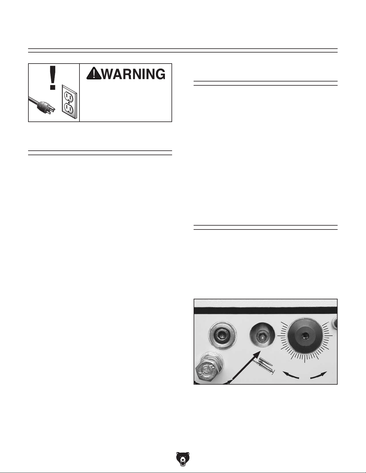
SECTION 6: MAINTENANCE
To reduce risk of shock or
accidental startup, always
disconnect machine from
Cleaning
Cleaning the Model G0611X is relatively easy.
power before adjustments,
maintenance, or service.
Vacuum excess wood chips and sawdust, and
wipe off the remaining dust with a dry cloth. If any
resin has built up, use a resin dissolving cleaner
to remove it.
Schedule
For optimum performance from your machine,
follow this maintenance schedule and refer to any
specific instructions given in this section.
Daily Check (8 Hours)
• Check/tighten cutter set screws.
• Clean debirs/sawdust from clamps to ensure
that they do not interfere with the clamping
ability.
• Clean/vacuum dust buildup from inside cabinet and off motor.
• Unpainted cast-iron portions of the table and
the headstock travel rods should be cleaned
and wiped down with a metal protectant.
• Check/replace damaged power cords or
wires.
• Check/add air tool oil to the air supply unit
lubricator.
• Check/drain the air supply unit water filter.
(Drain by sliding the white shaft to the other
side.)
Protect the unpainted cast iron table by wiping
it clean after every use—this ensures moisture
from wood dust does not remain on bare metal
surfaces. Keep the table rust-free with regular
applications of products like G96
SLIPIT
details).
®
, or Boeshield® T-9 (see Page 29 for more
®
Gun Treatment,
Lubrication
Most of the bearings in the machine are sealed
and lubricated for life.
The spindle has one grease fitting that must be
greased approximately every 40 hours or one
week of regular use (refer to Figure 56). Use high
temperature bearing grease.
Weekly Maintenance (40 Hours)
• Grease the spindle.
Monthly Check (320 Hours)
• Belt tension, damage, or wear.
-32-
Figure 56. Spindle grease fitting located on
headstock control panel.
To grease the spindle, connect the fitting to a
grease gun and give the spindle one pump of
grease.
Model G 0611X (Mfd. 07/15)
Page 35
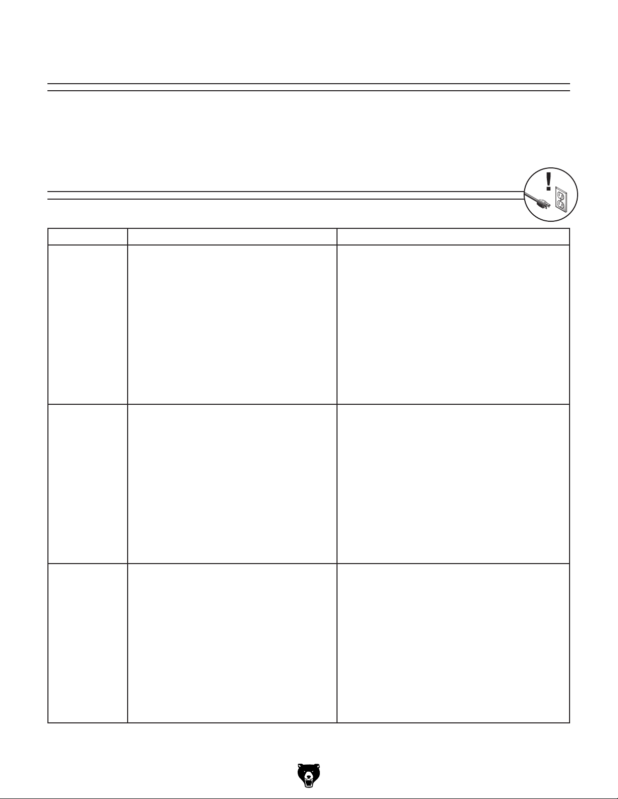
SECTION 7: SERVICE
Review the troubleshooting and procedures in this section if a problem develops with your machine. If
you need replacement parts or additional help with a procedure, call our Technical Support.
gather the serial number and manufacture date of your machine before calling.
Troubleshooting
Motor & Electrical
Symptom Possible Cause Possible Solution
Machine does not
start or a breaker
trips.
Machine stalls or
is underpowered.
Machine has
vibration or noisy
operation.
1. STOP button pushed in, disabling the switch.
2. Plug/receptacle is at fault or wired incorrectly.
3. Start capacitor is at fault.
4. Motor connection wired incorrectly.
5. Power supply is at fault/switched OFF.
6. Motor ON button or ON/OFF switch is at fault.
7. Motor centrifugal switch is at fault.
8. Emergency stop push-panel is stuck/switch is
at fault.
9. Motor windings or motor is at fault.
1. Wrong workpiece material (wood).
2. Feed rate too fast for task.
3. Run capacitor is at fault.
4. Belt slipping.
5. Motor connection is wired incorrectly.
6. Plug/receptacle is at fault.
7. Motor bearings are at fault.
8. Motor has overheated.
9. Motor is at fault.
10. Motor centrifugal switch is at fault.
1. Motor or component is loose.
2. Belt(s) worn or loose.
3. Motor fan is rubbing on fan cover.
4. Pulley is loose.
5. Machine is incorrectly mounted or sits unevenly on floor.
6. Cast iron motor mount loose/broken.
7. Motor or spindle bearings are at fault.
8. Cutter is at fault.
9. Motor centrifugal switch is at fault.
1. Twist STOP button clockwise until it pops out to
enable the switch.
2. Test for good contacts; correct the wiring.
3. Test/replace if faulty.
4. Correct motor wiring connections.
5. Ensure hot lines have correct voltage on all legs and
main power supply is switched ON.
6. Replace faulty ON button or ON/OFF switch.
7. Adjust/replace the centrifugal switch if available.
8. Free push-panel from binding; replace faulty switch.
9. Replace motor.
1. Use wood with correct moisture content, without
glues, and little pitch/resins.
2. Decrease feed rate.
3. Tighten/repair/replace.
4. Replace bad belt and retension (Page 36).
5. Correct motor wiring connections.
6. Test for good contacts; correct the wiring.
7. Test by rotating shaft; rotational grinding/loose shaft
requires bearing replacement.
8. Clean off motor, let cool, and reduce workload.
9. Test/repair/replace.
10. Adjust/replace centrifugal switch if available.
1. Inspect/replace stripped or damaged bolts/nuts, and
re-tighten with thread locking fluid.
2. Inspect/replace belts (Page 36).
3. Replace dented fan cover; replace damaged fan.
4. Tighten pulley set screw.
5. Tighten/replace anchor studs in floor; relocate/shim
machine.
6. Tighten/replace.
7. Test by rotating shaft; rotational grinding/loose shaft
requires bearing replacement.
8. Replace warped, bent, or twisted cutter.
9. Adjust/replace centrifugal switch if available.
Note: Please
Model G 0611X (Mfd. 07/15)
-33-
Page 36

Cutting Operations and Results
Symptom Possible Cause Possible Solution
Workpiece slips or kicks
out during operation.
Cutter cuts slow or does
not cut properly.
Dovetail joint fit is too
tight.
Dovetail joint fit is too
loose.
Tails fit too far into
sockets.
Tails will not fit completely into the sockets.
Tails sit flush with pins
at one end but not the
othe r.
Gaps exist between tails
and pins.
Dado or groove for
drawer bottom visible on
assembled joint.
Dovetails fit together
correctly, but tops/edges
of workpieces are not
flush with each other.
Distribution of dovetails
across assembled joint
is not symmetrical.
1. Low air pressure to clamps.
2. Clamps are adjusted too far away from
the workpiece.
3. Clamp bracket is incorrectly adjusted,
causing the clamps to make uneven
contact with the workpiece.
1. Cutter is dull.
2. Belt is slipping on the pulley.
3. Cutter is rotating clockwise (motor is
wired incorrectly).
1. Cutter is not taking a large enough
cut.
1. Cutter is taking too large of a cut. 1. Adjust the cutter to take a smaller cut (Page 28).
1. Sockets are cut too deep. 1. Adjust the cutter depth stop so the cutter will not cut
1. Cutter is not taking a large enough
cut.
2. Sockets are not cut deep enough.
1. Horizontal workpieces were not positioned square when clamped.
2. Horizontal workpieces were not cut
square or workpieces were not properly
prepared.
1. Vertical workpieces were not positioned
square when clamped.
2. The fixed chaser is not flush with the
horizontal table.
3. Vertical workpieces were not cut square
or workpieces were not properly prepared.
1. Dado cut in the wrong location for the
template being used.
2. Fences set incorrectly.
1. Fences were not offset by exactly half
of the template size being used.
1. Fences are not set correctly to allow
the cutter to start in the proper location.
2. Workpiece width is not divisible by the
template size being used.
1. Increase the air pressure to at least 40 PSI.
2. Adjust clamps closer to the workpiece (Page 20).
3. Adjust the both sides of the clamp bracket and even
distance from the table (Page 20).
1. Replace or sharpen the cutter (Page 35).
2. Tighten belt (Page 33) or replace belt (Page 36).
3. Wire motor so cutter rotates counterclockwise.
1. Adjust the cutter to take a larger cut (Page 28).
as deeply into the horizontal workpiece (Page 26).
1. Adjust the cutter to take a larger cut (Page 28).
2. Adjust the cutter depth stop so the cutter will cut as
deeper into the horizontal workpiece (Page 26).
1. Reclamp the workpiece with emphasis on keeping it
square before and during clamping.
2. Cut new workpieces with emphasis on squaring up
all the boards (Page 19). Check the saw or technique used to cut the boards to ensure squareness.
1. Reclamp the workpiece with emphasis on keeping it
square before and during clamping.
2. Loosen the 3 cap screws securing the fixed chaser,
adjust it flush with the horizontal table, and tighten.
3. Cut new workpieces with emphasis on squaring up
all the boards (Page 19). Check the saw or technique used to cut the boards to ensure squareness.
1. Cut dadoes in the correct location (Page 19).
2. Reset the fences (Page 22).
1. Set the fences so they are offset exactly half of
the distance as the template size being used. For
example, offset the fences
1
1
⁄2" template, etc. Refer to Page 22 for more details.
1. Reset the fences, paying close attention to where
the first cut will be made into the vertical workpiece
(Page 22).
2. Cut new workpieces that are divisible by the template size being used (Page 21); change template
size to be divisible by workpiece (Page 21); or align
the cutter starting point by eye do the best with the
workpiece size you have—results may not be truly
symmetrical.
1
⁄2" for 1" template, 3⁄4" for
-34-
Model G 0611X (Mfd. 07/15)
Page 37

Replacing Cutter
Tensioning Belt
When the cutter gets dull or if it gets damaged, it
must be replaced. Dull cutters can be resharpened
by a professional, but cutters are inexpensive and
easy to replace.
Tools Needed Qty
Hex Wrench 4mm .............................................. 1
To replace the cutter:
1. DISCONNECT MACHINE FROM POWER!
2. Remove the guard.
3. Loosen the two set screws that hold the cut-
ter in the spindle. (The set screws must be
backed out approximately half-way before
the cutter can be removed.)
4. Slide the cutter out and insert the new one.
5. Tighten the two set screws to secure the cut-
ter in place.
A flat belt transfers power from the motor to the
cutter spindle. This belt stretches with use and
periodically needs to be tensioned. If the cutter
lacks power, stops spinning, or cuts slower than
normal, then the belt may need to be tightened.
When properly tensioned, the belt should only
deflect approximately a
from the middle.
Tools Needed Qty
Hex Wrench 6mm .............................................. 1
To tighten the belt:
1. DISCONNECT MACHINE FROM POWER!
2. Loosen the two motor mount cap screws
shown in Figure 57.
1
⁄4" when pushed inward
6. Replace the guard.
NOTICE
The cutter must be re-adjusted after being
replaced to ensure proper cutting results.
Motor Mount Cap Screws
Figure 57. Motor mount cap screw locations.
Model G 0611X (Mfd. 07/15)
-35-
Page 38
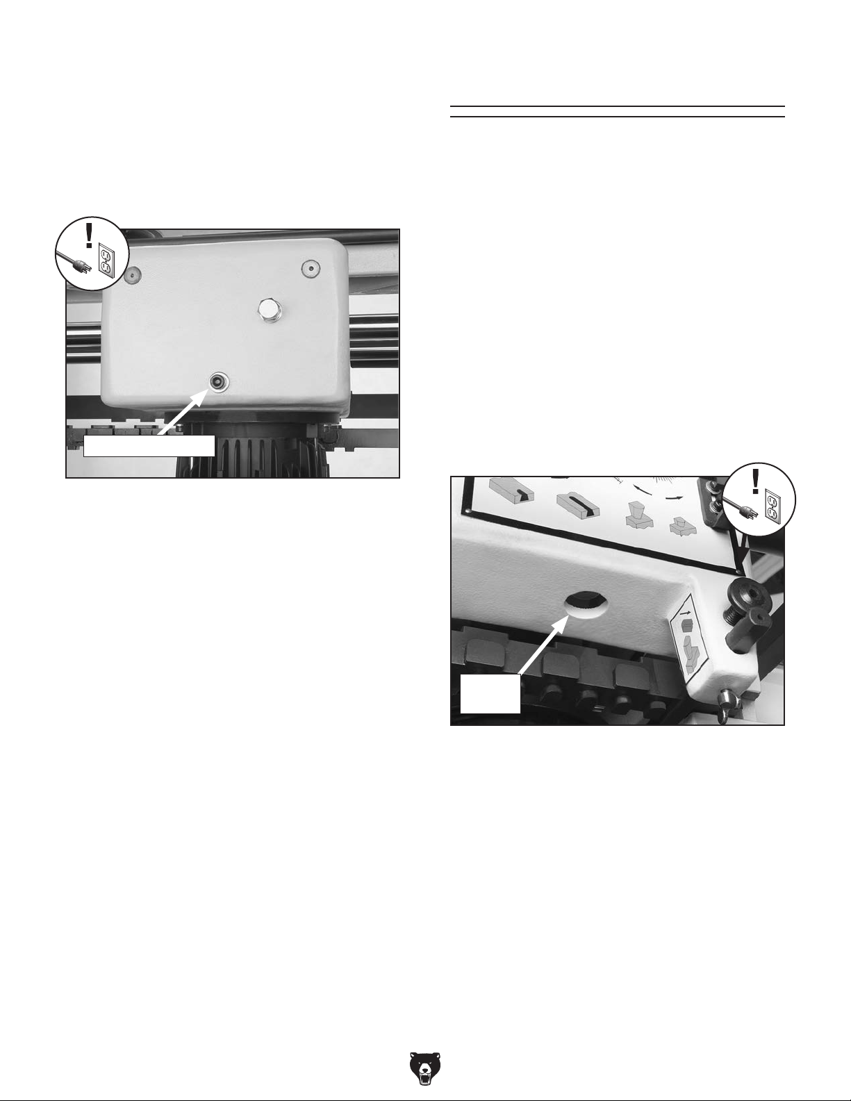
3. Turn the belt tension bolt, shown in Figure 58,
clockwise to tension the belt.
Replacing Belt
Note: Each time you adjust the belt tension,
only turn the bolt one full turn. This will prevent over-tightening the belt, which can lead
to premature bearing failure in the motor and
spindle.
Belt Tension Bolt
Figure 58. Belt tension bolt.
4. Tighten the motor mount cap screws.
If the belt is left loose, it can stop during operation
while the pulley continues to spin. This scenario
will burn the belt, which will create a horrible vibration and smell of burned rubber. If this happens,
then the belt must be replaced before continuing
operations.
Tools Needed Qty
Hex Wrench 6mm .............................................. 1
To replace the belt:
1. DISCONNECT MACHINE FROM POWER!
2. Lower the cutter as far as it will go.
3. Remove the dust plug shown in Figure 59 to
access the bottom of the belt.
-36-
Access
Hole
Figure 59. Dust plug removed to see bottom of
cutter spindle for belt removal.
4. Loosen the two motor mount cap screws
shown in Figure 57.
5. Turn the motor tension bolt, shown in
Figure 58, counterclockwise to loosen the
belt.
6. Slide the belt under the top of the spindle
shaft and off the motor pulley.
7. Reinstall and tension the new belt.
8. Replace the dust plug, and tighten the motor
mount cap screws.
Model G 0611X (Mfd. 07/15)
Page 39

These pages are current at the time of printing. However, in the spirit of improvement, we may make changes to the electrical systems of future machines. Compare the manufacture date of your machine to the one
number and manufacture date of your
machine before calling. This information can be found on the main machine label.
machine
SECTION 8: WIRING
stated in this manual, and study this section carefully.
If there are differences between your machine and what is shown in this section, call Technical Support at
(570) 546-9663 for assistance BEFORE making any changes to the wiring on your machine. An updated
wiring diagram may be available. Note: Please gather the serial
Wiring Safety Instructions
SHOCK HAZARD. Working on wiring that is con-
nected to a power source is extremely dangerous.
Touching electrified parts will result in personal
injury including but not limited to severe burns,
electrocution, or death. Disconnect the power
from the machine before servicing electrical components!
MODIFICATIONS. Modifying the wiring beyond
what is shown in the diagram may lead to unpredictable results, including serious injury or fire.
This includes the installation of unapproved aftermarket parts.
WIRE CONNECTIONS. All connections must
be tight to prevent wires from loosening during
machine operation. Double-check all wires disconnected or connected during any wiring task to
ensure tight connections.
CIRCUIT REQUIREMENTS. You MUST follow
the requirements at the beginning of this manual
when connecting your machine to a power source.
WIRE/COMPONENT DAMAGE. Damaged wires
or components increase the risk of serious personal injury, fire, or machine damage. If you notice
that any wires or components are damaged while
performing a wiring task, replace those wires or
components.
MOTOR WIRING. The motor wiring shown in
these diagrams is current at the time of printing
but may not match your machine. If you find this
to be the case, use the wiring diagram inside the
motor junction box.
CAPACITORS/INVERTERS. Some capacitors
and power inverters store an electrical charge for
up to 10 minutes after being disconnected from
the power source. To reduce the risk of being
shocked, wait at least this long before working on
capacitors.
EXPERIENCING DIFFICULTIES. If you are experiencing difficulties understanding the information
included in this section, contact our Technical
Support at (570) 546-9663.
The photos and diagrams
included in this section are
best viewed in color. You
can view these pages in
color at www.grizzly.com.
Model G 0611X (Mfd. 07/15)
-37-
Page 40

MAGNETIC
220V Wiring
110V Wiring Diagram
The Model G0611X is prewired for 220V operation. If you plan to operate your machine at 110V, you
must rewire the motor and replace the mag switch with part number P0611X230A (see Page 45).
SWITCH
A
L1/1 L3/5 7 L2/3
SDE
MA-18
T1/2 T3/6 8
T2/4
1/2
3/4
5/6
RA-20
18
96
AMP
15
B
RESET
OFF
12
98
95
ASSEMBLY
Disconnect power
before servicing
electrical
components.
Electrical shock
causes serious
personal injury or
even death!
4
2
6
3
5
1
CCW
Rotation
Start
Capacitor
300MFD
250VAC
Run
Capacitor
30MFD
250VAC
MOTOR (Wired at 110V)
4
2
5
3
6
1
CW
Rotation
(for troubleshooting
purposes only)
If your cutter rotates in the
wrong direction, wire it for
counterclockwise (CCW)
rotation.
Green
Ground
White
Neutral
5-15 Plug
110 VAC
Black
Hot
The motor wiring shown here is
current at the time of printing;
however, always use the diagram
on the inside of junction box cover
when rewiring your motor.
-38-
READ ELECTRICAL SAFETY
ON PAGE 37!
Model G 0611X (Mfd. 07/15)
Page 41

A
L1/1 L3/5 7 L2/3
SDE
MA-09
MA-15
T1/2 T3/6 8
T2/4
1/2
3/4
5/6
220V Wiring Diagram
MAGNETIC
SWITCH
ASSEMBLY
B
RA-20
AMP
RESET
OFF
5
8
6.5
96
98
95
Disconnect power
before servicing
electrical
components.
Electrical shock
causes serious
personal injury or
even death!
3
4
6
5 2
1
CCW
Rotation
Start
Capacitor
300MFD
250VAC
Run
Capacitor
30MFD
250VAC
MOTOR (Wired at 220V)
3
4
5
6 2
1
CW
Rotation
(for troubleshooting
purposes only)
If your cutter rotates in the
wrong direction, wire it for
counterclockwise (CCW)
rotation.
Green
Ground
220
VAC
White
Hot
6-15 Plug
Black
Hot
The motor wiring shown here is
current at the time of printing;
however, always use the diagram
on the inside of junction box cover
when rewiring your motor.
(As Recommended)
Model G 0611X (Mfd. 07/15)
READ ELECTRICAL SAFETY
ON PAGE 37!
-39-
Page 42
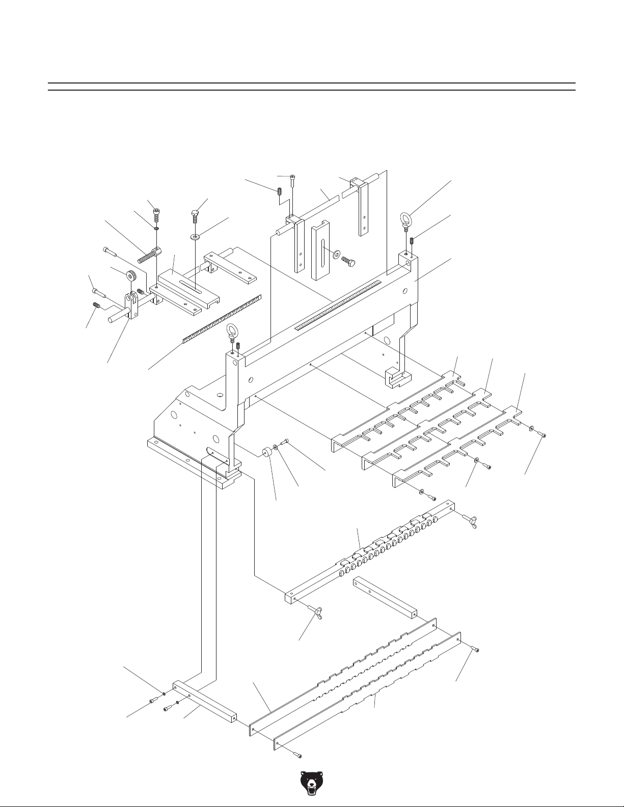
10
We do our best to stock replacement parts when possible, but we cannot guarantee that all parts shown
are available for purchase. Call (800) 523-4777 or visit www.grizzly.com/parts to check for availability.
SECTION 9: PARTS
Table
4
8
9
5
6
3
1
2
32
31
7
11
3
4
12
13
24
23
22
21
30
27
29
28
26
25
20
14
17
19
18
Model G 0611X (Mfd. 07/15)
-40-
15
16
Page 43

Table Parts List
REF PART # DESCRIPTION REF PART # DESCRIPTION
1 P0611X001 FENCE 17 P0611X017 INDICATOR TEMPLATE 1" & 2"
2 P0611X002 SLIDING ROD 18 P0611X018 INDICATOR TEMPLATE 1-1/2" & 2-1/2"
3 PSB31M CAP SCREW M8-1.25 X 25 19 PSB04M CAP SCREW M6-1 X 10
4 PSS04M SET SCREW M6-1 X 12 20 P0611X020 WING SCREW M6-1 X 35
5 PB09M HEX BOLT M8-1.25 X 20 21 P0611X021 TEMPLATE BAR
6 PW01M FLAT WASHER 8MM 22 P0611X022 BUFFER PAD
7 P0611X007 BUFFER PAD 23 PW03M FLAT WASHER 6MM
8 PSB13M CAP SCREW M8-1.25 X 30 24 PSB02M CAP SCREW M6-1 X 20
9 PLW04M LOCK WASHER 8MM 25 PW03M FLAT WASHER 6MM
10 P0611X010 ADJUSTMENT SCREW 26 PSB07M CAP SCREW M6-1 X 30
11 P0611X011 ADJUSTMENT NUT 27 P0611X027 FIXED CHASER 1" & 2"
12 P0611X012 MICRO-ADJUSTMENT SEAT 28 P0611X028 FIXED CHASER 3"
13 P0611X013 TABLE SCALE 29 P0611X029 FIXED CHASER 2-1/2"
14 PLW03M LOCK WASHER 6MM 30 P0611X030 WORKTABLE
15 PSB48M CAP SCREW M6-1 X 35 31 PSS02M SET SCREW M6-1 X 6
16 P0611X016 INDICATOR MOUNTING BAR 32 P0611X032 EYE BOLT M10-1.5 X 15
Model G 0611X (Mfd. 07/15)
-41-
Page 44

Headstock
111
112
113
114
115
117
118
119
120
121
122
116
114A
110
123
109
107
108
124
125
126
127
128
106
145
144
105
104
102 101
103
160-1
160-2
163
146
143
162
147
159
164
148
149
150
162
161
160
159
158
157
156
155
154
153
152
151
-42-
130
130-1
129
131
133
132
134
135
136
109
142
137
139
138
141
140
129-1
129-2
129-4
129-3
129-5
Model G 0611X (Mfd. 07/15)
Page 45

Headstock Parts List
REF PART # DESCRIPTION REF PART # DESCRIPTION
101 P0611X101 SPONGE COATING 131 P0611X131 CARRIAGE
102 P0611X102 HANDLE 132 P0611X132 GUIDE ROD M25 X 750L
103 PN02M HEX NUT M10-1.5 133 P0611X133 LINEAR BUSHING 16UU
104 PZERK2 GREASE FITTING M6-1 x 5 134 P0611X134 SEAL 16 X 28 X 7 X 3
105 P0611X105 CUTTER 135 PR20M INT RETAINING RING 28MM
106 PW04M FLAT WASHER 10MM 136 P0611X136 GUIDE ROD M16 X 459L
107 P0611X107 SPECIAL ADJUSTMENT BOLT 137 P0611X137 LINEAR BUSHING 25UU
108 P0611X108 SPINDLE SLIDE SEAT 138 P0611X138 SEAL 25 X 40 X 7 X 2
109 PW01M FLAT WASHER 8MM 139 PR23M INT RETAINING RING 40MM
110 PSB157M CAP SCREW M8-1.25 X 100 140 P0611X140 FLEXIBLE HOSE 2.5" X 63"
111 PSS16M SET SCREW M8-1.25 X 10 141 P0611X141 HOSE CLAMP 2-3/4"
112 P0611X112 ECCENTRIC SPINDLE 142 PSB40M CAP SCREW M8-1.25 X 35
113 P0611X113 LOCK NUT 143 P0611X143 TRACER PIN
114 P0611X114 SPINDLE BEARING HOUSING 144 PSS53M SET SCREW M5-.8 X 12
114A P0611X114A COMPLETE SPINDLE ASSY 145 P0611X145 WING SCREW M6-1 X 20
115 P0611X115 SPACER 146 P0611X146 ADJUSTMENT SCREW
116 PSS07M SET SCREW M5-.8 X 5 147 P0611X147 PLASTIC PLUG 22MM
117 P0611X117 COMPRESSION SPRING AK-6005 148 PB03M HEX BOLT M8-1.25 X 16
118 P6005 BALL BEARING 6005 149 P0611X149 SPECIAL ADJUSTMENT BOLT
119 P0611X119 FIXING NUT 150 P0611X150 CLAMP BUSHING
120 PN06M HEX NUT M5-.8 151 PSB66M CAP SCREW M8-1.25 X 65
121 PSB79M CAP SCREW M5-.8 X 35 152 P0611X152 BUSHING
122 PSB15M CAP SCREW M5-.8 X 20 153 P0611X153 GEAR SHAFT
123 P0611X123 EXTENSION SPRING 154 P0611X154 INDICATOR BAR
124 P0611X124 FLAT BELT 670 X 25 155 P0611X155 INDICATOR BRACKET
125 PB08M HEX BOLT M6-1 X 20 156 PW05M FLAT WASHER 4MM
126 PW03M FLAT WASHER 6MM 157 PSB17M CAP SCREW M4-.7 X 10
127 P0611X127 MOTOR PULLEY 158 PSB33M CAP SCREW M5-.8 X 12
128 P0611X128 MOTOR BRACKET 159 PW02M FLAT WASHER 5MM
129 P0611X129 MOTOR 1HP, 110V/220V 160 P0611X160 GUARD
129-1 P0611X129-1 MOTOR FAN COVER 160-1 P0611X160-1 TOP GUARD BRUSH
129-2 P0611X129-2 MOTOR FAN 160-2 P0611X160-2 SIDE GUARD BRUSH
129-3 P0611X129-3 MOTOR JUNCTION BOX 161 P0611X161 WINDOW
129-4 P0611X129-4 S CAPACITOR 300MFD 250VAC 162 PS17M PHLP HD SCR M4-.7 X 6
129-5 P0611X129-5 R CAPACITOR 30MFD 250VAC 163 P0611X163 CONTROL PANEL LABEL
130 P0611X130 STRAIN RELIEF 11-10B 164 P0611X164 WING SCREW M5-.8 X 15
130-1 P0611X130-1 MOTOR CORD
Model G 0611X (Mfd. 07/15)
-43-
Page 46

Body & Pneumatic
=
AIR TUBE CONNECTION POINT
234A
247
309
415
414
205
210 209
1/4
3/8
201V2
232
301
302
416
310
206
207
208
3/8
305
306
205
303
310
1/8
309
312
1/8
232
311
312
305
415
1/8
1/8
205
306
414
232
311
232
304
232
308
307
415
232
1/8
1/8
307
308
234
235
236
237
238
239
232
231
211
220V
246
245
244
243
242
241
240
230A
110V
230
229
211
212
215
216
213
214
222
223
220
226
224 225
221
227
230-1
230-2
230-3
230-4
228
230A-1
230A-2
219
-44-
217
218
Model G 0611X (Mfd. 07/15)
Page 47

Body & Pneumatic Parts List
REF PART # DESCRIPTION REF PART # DESCRIPTION
201V2 P0611X201V2 CONTROL VALVE V2.07.15 231 P0611X231 SWITCH BRACKET
205 P0611X205 T-CONNECTOR PT-1/8" X 6MM X 6MM 232 P0611X232 MALE ELBOW PT1/8" X 6MM
206 P0611X206 CAP SCREW M8-1.25 X 35 233 P0611X233 CAP SCREW M5-.8 X 50
207 P0611X207 LOCK WASHER 8MM 234 P0611X234 CYLINDER BODY
208 P0611X208 SET SCREW M8-1.25 X 10 235 P0611X235 O-RING G80
209 P0611X209 ADAPTER 3/8" X 1/4" 236 P0611X236 O-RING P25
210 P0611X210 MALE COUPLING PT-1/4" 237 P0611X237 CYLINDER END COVER
211 P0611X211 CAP SCREW M6-1 X 16 238 P0611X238 LOCKING PIECE
212 P0611X212 FLAT WASHER 6MM 239 P0611X239 CLAMPING DISC
213 P0611X213 AIR SUPPLY UNIT MACP 300-10A 240 P0611X240 HEX BOLT M8-1.25 X 16
214 P0611X214 MALE CONNECTOR PT-3/8" X 6MM 241 P0611X241 FLAT WASHER 8MM
215 P0611X215 CAP SCREW M5-.8 X 10 242 P0611X242 PISTON ROD
216 P0611X216 DUST PORT 4" 243 P0611X243 PISTON BACKING 80 X 65 X 5.5
217 P0611X217 CABINET 244 P0611X244 WEARING 80 X 75 X 6
218 P0611X218 DOOR 245 P0611X245 PISTON
219 P0611X219 DOOR LATCH 246 P0611X246 LOCK WASHER 12MM
220 P0611X220 DOOR INSET 247 P0611X247 HEX NUT M12-1.75
221 P0611X221 PHLP HD SCR M5-.8 X 6 234A P0611X234A CLAMPING CYLINDER ASSY
222 P0611X222 STUD 301 P0611X301 PU TUBE 4 X 6 X 240MM
223 P0611X223 FLAT WASHER 20MM 302 P0611X302 PU TUBE 4 X 6 X 140MM
224 P0611X224 HEX NUT M20-2.5 303 P0611X303 PU TUBE 4 X 6 X 1360MM
225 P0611X225 SPECIAL WASHER 304 P0611X304 PU TUBE 4 X 6 X 140MM
226 P0611X226 LOCKING HANDLE M10-1.5 X 35 305 P0611X305 PU TUBE 4 X 6 X 790MM
227 P0611X227 HOLDER BRACKET 306 P0611X306 PU TUBE 4 X 6 X 730MM
228 P0611X228 POWER CORD 307 P0611X307 PU TUBE 4 X 6 X 790MM
229 P0611X229 STRAIN RELIEF MGB20G-12B 308 P0611X308 PU TUBE 4 X 6 X 730MM
230 P0611X230 MAGNETIC SWITCH ASSY 220V 309 P0611X309 PU TUBE 4 X 6 X 790MM
230A P0611X230A MAGNETIC SWITCH ASSY 110V 310 P0611X310 PU TUBE 4 X 6 X 730MM
230-1 P0611X230-1 CONTACTOR 220V 311 P0611X311 PU TUBE 4 X 6 X 790MM
230-2 P0611X230-2 OVERLOAD RELAY FOR 220V 312 P0611X312 PU TUBE 4 X 6 X 730MM
230-3 P0611X230-3 MAG SWITCH COVER 414 P0611X414 CAP SCREW M5-.8 X 30
230-4 P0611X230-4 PLASTIC SCREW 415 P0611X415 AIR DIFFUSER 1/8" NPT
230A-1 P0611X230A-1 CONTACTOR 110V 416 P0611X416 MOUNTING PLATE
230A-2 P0611X230A-2 OVERLOAD RELAY FOR 110V
Model G 0611X (Mfd. 07/15)
-45-
Page 48

402
Labels
413
163 CONTROL PANEL
412
411
401
410
409
408
403
407
404
406
405
REF PART # DESCRIPTION REF PART # DESCRIPTION
163 P0611X163 CONTROL PANEL LABEL 407 PPAINT-14 "PUTTY" TOUCH-UP PAINT
401 P0611X401 TAIL SHORTER LABEL 408 PPAINT-1 "GRIZZLY GREEN" TOUCH-UP PAINT
402 PLABEL-12A READ MANUAL LABEL 409 PLABEL-36 DISCONNECT POWER LABEL
403 P0611X403 MOTOR LABEL 410 P0611X410 MACHINE ID LABEL
404 P0611X404 G0611X MODEL # LABEL 411 PLABEL-14 ELECTRICITY LABEL
405 P0611X405 EXTREME SERIES PLATE 412 P0611X412 TAIL LONGER LABEL
406 G8589 GRIZZLY LOGO PLATE 413 P0611X413 GREASE SPINDLE LABEL
Safety labels warn about machine hazards and ways to prevent injury. The owner of this machine
MUST maintain the original location and readability of the labels on the machine. If any label is
removed or becomes unreadable, REPLACE that label before using the machine again. Contact
Grizzly at (800) 523-4777 or www.grizzly.com to order new labels.
-46-
Model G 0611X (Mfd. 07/15)
Page 49

WARRANTY CARD
Name _____________________________________________________________________________
Street _____________________________________________________________________________
City _______________________ State _________________________ Zip _____________________
Phone # ____________________ Email _________________________________________________
Model # ____________________ Order # _______________________ Serial # __________________
The following information is given on a voluntary basis. It will be used for marketing purposes to help us develop
better products and services. Of course, all information is strictly confidential.
1. How did you learn about us?
____ Advertisement ____ Friend ____ Catalog
____ Card Deck ____ Website ____ Other:
2. Which of the following magazines do you subscribe to?
____ Cabinetmaker & FDM
____ Family Handyman
____ Hand Loader
____ Handy
____ Home Shop Machinist
____ Journal of Light Cont.
____ Live Steam
____ Model Airplane News
____ Old House Journal
____ Popular Mechanics
3. What is your annual household income?
____ $20,000-$29,000 ____ $30,000-$39,000 ____ $40,000-$49,000
____ $50,000-$59,000 ____ $60,000-$69,000 ____ $70,000+
CUT ALONG DOTTED LINE
4. What is your age group?
____ 20-29 ____ 30-39 ____ 40-49
____ 50-59 ____ 60-69 ____ 70+
5. How long have you been a woodworker/metalworker?
____ 0-2 Years ____ 2-8 Years ____ 8-20 Years ____20+ Years
6. How many of your machines or tools are Grizzly?
____ 0-2 ____ 3-5 ____ 6-9 ____ 10+
____ Popular Science
____ Popular Woodworking
____ Precision Shooter
____ Projects in Metal
____ RC Modeler
____ Rie
____ Shop Notes
____ Shotgun News
____ Today’s Homeowner
____ Wood
____ Wooden Boat
____ Woodshop News
____ Woodsmith
____ Woodwork
____ Woodworker West
____ Woodworker’s Journal
____ Other:
7. Do you think your machine represents a good value? _____Yes _____No
8. Would you recommend Grizzly Industrial to a friend? _____ Yes _____No
9. Would you allow us to use your name as a reference for Grizzly customers in your area?
Note: We never use names more than 3 times. _____ Yes _____No
10. Comments: _____________________________________________________________________
_________________________________________________________________________________
_________________________________________________________________________________
Page 50

FOLD ALONG DOTTED LINE
FOLD ALONG DOTTED LINE
Place
Stamp
Here
GRIZZLY INDUSTRIAL, INC.
P.O. BOX 2069
BELLINGHAM, WA 98227-2069
Send a Grizzly Catalog to a friend:
Name_______________________________
Street_______________________________
City______________State______Zip______
TAPE ALONG EDGES--PLEASE DO NOT STAPLE
Page 51

WARRANTY AND RETURNS
We shall in no event be liable for death, injuries to persons or property or for incidental, contingent, special,
WARRANTY AND RETURNS
Grizzly Industrial, Inc. warrants every product it sells for a period of 1 year to the original purchaser from
the date of purchase. This warranty does not apply to defects due directly or indirectly to misuse, abuse,
negligence, accidents, repairs or alterations or lack of maintenance. This is Grizzly’s sole written warranty
and any and all warranties that may be implied by law, including any merchantability or fitness, for any par-
ticular purpose, are hereby limited to the duration of this written warranty. We do not warrant or represent
that the merchandise complies with the provisions of any law or acts unless the manufacturer so warrants.
In no event shall Grizzly’s liability under this warranty exceed the purchase price paid for the product and
any legal actions brought against Grizzly shall be tried in the State of Washington, County of Whatcom.
or consequential damages arising from the use of our products.
To take advantage of this warranty, contact us by mail or phone and give us all the details. We will then
issue you a “Return Number,’’ which must be clearly posted on the outside as well as the inside of the
carton. We will not accept any item back without this number. Proof of purchase must accompany the
merchandise.
The manufacturers reserve the right to change specifications at any time because they constantly strive to
achieve better quality equipment. We make every effort to ensure that our products meet high quality and
durability standards and we hope you never need to use this warranty.
Please feel free to write or call us if you have any questions about the machine or the manual.
Thank you again for your business and continued support. We hope to serve you again soon.
Page 52

 Loading...