

Page 1

MODEL G0604Z
6" JOINTER w/SPIRAL
CUTTERHEAD
OWNER'S MANUAL
(For models manufactured since 02/24)
COPYRIGHT © FEBRUARY, 2024 BY GRIZZLY INDUSTRIAL, INC.
WARNING: NO PORTION OF THIS MANUAL MAY BE REPRODUCED IN ANY SHAPE
OR FORM WITHOUT THE WRITTEN APPROVAL OF GRIZZLY INDUSTRIAL, INC.
#KS23069 PRINTED IN CHINA
***Keep for Future Reference***
V1.0 2.24
Page 2

This manual provides critical safety instructions on the proper setup,
operation, maintenance, and service of this machine/tool. Save this
document, refer to it often, and use it to instruct other operators.
Failure to read, understand and follow the instructions in this manual
may result in fire or serious personal injury—including amputation,
electrocution, or death.
The owner of this machine/tool is solely responsible for its safe use.
This responsibility includes but is not limited to proper installation in
a safe environment, personnel training and usage authorization,
proper inspection and maintenance, manual availability and comprehension, application of safety devices, cutting/sanding/grinding tool
integrity, and the usage of personal protective equipment.
The manufacturer will not be held liable for injury or property damage
from negligence, improper training, machine modifications or misuse.
Some dust created by power sanding, sawing, grinding, drilling, and
other construction activities contains chemicals known to the State
of California to cause cancer, birth defects or other reproductive
harm. Some examples of these chemicals are:
• Lead from lead-based paints.
• Crystalline silica from bricks, cement and other masonry products.
• Arsenic and chromium from chemically-treated lumber.
Your risk from these exposures varies, depending on how often you
do this type of work. To reduce your exposure to these chemicals:
Work in a well ventilated area, and work with approved safety equipment, such as those dust masks that are specially designed to filter
out microscopic particles.
Page 3

Table of Contents
INTRODUCTION ............................................... 2
Contact Info
Manual Accuracy
Identification
Controls & Components
Machine Data Sheet
SECTION 1: SAFETY
Safety Instructions for Machinery
Additional Safety for Jointers
SECTION 2: POWER SUPPLY
Converting Voltage to 220V
SECTION 3: SETUP
Needed for Setup
Unpacking
Inventory
Cleanup
Site Considerations
Assembly
Dust Collection
Test Run
Recommended Adjustments
................................................... 2
........................................... 2
................................................... 3
................................. 4
...................................... 6
....................................... 8
.................. 8
....................... 10
...................... 11
......................... 13
....................................... 14
......................................... 14
.................................................... 14
...................................................... 15
........................................................ 16
...................................... 17
..................................................... 18
............................................. 22
....................................................... 23
........................ 23
SECTION 5: ACCESSORIES
SECTION 6: MAINTENANCE
Schedule
Cleaning & Protecting
Lubrication
SECTION 7: SERVICE
Troubleshooting
Checking/Adjusting Cutterhead Guard
Tensioning/Replacing V-Belt
Aligning Pulleys
Rotating/Replacing Indexable Inserts
Checking/Adjusting Table Parallelism
Setting Outfeed Table Height
Adjusting Infeed Table Stop Bolts
Calibrating Depth Scale
Setting Fence Stops
SECTION 8: WIRING
Wiring Safety Instructions
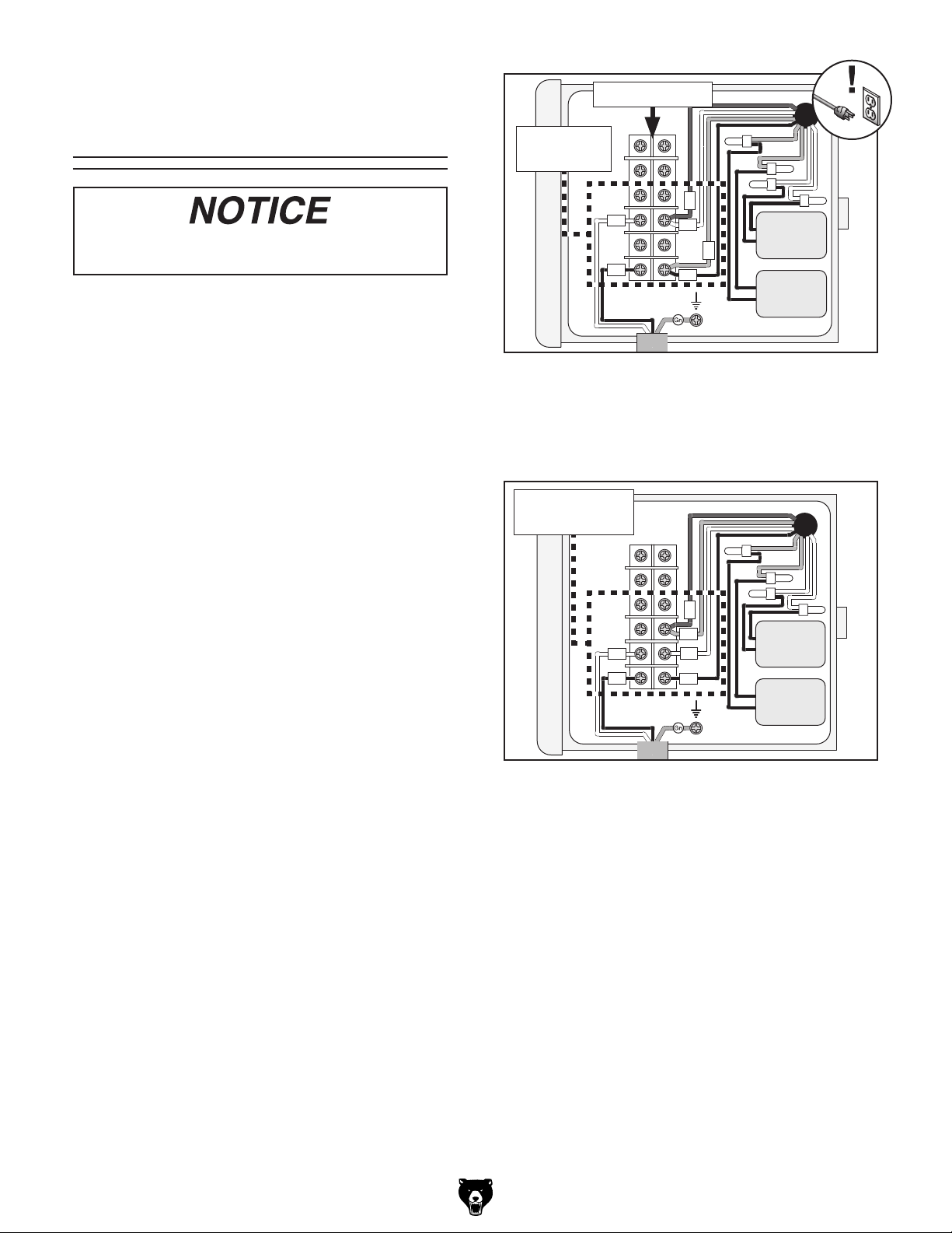
Wiring Diagram 110V
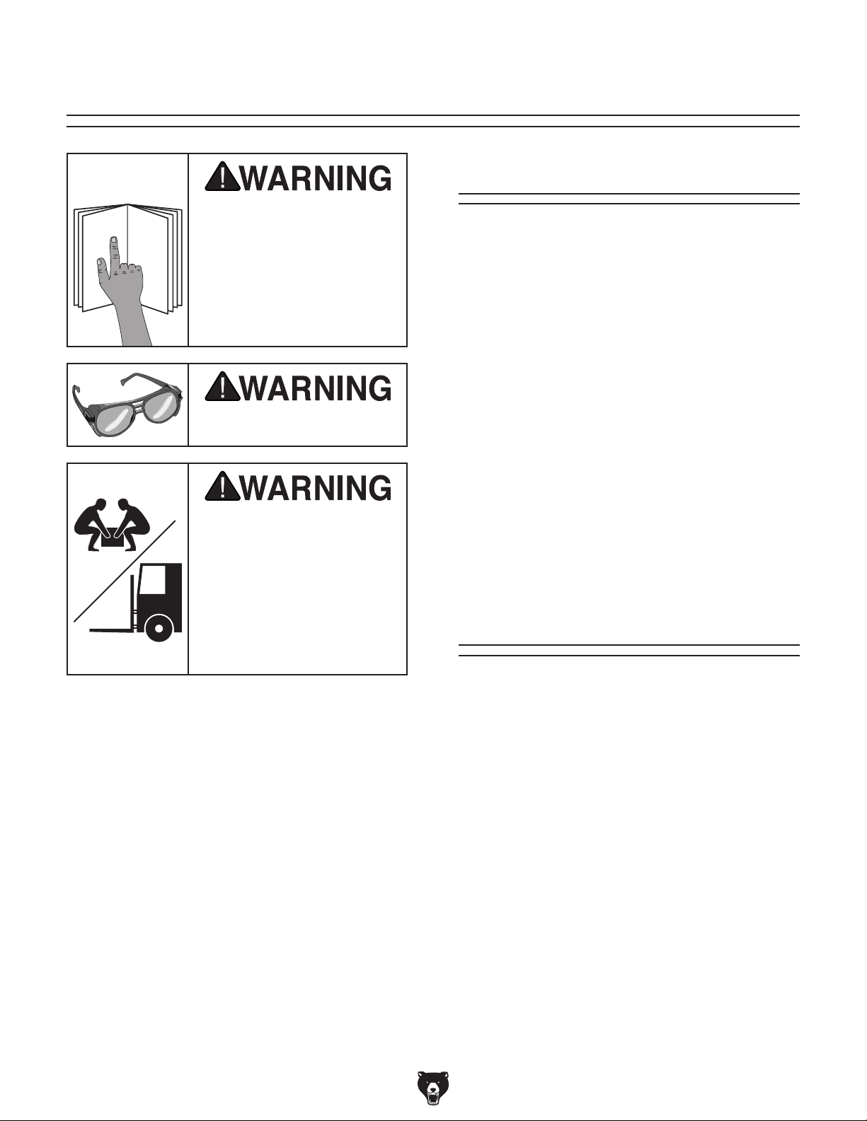
Wiring Diagram 220V
Electrical Components
...................................................... 34
................................................... 35
................................... 36
........................................... 36
........................................... 42
.................................... 50
...................................... 51
......................... 33
......................... 34
.................................. 34
........................ 41
....................... 48
............................... 49
............................ 51
................................... 52
................................... 53
................................. 54
........ 39
.......... 43
.......... 44
................ 49
SECTION 4: OPERATIONS
Operation Overview
Stock Inspection & Requirements
Setting Depth of Cut
Squaring Stock
Surface Planing
Edge Jointing
Bevel Cutting
Rabbet Cutting
............................................ 27
........................................... 28
............................................... 29
............................................... 30
............................................. 31
............................ 24
..................................... 24
.................................... 26
............... 25
SECTION 9: PARTS
............................................................. 55
Main
Cabinet
Labels & Cosmetics
WARRANTY & RETURNS
......................................................... 58
....................................... 55
..................................... 60
.............................. 61
Page 4
We stand behind our machines! If you have questions or need help, contact us with the information
below. Before contacting, make sure you get the
serial number
from the
machine ID label. This will help us help you faster.
We want your feedback on this manual. What did
you like about it? Where could it be improved?
Please take a few minutes to give us feedback.
Email: manuals@grizzly.com
We are proud to provide a high-quality owner’s
manual with your new machine!
We
instructions, specifications, drawings, and photographs
in this manual. Sometimes we make mistakes, but
our policy of continuous improvement also means
that
you receive is
slightly different than shown in the manual
If you find this to be the case, and the difference
between the manual and machine leaves you
confused or unsure about something
check our
website for an updated version. W
current
manuals and
on our web-
site at
Alternatively, you can call our Technical Support
for help. Before calling, make sure you write
down the
serial number
from the machine ID label (see below). This
information is required for us to provide proper
tech support, and it helps us determine if updated
documentation is available for your machine.
INTRODUCTION
Contact Info
and manufacture date
Grizzly Technical Support
1815 W. Battlefield
Springfield, MO 65807
Phone: (570) 546-9663
Email: techsupport@grizzly.com
Grizzly Documentation Manager
P.O. Box 2069
Bellingham, WA 98227-2069
Manual Accuracy
made every effort to be exact with the
sometimes the machine
.
,
e post
manual updates for free
www.grizzly.com.
manufacture date and
Like all machinery there is potential danger
when operating this machine. Accidents are
frequently caused by lack of familiarity or
failure to pay attention. Use this machine
with respect and caution to decrease the
risk of operator injury. If normal safety precautions are overlooked or ignored, serious
personal injury may occur.
No list of safety guidelines can be complete.
Every shop environment is different. Always
consider safety first, as it applies to your
individual working conditions. Use this and
other machinery with caution and respect.
Failure to do so could result in serious personal injury, damage to equipment, or poor
work results.
Manufacture Date
Serial Number
-2-
Model G0604Z (Mfd. Since 02/24)
Page 5
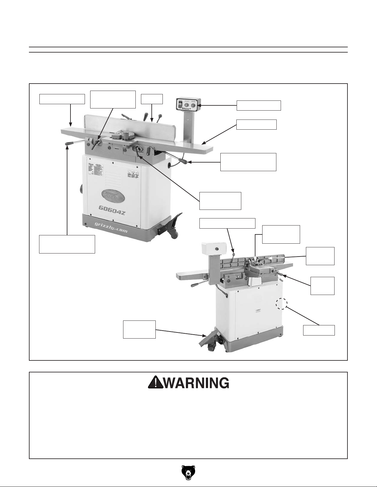
Identification
Become familiar with the names and locations of the controls and features shown below to better understand
the instructions in this manual.
Outfeed Table
Outfeed Table
Adjustment Lever
Outfeed Table
Lock
Fence
Control Panel
Infeed Table
Infeed Table
Adjustment Lever
Infeed Table
Lock
Fence Tilt Handle
Fence
Tilt Plunger
Fence
Tilt Lock
Fence
Lock
Pedal
Assembly
Dust Port
For Your Own Safety Read Instruction Manual Before Operating Jointer
a) Wear eye protection.
b) Always keep cutterhead and drive guards in place and in proper operating condition. ALWAYS
replace cutterhead guard after rabbeting operations.
c) Never make jointing or rabbeting cuts deeper than 1⁄8" or planing cuts deeper than 1⁄16".
d) Always use hold-down or push blocks when jointing material narrower than 3" or surface
planing material thinner than 3".
e) Never perform jointing, planing, or rabbeting cuts on pieces shorter than 8" in length.
Model G0604Z (Mfd. Since 02/24)
-3-
Page 6
To reduce your risk of
serious injury, read this
entire manual BEFORE
Controls &
Components
using machine.
Refer to Figures 1–4 and the following descrip-
tions to become familiar with the basic controls
and components of this machine. Understanding
these items and how they work will help you
understand the rest of the manual and stay safe
when operating this machine.
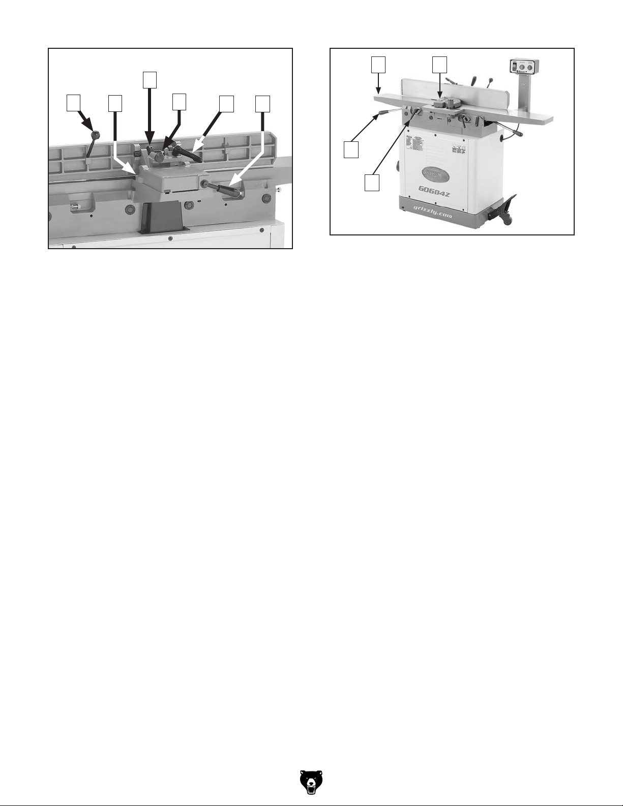
D
Figure 2. Fence, infeed table controls, and
depth-of-cut scale.
Fence: Guides workpiece as it moves across
D.
cutterhead and determines angle of cut.
Infeed Table Lock: Loosens to allow adjust-
E.
ment of infeed table height; tightens to secure
infeed table.
E
F
G
H
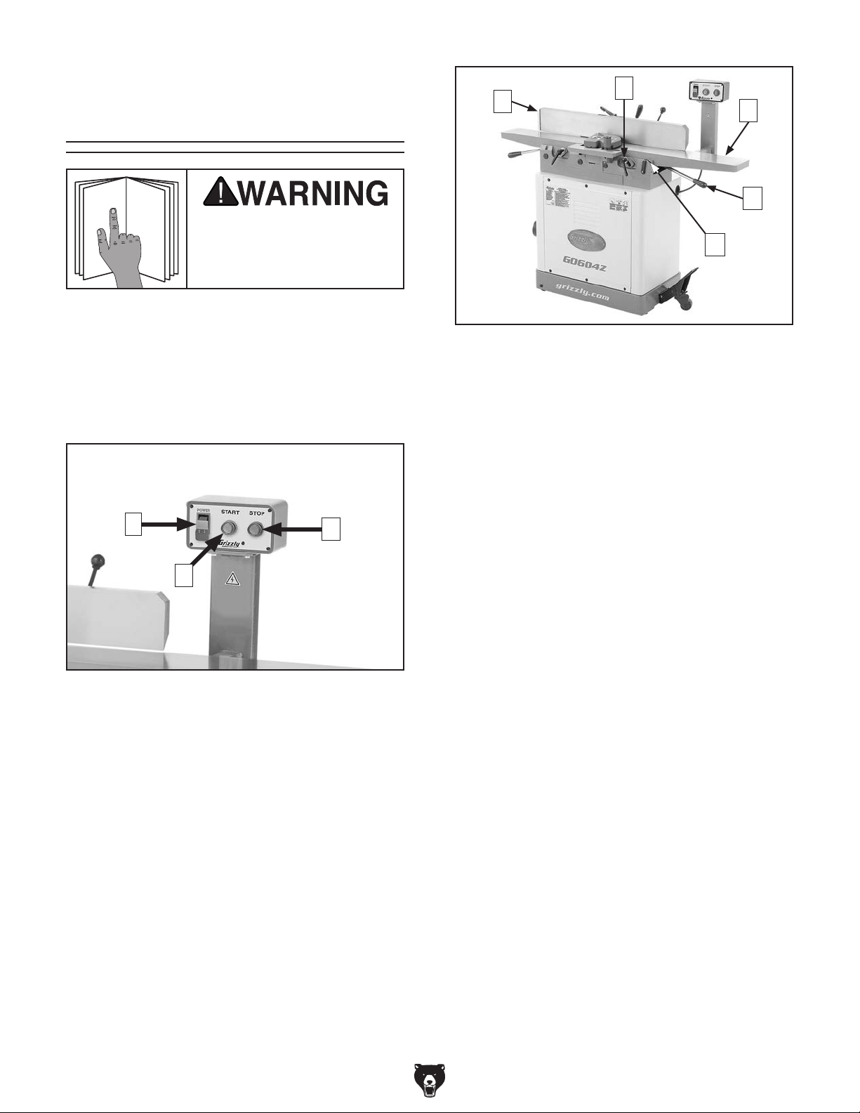
A
B
Figure 1. Power controls.
A. POWER Switch w/Disabling Key: Turns
power to machine ON or OFF. Remove
orange key to disable switch.
START Button: Turns motor ON.
B.
STOP Button: Turns motor OFF.
C.
C
Infeed Table: Supports workpiece before it
F.
reaches cutterhead. Position of infeed table
relative to cutterhead determines depth of
cut.
Infeed Table Adjustment Lever: Adjusts
G.
height of infeed table (when infeed table lock
is loosened).
Depth-of-Cut Scale: Indicates cutting depth
H.
of a single pass.
-4-
Model G0604Z (Mfd. Since 02/24)
Page 7
O
K
P
I
I. Fence Tilt Handle: Tilts fence throughout its
range of motion from 45°–135° (45° outward).
45° Fence Stop: Stops fence at 45°.
J.
90° Fence Stop: When engaged, stops
K.
fence at 90°.
135° Fence Stop: Stops fence at 135° (45°
L.
outward).
Fence Tilt Lock: Secures fence tilt setting at
M.
desired angle.
Note: Even when fence is resting against
fence stops, tilt lock must be tightened before
starting machine.
Fence Lock: Loosens to allow adjustment of
N.
fence position along width of tables; tightens
to secure fence.
J
Figure 3. Fence controls.
L
M
N
R
Q
Figure 4. Cutterhead guard and outfeed table
controls.
Outfeed Table: Supports workpiece after
O.
it passes over cutterhead. For safety and
best results, outfeed table must be properly
adjusted relative to cutterhead inserts before
ANY operations (see Page 48 for additional details).
Cutterhead Guard: Covers cutterhead
P.
until pushed out of the way by workpiece
during operation. When workpiece leaves
cutterhead, guard springs back to its starting
position.
Outfeed Table Lock: Loosens to allow
Q.
adjustment of outfeed table height; tightens
to secure outfeed table.
Outfeed Table Adjustment Lever:
R.
Adjusts height of outfeed table. Typically
only used when setting outfeed table even
with cutterhead inserts or when servicing
cutterhead.
Model G0604Z (Mfd. Since 02/24)
-5-
Page 8

MACHINE DATA
SHEET
Customer Service #: (570) 546-9663 · To Order Call: (800) 523-4777 · Fax #: (800) 438-5901
MODEL G0604Z 6" JOINTER WITH SPIRAL CUTTERHEAD
Product Dimensions:
Weight.............................................................................................................................................................. 397 lbs.
Width (side-to-side) x Depth (front-to-back) x Height..................................................................... 56 x 23-1/2 x 47 in.
Footprint (Length x Width)..................................................................................................................... 27 x 20-1/2 in.
Shipping Dimensions:
Carton #1
Type................................................................................................................................................ Wood Crate
Content................................................................................................................................................. Machine
Weight.................................................................................................................................................... 308 lbs.
Length x Width x Height............................................................................................................. 67 x 22 x 13 in.
Must Ship Upright......................................................................................................................................... Yes
Carton #2
Type................................................................................................................................................ Wood Crate
Content...................................................................................................................................................... Stand
Weight.................................................................................................................................................... 165 lbs.
Length x Width x Height............................................................................................................. 31 x 18 x 31 in.
Must Ship Upright......................................................................................................................................... Yes
Electrical:
Power Requirement............................................................................................. 110V or 220V, Single-Phase, 60 Hz
Prewired Voltage.................................................................................................................................................. 110V
Full-Load Current Rating.................................................................................................... 17A at 110V, 7.6A at 220V
Minimum Circuit Size.......................................................................................................... 20A at 110V, 15A at 220V
Connection Type....................................................................................................................................... Cord & Plug
Power Cord Included.............................................................................................................................................. Yes
Power Cord Length.............................................................................................................................................. 90 in.
Power Cord Gauge......................................................................................................................................... 14 AWG
Plug Included.......................................................................................................................................................... Yes
Included Plug Type................................................................................................................................. 5-20 for 110V
Recommended Plug Type...................................................................................................................... 6-15 for 220V
Switch Type............................................................................................ Control Panel w/Magnetic Switch Protection
-6-
Motors:
Main
Horsepower............................................................................................................................................. 1.7 HP
Phase............................................................................................................................................ Single-Phase
Amps.................................................................................................................................................... 17A/7.6A
Speed................................................................................................................................................ 3400 RPM
Type................................................................................................................. TEFC Capacitor-Start Induction
Power Transfer ............................................................................................................................................ Belt
Bearings..................................................................................................... Shielded & Permanently Lubricated
Centrifugal Switch/Contacts Type......................................................................................................... External
Model G0604Z (Mfd. Since 02/24)
Page 9

Main Specifications:
Main Specifications
Fence Information
Cutterhead Information
Cutter Insert Information
Jointer Size.................................................................................................................................................. 6 in.
Bevel Jointing............................................................................................................................. 0 - 45 deg. L/R
Maximum Width of Cut................................................................................................................................ 6 in.
Maximum Depth of Cut............................................................................................................................. 1/8 in.
Minimum Workpiece Length........................................................................................................................ 8 in.
Minimum Workpiece Thickness................................................................................................................ 1/2 in.
Maximum Rabbeting Depth...................................................................................................................... 1/2 in.
Number of Cuts Per Minute...................................................................................................................... 22668
Fence Length............................................................................................................................................. 36 in.
Fence Width.......................................................................................................................................... 1-1/4 in.
Fence Height............................................................................................................................................... 5 in.
Fence Stops............................................................................................................................. 45, 90, 135 deg.
Cutterhead Type........................................................................................................................................ Spiral
Cutterhead Diameter................................................................................................................................... 3 in.
Number of Cutter Rows.................................................................................................................................... 4
Number of Indexable Cutters.......................................................................................................................... 30
Cutterhead Speed............................................................................................................................. 5667 RPM
Cutter Insert Type.................................................................................................................. Indexable Carbide
Cutter Insert Length.................................................................................................................................. 14mm
Cutter Insert Width.................................................................................................................................... 14mm
Cutter Insert Thickness............................................................................................................................... 2mm
Table Information
Table Length........................................................................................................................................ 55-1/2 in.
Table Width.................................................................................................................................................. 6 in.
Table Thickness.................................................................................................................................... 1-1/2 in.
Floor to Table Height........................................................................................................................... 32-1/2 in.
Table Adjustment Type................................................................................................................... Lever Action
Table Movement Type.................................................................................................................. Parallelogram
Construction
Base..................................................................................................................................................... Cast Iron
Body Assembly.................................................................................................................................... Cast Iron
Cabinet.................................................................................................................................... Pre-formed Steel
Fence Assembly.................................................................................................................................. Cast Iron
Guard.................................................................................................................................................. Aluminum
Table....................................................................................................................... Precision-Ground Cast Iron
Paint Type/Finish....................................................................................................................... Powder Coated
Other Information
Number of Dust Ports....................................................................................................................................... 1
Dust Port Size.............................................................................................................................................. 4 in.
Mobile Base............................................................................................................................................. Built-In
Other Specifications:
Country of Origin ................................................................................................................................................ China
Warranty ........................................................................................................................................................... 1 Year
Approximate Assembly & Setup Time ............................................................................................................. 2 Hours
Serial Number Location .................................................................................................................................. ID Label
Certified by a Nationally Recognized Testing Laboratory (NRTL) ......................................................................... Yes
Model G0604Z (Mfd. Since 02/24)
-7-
Page 10

SECTION 1: SAFETY
For Your Own Safety, Read Instruction
Manual Before Operating This Machine
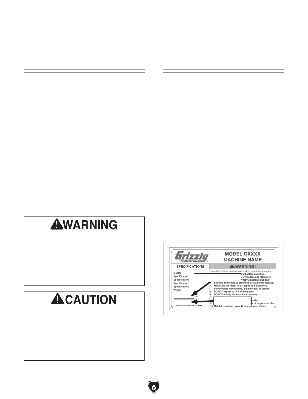
The purpose of safety symbols is to attract your attention to possible hazardous conditions.
This manual uses a series of symbols and signal words intended to convey the level of importance of the safety messages. The progression of symbols is described below. Remember that
safety messages by themselves do not eliminate danger and are not a substitute for proper
accident prevention measures. Always use common sense and good judgment.
Indicates an imminently hazardous situation which, if not avoided,
WILL result in death or serious injury.
Indicates a potentially hazardous situation which, if not avoided,
COULD result in death or serious injury.
Indicates a potentially hazardous situation which, if not avoided,
MAY result in minor or moderate injury. It may also be used to alert
against unsafe practices.
Alerts the user to useful information about proper operation of the
NOTICE
machine to avoid machine damage.
Safety Instructions for Machinery
OWNER’S MANUAL. Read and understand this
owner’s manual BEFORE using machine.
TRAINED OPERATORS ONLY. Untrained operators have a higher risk of being hurt or killed.
Only allow trained/supervised people to use this
machine. When machine is not being used, disconnect power, remove switch keys, or lock-out
machine to prevent unauthorized use—especially
around children. Make your workshop kid proof!
DANGEROUS ENVIRONMENTS. Do not use
machinery in areas that are wet, cluttered, or have
poor lighting. Operating machinery in these areas
greatly increases the risk of accidents and injury.
MENTAL ALERTNESS REQUIRED. Full mental
alertness is required for safe operation of machinery. Never operate under the influence of drugs or
alcohol, when tired, or when distracted.
ELECTRICAL EQUIPMENT INJURY RISKS.
You can be shocked, burned, or killed by touching
live electrical components or improperly grounded
machinery. To reduce this risk, only allow qualified
service personnel to do electrical installation or
repair work, and always disconnect power before
accessing or exposing electrical equipment.
DISCONNECT POWER FIRST.
nect machine from power supply BEFORE making adjustments, changing tooling, or servicing
machine. This prevents an injury risk from unintended startup or contact with live electrical components.
EYE PROTECTION. Always wear ANSI-approved
safety glasses or a face shield when operating
or observing machinery to reduce the risk of eye
injury or blindness from flying particles. Everyday
eyeglasses are NOT approved safety glasses.
Always discon-
-8-
Model G0604Z (Mfd. Since 02/24)
Page 11

may damage the wires inside. Do not handle
WEARING PROPER APPAREL. Do not wear
loose clothing, gloves, neckties, or jewelry that
can become entangled in moving parts. Always tie
back or cover long hair. Wear non-slip footwear to
reduce risk of slipping and losing control or accidentally contacting cutting tool or moving parts.
HAZARDOUS DUST. Dust created by machinery
operations may cause cancer, birth defects, or
long-term respiratory damage. Be aware of dust
hazards associated with each workpiece material. Always wear a NIOSH-approved respirator to
reduce your risk.
HEARING PROTECTION. Always wear hearing protection when operating or observing loud
machinery. Extended exposure to this noise without hearing protection can cause permanent
hearing loss.
REMOVE ADJUSTING TOOLS. Tools left on
machinery can become dangerous projectiles
upon startup. Never leave chuck keys, wrenches,
or any other tools on machine. Always verify
removal before starting!
USE CORRECT TOOL FOR THE JOB. Only use
this tool for its intended purpose—do not force
it or an attachment to do a job for which it was
not designed. Never make unapproved modifications—modifying tool or using it differently than
intended may result in malfunction or mechanical
failure that can lead to personal injury or death!
AWKWARD POSITIONS. Keep proper footing
and balance at all times when operating machine.
Do not overreach! Avoid awkward hand positions
that make workpiece control difficult or increase
the risk of accidental injury.
CHILDREN & BYSTANDERS. Keep children and
bystanders at a safe distance from the work area.
Stop using machine if they become a distraction.
GUARDS & COVERS. Guards and covers reduce
accidental contact with moving parts or flying
debris. Make sure they are properly installed,
undamaged, and working correctly BEFORE
operating machine.
FORCING MACHINERY. Do not force machine.
It will do the job safer and better at the rate for
which it was designed.
NEVER STAND ON MACHINE. Serious injury
may occur if machine is tipped or if the cutting
tool is unintentionally contacted.
STABLE MACHINE. Unexpected movement during operation greatly increases risk of injury or
loss of control. Before starting, verify machine is
stable and mobile base (if used) is locked.
USE RECOMMENDED ACCESSORIES. Consult
this owner’s manual or the manufacturer for rec-
ommended accessories. Using improper accessories will increase the risk of serious injury.
UNATTENDED OPERATION. To reduce the
risk of accidental injury, turn machine OFF and
ensure all moving parts completely stop before
walking away. Never leave machine running
while unattended.
MAINTAIN WITH CARE. Follow all maintenance
instructions and lubrication schedules to keep
machine in good working condition. A machine
that is improperly maintained could malfunction,
leading to serious personal injury or death.
DAMAGED PARTS. Regularly inspect machine
for damaged, loose, or mis-adjusted parts—or
any condition that could affect safe operation.
Immediately repair/replace BEFORE operating
machine. For your own safety, DO NOT operate
machine with damaged parts!
MAINTAIN POWER CORDS. When disconnecting cord-connected machines from power, grab
and pull the plug—NOT the cord. Pulling the cord
cord/plug with wet hands. Avoid cord damage by
keeping it away from heated surfaces, high traffic
areas, harsh chemicals, and wet/damp locations.
EXPERIENCING DIFFICULTIES. If at any time
you experience difficulties performing the intended operation, stop using the machine! Contact our
Technical Support at (570) 546-9663.
Model G0604Z (Mfd. Since 02/24)
-9-
Page 12

Kickback or
cutterhead to reach full speed before feeding.
Loose knives or
Additional Safety for Jointers
Serious cuts, amputation, entanglement, or death can occur from contact with rotating cutterhead or other moving components! Flying chips from cutting operations can cause eye injuries
or blindness. Workpieces or inserts/knives thrown by cutterhead (kickback) can strike nearby
operator or bystanders with deadly force. To reduce the risk of serious personal injury from these
hazards, operator and bystanders MUST completely heed the hazards and warnings below.
KICKBACK. Occurs when workpiece is ejected
from machine at a high rate of speed. Kickback
injuries occur from getting struck by workpiece or
hands being pulled into cutterhead. To reduce the
risk of kickback, only use proper workpieces, safe
feeding techniques, and proper machine setup or
maintenance.
GUARD REMOVAL. Operating jointer without
guards unnecessarily exposes operator to knives/
inserts and other hazardous moving parts. Except
when rabbeting, never operate jointer or allow it to
be connected to power if any guards are removed.
Turn jointer OFF and disconnect power before
clearing any shavings or sawdust from around cutterhead. After rabbeting or maintenance is complete, immediately replace all guards and ensure
they are properly installed/adjusted before resuming regular operations.
DULL OR DAMAGED KNIVES/INSERTS. Dull or
damaged knives/inserts increase risk of kickback
and cause poor workpiece finish. Only use sharp,
undamaged knives/inserts.
OUTFEED TABLE ALIGNMENT. Setting outfeed
table too high can cause workpiece to hit table or
get stuck while feeding. Setting outfeed table too
low may cause workpiece to rock or shift while
feeding. Both of these results will increase risk
of kickback. Always keep outfeed table even with
knives/inserts at highest point during rotation.
INSPECTING STOCK. Impact injuries or kickback may result from using improper workpieces.
Thoroughly inspect and prepare workpiece before
cutting. Verify workpiece is free of nails, staples,
loose knots or other foreign material. Always joint
warped workpieces with cupped side facing down.
MAXIMUM CUTTING DEPTH. To reduce risk of
kickback, never cut deeper than
1
⁄8" per pass.
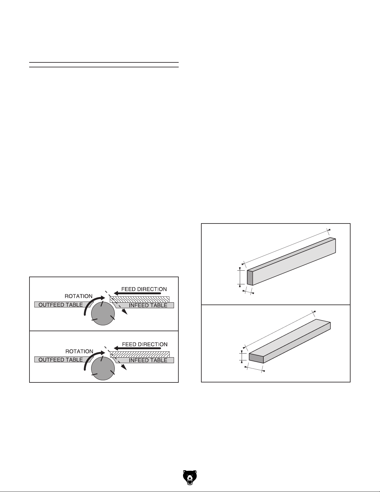
GRAIN DIRECTION. Jointing against the grain
or end grain can increase risk of kickback. It also
requires more cutting force, which produces chatter or excessive chip out. Always joint or surface
plane WITH the grain.
CUTTING LIMITATIONS. Cutting workpieces that
do not meet minimum dimension requirements can
result in kickback or accidental contact with cutterhead. Never perform jointing, planing, or rabbeting
cuts on pieces smaller than specified in machine
data sheet.
PUSH BLOCKS. Push blocks reduce risk of accidental cutterhead contact with hands. Always use
push blocks when planing materials less than 3"
high or wide. Never pass your hands directly over
cutterhead without a push block.
WORKPIECE SUPPORT. Poor workpiece support or loss of workpiece control while feeding will
increase risk of kickback or accidental contact
with cutterhead. Support workpiece with fence
continuously during operation. Support long stock
with auxiliary tables if necessary.
FEED WORKPIECE PROPERLY.
accidental cutterhead contact may result if workpiece is fed into cutterhead the wrong way. Allow
Never start jointer with workpiece touching cutterhead. Always feed workpiece from infeed side to
outfeed side without stopping until cut is complete.
Never move workpiece backwards while feeding.
SECURE KNIVES/INSERTS.
improperly set inserts can be thrown from cutterhead with dangerous force. Always verify knives/
inserts are secure and properly adjusted before
operation. Straight knives should never project
more than
1
⁄8" (0.125") from cutterhead body.
-10-
Model G0604Z (Mfd. Since 02/24)
Page 13

This machine can be converted to operate on a
power supply circuit that has a verified ground
and meets the requirements listed below. (Refer
to Voltage Conversion instructions for details.)
This machine is prewired to operate on a power
supply circuit that has a verified ground and meets
the following requirements:
Before installing the machine, consider the availability and proximity of the required power supply
circuit. If an existing circuit does not meet the
requirements for this machine, a new circuit must
be installed. To minimize the risk of electrocution,
fire, or equipment damage, installation work and
electrical wiring must be done by an electrician or
qualified service personnel in accordance with all
applicable codes and standards.
or equipment damage
may occur if machine is
not properly grounded
and connected to power
The full-load current rating is the amperage a
machine draws at 100% of the rated output power.
On machines with multiple motors, this is the
amperage drawn by the largest motor or sum of all
motors and electrical devices that might operate
at one time during normal operations.
The full-load current is not the maximum amount
of amps that the machine will draw. If the machine
is overloaded, it will draw additional amps beyond
the full-load rating.
If the machine is overloaded for a sufficient length
of time, damage, overheating, or fire may result—
especially if connected to an undersized circuit.
To reduce the risk of these hazards, avoid overloading the machine during operation and make
sure it is connected to a power supply circuit that
meets the specified circuit requirements.
For your own safety and protection of
Note: Circuit requirements in this manual apply to
a dedicated circuit—where only one machine will
be running on the circuit at a time. If machine will
be connected to a shared circuit where multiple
machines may be running at the same time, consult an electrician or qualified service personnel to
ensure circuit is properly sized for safe operation.
A power supply circuit includes all electrical
equipment between the breaker box or fuse panel
in the building and the machine. The power supply circuit used for this machine must be sized to
safely handle the full-load current drawn from the
machine for an extended period of time. (If this
machine is connected to a circuit protected by
fuses, use a time delay fuse marked D.)
SECTION 2: POWER SUPPLY
Availability
Electrocution, fire, shock,
supply.
Full-Load Current Rating
Circuit Information
property, consult an electrician if you are
unsure about wiring practices or electrical
codes in your area.
Full-Load Current Rating at 110V ..... 17 Amps
Full-Load Current Rating at 220V .... 7.6 Amps
Model G0604Z (Mfd. Since 02/24)
Circuit Requirements for 110V
Nominal Voltage .................... 110V, 115V, 120V
Cycle
Phase
Power Supply Circuit
Plug/Receptacle
..........................................................60 Hz
........................................... Single-Phase
......................... 20 Amps
............................. NEMA 5-20
Circuit Requirements for 220V
Nominal Voltage .........208V, 220V, 230V, 240V
Cycle
Phase
Power Supply Circuit
Plug/Receptacle
..........................................................60 Hz
........................................... Single-Phase
......................... 15 Amps
............................. NEMA 6-15
-11-
Page 14

For 110V operation: This machine is equipped
with a power cord that has an equipment-grounding wire and a grounding plug (see following figure). The plug must only be inserted into a matching receptacle (outlet) that is properly installed
and grounded in accordance with all local codes
and ordinances.
For 220V operation: The plug specified under
“
on the previous page has a grounding prong that must be
attached to the equipment-grounding wire on
the included power cord. The plug must only be
inserted into a matching receptacle (see following
figure) that is properly installed and grounded in
accordance with all local codes and ordinances.
Improper connection of the equipment-grounding
wire can result in a risk of electric shock. The
wire with green insulation (with or without yellow
stripes) is the equipment-grounding wire. If repair
or replacement of the power cord or plug is necessary, do not connect the equipment-grounding
wire to a live (current carrying) terminal.
Check with a qualified electrician or service personnel if you do not understand these grounding
requirements, or if you are in doubt about whether
the tool is properly grounded. If you ever notice
that a cord or plug is damaged or worn, disconnect it from power, and immediately replace it with
We do not recommend using an extension cord
with this machine. If you must use an extension
cord, only use it if absolutely necessary and only
on a temporary basis.
Extension cords cause voltage drop, which can
damage electrical components and shorten motor
life. Voltage drop increases as the extension cord
size gets longer and the gauge size gets smaller
(higher gauge numbers indicate smaller sizes).
Any extension cord used with this machine must
be in good condition and contain a ground wire
and matching plug/receptacle. Additionally, it must
meet the following size requirements:
Two-prong outlets do not meet the
grounding requirements for this machine.
provided—if it will not fit the outlet, have a
This machine MUST be grounded. In the event
of certain malfunctions or breakdowns, grounding
reduces the risk of electric shock by providing a
path of least resistance for electric current.
Grounding Requirements
GROUNDED
5-20 RECEPTACLE
Hot
Neutral
5-20 PLUG
GROUNDED
6-15 RECEPTACLE
Current Carrying Prongs
6-15 PLUG
Grounding Pin
Figure 6. Typical 6-15 plug and receptacle.
Grounding Pin
Figure 5. Typical 5-20 plug and receptacle.
SHOCK HAZARD!
Do not modify or use an adapter on the plug
qualified electrician install the proper outlet
with a verified ground.
Circuit Requirements for 220V”
-12-
Extension Cords
Minimum Gauge Size ........................... 12 AWG
Maximum Length (Shorter is Better)
Model G0604Z (Mfd. Since 02/24)
.......25 ft.
Page 15
Converting Voltage
Terminal Block
to 220V
Voltage conversion MUST be performed by
an electrician or qualified service personnel.
The voltage conversion procedure consists of
rewiring the motor and installing the correct plug.
Wiring diagrams are provided for your reference
on Pages 52–53.
IMPORTANT: If the diagram included on the
motor conflicts with the wiring diagrams in this
manual, the motor may have changed since the
manual was printed. Use the diagram provided on
the motor junction box instead.
Item(s) Needed Qty
Phillips Head Screwdriver #2 ............................ 1
6-15 Plug
Wire Cutters/Stripper
........................................................... 1
......................................... 1
Disconnect
Wires
W2
W1
U1
W1
U2
U1
Ground
S Capacitor
CD60
200μF
300VAC
R Capacitor
CBB60 40μF
450VAC
Figure 7. Inside motor junction box (motor pre-
wired to 110V).
Connect wires as shown in Figure 8, then
4.
secure terminals.
Connect Wires
and Secure
W2
To convert voltage to 220V:
1. DISCONNECT MACHINE FROM POWER!
2. Cut off existing 5-20 plug.
3. Open motor junction box and disconnect
wires from terminal block (see Figure 7).
S Capacitor
CD60
200μF
300VAC
R Capacitor
CBB60 40μF
450VAC
W1
U1
U2
W1
U1
Ground
Figure 8. Motor rewired to 220V.
Close and secure motor junction box.
5.
6. Install a 6-15 plug according to manufac-
turer's instructions. If plug manufacturer's
instructions are not available, NEMA standard 6-15 plug wiring is provided in the
Wiring Diagram 220V on Page 53.
IMPORTANT: Additional components are
required for 220V conversion. See SECTION
9: PARTS beginning on Page 55 for a
complete list of electrical components.
Model G0604Z (Mfd. Since 02/24)
-13-
Page 16
This machine was carefully packaged for safe
transport. When unpacking, separate all enclosed
items from packaging materials and inspect them
for shipping damage.
,
please
IMPORTANT: Save all packaging materials until
you are completely satisfied with the machine and
have resolved any issues between Grizzly or the
shipping agent. You MUST have the original pack-
aging to file a freight claim. It is also extremely
helpful if you need to return your machine later.
SECTION 3: SETUP
Needed for Setup
This machine presents
serious injury hazards
to untrained users. Read
through this entire manual to become familiar with
the controls and operations before starting the
machine!
Wear safety glasses during
the entire setup process!
HEAVY LIFT!
Straining or crushing injury
may occur from improperly
lifting machine or some of
its parts. To reduce this risk,
get help from other people
and use a forklift (or other
lifting equipment) rated for
weight of this machine.
The following items are needed, but not included,
for the setup/assembly of this machine.
Description Qty
• Additional Person ....................................... 1
• Safety Glasses (for each person) ............... 1
• Forklift or Hoist w/Lifting Straps
(rated for at least 400 lbs.) ......................... 1
• Phillips Head Screwdriver #2 ..................... 1
• Flat Head Screwdriver 1⁄4"........................... 1
• Straightedge (12" Minimum Length) ........... 1
• Prybar ......................................................... 1
• Power Drill w/Phillips Bit #2 ........................ 1
• Dust Collection System .............................. 1
• Dust Hose 4" .............................................. 1
• Hose Clamps 4" ......................................... 2
• Cleaner/Degreaser (Page 16) .... As Needed
• Disposable Shop Rags ............... As Needed
• Disposable Gloves ..................... As Needed
Unpacking
-14-
If items are damaged
call us immediately at (570) 546-9663.
Model G0604Z (Mfd. Since 02/24)
Page 17
The following is a list of items shipped with your
machine. Before beginning setup, lay these items
out and inventory them.
If any non-proprietary parts are missing (e.g. a
nut or a washer), we will gladly replace them; or
for the sake of expediency, replacements can be
obtained at your local hardware store.
Inventory
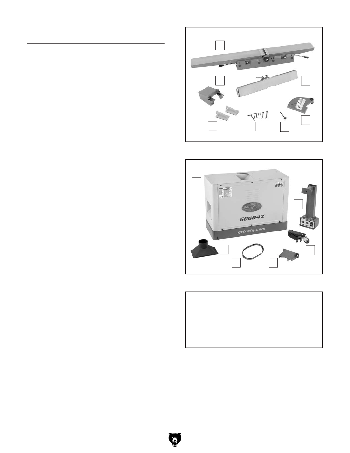
Inventory (Figures 9–10) Qty
A. Tab l e ........................................................... 1
Fence Carriage ........................................... 1
B.
Fence ......................................................... 1
C.
Cutterhead Guard ....................................... 1
D.
E. Fence Tilt Handle ....................................... 1
Loose Tools:
F.
— Wrench 8/10mm ...................................... 1
— Wrench 12/14mm .................................... 1
—Hex Wrenches 2.5, 4, 5, 6, 8mm
Push Blocks ................................................ 2
G.
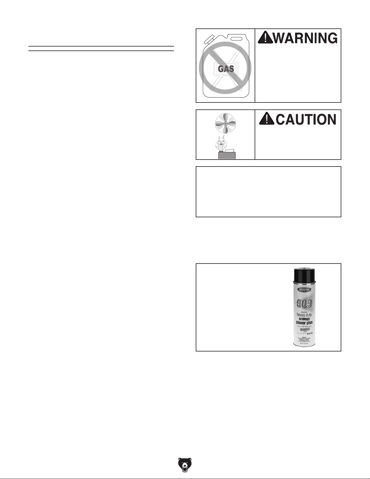
Cabinet w/Motor ......................................... 1
H.
Control Panel Pedestal (Inside Cabinet) .... 1
I.
Pedal Assembly .......................................... 1
J.
K. Belt Guard .................................................. 1
V-Belt A1120LI ............................................ 1
L.
Dust Port .................................................... 1
M.
Hardware Bag (Not Shown)
Hex Bolt M8-1.25 x 50 (Pedal/Cabinet) ...... 1
•
Flat Washer 8mm (Pedal/Cabinet) ............. 1
•
Hex Bolts M10-1.5 x 55 (Pedal/Cabinet) ..... 2
•
Flat Washers 10mm (Pedal/Cabinet) .......... 2
•
Hex Nuts M10-1.5 (Wheel/Cabinet) ............ 2
•
Cap Screws M8-1.25 x 25 (Table/Cabinet) . 4
•
Lock Washers 8mm (Table/Cabinet) .......... 4
•
Flat Washers 8mm (Table/Cabinet) ............ 4
•
Flange Bolts M6-1 x 12 (Belt Guard) .......... 2
•
Flat Washers 6mm (Belt Guard)................. 2
•
Hex Nuts M6-1 (Belt Guard) ....................... 2
•
• Driver Bits Torx T20 ................................... 2
L-Wrenches Torx T20 ................................. 2
•
Flat Hd Torx Screws T20 M6-1 x 15 ........... 3
•
Indexable Carbide Inserts 14 x 14 x 2mm .. 3
•
......1 Ea.
A
B C
D
G
Figure 9. Crate 1 inventory.
H
M
Figure 10. Crate 2 inventory.
F
E
I
J
KL
NOTICE
If you cannot find an item on this list, carefully check around/inside the machine and
packaging materials. Often, these items get
lost in packaging materials while unpacking or they are pre-installed at the factory.
Model G0604Z (Mfd. Since 02/24)
-15-
Page 18
parts of the
The unpainted surfaces of your machine are
coated with a heavy-duty rust preventative that
prevents corrosion during shipment and storage.
This rust preventative works extremely well, but it
will take a little time to clean.
Be patient and do a thorough job cleaning your
machine. The time you spend doing this now will
give you a better appreciation for the proper care
of your machine's unpainted surfaces.
There are many ways to remove this rust preventative, but the following steps work well in a wide
variety of situations. Always follow the manufac-
turer’s instructions with any cleaning product you
use and make sure you work in a well-ventilated
area to minimize exposure to toxic fumes.
Before cleaning, gather the following:
• Disposable rags
• Cleaner/degreaser (WD•40 works well)
• Safety glasses & disposable gloves
• Plastic paint scraper (optional)
Basic steps for removing rust preventative:
1.
2.
3.
4.
Many cleaning solvents
work in a well-ventilated
Cleanup
Gasoline and petroleum
products have low flash
points and can explode
or cause fire if used to
clean machinery. Avo id
using these products
to clean machinery.
Put on safety glasses.
Coat the rust preventative with a liberal
amount of cleaner/degreaser, then let it soak
for 5–10 minutes.
Wipe off the surfaces. If your cleaner/degreas-
er is effective, the rust preventative will wipe
off easily. If you have a plastic paint scraper,
scrape off as much as you can first, then wipe
off the rest with the rag.
are toxic if inhaled. Only
area.
NOTICE
Avoid harsh solvents like acetone or brake
parts cleaner that may damage painted surfaces. Always test on a small, inconspicuous location first.
T23692—Orange Power Degreaser
A great product for removing the waxy shipping grease from the non-painted
machine during clean up.
Order online at
www.grizzly.com
OR
Call 1-800-523-4777
Repeat Steps 2–3 as necessary until clean,
then coat all unpainted surfaces with a quality
metal protectant to prevent rust.
-16-
Figure 11. T23692 Orange Power Degreaser.
Model G0604Z (Mfd. Since 02/24)
Page 19

Weight Load
Refer to the
of your machine. Make sure that the surface upon
which the machine is placed will bear the weight
of the machine, additional equipment that may be
installed on the machine, and the heaviest workpiece that will be used. Additionally, consider the
weight of the operator and any dynamic loading
that may occur when operating the machine.
Space Allocation
Consider the largest size of workpiece that will
be processed through this machine and provide
enough space around the machine for adequate
operator material handling or the installation of
auxiliary equipment. With permanent installations,
leave enough space around the machine to open
or remove doors/covers as required by the maintenance and service described in this manual.
See below for required space allocation.
Physical Environment
The physical environment where the machine is
operated is important for safe operation and longevity of machine components. For best results,
operate this machine in a dry environment that is
free from excessive moisture, hazardous chemicals, airborne abrasives, or extreme conditions.
Extreme conditions for this type of machinery are
generally those where the ambient temperature
range exceeds 41°–104°F; the relative humidity
range exceeds 20%–95% (non-condensing); or
the environment is subject to vibration, shocks,
Place this machine near an existing power source.
Make sure all power cords are protected from
traffic, material handling, moisture, chemicals, or
other hazards. Make sure to leave enough space
around machine to disconnect power supply or
Lighting around the machine must be adequate
enough that operations can be performed safely.
Shadows, glare, or strobe effects that may distract
or impede the operator must be eliminated.
Site Considerations
Machine Data Sheet for the weight
or bumps.
Electrical Installation
Children or untrained people
may be seriously injured by
this machine. Only install in an
access restricted location.
Minimum 30"
apply a lockout/tagout device, if required.
Lighting
Wall
56"
23½"
= Electrical Connection
Figure 12. Minimum working clearances.
Model G0604Z (Mfd. Since 02/24)
-17-
Page 20

The machine must be fully assembled before it
can be operated. Before beginning the assembly
process, refer to
and gather
all
To ensure the assembly process
goes smoothly, first clean any
covered or coated in heavy-duty rust preventative (if
applicable).
Assembly
Needed for Setup
listed items.
parts that are
To assemble machine:
Move each crate separately to desired
1.
machine location.
Remove crate top and sides, any blocks
2.
around machine base, and any loose items
inside crate.
Remove all fasteners and shipping brackets
3.
securing machine to shipping pallet.
x 2
Figure 13. Installing pedal assembly.
Remove rear cabinet panel.
4.
5. Reach inside cabinet and remove accesso-
ries box, V-belt, and dust port.
Remove control panel pedestal and fasteners
6.
from inside cabinet and set aside.
With help from another person, place a piece
7.
of cardboard on floor, tip cabinet over so cabinet top is on cardboard, then remove plastic
from cabinet.
Attach pedal assembly to right side of cabi-
8.
net with (1) M8-1.25 x 50 hex bolt, 8mm
flat washer, and (2) M10-1.5 x 55 hex bolts,
10mm flat washers, and M10-1.5 hex nuts
(see Figure 13).
From inside cabinet, insert power cord plug
9.
through same hole in cabinet that control
panel pedestal cord is in.
With help from another person, place cabinet
10.
upright.
Attach dust port to cabinet with pre-installed
11.
Phillips head screws and flat washers, as
shown in Figure 14.
x 4
-18-
Figure 14. Installing dust port.
Model G0604Z (Mfd. Since 02/24)
Page 21

12. Remove (2) hex nuts and flat washers from
underneath shipping crate that hold table to
crate.
Wrap lifting straps around infeed and outfeed
13.
table, as illustrated in Figure 15, then attach
them to forklift or hoist.
Attach control panel pedestal to back of
16.
infeed table with (2) M8-1.25 x 25 cap
screws, 8mm lock washers, and 8mm flat
washers pre-installed on infeed table (see
Figure 17).
x 2
Figure 15. Using lifting straps to lift table.
With another person to steady load, carefully
14.
lift table over cabinet and align eight mounting holes in cabinet with holes in bottom of
table.
Note: Make sure cutterhead pulley is facing
rear of cabinet.
15. Attach table to cabinet with (4) M8-1.25 x 25
cap screws, 8mm lock washers, and 8mm flat
washers (see Figure 16).
Figure 17. Installing control panel pedestal.
Use a straightedge to check alignment of
17.
cutterhead and motor pulleys, as shown
in Figure 18.
Cutterhead
Touching
Evenly
Motor
Straightedge
Figure 18. Pulleys aligned.
Figure 16. Securing table to cabinet.
Model G0604Z (Mfd. Since 02/24)
x 8
-19-
Page 22

— If pulleys are not aligned, loosen (4) hex
nuts on carriage bolts shown in Figure
19, shift motor horizontally to align pulleys,
then secure carriage bolts.
Figure 19. Motor adjustment.
18. Use (2) pre-installed cap screws and flat
washers to install fence carriage to rear of
table, as shown in Figure 20.
19. Wrap V-belt around cutterhead and motor
pulleys (see Figure 21). Make sure ribs of
V-belt are seated in pulley grooves.
Fence Carriage
x 2
Figure 20. Fence carriage installed.
Figure 21. V-belt installed.
20. Loosen flange nuts on carriage bolts secur-
ing motor mounting brackets, let motor slide
down to place tension on V-belt, then tighten
flange nuts (see Figure 22).
Figure 22. Motor mount flange nuts and carriage
bolts.
-20-
Model G0604Z (Mfd. Since 02/24)
Page 23

Note: When properly tensioned, there is
1
approximately
⁄4" deflection of V-belt as mod-
erate pressure is applied midway between
pulleys, as illustrated in Figure 23. If necessary, apply downward pressure on motor to
attain proper V-belt tension.
Cutterhead Pulley
Approximately
1
/4" Deflection
23. Install fence tilt handle (see Figure 25).
Fence Tilt
Handle
Motor Pulley
Figure 23. Correct V-belt deflection when
properly tensioned.
Verify outfeed table height is set correctly with
21.
inserts at top dead center (TDC) (see Setting
Outfeed Table Height on Page 48) and all
inserts are securely tightened in cutterhead.
Use (2) pre-installed cap screws on fence
22.
carriage to install fence (see Figure 24).
x 2
Figure 25. Installing fence tilt handle.
24. Use (2) M6-1 x 12 flange bolts, 6mm flat
washers, and M6-1 hex nuts to install belt
guard under fence carriage (see Figure 26).
x 2
Belt Guard
Figure 26. Installing belt guard.
Figure 24. Installing fence.
Model G0604Z (Mfd. Since 02/24)
-21-
Page 24

25. Install rear cabinet panel.
26. Set fence to 90º and move it all the way back.
27. Insert cutterhead guard shaft into extension
fence, as shown in Figure 27, so shaft flat
is facing set screw, then tighten set screw
against shaft.
Figure 27. Installing cutterhead guard.
Dust Collection
DO NOT operate Model G0604Z without
an adequate dust collection system. This
jointer creates substantial amounts of wood
dust while operating. Failure to use a dust
collection system can result in short and
long-term respiratory illness.
Recommended CFM at Dust Port: 400 CFM
Do not confuse this CFM recommendation with
the rating of the dust collector. To determine the
CFM at the dust port, you must consider these
variables: (1) CFM rating of the dust collector,
(2) hose type and length between the dust collector and the machine, (3) number of branches
or wyes, and (4) amount of other open lines
throughout the system. Explaining how to calculate these variables is beyond the scope of
this manual. Consult an expert or purchase a
good dust collection "how-to" book.
The cutterhead guard is a critical safety
feature of this jointer. You MUST verify its
operation before using the jointer! Failure
to properly install this guard will greatly
increase risk of serious personal injury.
28. Verify proper operation of cutterhead guard
by setting fence to 90°, moving fence to rear
of table, then pulling cutterhead guard back
and letting it go. It should spring back over
cutterhead and contact fence without dragging across outfeed table.
If cutterhead guard DOES NOT spring
—
back over cutterhead and contact fence,
or if it drags across outfeed table, then
it must be adjusted (see Checking/
Adjusting Cutterhead Guard on Page
39 for complete instructions).
To connect a dust collection hose:
Fit 4" dust hose over dust port on left side
1.
of cabinet and secure in place with a hose
clamp (see Figure 28).
Tug hose to make sure it does not come off.
2.
Note: A tight fit is necessary for proper
performance.
-22-
Figure 28. Example of dust hose connected to
dust port.
Model G0604Z (Mfd. Since 02/24)
Page 25

Once assembly is complete, test run the machine
to ensure it is properly connected to power and
safety components are functioning correctly.
If you find an unusual problem during the test run,
immediately stop the machine, disconnect it from
power, and fix the problem BEFORE operating the
machine again. The
table in the
SERVICE section of this manual can help.
DO NOT start machine until all preceding
setup instructions have been performed.
Operating an improperly set up machine
ed results that can lead to serious injury,
Serious injury or death can result from
Test Run
Troubleshooting
6.
Move POWER switch to OFF position and
remove switch disabling key (see Figure 29).
The Test Run consists of verifying the following:
1) The motor powers up and runs correctly, and
2) the switch disabling key disables the switch
properly.
using this machine BEFORE understanding
its controls and related safety information.
DO NOT operate, or allow others to operate,
machine until the information is understood.
may result in malfunction or unexpect-
death, or machine/property damage.
Figure 29. Removing switch disabling key from
paddle switch.
7.
Try to start machine with paddle switch dis-
abling key removed. Machine should not
start.
— If machine does not start, switch disabling
feature is working correctly.
— If machine does start, immediately stop
machine. Switch disabling feature is not
working correctly. This safety feature must
work properly before proceeding with
operations. Call Tech Support for help.
Recommended
Adjustments
To test run machine:
1. Clear all setup tools away from machine.
2. Ensure POWER switch is in down position.
3. Connect machine to power supply.
4. Move POWER switch to up position to turn
machine ON.
Press START button to start motor. Verify
5.
motor operation, then press STOP button to
stop motor.
The motor should run smoothly and without
unusual problems or noises.
Model G0604Z (Mfd. Since 02/24)
For your convenience, the adjustments listed
below have been performed at the factory and no
further setup is required to operate your machine.
However, because of the many variables involved
with shipping, we recommend that you at least
verify the following adjustments to ensure the best
possible results from your new machine.
Factory adjustments that should be verified:
Table Parallelism (Page 44).
•
Calibrating Depth Scale (Page 49).
•
Setting Fence Stops (Page 50).
•
-23-
Page 26

The purpose of this overview is to provide the
novice machine operator with a basic understanding of how the machine is used during operation,
so the
discussed
later in this manual
Due to the generic nature of this overview, it is
not intended to be an instructional guide. To learn
more about specific operations, read this entire
manual,
training from experienced
machine operators, and do additional research
outside of this manual by reading "how-to" books,
trade magazines, or websites.
To reduce your risk of
serious injury, read this
entire manual BEFORE
ing loss can occur while operating this
SECTION 4: OPERATIONS
Operation Overview
machine controls/components
are easier to understand.
seek additional
To complete a typical operation, the operator
does the following:
Examines workpiece to verify it is safe and
1.
suitable for jointing.
Adjusts fence for width of workpiece and
2.
locks it in place.
Adjusts fence tilt, if necessary.
3.
Adjusts infeed table height to set depth of cut
4.
per pass.
Ensures cutterhead guard position and oper-
5.
ation are functioning properly.
Puts on safety glasses, respirator, hearing
6.
protection, and any other required protective
equipment.
using machine.
Eye injuries, respiratory problems, or hear-
tool. Wear personal protective equipment
to reduce your risk from these hazards.
If you are not experienced with this type
of machine, WE STRONGLY RECOMMEND
that you seek additional training outside of
this manual. Read books/magazines or get
formal training before beginning any projects. Regardless of the content in this section, Grizzly Industrial will not be held liable
for accidents caused by lack of training.
-24-
Starts dust collection and jointer.
7.
Using push blocks as needed, holds
8.
workpiece firmly against infeed table and
fence, and feeds workpiece into cutterhead at
a steady and controlled rate until entire length
of workpiece has been cut and it clears the
cutterhead on the outfeed table side.
Repeats cutting process described above
9.
until desired results are achieved.
Stops jointer and dust collection.
10.
Model G0604Z (Mfd. Since 02/24)
Page 27
• Scrape all glue off the workpiece before
Glue deposits on the workpiece,
hard or soft, will gum up the cutterhead and
• Remove foreign objects from the work-
Make sure that any stock you process with the jointer is clean and free of dirt,
nails, staples, tiny rocks or any other foreign
objects that could damage the cutterhead.
These particles could also cause a spark as
they strike the cutterhead and create a fire
Wood stacked on a concrete
or dirt surface can have small pieces of con-
• Make sure all stock is sufficiently dried
Wood with a moisture content over 20% will cause unnecessary wear
on the cutters and poor cutting results. Excess
moisture can also hasten rust and corrosion.
Follow these rules when choosing and jointing
stock:
• DO NOT joint or surface plane stock that
Injury to the
operator or damage to the workpiece can
occur if a knot becomes dislodged during the
• DO NOT joint or surface plane against the
Cutting against the grain
increases the likelihood of kickback, as well
• Jointing and surface planing with the
grain produces a better finish and is safer
Cutting with the grain is
described as feeding the stock on the jointer so
the grain points down and toward you as viewed
If the grain changes direction along the
edge of the board, decrease the cutting depth
and make additional passes.
• Only cut natural wood. This jointer is only
designed for cutting natural wood stock.
wood, laminates, drywall, backer board, metals,
glass, stone, tile, products with lead-based
paint, or products that contain asbestos. Cutting
these may lead to injury or machine damage.
Stock Inspection &
jointing.
Requirements
contains large or loose knots.
cutting operation.
grain direction.
as tear-out on the workpiece.
for the operator.
on the edge of the stock (see Figure below).
produce poor results.
piece.
hazard.
IMPORTANT:
crete or stone pressed into the surface.
before jointing.
Edge Jointing
Note:
CORRECT
INCORRECT
Figure 30. Proper grain alignment with
Never use it to cut MDF, particle board, ply-
Model G0604Z (Mfd. Since 02/24)
cutterhead.
With Grain
Against Grain
8" Min.
3
/4" Min.
1
/4" Min.
Surface Planing
8" Min.
1
/2" Min.
3
/4" Min.
Figure 31. Minimum stock dimensions for jointer.
-25-
Page 28

Setting Depth of Cut
The depth of cut on a jointer is the amount of material removed from the bottom of the workpiece as
it passes over the cutterhead.
The depth of cut is set by adjusting the height of
the infeed table relative to the carbide inserts at
TDC (top dead center).
Depth-of-Cut Scale
The depth of cut can be referenced directly from
the depth scale located on the front of the jointer
(see figures below).
Note: The depth scale can be calibrated or
"zeroed" if it is not correct. Refer to Calibrating
Depth Scale on Page 49 for more information.
DO NOT exceed 1⁄8" depth of cut per pass
when edge jointing and
pass when surface planing on this machine
or kickback and serious injury may occur!
1
⁄16" depth of cut per
Adjusting Infeed Table Height
To adjust the infeed table height, loosen the
infeed table lock, use the infeed table adjustment
lever to raise or lower the table, then tighten the
lock to secure the setting (see Figure 32).
Infeed Table Lock
Figure 33. Location of depth-of-cut scale.
Depth Scale
Pointer
Scale
-26-
Infeed
Table
Adjustment
Lever
Figure 32. Infeed table controls.
Figure 34. Location of depth-of-cut components.
Model G0604Z (Mfd. Since 02/24)
Page 29
Squaring stock involves four steps performed
in the order below:
1. Surface Plane on Jointer—Concave face of
workpiece is surface planed flat with jointer.
2. Surface Plane on a Thickness Planer—
Opposite face of workpiece is surface planed
flat with a thickness planer.
3. Edge Joint on Jointer—Concave edge of
workpiece is jointed flat with jointer.
4. Rip Cut on a Table Saw—Jointed edge
of workpiece is placed against a table saw
fence and opposite edge cut off.
Squaring Stock
Previously
Jointed
45
30
15
Edge
Previously Surface
Planed Face
Model G0604Z (Mfd. Since 02/24)
-27-
Page 30

To surface plane on jointer:
1.
Stock Inspection &
2. Set infeed table height to desired cutting
To minimize risk of kickback,
" per pass
3.
4.
5. Place workpiece firmly against fence and
To ensure workpiece remains
of workpiece
6.
head while keeping it firmly against fence
Keep hands at least 4" away
from cutterhead during the entire cut. Instead
of allowing a hand to pass directly over cutterhead, lift it up and over cutterhead, and
safely reposition it on the outfeed side to continue supporting workpiece. Use push blocks
whenever practical to further reduce risk of
7.
When squaring up stock, cut opposite
side of workpiece with a planer instead of the
jointer to ensure both sides are parallel.
Failure to use push blocks when surface
ing rotating cutterhead, which will cause
serious personal injury. ALWAYS use push
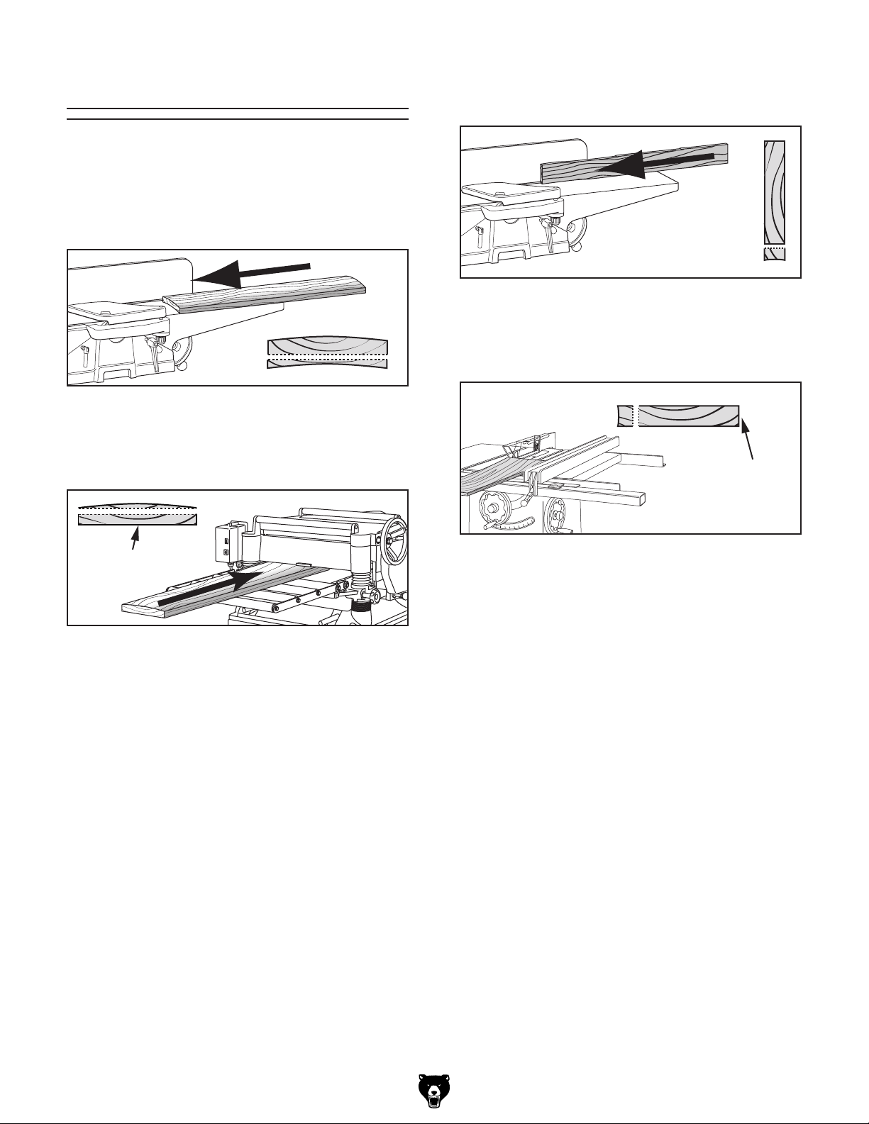
The purpose of surface planing (see example
Figures
on the jointer is to make one flat
face on a piece of stock to prepare it for thickness
planing on a planer.
Surface Planing
below)
planing could result in your hands contact-
Inspect stock to ensure it is safe and suitable
for the operation (see
Requirements section).
depth for each pass.
CAUTION:
do not exceed a cutting depth of
when surface planing.
Set fence to 90°.
1
⁄16
blocks when surface planing on jointer!
Figure 35. Example of surface planing operation.
Start jointer.
infeed table.
CAUTION:
stable during cut, concave sides
must face toward table and fence.
Feed workpiece completely across cutter-
and tables during the entire cut.
CAUTION:
accidental hand contact with cutterhead.
Repeat Step 6 until entire surface is flat.
Figure 36. Illustration of surface planing results.
-28-
Removed
Surface
Tip:
Model G0604Z (Mfd. Since 02/24)
Page 31
To edge joint on jointer:
1.
Stock Inspection &
2.
Surface
3. Set infeed table height to desired cutting
To minimize risk of kickback,
.
4.
5.
6. Place workpiece firmly against fence and
To ensure workpiece remains
of workpiece
7.
head while keeping it firmly against fence
Keep hands at least 4" away
from cutterhead during the entire cut. Instead
of allowing a hand to pass directly over cutterhead, lift it up and over cutterhead, and
safely reposition it on the outfeed side to continue supporting workpiece. Use push blocks
whenever practical to further reduce risk of
8.
When squaring up stock, cut opposite
edge of workpiece with a table saw instead
of the jointer—otherwise, both edges of workpiece will not be parallel with each other.
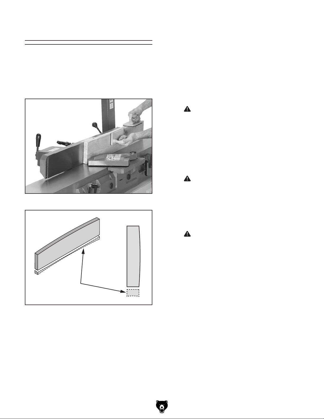
Edge jointing (see example Figures below) produces a flat and true surface along the side of
a workpiece by removing uneven areas.
an
essential step for
or rough
stock and when preparing a workpiece for joinery
or finishing.
Edge Jointing
Inspect stock to ensure it is safe and suitable
for the operation (see
Requirements section).
squaring up warped
Figure 37. Example of edge jointing operation.
It is
Surface plane workpiece (see
Planing section).
depth for each pass.
CAUTION:
do not exceed a cutting depth of
Set fence to 90°.
Start jointer.
infeed table with concave side facing down.
CAUTION:
stable during cut, concave sides
must face toward table and fence.
Feed workpiece completely across cutter-
and tables during the entire cut.
CAUTION:
1
⁄8" per pass
Figure 38. Illustration of edge jointing results.
Model G0604Z (Mfd. Since 02/24)
Removed
Surface
accidental hand contact with cutterhead.
Repeat Step 6 until the entire edge is flat.
Tip:
-29-
Page 32

To bevel cut on jointer:
1.
Stock Inspection &
2.
Surface
3.
g
4. Set infeed table height to cutting depth
Cutting depth for bevel cuts is
, depending on
5.
6.
7.
8.
workpiece against table and fence with firm
pressure, and feed workpiece over cutter-
When your leading hand gets
within 4" of the cutterhead, lift it up and over
cutterhead, and place push block on portion
.
Now, focus your pressure on outfeed end
of the workpiece while feeding, and repeat
same action with your trailing hand when it
keep
your hands safe, DO NOT let them get closer
at any time
9.
you are satisfied with the results.
Bevel cuts (see example Figures below) can be
made by setting the fence at the desired angle
and feeding the workpiece firmly along the fence
face, with the bottom inside corner firmly against
the table. The cutting process typically requires
multiple passes or cuts to bevel the entire edge
of a workpiece.
Bevel Cutting
Inspect stock to ensure it is safe and suitable
for the operation (see
Requirements section).
Surface plane workpiece (see
Planing section).
Edge joint workpiece (see Edge Jointin
section).
Figure 39. Fence setup for a bevel cut of 45°.
desired for each pass.
CAUTION:
typically between
hardness and width of stock.
Set fence tilt to desired angle of cut.
Place workpiece against fence and infeed
table with concave side face down.
Start jointer.
With a push block in your leading hand, press
head with a push block in your trailing hand.
CAUTION:
of the workpiece once it is 4" past cutterhead
1
⁄16" and 1⁄8"
Figure 40. Illustration of bevel cutting results.
-30-
Removed
Surface
gets within 4" of cutterhead. To help
than 4" from moving cutterhead
during operation!
Repeat cutting process, as necessary, until
Model G0604Z (Mfd. Since 02/24)
Page 33

A rabbet cut removes a portion of a workpiece
edge, so it fits together with an opposing, equally
sized rabbet cut on another workpiece (see example
. This is a classic method of
joining two workpieces that is simple, yet strong.
This jointer can be used to make high-quality rabbet cuts, but there are some situations—whether
it
s due to an excessively large/small workpiece
size or rabbet cutting width/depth—when it will not
be safe or appropriate for making the rabbet cut
on this jointer. In these cases, you need to use
another tool or method for rabbet cutting that will
be a safer alternative.
A
alternatively be made using a
table saw, router, or even a hand saw. As with any
type of cutting operation, always consider your
safety first and use good
Typically, rabbet cutting with a jointer requires
the cutterhead guard to be removed first, so the
workpiece can slide along the rabbeting ledge
during the cut. However, it is possible to make
rabbet cuts with workpieces up to 1
without
removing the cutterhead guard. This is done by
performing the rabbet cut with the workpiece on
end (similar to when you are edge jointing).
Rabbet Cutting
To rabbet cut on jointer:
Inspect stock to ensure it is safe and suitable
1.
for the operation (see Stock Inspection &
Requirements on Page 25).
Figure below)
Removed
Surface
i
Rabbet Joints
2. Set infeed table height to desired cutting
depth for each pass.
CAUTION: For safety reasons, cutting
depth should never exceed
Remove cutterhead guard if necessary to per-
3.
form operation (see Figure 41).
Guard Installed
1
⁄8" per pass.
rabbet cut can
Model G0604Z (Mfd. Since 02/24)
judgement!
" thick
Guard Removed
Figure 41. Examples of typical rabbet cutting
operations.
-31-
Page 34

When cutterhead guard is removed,
essary exposure to cutterhead, always
Feed workpiece completely across cutterhead
7.
while keeping it firmly against fence and
tables during entire cut.
attempting any other cut besides a rabbet
directly exposes operator to moving cutterhead. To minimize risk of injury and unnec-
keep cutterhead guard installed when possible, and ALWAYS immediately replace it
after performing rabbet cuts.
4. Set fence to 90° and near front of jointer,
so amount of exposed cutterhead in front of
fence matches size of desired rabbet.
Start jointer.
5.
6. Place workpiece firmly against fence and
infeed table.
CAUTION: To ensure workpiece remains
stable during cut, concave sides of workpiece
must face toward table and fence.
CAUTION: Keep hands at least 4" away
from cutterhead during the entire cut. Instead
of allowing a hand to pass directly over
cutterhead, lift it up and over cutterhead, and
safely reposition it on the outfeed side to continue supporting workpiece. Use push blocks
whenever practical to further reduce risk of
accidental hand contact with cutterhead.
Repeat Step 7 until rabbet is cut to depth.
8.
Re-install cutterhead guard if removed in
9.
Step 3 (see Checking/Adjusting Cutterhead
Guard on Page 39).
-32-
Model G0604Z (Mfd. Since 02/24)
Page 35

order online at www.grizzly.com or call 1-800-523-4777
Installing unapproved accessories may
SECTION 5: ACCESSORIES
cause machine to malfunction, resulting in
serious personal injury or machine damage.
To reduce this risk, only install accessories
recommended for this machine by Grizzly.
NOTICE
Refer to our website or latest catalog for
additional recommended accessories.
G0862—3 HP Portable Cyclone Dust Collector
The capstone of our line of affordable, high-quality cyclones, the G0862 features a 3 HP motor,
a whopping 1941 CFM of airflow capacity, and a
45-gallon collection capacity. It's packed with features like a quick-release collection drum, latching system, high-efficiency, two-stage separation
driven by a 16" aluminum impeller, durable powder coated finish, and a heavy-duty steel frame
and housing.
H7319—Indexable Carbide Inserts (10-Pack)
These indexable carbide inserts can be rotated to
provide four factory sharp edges before replacement. Inserts measure 14 x 14 x 2mm.
Figure 43. Replacement carbide inserts for
Model G0604Z.
T2 15 78—12 " Beveled Straight Edges w/Scale
T21579—24" Beveled Straight Edges w/Scale
T21580—36" Beveled Straight Edges w/Scale
These bevel straight edges are made from hardened steel and feature a satin chrome finish and
are ground and lapped for straightness and parallelism. Each straightedge offers true right angles
for all edges, along with a beveled edge with scale
in US standard.
1
⁄64" graduations.
Figure 42. Model G0862 3 HP Portable Cyclone
Dust Collector.
Model G0604Z (Mfd. Since 02/24)
Figure 44. T21578, T21579, and T21580
straightedges.
-33-
Page 36

To reduce risk of shock or
accidental startup, always
disconnect machine from
The cleaning process for this machine is simple.
Vacuum excess wood chips and sawdust, and
wipe off the remaining dust with a dry cloth. If any
resin has built up, use a resin dissolving cleaner
to remove it. Treat all unpainted cast iron and steel
with a non-staining lubricant after cleaning.
SECTION 6: MAINTENANCE
Cleaning &
Protecting
power before adjustments,
maintenance, or service.
Schedule
For optimum performance from this machine, this
maintenance schedule must be strictly followed.
Ongoing
To minimize your risk of injury and maintain proper
machine operation, shut down the machine immediately if you ever observe any of the items below,
and fix the problem before continuing operations:
• Loose mounting bolts.
• Dust or debris on and around machine.
Dull or damaged cutterhead inserts.
•
Unprotected cast-iron surfaces.
•
Worn or damaged wires.
•
Any other unsafe condition.
•
Monthly Check
• V-belt tension, damage, or wear (Page 41).
• Clean/vacuum dust buildup from inside cabi-
net and off motor.
Protect the unpainted cast iron surfaces on the
table by wiping the table clean after every use—
this ensures moisture from wood dust does not
remain on bare metal surfaces.
Keep tables rust-free with regular applications of
quality lubricants.
Recommended Metal Protectants
G5562—SLIPIT® 1 Qt. Gel
G5563—SLIPIT
®
11 Oz . Spray
-34-
Figure 45. Recommended products for
protecting unpainted cast-iron and steel.
Model G0604Z (Mfd. Since 02/24)
Page 37

Since all bearings are sealed and permanently
lubricated, simply leave them alone until they
need to be replaced. DO NOT lubricate them.
It is essential to clean components before lubricating them because dust and chips build up on
lubricated components and make them hard to
move. Simply adding more grease to them will not
yield smooth moving components.
Clean the components below with mineral spirits
or other oil/grease solvent cleaner and shop rags.
Lubrication
SB1365—South Bend Way Oil-ISO 68
Infeed/Outfeed Table Controls
Oil Type ................ SB1365 or ISO 68 Equivalent
Oil Amount
Frequency.......................................... As Needed
Lubricate the infeed/outfeed table adjustment
lever components with light machine oil as needed (see Figure 47). Wipe off excess oil and sawdust with a cloth.
............................................Thin Coat
Figure 46. Recommended product for machine
lubrication.
Figure 47. Adjustment lever lubrication location.
Fence
Oil Type ................ SB1365 or ISO 68 Equivalent
Oil Amount
Lubrication Frequency
Place one or two drops of light machine oil on
fence pivot points (see Figure 48) as needed.
...........................................1–2 Drops
....................... As Needed
Figure 48. Fence lubrication locations.
Model G0604Z (Mfd. Since 02/24)
-35-
Page 38

Review the troubleshooting procedures in this section if a problem develops with your machine. If you need
replacement parts or additional help with a procedure, call our Technical Support.
the
serial number and manufacture date of your machine before calling.
SECTION 7: SERVICE
Troubleshooting
Motor & Electrical
Symptom Possible Cause Possible Solution
Machine does
not start, or
power supply
breaker
immediately
trips after
startup.
Machine
stalls or is
underpowered.
1. POWER switch in OFF position.
2. POWER switch disabling key removed.
3. Incorrect power supply voltage or circuit size.
4. Plug/receptacle at fault/wired incorrectly.
5. Power supply circuit breaker tripped or fuse
blown.
6. Motor wires connected incorrectly.
7. Thermal overload relay has tripped/at fault.
8. Start capacitor at fault.
9. Centrifugal switch adjustment/contact points
at fault.
10. Contactor not energized/at fault.
11. Wiring broken, disconnected, or corroded.
12. ON/OFF button(s) at fault.
13. Motor or motor bearings at fault.
1. Workpiece material unsuitable for machine.
2. Feed rate/cutting speed too fast.
3. Machine undersized for task.
4. Belt slipping/pulleys misaligned.
5. Motor wires connected incorrectly.
6. Plug/receptacle at fault/wired incorrectly.
7. Pulley slipping on shaft.
8. Motor overheated.
9. Run capacitor at fault.
10. Extension cord too long.
11. Contactor not energized/at fault.
12. Centrifugal switch/contact points at fault.
13. Motor or motor bearings at fault.
1. Move POWER switch to ON position.
2. Install POWER switch disabling key.
3. Ensure correct power supply voltage and circuit size.
4. Test for good contacts; correct wiring.
5. Ensure circuit is free of shorts. Reset circuit breaker or
replace fuse.
6. Correct motor wiring connections (Page 51).
7. Reset. Adjust or replace if at fault.
8. Test/replace if at fault.
9. Adjust centrifugal switch/clean contact points. Replace
either if at fault.
10. Test all legs for power; replace if necessary.
11. Fix broken wires or disconnected/corroded
connections.
12. Replace button(s).
13. Replace motor.
1. Only cut wood/ensure moisture is below 20%
(Page 25).
2. Decrease feed rate/cutting speed.
3. Use sharp inserts; reduce feed rate/depth of cut
(Page 26).
4. Clean/tension/replace belt (Page 41); ensure pulleys
are aligned (Page 42).
5. Correct motor wiring connections (Page 51).
6. Test for good contacts; correct wiring.
7. Tighten/replace loose pulley/shaft.
8. Clean motor, let cool, and reduce workload.
9. Test/repair/replace.
10. Move machine closer to power supply; use shorter
extension cord (Page 12).
11. Test all legs for power; repair/replace if at fault.
12. Adjust centrifugal switch/clean contact points. Replace
either if at fault.
13. Replace motor.
Note: Please gather
-36-
Model G0604Z (Mfd. Since 02/24)
Page 39

Motor & Electrical (Cont.)
Symptom Possible Cause Possible Solution
Machine has
vibration or
noisy operation.
1. Motor or component loose.
2. Mobile cabinet feet not adjusted properly.
3. V-belt worn, loose, pulleys misaligned or belt
slapping cover.
4. Insert(s) at fault.
5. Pulley loose.
6. Motor mount loose/broken.
7. Cutterhead bearings at fault.
8. Motor fan rubbing on fan cover.
9. Centrifugal switch needs adjustment/at fault.
10. Motor bearings at fault.
1. Replace damaged or missing bolts/nuts; tighten if
loose.
2. Adjust mobile cabinet feet to stabilize machine.
3. Inspect/replace belt (Page 41). Re-align pulleys if
necessary (Page 42).
4. Rotate/replace insert(s) (Page 43).
5. Secure pulley on shaft (Page 42).
6. Tighten/replace.
7. Replace bearing(s)/re-align cutterhead.
8. Fix/replace fan cover; replace loose/damaged fan.
9. Adjust/replace if at fault.
10. Test by rotating shaft; rotational grinding/loose shaft
requires bearing replacement.
Operation
Symptom Possible Cause
Table(s) hard to
adjust.
Excessive
snipe (gouge
in end of board
that is uneven
with rest of
cut); back of
workpiece is
concave.
Workpiece
stops in middle
of cut; front of
workpiece is
concave.
Workpiece
chipping,
tear-out,
indentations, or
overall rough
cuts.
Fuzzy grain left
in workpiece.
Long lines or
ridges that run
along length of
workpiece.
1. Table lock(s) engaged/partially engaged.
2. Table stop(s) blocking movement.
1. Outfeed table set too low.
2. Operator pushing down on trailing end
(infeed side) of workpiece as it leaves
cutterhead.
1. Outfeed table set too high. 1. Align outfeed table with cutterhead inserts at top dead
1. Workpiece is rough or has loose knots/
surface aws; not suitable for jointing.
2. Not feeding workpiece to cut "with" the grain.
3. Dull inserts.
4. Nicked or chipped insert(s).
5. Feeding workpiece too fast.
6. Excessive depth of cut.
7. Lack of proper dust collection or clogged
dust port.
1. Wood has high moisture content.
2. Dull inserts.
1. Nicked or chipped inserts.
2. Loose or incorrectly installed insert(s).
3. Dirt or debris under insert(s).
Possible Solution
1. Completely loosen table lock(s) (Page 4).
2. Loosen/reset table stop(s) (Page 49).
1. Align outfeed table with cutterhead inserts at top dead
center (Page 48).
2. Focus most of the workpiece pressure against outfeed
table while cutting.
center (Page 48).
1. Inspect workpiece. Use smooth stock without loose
knots/surface aws (Page 25).
2. Flip workpiece 180° before feeding again.
3. Rotate/replace inserts (Page 43).
4. Rotate/replace inserts (Page 43).
5. Reduce feed rate.
6. Reduce depth of cut (Page 26).
7. Clear blockages, ensure dust collection is operating
efciently; upgrade dust collector.
1. Ensure wood moisture content is less than 20%. Allow
to dry if necessary (Page 25).
2. Rotate/replace inserts (Page 43).
1. Rotate/replace inserts (Page 43).
2. Remove/replace insert(s) and install properly
(Page 43).
3. Remove insert(s), clean bottom of insert/cutterhead
mounting pocket and re-install (Page 43).
Model G0604Z (Mfd. Since 02/24)
-37-
Page 40

Operation (Cont.)
Symptom Possible Cause Possible Solution
Uneven cutter
marks, wavy
surface, or
chatter marks
across face of
workpiece.
Glossy surface;
scorching or
burn marks on
workpiece.
Workpiece is
concave or
convex along
its length after
jointing.
Workpiece
edges not
square; tapered
cut produced.
1. Feeding workpiece too fast.
2. Insert(s) not properly adjusted or dirt or
debris under insert(s).
1. Dull inserts.
2. Feed rate too slow.
1. Workpiece not held with even pressure
against outfeed table during cut.
2. Workpiece too uneven at start of operation.
3. Tables not parallel with cutterhead and each
other.
1. Fence not square to table(s); fence tilt
unlocked.
2. Insert(s) not adjusted at even heights in
cutterhead.
3. Warped infeed or outfeed table.
1. Reduce feed rate.
2. Remove, clean bottom of insert/cutterhead mounting
pocket, and re-install any inserts that are "raised" in
cutterhead (Page 43).
1. Rotate/replace inserts (Page 43).
2. Increase feed rate.
1. Apply even, downward pressure against workpiece
throughout entire travel along outfeed side during cut.
2. Take partial cuts to remove extreme high spots before
doing a full pass.
3. Verify/adjust table parallelism (Page 44).
1. Square fence to table(s) (Page 50); lock fence.
2. Remove, clean bottom of insert/cutterhead mounting
pocket, and re-install any inserts that are "raised" in
cutterhead (Page 43).
3. Regrind/replace table.
-38-
Model G0604Z (Mfd. Since 02/24)
Page 41
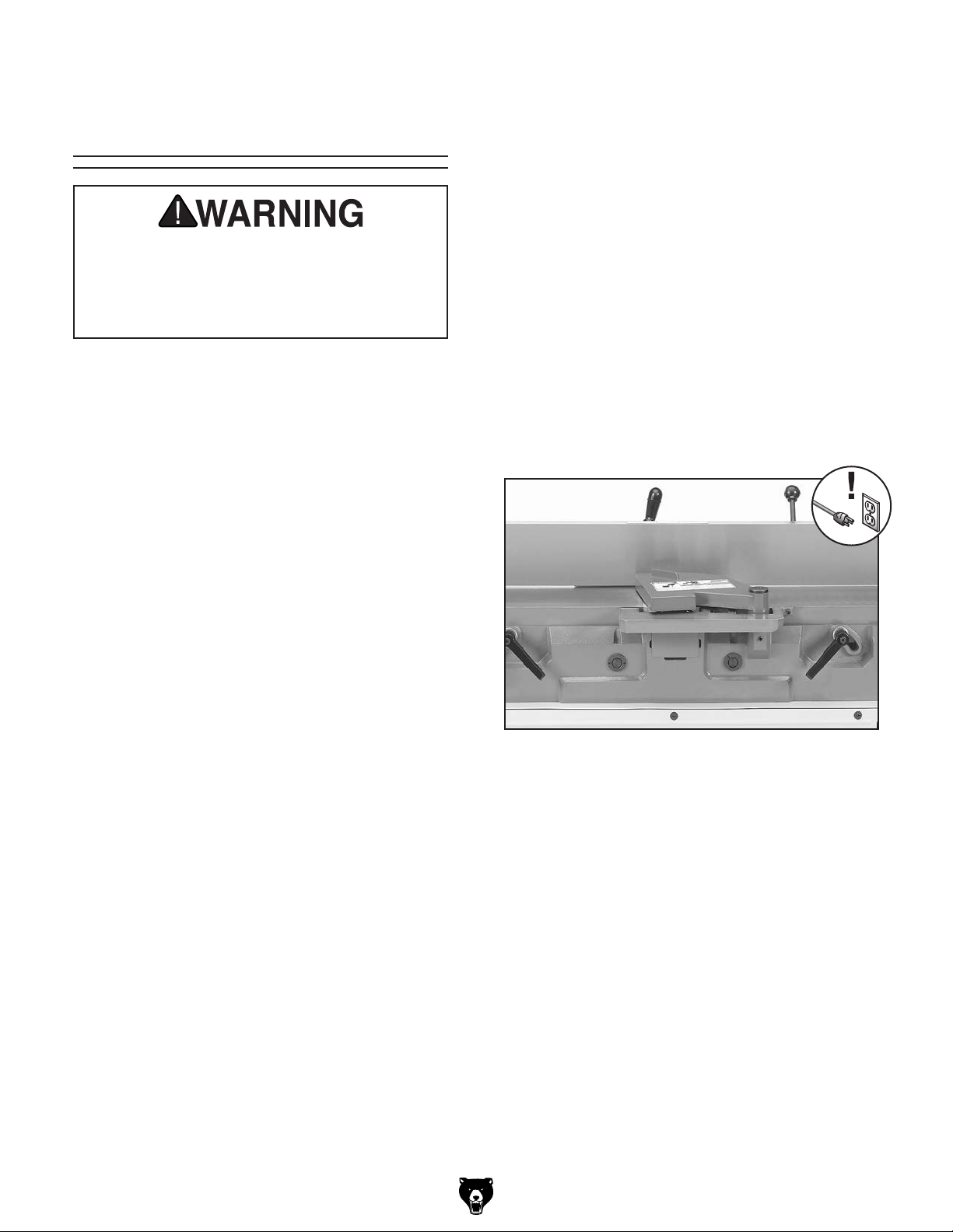
Checking/Adjusting
Cutterhead Guard
The cutterhead guard is a critical safety
feature of this jointer. You MUST verify its
operation before using the jointer! Failure
to properly install this guard will greatly
increase risk of serious personal injury.
The cutterhead guard is designed to reduce the
risk of accidental contact with hands or fingers
with the spinning cutterhead. When properly
installed and functioning correctly, the guard automatically rotates clear of the cutterhead during the
cutting operation and then springs back over the
cutterhead as soon as the operation is complete.
To check/adjust cutterhead guard:
DISCONNECT MACHINE FROM POWER!
1.
2. Loosen fence lock, move fence all the way
back, then tighten fence lock.
Pull cutterhead guard back and let it go. It
3.
should spring back over cutterhead and rest
against fence (see Figure 49).
— If cutterhead guard does spring back
over cutterhead and rest against fence,
cutterhead guard is properly tensioned.
Proceed to Step 7.
— If cutterhead guard does not spring back
over cutterhead and rest against fence,
proceed to Step 4.
In order to function as intended, the guard must
be installed as low as possible over the infeed
table without actually touching it (approximately
1
⁄16 " above infeed table), and it must have enough
spring tension at the mounting shaft to quickly
reposition itself against the fence after it is rotated
away from the cutterhead and released. Before
performing rabbeting operations, adjust guard
height to just clear outfeed table.
Items Needed Qty
Work Gloves ................................................. 1 Pr.
Hex Wrenches 4, 6mm
Straight Jaw Pliers 10"
................................ 1 Ea.
...................................... 1
Figure 49. Cutterhead guard against fence.
Model G0604Z (Mfd. Since 02/24)
-39-
Page 42

4. Put on work gloves and loosen cap screw
securing cutterhead guard clamp just enough
so cutterhead guard moves freely (see Figure
50). DO NOT remove cap screw.
Guard Clamp
Figure 50. Location of cutterhead guard clamp
and cap screw.
With cutterhead guard resting against fence,
5.
use straight-jaw pliers to rotate cutterhead
1
guard clamp a
⁄4 turn clockwise, then tighten
cap screw to secure guard clamp, as shown
in Figure 51.
Clockwise
Rotation
6. Pull cutterhead guard back and let it go. It
should spring back over cutterhead and rest
against fence.
— If cutterhead guard does spring back
over cutterhead and rest against fence,
cutterhead guard is properly tensioned.
Proceed to Step 7.
— If cutterhead guard does not spring back
over cutterhead and rest against fence,
repeat Steps 4–5 until properly adjusted,
then proceed to Step 7.
Verify cutterhead guard height is as low as
7.
possible (approximately 1⁄8" above infeed
table) without dragging on infeed table/rabbeting extension.
— If cutterhead guard is as low as possible
without dragging on infeed table/rabbeting
extension, cutterhead guard height is correct. No further adjustment is required.
— If cutterhead guard is not as low as pos-
sible or drags on infeed table/rabbeting extension, loosen set screw securing
cutterhead guard shaft, position cutterhead
1
guard until it is approximately
⁄8" above
infeed table, then tighten set screw (see
Figure 52).
Cap
Screw
Fence
Cutterhead
Guard Clamp
Figure 51. Rotating cutterhead guard clamp
(tables removed for clarity).
-40-
Figure 52. Location of cutterhead guard shaft
set screw.
Model G0604Z (Mfd. Since 02/24)
Page 43
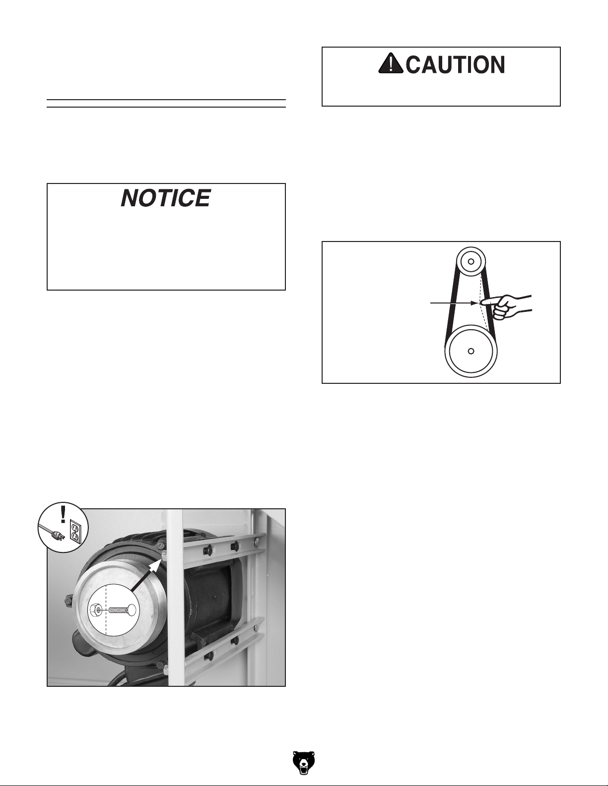
Tensioning/
Replacing V-Belt
To ensure optimum power transmission from
the motor to the cutterhead, the V-belt must be
in good condition (free from cracks, fraying and
wear) and properly aligned and tensioned.
After approximately 16 hours of operation, belt will stretch and seat into pulley grooves. The belt needs to be re-tensioned after this initial break-in period
to ensure optimum power transfer and
maximum overall life of the belt.
Items Needed Qty
Additional Person .............................................. 1
Replacement V-Belt (P0604Z224)
Phillips Head Screwdriver #2
Wrenches or Sockets 12, 13mm
..................... 1
............................ 1
.................1 Ea.
Belt and pulleys will be hot after operation.
Allow them to cool before handling.
5. Press belt with moderate pressure in cen-
ter to check belt tension. Belt is correctly
tensioned when there is approximately
deflection when pushed (see Figure 54).
— If there is more than 1⁄4" deflection when
you check belt tension, repeat the tensioning procedure until it is correct.
Cutterhead Pulley
Approximately
1
/4" Deflection
Motor Pulley
1
⁄4"
Tensioning V-Belt
1. DISCONNECT MACHINE FROM POWER!
2. Remove cabinet rear panel and belt guard.
3. Loosen hex nuts on carriage bolts securing
motor (see Figure 53). DO NOT completely
remove hex nuts.
x 4
Figure 54. Correct belt deflection when properly
tensioned.
Tighten motor mount hex nuts (see Figure
6.
53), and install cabinet rear panel and belt
guard.
Replacing V-Belt
1. DISCONNECT MACHINE FROM POWER!
2. Remove cabinet rear panel and belt guard.
3. Loosen hex nuts on carriage bolts securing
motor (see Figure 53).
Have another person lift motor as you remove
4.
belt and replace it with a new one. Make sure
ribs of belt are seated in pulley grooves.
Follow Steps 4–5 in Tensioning Belt proce-
5.
dure to set correct belt tension.
Figure 53. Motor adjustment location.
Press down on motor to keep tension on belt.
4.
Model G0604Z (Mfd. Since 02/24)
Tighten motor mount hex nuts (see Figure
6.
53), and install cabinet rear panel and belt
guard.
-41-
Page 44

Aligning Pulleys
Pulley alignment is another important factor in
power transmission and belt life. The pulleys
should be parallel to each other and in the same
plane (coplanar) for optimum performance.
The pulleys can be adjusted by loosening the
pulley set screws, aligning the pulleys, and
retightening the set screws.
Tools Needed Qty
Hex Wrench 3mm .............................................. 1
Straightedge 4'
Phillips Head Screwdriver #2
Wrenches or Sockets 12, 13mm
.................................................. 1
............................ 1
.................1 Ea.
Straightedge
Cutterhead
Touching
Evenly
To align pulleys:
DISCONNECT MACHINE FROM POWER!
1.
2. Remove cabinet rear panel and belt guard,
then move fence all the way back.
Place straightedge against pulleys to check
3.
their alignment (see Figure 55).
Note: This can also be done visually (without
a straightedge) if you do not have a straightedge available that will fit; however, the
most accurate results will come from using a
straightedge.
Motor
Figure 55. Example of checking pulley
alignment.
— If they are not aligned, loosen set screws
on motor pulley as needed to align pulleys, then tighten set screws, as shown in
Figure 56.
Pulley
Straightedge
x 2
-42-
Figure 56. Motor pulley set screw locations.
Replace cabinet rear panel and belt guard,
4.
then move fence to desired position.
Model G0604Z (Mfd. Since 02/24)
Page 45

Rotating/Replacing
Indexable Inserts
The Model G0604Z spiral cutterhead is equipped
with 4-sided indexable carbide inserts. Each
insert can be removed, rotated, and re-installed
to use any of its four cutting edges. If one cutting
edge becomes dull or damaged, simply rotate it
90º (see Figure 57) to use a sharp cutting edge.
Figure 57. Rotating indexable carbide inserts.
Cutterhead inserts are extremely sharp.
Wear work gloves to avoid the risk of serious personal injury during the following
steps in this section.
To replace or rotate indexable insert:
1. DISCONNECT MACHINE FROM POWER!
Set fence to 90° and move it all the way back.
2.
Remove cutterhead guard, and lower infeed
3.
table as far down as it will go.
Remove belt guard to expose cutterhead
4.
pulley.
Rotate pulley as needed to make inserts
5.
accessible for removal or rotation.
Remove any sawdust from head of carbide
6.
insert Torx screw.
Each insert has a reference dot on one corner.
As the insert is rotated, the reference dot location
can be used as an indicator of which edges are
used and which are new. Replace insert when the
reference dot has been used and rotated back to
its starting position.
Items Needed
• Work Gloves ......................................... 1 Pair
• Safety Glasses (per person)........................ 1
Flat Hd Torx Screws
•
T20 M6-1 x 15 ..............................As Needed
Indexable Carbide Inserts
•
14 x 14 x 2mm ..............................As Needed
Torx Bit T-20 1⁄4" Shank ............................... 1
•
• T-Handle Bit Driver 1⁄4" ................................. 1
• Wrench or Socket 10mm ............................. 1
• Hex Wrench 4mm ........................................ 1
• Torque Wrench 0–50 in.-lb. ......................... 1
• Clean Shop Rags .........................As Needed
• Degreaser .....................................As Needed
• Light Machine Oil .........................As Needed
Put on work gloves to protect fingers and
7.
hands.
Remove Torx screw and indexable insert
8.
(see Figure 58).
Cutterhead
Insert
Torx
Screw
Figure 58.
Example of cutterhead inserts and
Torx screws.
Model G0604Z (Mfd. Since 02/24)
-43-
Page 46

9. Clean all dust and dirt off insert and cutterhead
pocket from which insert was removed, and
replace insert so a fresh, sharp edge is facing
outward.
Checking/Adjusting
Table Parallelism
— If all four insert cutting edges have been
used, replace insert with a new one.
Always position reference dot in same
position when installing a new insert to aid
in rotational sequencing.
Note: Proper cleaning is critical to achiev-
ing a smooth finish. Dirt or dust trapped
between insert and cutterhead will slightly
raise insert, and make noticeable marks on
your workpieces the next time you cut.
Lubricate Torx screw threads with a light
10.
machine oil, wipe excess oil off threads, and
torque Torx screw to 48–50 inch pounds.
Note: Excess oil may squeeze between
insert and cutterhead or in screw hole, thereby lifting insert or screw slightly and affecting
workpiece finishes.
Install belt guard and raise infeed table.
11.
If the tables are not parallel with the cutterhead or
each other, then poor cutting results and kickback
can occur.
Needed Qty
Tools
Straightedge 4' .................................................. 1
Hex Wrench 4mm
Hammer
Center Punch
............................................. As Needed
.............................................. 1
..................................... As Needed
Checking Outfeed Table
1. DISCONNECT MACHINE FROM POWER!
2. Remove cutterhead guard, fence, and rear
cabinet panel.
Loosen outfeed table lock, and loosen jam
3.
nuts and positive stop bolts located on the
rear of machine just behind outfeed table
(see Figure 59).
Install cutterhead guard back over cutterhead,
12.
making sure that spring tension in guard
is properly set so guard springs back over
cutterhead when it is pulled back and
released, as shown in Checking/Adjusting
Cutterhead Guard on Page 39.
Stop Bolts
Figure 59. Outfeed table positive stop bolts.
-44-
Model G0604Z (Mfd. Since 02/24)
Page 47

Black Lines Represent Straightedge
Rotate motor pulley so that you can access
4.
cutterhead body with straightedge between
insert rows (see Figure 60).
Place straightedge on outfeed table so it hangs
5.
over cutterhead, then lower outfeed table
until straightedge just touches cutterhead
body (see Figure 60).
Straightedge
Outfeed Table
Checking Infeed Table
1. Follow all steps in Checking Outfeed Table
on Page 44 to first make sure that outfeed
table is parallel with cutterhead.
Set outfeed table height (see Setting Outfeed
2.
Table Height on Page 48).
Rotate cutterhead so inserts will not inter-
3.
fere, then place straightedge across infeed/
outfeed tables and adjust infeed table even
with outfeed table (see Figure 62).
Straightedge
Figure 60. Adjusting outfeed table even with
cutterhead body.
Place straightedge in positions shown in
6.
Figure 61. In each position, straightedge
should touch cutterhead and sit flat on outfeed
table.
Black Lines Represent
Straightedge Positions
From Overhead View
Figure 61. Straightedge positions for verifying if
outfeed table is parallel with cutterhead.
InfeedOutfeed
Figure 62. Infeed and outfeed tables set evenly.
4. Place straightedge in positions shown in
Figure 63. In each position, the straightedge
should sit flat against both outfeed table and
infeed table.
Positions from Overhead View
— If straightedge touches cutterhead body
and sits flat across outfeed table in each
position, then outfeed table is already
parallel with cutterhead. Follow Checking
Infeed Table instructions on this page.
— If straightedge does not touch cutterhead
Model G0604Z (Mfd. Since 02/24)
and sit flat on outfeed table in any of the
positions, then outfeed table is not parallel
with cutterhead. Perform Adjusting Table
Parallelism procedure on Page 46.
Figure 63. Straightedge positions for checking
infeed/outfeed table parallelism.
— If straightedge sits flat against both infeed
and outfeed tables, then tables are parallel. Install cutterhead guard, fence, and
rear cabinet panel.
— If straightedge does not sit flat against
both infeed and outfeed tables in any of
positions, proceed to Adjusting Table
Parallelism on Page 46.
-45-
Page 48

Adjusting Table Parallelism
For safe and proper cutting results, the tables must
be parallel with the cutterhead. Adjusting them to
be parallel is a task of precision and patience, and
may take up to one hour to complete. Luckily, this
is considered a permanent adjustment and should
not need to be repeated for the life of the machine.
Due to the complex nature of this task, we recommend that you double check the current table
positions to make sure that they really need to be
adjusted before starting.
IMPORTANT: The steps below are intended to
be performed directly after the steps involved in
checking the outfeed table parallelism. Do not
continue until you have performed those steps.
To adjust table parallelism:
Place straightedge on outfeed table so it hangs
1.
over cutterhead, and lower outfeed table until
straightedge just touches cutterhead body
(see Figure 64).
The tables have four eccentric bushings under
each corner that allow the tables to be adjusted
parallel. These eccentric bushings are locked in
place by set screws and adjust when rotated.
The correct order for adjusting the table parallelism is to first adjust the outfeed table parallel with
the cutterhead to within 0.010"-0.012", then adjust
the infeed table parallel with the outfeed table.
When setting the outfeed table, all measurements
must be made from the cutterhead body—NOT
the inserts.
Straightedge
Outfeed Table
Figure 64. Adjusting outfeed table even with
cutterhead body.
Remove top set screw from (4) eccentric
2.
bushings under outfeed table, and loosen set
screws underneath removed set screws (see
Figure 65).
x 4
-46-
Eccentric
Bushing
(1 of 4)
Figure 65. Eccentric bushing and set screw
location.
Model G0604Z (Mfd. Since 02/24)
Page 49

3. Place straightedge in one of the positions
shown in Figure 66, and adjust table by turning eccentric bushings as needed so that
straightedge touches cutterhead while lying
flat across outfeed table. Repeat this step
with each remaining straightedge position as
many times as necessary until outfeed table
is parallel with cutterhead to within 0.010"–
0.012".
Note: Setting outfeed table parallel to
cutterhead within 0.010"-0.012" will produce
high quality results. Going lower than this
number will produce minimal gain.
Straightedge
Outfeed Table
Infeed Table
Figure 67. Infeed and outfeed tables set evenly.
Place straightedge in one of the positions
8.
shown in Figure 68, and adjust eccentric
bushings under infeed table so straightedge
lies flat against both tables.
Black Lines Represent
Straightedge Positions
From Overhead View
Figure 66. Straightedge positions for verifying if
outfeed table is parallel with cutterhead.
Repeat Step 3 with each remaining straight-
4.
edge position as many times as necessary
until outfeed table is parallel with cutterhead.
Tighten/replace set screws in eccentric bush-
5.
ings on outfeed table.
Remove set screw from each of the (4)
6.
eccentric bushings under infeed table, and
loosen set screws underneath those removed
set screws.
Black Lines Represent Straightedge
Positions from Overhead View
Figure 68. Straightedge positions for checking
infeed/outfeed table parallelism.
Repeat Step 8 with each remaining straight-
9.
edge position as many times as necessary
until infeed table is parallel with outfeed table.
Tighten/install set screws in eccentric bush-
10.
ings on infeed table.
Perform Setting Outfeed Table Height on
11.
Page 48.
Rotate cutterhead so inserts will not inter-
7.
fere, then place straightedge across infeed/
outfeed tables and adjust infeed table even
with outfeed table (see Figure 67).
Model G0604Z (Mfd. Since 02/24)
-47-
Page 50

Setting Outfeed
Table Height
To help ensure safe operation and the best cutting
results, set the outfeed table height level with the
inserts when they are at top-dead-center (TDC). If
the outfeed table is set too low, the workpiece will
be tapered from front to back or there will be snipe
(a gouge in the end of the board that is uneven
with the rest of the cut). If the outfeed table is set
too high, the workpiece will hit the edge of the
outfeed table during operation, increasing the
chance of kickback.
Tools Needed Qty
Straightedge 4' .................................................. 1
Open-End Wrench 17mm
Hex Wrenches 3, 4, 8mm
Phillips Head Screwdriver #2
.................................................................. 1
Pliers
.................................. 1
.................................. 1
............................ 1
4. Place straightedge on outfeed table so it
hangs over cutterhead, then use motor pulley
to rotate cutterhead until one insert is at TDC
(its highest point during rotation), as shown in
Figures 70–71.
Top Dead
Center
Figure 70. Cutterhead insert at TDC.
Straightedge
To set outfeed table height:
DISCONNECT MACHINE FROM POWER!
1.
2. Remove cutterhead guard, fence, and rear
cabinet panel.
Loosen outfeed table lock, then loosen jam
3.
nuts and positive stop bolts located at rear
of machine just behind outfeed table (see
Figure 69).
Stop Bolts
Outfeed Infeed
Figure 71. Using straightedge to check outfeed
table height.
Use outfeed table adjustment lever to set
5.
outfeed table so insert barely touches straightedge, as shown in Figure 71.
Tighten outfeed table lock so outfeed table
6.
will not move during operation.
Tighten positive stop bolts, then jam nuts.
7.
8. Install cutterhead guard, fence, and rear
cabinet panel.
Figure 69. Outfeed table positive stop bolts.
-48-
Model G0604Z (Mfd. Since 02/24)
Page 51

Adjusting Infeed
Calibrating Depth
Table Stop Bolts
The infeed table on the Model G0604Z has positive stop bolts that, when properly set up, allow
the operator to quickly adjust the infeed table
between finish/final cuts and shaping/heavy cuts.
\We recommend setting the minimum depth of cut
1
⁄32" and the maximum depth of cut to 1⁄8" for
to
most operations.
DO NOT exceed 1⁄8" cut per pass on this
machine or the risk of kickback and serious
injury will be greatly increased!
Each positive stop bolt controls top or bottom
range of table movement (see Figure 72). Jam
nuts lock positive stop bolts in position so they will
not move during operation.
Scale
The depth scale can be calibrated or "zeroed" to
make sure the cutting depth shown on the scale
matches the actual cutting depth (per pass).
Tools Needed Qty
Straightedge 4' .................................................. 1
Hex Wrench 2.5mm
To calibrate depth scale:
DISCONNECT MACHINE FROM POWER!
1.
Set outfeed table height (see Setting Outfeed
2.
Table Height on Page 48).
Rotate cutterhead until insert is no longer at
3.
TDC, extend straightedge over both tables,
then raise infeed table even with outfeed
table, as shown in Figure 73.
........................................... 1
Top Height
Stop Bolt
Bottom Height
Stop Bolt
Figure 72. Positive stop bolts for infeed table.
Tools Needed Qty
Open-End Wrench 17mm .................................. 1
Slip-Joint Pliers
.................................................. 1
Straightedge
InfeedOutfeed
Figure 73. Infeed table even with outfeed table.
4. Loosen flat head cap screw on depth scale
pointer, adjust scale pointer to zero, then
secure (see Figure 74).
Depth
Scale
Pointer
Model G0604Z (Mfd. Since 02/24)
Figure 74. Depth scale pointer adjusted to zero.
-49-
Page 52

Setting Fence Stops
Setting 90° Fence Stop
1. DISCONNECT MACHINE FROM POWER!
The fence stops simplify the task of adjusting the
fence to 45˚, 90˚, and 135˚ (45˚ outward).
Tools Needed Qty
Square 45°, 90° ........................................... 1 Ea.
Phillips Head Screwdriver #2
Sliding Bevel
Open-End Wrenches 10mm
Hex Wrench 4mm
...................................................... 1
.............................................. 1
............................ 1
.............................. 2
Setting 45° Fence Stop
1. DISCONNECT MACHINE FROM POWER!
2. Loosen fence tilt lock knob and tilt fence
approximately 45° onto stop bolt, then place
45° square against fence and table (see
Figure 75).
2. Loosen set screw in plunger lock collar, then
loosen fence tilt lock (see Figure 77).
Using a 90° square, adjust fence to 90° posi-
3.
tion, then tighten set screw in plunger lock
collar.
If required, loosen Phillips head screw on
4.
fence tilt scale, adjust fence tilt scale indicator
to 0°, then secure (see Figure 77).
Plunger Lock Collar
Fence Tilt Lock
Fence Tilt Scale
Fence Tilt
Scale Indicator
Figure 75. Fence adjusted 45˚.
3. Loosen jam nut on 45° positive stop bolt
shown in Figure 76.
45° Positive
Stop Bolt
Jam Nut
Figure 76. 45° positive stop bolt location.
Figure 77. Adjusting fence to 90˚.
Setting 135° Fence Stop
1. DISCONNECT MACHINE FROM POWER!
2. Loosen fence tilt lock, and position fence
against 135° stop bolt.
Loosen jam nut on 135˚ positive stop bolt
3.
(see Figure 78).
135° Positive
Stop Bolt
Jam Nut
Figure 78. Adjusting fence 135˚.
4. Adjust stop bolt until fence is exactly 45°
while resting on bolt (verify angle with 45°
square), then tighten jam nut loosened in
Step 3.
-50-
Adjust 135˚ positive stop bolt until fence is
4.
135° while resting on bolt (check angle with a
45º square set to 135°), then tighten jam nut
loosened in Step 3.
Model G0604Z (Mfd. Since 02/24)
Page 53

These pages are current at the time of printing. However, in the spirit of improvement, we may make changes to the electrical systems of future machines. Compare the manufacture date of your machine to the one
stated in this manual, and study this section carefully.
If there are differences between your machine and what is shown in this section, call Technical Support at
(570) 546-9663 for assistance BEFORE making any changes to the wiring on your machine. An updated
wiring diagram may be available.
number and manufacture date of your
machine before calling. This information can be found on the main machine label.
SECTION 8: WIRING
Note: Please gather the serial
Wiring Safety Instructions
SHOCK HAZARD. Working on wiring that is con-
nected to a power source is extremely dangerous.
Touching electrified parts will result in personal
injury including but not limited to severe burns,
electrocution, or death. Disconnect the power
from the machine before servicing electrical components!
MODIFICATIONS. Modifying the wiring beyond
what is shown in the diagram may lead to unpredictable results, including serious injury or fire.
This includes the installation of unapproved aftermarket parts.
WIRE CONNECTIONS. All connections must
be tight to prevent wires from loosening during
machine operation. Double-check all wires disconnected or connected during any wiring task to
ensure tight connections.
CIRCUIT REQUIREMENTS. You MUST follow
the requirements at the beginning of this manual
when connecting your machine to a power source.
WIRE/COMPONENT DAMAGE. Damaged wires
or components increase the risk of serious personal injury, fire, or machine damage. If you notice
that any wires or components are damaged while
performing a wiring task, replace those wires or
components.
MOTOR WIRING. The motor wiring shown in
these diagrams is current at the time of printing
but may not match your machine. If you find this
to be the case, use the wiring diagram inside the
motor junction box.
CAPACITORS/INVERTERS. Some capacitors
and power inverters store an electrical charge for
up to 10 minutes after being disconnected from
the power source. To reduce the risk of being
shocked, wait at least this long before working on
capacitors.
EXPERIENCING DIFFICULTIES. If you are experiencing difficulties understanding the information
included in this section, contact our Technical
Support at (570) 546-9663.
The photos and diagrams
included in this section are
best viewed in color. You
can view these pages in
color at www.grizzly.com.
Model G0604Z (Mfd. Since 02/24)
-51-
Page 54

110 VAC
Neutral
Hot
Wiring Diagram 110V
N
L
Ground
5-20 Plug
5
N1
3
6
L1
L1
1L1 5L3 13NO
A1
3L2
4
Ground
N1
N1
L1
A2
N1
N1
N1
L
N
N1
14
L1
2
5
6
L1
3
POWER SWITCH (SA1)
KEDU HY-18N 20A
L1
4
N1
N1
4
4
1
CB-10
2
5
X1
X2
5
N1
PL-BA9
5
5
START BUTTON (SB2)
NHD NLB22-F10GI
CONTROL PANEL
Ground
3
2
CB-10
1
N1
STOP BUTTON (SB1)
NHD NLB22-F11RI
3
X1
PL-BA9
X2
4
4
CB-01
3
L1
L1
NO
54 62
NHD C-18D10
110V
Contactor
61
53
NC
3
2T1 6T3
4T2
OL Relay
17
18
NHD NTH-21
20
21
14NO
R
O
5
5
6
98
97
2T1 6T34T2
U1
96 95
5
W1
MAG SWITCH 110V
NHD MS-18D111D7N212P
Ground
W1
U1
Motor
Junction Box
W1
U1
W1
U1
W2
S Capacitor
U2
300VAC
R Capacitor
CBB60 35μF
450VAC
Ground
MOTOR 110V
CD60
150μF
-52-
READ ELECTRICAL SAFETY
ON PAGE 51!
Model G0604Z (Mfd. Since 02/24)
Page 55
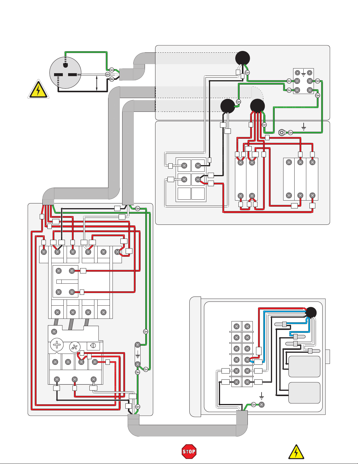
Ground
220 VAC
Wiring Diagram 220V
5
3
G
6-15 Plug
N1
220
VAC
Hot
Hot
L1
N1
L
N
N1
POWER SWITCH (SA1)
KEDU HY-18N 20A
14
L1
2
5
6
L1
3
N
L
4
4
1
CB-10
2
5
N1
4
X1
X2
5
N1
PL-BA9
5
5
L1
N1
START BUTTON (SB2)
NHD NLB22-F10GI
CONTROL PANEL
Ground
Ground
3
2
CB-10
1
N1
STOP BUTTON (SB1)
NHD NLB22-F11RI
3
X1
PL-BA9
X2
4
4
CB-01
3
L1
6
L1
L1
A1
2T1 6T3
18
20
98
2T1 6T34T2
U1
4
1L1 5L3 13NO
3L2
61
53
NC
NO
54 62
4T2
OL Relay
17
NHD NTH-11
21
97
5
N1
N1
L1
Contactor
NHD C-11D10
220V
3
14NO
R
O
5
5
96 95
W1
N1
N1
A2
Motor
Junction Box
Ground
W2
6
W1
U1
W1
U1
U2
W1
U1
Ground
S Capacitor
CD60
150μF
300VAC
R Capacitor
CBB60 35μF
450VAC
MAG SWITCH 220V
NHD MS-11D111G7N112P
Model G0604Z (Mfd. Since 02/24)
MOTOR 220V
READ ELECTRICAL SAFETY
ON PAGE 51!
-53-
Page 56

Electrical Components
Figure 79. Control panel wiring.
Figure 80. Motor junction box (110V).
Figure 81. Magnetic switch wiring (110V).
-54-
READ ELECTRICAL SAFETY
ON PAGE 51!
Model G0604Z (Mfd. Since 02/24)
Page 57

We do our best to stock replacement parts when possible, but we cannot guarantee that all parts shown
are available for purchase. Call (800) 523-4777 or visit www.grizzly.com/parts to check for availability.
67
77
109
Conversion)
139
SECTION 9: PARTS
Main
141
140
51
46
47
138
57
55
84
74
136
137
52
56
61
56
85
87
86
45
23
18
24
25
113
Conversion)
26
40
39
37
38
36
32
(220V
142X
80
79
76
43
81
35
69
44
53
42
27
73
34
90
89
48
41
28
29
30
31
33
117
54
94
88
81
83
73
82
74
132
112
104
8
9
10
111
118
69
131
14
13
115
71
70
22
21
97
133
98
15
116
69
20
10
11
68
75
16
19
142
17
114
143
144
12
106
105
103
91
5
100
102
127
129
135
134
7
6
11
110
101
119
120
96
72
92
126
128
130
2
4
1
108
107
99
95
93
(220V
136X
137X
49
50
58
60
62
63
64
78
Model G0604Z (Mfd. Since 02/24)
BUY PARTS ONLI NE AT GRIZZLY.COM!
Scan QR code to visit our Parts Store.
65
66
-55-
Page 58

Main Parts List
REF PART # DES CRIP TI ON REF P ART # DES CRIP TI ON
54 P0604Z054 CHI P DEFL ECTOR 108 P0604Z108 CUTTERHEAD PULLEY WASHER
1 P0604Z001 BUSHI NG 55 P0604Z055 LOCK NUT M12-1.75
2 P0604Z002 LEVER HANDLE M10-1. 5 X 80, 66L 56 P0604Z056 ADJUSTABLE BLOCK
4 P0604Z004 ECCENTRI C SHAFT 57 P0604Z057 PIVOT BRACKET
5 P0604Z005 SET SCREW M6-1 X 16 58 P0604Z058 LEVER HANDLE M12-1.75 X 25, 329L
6 P0604Z006 SET SCREW M8-1. 25 X 12 60 P0604Z060 CAP SCREW M8-1.25 X 40
7 P0604Z007 FENCE CARRI AGE 61 P0604Z061 CLAMP PLATE
8 P0604Z008 HEX NUT M6- 1 62 P0604Z062 CAP SCREW M8-1.25 X 80
9 P0604Z009 HEX BOLT M6-1 X 25 63 P0604Z063 GUARD CL AMP
10 P0604Z010 SHAFT W/ HO LES 64 P0604Z064 CUTTERHEA D GUA RD
11 P0604Z011 CAP SCREW M8-1.25 X 30 65 P0604Z065 TORSION SPRING
12 P0604Z012 COLLAR 66 P0604Z066 ROLL PIN 3 X 16
13 P0604Z013 HEX NUT M8 -1 . 2 5 67 P0604Z067 SPRING RETAINER
14 P0604Z014 FLAT WA SHE R 8MM 68 P0604Z068 MEDI UM ADJ USTME NT SCRE W M10- 1. 5 X 50
15 P0604Z015 ECCENTRI C S HAFT 69 P0604Z069 HE X NUT M10 -1 . 5
16 P0604Z016 FENCE GIB 70 P0604Z070 SET SCREW M6-1 X 10 CONE-PT
17 P0604Z017 CAP SCREW M5-.8 X 16 71 P0604Z071 SET SCREW M6-1 X 10
18 P0604Z018 FENCE SUPPPORT 72 P0604Z072 MEDI UM A DJ USTMENT S CREW M1 0-1 . 5 X 1 10
19 P0604Z019 FLAT WA SHE R 10MM 73 P0604Z073 TORSI ON SPRING
20 P0604Z020 CAP SCREW M10-1.5 X 30 74 P0604Z074 TORSION SPRING
21 P0604Z021 HEX NUT M12-1.75 75 P0604Z075 TABLE BASE
22 P0604Z022 FLAT WASHER 14 X 38 X 5MM 76 P0604Z076 CHIP BREAKER
23 P0604Z023 I NDE X P I N K NOB 77 P0604Z077 FLAT WA SHE R 6MM
24 P0604Z024 ROLL PIN 3 X 30 78 P0604Z078 HEX BOLT M6-1 X 12
25 P0604Z025 COMPRESSION SPRI NG 1 X 10 X 24 79 P0604Z079 ADJUSTABLE HANDLE M8-1. 25 X 30, 106L
26 P0604Z026 I NDE X P I N S HAFT 80 P0604Z080 FLAT WASHER 9 X 30 X 5MM
27 P0604Z027 SWIVEL 81 P0604Z081 ECCENTRI C B USHI NG
28 P0604Z028 HEX BOLT M6-1 X 25 82 P0604Z082 TABLE SHAFT 20 X 234MM
29 P0604Z029 HEX NUT M6 -1 83 P0604Z083 SET SCREW M8-1. 25 X 10
30 P0604Z030 SET SCREW M8-1.25 X 12 84 P0604Z084 TABLE SHAFT W/HOLES 20 X 234MM
31 P0604Z031 LOCK COLLAR 85 P0604Z085 POINTER
32 P0604Z032 SET SCREW M8-1.25 X 12 86 P0604Z086 FLAT HD SCR M5-.8 X 10
33 P0604Z033 LOCK COLLAR 87 P0604Z087 ROLL PIN 3 X 10
34 P0604Z034 CLAMP 88 P0604Z088 HEIGHT SCALE
35 P0604Z035 THREADE D CLAMP 89 P0604Z089 RIVET 2 X 4 NAMEPLATE, STEEL
36 P0604Z036 PHLP HD SCR M6-1 X 16 90 P0604Z090 MEDI UM ADJ USTME NT SCRE W M10- 1. 5 X 90
37 P0604Z037 FLAT WA SHE R 6MM 91 P0604Z091 HEX BOLT M6-1 X 25
38 P0604Z038 POINTER 92 P0604Z092 LOCK WASHER 6MM
39 P0604Z039 FLAT WASHER 6.5 X 16 X 3 93 P0604Z093 BUMPER
40 P0604Z040 ADJUSTABLE HANDLE M10-1. 5 X 40, 111L 94 P0604Z094 SPRING PLATE
41 P0604Z041 FLAT WA SHE R 8MM 95 P0604Z095 OUTFEED TABLE
42 P0604Z042 LOCK WASHER 8MM 96 P0604Z096 OUTFEED TABLE LIP
43 P0604Z043 CAP SCREW M8-1.25 X 25 97 P0604Z097 FLAT WA SHE R 5MM
44 P0604Z044 FLANGE BOLT M6-1 X 12 98 P0604Z098 CAP SCREW M5-.8 X 16
45 P0604Z045 CONTROL PANEL BOX 99 P0604Z099 REAR BEARING PILLOW BLOCK
46 P0604Z046 CONTROL PANEL 100 P0604Z100 BALL BEARING 6004-2RS
47 P0604Z047 PHLP HD SCR M4-. 7 X 8 101 P0604Z101 SPI RAL CUTTERHE AD 6"
48 P0604Z048 CONTROL PANEL PEDESTAL 102 P0604Z102 KEY 6 X 6 X 32
49 P0604Z049 INFEED TABLE 103 P0604Z103 INT RETAI NI NG RI NG 42MM
50 P0604Z050 TABLE SHAFT 20 X 151MM 104 P0604Z104 FRONT BEARING PILLOW BLOCK
51 P0604Z051 RABBETING TABLE 105 P0604Z105 LOCK WASHER 8MM
52 P0604Z052 CAP SCREW M6-1 X 20 106 P0604Z106 CAP SCREW M8-1.25 X 80
53 P0604Z053 CAP SCREW M5-.8 X 12 107 P0604Z107 CUTTERHEA D PULL EY
-56-
BUY PARTS ONLI NE AT GRIZZLY.COM!
Scan QR code to visit our Parts Store.
Model G0604Z (Mfd. Since 02/24)
Page 59

Main Parts List (Cont.)
REF P ART # DE SCRIP TIO N REF P ART # DES CRIP TI ON
130 P0604Z130 HEX WRENCH 8 MM 144 P0604Z144 CONTROL PANEL CORD 18G 5W 94"
109 P0604Z109 HEX BOLT M8-1.25 X 25 131 P0604Z131 WRENCH 8 X 10 MM OPEN-E NDS
110 P0604Z110 PHLP HD SCR M6-1 X 10 132 P0604Z132 WRENCH 12 X 14MM OPEN-ENDS
111 P0604Z111 FLA T WAS HER 6MM 133 P0604Z133 PUSH BLOCK
112 P0604Z112 TI LT S CALE 134 P0604Z134 DRI V ER BI T TO RX T20
113 P0604Z113 KNOB M10-1. 5, D32, BALL 135 P0604Z135 T-HANDL E TO RX T20
114 P0604Z114 STUD-UDE M10-1.5 X 130, 15, 18 136 P0604Z136 STOP BUTTON NHD NLB22-F10GI AC110V RED
115 P0604Z115 SCALE 136X P0604Z136X STOP BUTTON NHD NLB22-F10GI AC220V RED
116 P0604Z116 RIVET 2 X 4 NAMEPLATE, STEEL 137 P0604Z137 START BUTTON NHD NLB22-F10GI AC110V GRN
117 P0604Z117 FENCE 137X P0604Z137X START BUTTON NHD NLB22-F10GI AC220V GRN
118 P0604Z118 BALL BEARING 6004-2RS 138 P0604Z138 PADDL E S WI TCH KEDU HY 18
119 P0604Z119 INDEXABLE INSERT 14 X 14 X 2 139 P0604Z139 STRAIN RELIEF TYPE 3 M20-2.5 X 1. 5
120 P0604Z120 FLAT HD TORX T20 M6-1 X 12 140 P0604Z140 CARRIAGE BOLT M4-. 7 X 20
126 P0604Z126 HEX WRENCH 2 . 5 MM 141 P0604Z141 GROUND P LA TE
127 P0604Z127 HEX WRENCH 4 MM 142 P0604Z142 POWER CORD 14G 3W 98" 5-20P
128 P0604Z128 HEX WRENCH 5 MM 142X P0604Z142X POWER CORD 16G 3W 98" 6-15P
129 P0604Z129 HEX WRENCH 6 MM 143 P0604Z143 MOTOR CORD 14G 3W 31"
Model G0604Z (Mfd. Since 02/24)
BUY PARTS ONLI NE AT GRIZZLY.COM!
Scan QR code to visit our Parts Store.
-57-
Page 60

Cabinet
231
238-13
200
201
228
208
226
227
209
202
225
224
206
207
203
204
205
230
238-1
238-2
238-3
229
238
223
222
238-14
238-4
238-5
238-7
238-6
238-12
238-11
238-8
237-3
237-2
237
236
235
238-10
238-9
237-4
237-1
234
233
228-2
228-1
228-4
228-5
228-3
228-11
228-6
228-10
210
228-7
228-12
228-11
228-8
228-9
211
213
212
214
219
216
215
220
218
221
217
(220V
Conversion)
237X-3
237X-2
237X
237X-4
237X-1
232
-58-
BUY PARTS ONLI NE AT GRIZZLY.COM!
Scan QR code to visit our Parts Store.
Model G0604Z (Mfd. Since 02/24)
Page 61

Cabinet Parts List
REF P ART # DES CRIP TI ON REF PART # DES CRIP TI ON
228-8 P0604Z228-8 CENTRI FUGA L S WI TCH CO NTACT 238-14 P0604Z238-14 HEX BOLT M8-1. 25 X 50
200 P0604Z200 PHLP HD SCR M5-. 8 X 16 228-9 P0604Z228-9 CENTRI FUG A L S WI TCH
201 P0604Z201 FL AT WAS HER 5 MM 228-10 P0604Z228-10 TERMINAL BAR 6P
202 P0604Z202 REAR PANEL 228-11 P0604Z228-11 TAP SCREW M4 X 16
203 P0604Z203 FLANGE SCREW M6-1 X 12 228-12 P0604Z228-12 JUNCTION BOX COVER
204 P0604Z204 BELT GUARD 229 P0604Z229 CAP SCREW M8-1.25 X 25
205 P0604Z205 CABINET 230 P0604Z230 FLA T WAS HE R 8MM
206 P0604Z206 FL AT WAS HER 6 MM 231 P0604Z231 HE X NUT M5- . 8
207 P0604Z207 HE X NUT M6- 1 232 P0604Z232 S WI TCH MO UNTI NG PL A TE
208 P0604Z208 PHLP HD SCR M5-. 8 X 16 233 P0604Z233 FL A T WAS HER 6MM
209 P0604Z209 FL AT WAS HER 5 MM 234 P0604Z234 PHLP HD SCR M6-1 X 10
210 P0604Z210 DUS T CHUTE 4" 235 P0604Z235 FLAT WA SHE R 5MM
211 P0604Z211 HE X NUT M8- 1. 25 236 P0604Z236 PHLP HD SCR M5-. 8 X 12
212 P0604Z212 FL AT WAS HER 8 MM 237 P0604Z237 MAG SWITCH ASSY 110V
213 P0604Z213 SLEEVE 237-1 P0604Z237-1 FRONT MAG SWITCH COVER
214 P0604Z214 WHEEL 13 X 76 X 30MM 237-2 P0604Z237-2 OL RELAY NHD NTH-21 17-21A
215 P0604Z215 HEX BOLT M8-1. 25 X 65 237-3 P0604Z237-3 REA R MAG S WI TCH CO VE R
216 P0604Z216 MOTOR BRACKET 237-4 P0604Z237-4 CO NTA CTOR NHD NTH C- 18D +CA 1 -D1 1
217 P0604Z217 FLANGE NUT M8-1. 25 237X P0604Z237X MAG SWITCH ASSY 220V
218 P0604Z218 CARRI AGE BOLT M8-1.25 X 25 237X-1 P0604Z237X-1 FRONT MAG SWITCH COVER
219 P0604Z219 CARRI AGE BOLT M8-1.25 X 30 237X-2 P0604Z237X-2 OL RELAY NHD NTH-11 8-11A
220 P0604Z220 FL AT WAS HER 8 MM 237X-3 P0604Z237X-3 REA R MAG S WI TCH COVE R
221 P0604Z221 HE X NUT M8- 1. 25 237X-4 P0604Z237X-4 CONTA CTOR NHD NTH C- 1 1D + CA1 -D1 1
222 P0604Z222 ADJUSTABLE FOOT M10-1.5 X 45 238 P0604Z238 PEDAL ASSEMBLY
223 P0604Z223 HE X NUT M10 -1 . 5 238-1 P0604Z238-1 HEX NUT M8-1 . 2 5
224 P0604Z224 POLY V-BELT A1120LI 238-2 P0604Z238-2 FL A T WAS HER 8 MM
225 P0604Z225 MOTOR PULLEY 238-3 P0604Z238-3 FLAT WA SHE R 8MM
226 P0604Z226 SET SCREW M6-1 X 6 238-4 P0604Z238-4 HEX NUT M10 - 1. 5
227 P0604Z227 KEY 6 X 6 X 25 238-5 P0604Z238-5 FLAT WA SHE R 1 0MM
228 P0604Z228 MOTOR 1HP 110/220V 1-PH 238-6 P0604Z238-6 PEDAL BRACKET
228-1 P0604Z228-1 MOTO R FAN COV ER 238-7 P0604Z238-7 TROLLEY BRACKET
228-2 P0604Z228-2 MOTO R FAN 238-8 P0604Z238-8 HEX BOLT M8-1. 25 X 100
228-3 P0604Z228-3 S CAPACI TOR 150M 300V 2 X 3-1/2 238-9 P0604Z238-9 EX T RETA I NI NG RI NG 13MM
228-4 P0604Z228-4 R CAPACITOR 35M 450V 1-3/ 4 X 3-5/8 238-10 P0604Z238-10 FLAT WASHER 14 X 30 X 3
228-5 P0604Z228-5 J UNCTI O N BO X 238-11 P0604Z238-11 CAPTIVE PI N
228-6 P0604Z228-6 BALL BEARING 6024-2RS FRONT 238-12 P0604Z238-12 HEX BOLT M10-1.5 X 55
228-7 P0604Z228-7 BALL BEARING 6023-2RS REAR 238-13 P0604Z238-13 PEDAL
Model G0604Z (Mfd. Since 02/24)
BUY PARTS ONLI NE AT GRIZZLY.COM!
Scan QR code to visit our Parts Store.
-59-
Page 62

301
REF PART # DES CRIPTI ON REF P ART # DES CRI PTION
306 P0604Z306 TOUCH UP PAINT, GRIZZLY BEI GE
Labels & Cosmetics
302
303
304
311
305
306
307
310
308
309
301 P0604Z301 CUTTERHEAD G UARD LABE L 307 P0604Z307 GRIZZLY NAMEPLATE - SMALL
302 P0604Z302 FENCE/CUTTERHEAD LABEL 308 P0604Z308 MODEL NUMBER LABEL
303 P0604Z303 CONTROL PANEL FACE LABEL 309 P0604Z309 GRIZZLY.COM LABEL
304 P0604Z304 ELECTRICITY LABEL 310 P0604Z310 TOUCH UP PAINT, GRIZZLY GREEN
305 P0604Z305 COMBO WARNING LABEL 311 P0604Z311 MACHINE ID LABEL
Safety labels help reduce the risk of serious injury caused by machine hazards. If any label comes
off or becomes unreadable, the owner of this machine MUST replace it in the original location
before resuming operations. For replacements, contact (800) 523-4777 or www.grizzly.com.
-60-
BUY PARTS ONLI NE AT GRIZZLY.COM!
Scan QR code to visit our Parts Store.
Model G0604Z (Mfd. Since 02/24)
Page 63

Grizzly Industrial, Inc. warrants every product it sells for a period of 1 year to the original purchaser from
the date of purchase. This warranty does not apply to defects due directly or indirectly to misuse, abuse,
negligence, accidents, repairs or alterations or lack of maintenance. This is Grizzly’s sole written warranty
and any and all warranties that may be implied by law, including any merchantability or fitness, for any particular purpose, are hereby limited to the duration of this written warranty. We do not warrant or represent
that the merchandise complies with the provisions of any law or acts unless the manufacturer so warrants.
In no event shall Grizzly’s liability under this warranty exceed the purchase price paid for the product and
any legal actions brought against Grizzly shall be tried in the State of Washington, County of Whatcom.
We shall in no event be liable for death, injuries to persons or property or for incidental, contingent, special,
or consequential damages arising from the use of our products.
The manufacturers reserve the right to change specifications at any time because they constantly strive to
achieve better quality equipment. We make every effort to ensure that our products meet high quality and
durability standards and we hope you never need to use this warranty.
In the event you need to use this warranty, contact us by mail or phone and give us all the details. We will
then issue you a “Return Number,’’ which must be clearly posted on the outside as well as the inside of
the carton. We will not accept any item back without this number. Proof of purchase must accompany the
merchandise.
Please feel free to write or call us if you have any questions about the machine or the manual.
Thank you again for your business and continued support. We hope to serve you again soon.
For further information about the
scan the QR
code below
WARRANTY & RETURNS
to be automatically directed to our warranty page.
warranty, visit https://www.grizzly.com/forms/warranty or
WARRANTY
Page 64

 Loading...