

Page 1

18" & 20"
SUPER HEAVY-DUTY
BANDSAWS
MODELS G0506/G0507/G0511
INSTRUCTION MANUAL
COPYRIGHT © AUGUST, 2002 BY GRIZZLY INDUSTRIAL, INC.
WARNING: NO PORTION OF THIS MANUAL MAY BE REPRODUCED IN ANY SHAPE
OR FORM WITHOUT THE WRITTEN APPROVAL OF GRIZZLY INDUSTRIAL, INC.
REVISED DECEMBER, 2003 PRINTED IN TAIWAN
Model G0506
Model G0507/G0511
Page 2

WARNING
Some dust created by power sanding, sawing, grinding, drilling, and other construction activities contains
chemicals known to the State of California to cause
cancer, birth defects or other reproductive harm.
Some examples of these chemicals are:
• Lead from lead-based paints.
• Crystalline silica from bricks, cement, and
other masonry products.
• Arsenic and chromium from chemically treated
lumber.
Your risk from these exposures varies, depending on
how often you do this type of work. To reduce your
exposure to these chemicals: work in a well ventilated
area, and work with approved safety equipment, such
as those dust masks that are specially designed to filter out microscopic particles.
Page 3

Table Of Contents
PAGE
1. SAFETY ......................................................................................................................................2
SAFETY RULES FOR ALL TOOLS ..................................................................................2-3
ADDITIONAL SAFETY INSTRUCTIONS FOR BANDSAWS................................................4
2. INTRODUCTION ..........................................................................................................................5
COMMENTARY ....................................................................................................................5
3. CIRCUIT REQUIREMENTS ........................................................................................................6
MODEL G0506/G0507 ..........................................................................................................6
MODEL G0511 ......................................................................................................................7
440V OPERATION ................................................................................................................7
GROUNDING ........................................................................................................................8
EXTENSION CORDS ............................................................................................................8
4. CONTROLS AND COMPONENTS..............................................................................................9
IDENTIFICATION ..................................................................................................................9
5. SET UP ......................................................................................................................................10
UNPACKING........................................................................................................................10
PIECE INVENTORY ............................................................................................................10
HARDWARE CHART ..........................................................................................................11
CLEAN UP ..........................................................................................................................12
SITE CONSIDERATIONS....................................................................................................12
TABLE..................................................................................................................................13
FENCE ................................................................................................................................13
DUST PORT ........................................................................................................................14
GUIDE POST ......................................................................................................................14
BLADE GUARD ..................................................................................................................15
BLADE GUIDES ..................................................................................................................15
BLADE TRACKING..............................................................................................................16
GULLET LINE ......................................................................................................................16
GUIDE BEARINGS ..............................................................................................................17
SUPPORT BEARINGS ........................................................................................................18
TABLE TILT ........................................................................................................................18
TABLE STOP ......................................................................................................................19
FOOT BRAKE......................................................................................................................20
TEST RUN ..........................................................................................................................20
BLADE TENSION ................................................................................................................21
FENCE ADJUSTMENT........................................................................................................22
BLADE LEAD ......................................................................................................................22
7. OPERATIONS............................................................................................................................23
BLADE SELECTIONS ....................................................................................................23-24
BLADE CHANGES ..............................................................................................................25
RIPPING ..............................................................................................................................26
STACKED CUTS ................................................................................................................26
RESAWING..........................................................................................................................27
8. MAINTENANCE ........................................................................................................................28
V-BELTS ..............................................................................................................................28
MISCELLANEOUS ..............................................................................................................28
TABLE..................................................................................................................................28
LUBRICATION ....................................................................................................................29
WHEEL BRUSH ..................................................................................................................29
WIRING DIAGRAMS ......................................................................................................30-31
9. CLOSURE ..................................................................................................................................32
G0506 MACHINE DATA......................................................................................................33
G0506 PARTS BREAKDOWN AND PARTS LISTS ......................................................34-40
G0507/G0511 MACHINE DATA ..........................................................................................41
G0507/G0511 PARTS BREAKDOWN AND PARTS LISTS ..........................................44-48
TROUBLESHOOTING GUIDE ............................................................................................49
WARRANTY AND RETURNS ............................................................................................50
Page 4

-2- 18" & 20" Super Heavy-Duty Bandsaws
Safety Instructions For Power Tools
SECTION 1: SAFETY
5. KEEP CHILDREN AND VISITORS
AWAY. All children and visitors should be
kept at a safe distance from work area.
6. MAKE WORKSHOP CHILD PROOF with
padlocks, master switches, or by removing
starter keys.
7. DO NOT FORCE TOOL. It will do the job
better and safer at the rate for which it was
designed.
8. USE RIGHT TOOL. Do not force tool or
attachment to do a job for which it was not
designed.
1. KEEP GUARDS IN PLACE and in working
order.
2. REMOVE ADJUSTING KEYS AND
WRENCHES. Form habit of checking to
see that keys and adjusting wrenches are
removed from tool before turning on.
3. KEEP WORK AREA CLEAN. Cluttered
areas and benches invite accidents.
4. DO NOT USE IN DANGEROUS ENVIRONMENT. Do not use power tools in
damp or wet locations, or where any flammable or noxious fumes may exist. Keep
work area well lighted.
For Your Own Safety Read Instruction
Manual Before Operating This Equipment
Indicates an imminently hazardous situation which, if not avoided,
WILL result in death or serious injury.
Indicates a potentially hazardous situation which, if not avoided,
COULD result in death or serious injury.
Indicates a potentially hazardous situation which, if not avoided,
MAY result in minor or moderate injury. It may also be used to alert
against unsafe practices.
This symbol is used to alert the user to useful information about
proper operation of the equipment.
The purpose of safety symbols is to attract your attention to possible hazardous conditions. This
manual uses a series of symbols and signal words which are intended to convey the level of
importance of the safety messages. The progression of symbols is described below. Remember
that safety messages by themselves do not eliminate danger and are not a substitute for proper
accident prevention measures.
NOTICE
Page 5

18" & 20" Super Heavy-Duty Bandsaws -3-
9. USE PROPER EXTENSION CORD. Make
sure your extension cord is in good condition. Conductor size should be in accordance with the chart below. The amperage
rating should be listed on the motor or tool
nameplate. An undersized cord will cause
a drop in line voltage resulting in loss of
power and overheating. Your extension
cord must also contain a ground wire and
plug pin. Always repair or replace extension cords if they become damaged.
Minimum Gauge for Extension Cords
10. WEAR PROPER APPAREL. Do not wear
loose clothing, gloves, neckties, rings,
bracelets, or other jewelry which may get
caught in moving parts. Non-slip footwear
is recommended. Wear protective hair covering to contain long hair.
11. ALWAYS USE SAFETY GLASSES. Also
use face or dust mask if cutting operation is
dusty. Everyday eyeglasses only have impact
resistant lenses, they are NOT safety glasses.
12. SECURE WORK. Use clamps or a vise to hold
work when practical. It is safer than using your
hand and frees both hands to operate tool.
13. DO NOT OVERREACH. Keep proper foot-
ing and balance at all times.
14. MAINTAIN TOOLS WITH CARE. Keep
tools sharp and clean for best and safest
performance. Follow instructions for lubricating and changing accessories.
Safety Instructions For Power Tools
15. USE RECOMMENDED ACCESSORIES.
Consult the owner’s manual for recommended accessories. The use of improper
accessories may cause risk of injury.
16. REDUCE THE RISK OF UNINTENTION-
AL STARTING. On machines with mag-
netic contact starting switches there is a
risk of starting if the machine is bumped or
jarred. Always disconnect from power
source before adjusting or servicing. Make
sure switch is in OFF position before reconnecting.
17. MANY WOODWORKING TOOLS CAN
“KICKBACK” THE WORKPIECE toward
the operator if not handled properly. Know
what conditions can create “kickback” and
know how to avoid them. Read the manual
accompanying the machine thoroughly.
18. CHECK DAMAGED PARTS. Before further use of the tool, a guard or other part
that is damaged should be carefully
checked to determine that it will operate
properly and perform its intended function.
Check for alignment of moving parts, binding of moving parts, breakage of parts,
mounting, and any other conditions that
may affect its operation. A guard or other
part that is damaged should be properly
repaired or replaced.
19. NEVER LEAVE TOOL RUNNING UNATTENDED. TURN POWER OFF. Do not
leave tool until it comes to a complete stop.
20. NEVER OPERATE A MACHINE WHEN
TIRED, OR UNDER THE INFLUENCE OF
DRUGS OR ALCOHOL. Full mental alert-
ness is required at all times when running
a machine.
21. NEVER ALLOW UNSUPERVISED OR
UNTRAINED PERSONNEL TO OPERATE THE MACHINE. Make sure any
instructions you give in regards to the
operation of the machine are approved,
correct, safe, and clearly understood.
LENGTH
AMP RATING 25ft 50ft 100ft
0-6 18 16 16
7-10 18 16 14
11-12 16 16 14
13-16 14 12 12
17-20 12 12 10
21-30 10 10 No
Page 6
-4- 18" & 20" Super Heavy-Duty Bandsaws
Additional Safety Instructions For Bandsaws
7. BLADE SHOULD BE RUNNING AT FULL
SPEED before beginning a cut.
8. ALWAYS FEED STOCK EVENLY AND
SMOOTHLY. Do not force or twist blade
while cutting, especially when sawing
small radii.
9. THIS MACHINE IS NOT DESIGNED TO
CUT METAL or other material except
wood.
10. DO NOT MANUALLY STOP OR SLOW
BLADE except with the foot brake. Allow it
to come to a complete stop before you
leave it unattended.
11. ALL INSPECTIONS, ADJUSTMENTS,
AND MAINTENANCE ARE TO BE DONE
WITH THE POWER OFF and the plug
pulled from the outlet. Wait for all moving
parts to come to a complete stop.
12. HABITS – GOOD AND BAD – ARE
HARD TO BREAK. Develop good habits
in your shop and safety will become second-nature to you.
13. IF AT ANY TIME YOU ARE EXPERIENC-
ING DIFFICULTIES PERFORMING THE
INTENDED OPERATION, STOP USING
THE BANDSAW! Then contact our service
department or ask a qualified expert how
the operation should be performed.
1. DO NOT OPERATE WITH DULL OR
BADLY WORN BLADES. Dull blades
require more effort to use and are difficult
to control. Inspect blades before each use.
2. NEVER POSITION FINGERS OR
THUMBS IN LINE WITH THE CUT.
Serious personal injury could occur.
3. DO NOT OPERATE THIS BANDSAW
WITHOUT WHEEL, PULLEY, AND
BLADE GUARDS IN PLACE.
4. WHEN REPLACING BLADES, make sure
teeth face down toward the table. The force
of the cut is always down. Make sure the
blade is properly tensioned after installing.
5. WORKPIECE SHOULD ALWAYS BE
FULLY SUPPORTED by the table or some
type of support fixture. Always support
round stock in a V-block.
6. DO NOT BACK WORKPIECE AWAY from
the blade while the saw is running. Plan
your cuts so you always cut out of the
wood. If you need to back the work out,
turn the bandsaw off or use the foot brake
and wait for the blade to come to a complete stop. Do not twist or put excessive
stress on the blade while backing work
away. Inspect blade for damage such as
kinks before continuing to use it. Discard it
if necessary.
No list of safety guidelines can be complete. Every shop environment is different.
Always consider safety first, as it applies
to your individual working conditions. Use
this and other machinery with caution and
respect. Failure to do so could result in
serious personal injury, damage to equipment or poor work results.
To operate this or any power tool safely and
efficiently, it is essential to become as familiar with it as possible. The time you invest
before you begin to use your bandsaw will
be time well spent. DO NOT operate this
machine until you are completely familiar
with the contents of this manual or serious
personal injury may occur.
Page 7
18" & 20" Super Heavy-Duty Bandsaws -5-
Grizzly Industrial, Inc. is proud to offer the 18"
and 20" Super Heavy-Duty Bandsaws. These
bandsaws are a part of Grizzly’s growing family of
fine woodworking machinery. When used according to the guidelines stated in this manual, you
can expect years of trouble-free, enjoyable operation, and proof of Grizzly’s commitment to customer satisfaction.
The chart below has been provided to help identify the differences between the 18" and 20"
Super Heavy-Duty Bandsaws.
We are also pleased to provide this manual with
the 18" and 20" Super Heavy-Duty Bandsaw. It
was written to guide you through assembly,
review safety considerations, and cover general
operating procedures. It represents our latest
effort to produce the best documentation possible. If you have any comments or criticisms that
you feel we should address in our next printing,
please write to us at:
Grizzly Industrial, Inc.
C
⁄O Technical Documentation
P.O. Box 2069
Bellingham, WA 98227
Most important, we stand behind our machines.
We have excellent regional service departments
at your disposal should the need arise.
SECTION 2: INTRODUCTION
If you have any service questions or parts
requests, please call or write to us at the location
listed below.
Grizzly Industrial, Inc
1203 Lycoming Mall Circle
Muncy, PA 17756
Phone:(570) 546-9663
Fax:(800) 438-5901
E-Mail: techsupport@grizzly.com
Web Site: http://www.grizzly.com
The specifications, drawings, and photographs
illustrated in this manual represent the 18" and
20" Super Heavy-Duty Bandsaw as supplied
when the manual was prepared. However, owing
to Grizzly’s policy of continuous improvement,
changes may be made at any time with no obligation on the part of Grizzly. Whenever possible,
though, we send manual updates to all owners of
a particular tool or machine. Should you receive
one, we urge you to insert the new information
with the old and keep it for reference
.
Commentary
Read the manual before
assembly and operation.
Become familiar with the
machine and its operation before beginning
any work. Serious personal injury may result if
safety or operational
information is not understood or followed.
Description
Motor
Phase
Size
G0506
2 HP
1-Phase
18"
G0507
3 HP
1-Phase
20"
G0511
5 HP
3-Phase
20"
Page 8
-6- 18" & 20" Super Heavy-Duty Bandsaws
Model G0506/G0507
The Model G0506/G0507 Bandsaw is pre-wired
for single-phase, 220V operation. Under normal
use, the Model G0506 2 HP motor draws approximately 12 amps. We recommend a 15 amp circuit. This includes a 15 amp circuit breaker, plug,
receptacle and wiring rated for at least 15 amps.
Under normal use, the Model G0507 3 HP motor
draws approximately 22 amps. We recommend a
25 amp circuit. This includes a 25 amp circuit
breaker, plug and wiring rated for at least 25
amps. These circuits should be satisfactory for
normal use, while providing enough protection
against damage caused by an overloaded circuit.
If frequent circuit failures occur when using the
bandsaw, contact our service department or your
local electrical contractor.
This bandsaw must be connected to its own dedicated circuit; it should not share a circuit with any
other machine. A standard 2-pole breaker is necessary for use with the Model G0506/G0507.
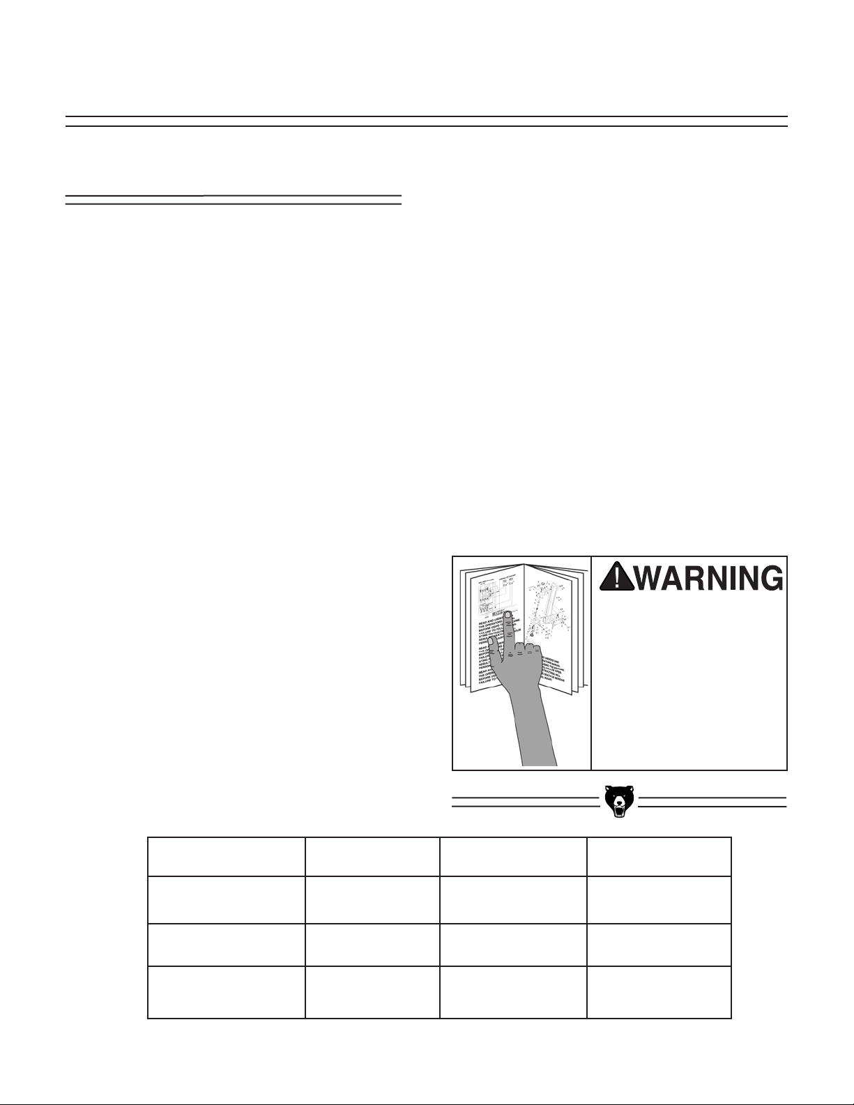
This bandsaw is not supplied with a cord and
power plug. We recommend using a NEMA-style
L6-25 plug and outlet similar to
Figure 1. You
may also “hard-wire” the bandsaw directly to your
panel, provided you place a disconnect switch
near the machine. Check the electrical codes in
your area for specifics on wiring requirements.
Please refer to the wiring diagram on
page 30 for
power hook-up information.
SECTION 3: CIRCUIT REQUIREMENTS
Figure 1. Typical 220V 3-prong plug and outlet.
Be sure that your particular electrical configuration complies with local and state codes.
The best way to ensure compliance is to
check with your local municipality or a
licensed electrician.
Page 9
18" & 20" Super Heavy-Duty Bandsaws -7-
Model G0511
The Model G0511 Bandsaw is pre-wired for 3phase, 220V operation. Under normal use, the 5
HP motor draws approximately 13 amps. We recommend using a 15 amp circuit, including a 15
amp circuit breaker, plug, receptacle and wiring
rated for at least 15 amps. If frequent circuit
breaker failures occur when using the bandsaw,
contact our service department.
This bandsaw must be connected to its own dedicated circuit. It should not share a circuit with any
other machine. A standard 3-pole breaker is necessary for use with the Model G0511.
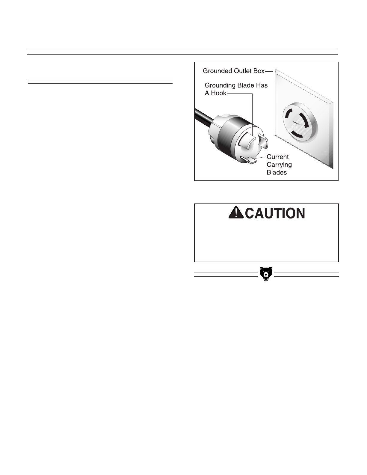
This bandsaw is not supplied with a cord and
power plug. We recommend using a NEMA-style
L15-20 plug and outlet, similar to
Figure 2. You
may also “hard-wire” the bandsaw directly to your
panel, provided you place a disconnect near the
machine. Check the electrical codes in your area
for specifics on wiring requirements.
Please refer to the wiring diagram on page 31 for
power hook-up information.
Figure 2. Typical plug configuration for 220V,
three-phase operation.
440V Operation
The Model G0511 Bandsaw is furnished with a 3
HP 3-phase motor that can be wired to 440V.
Under normal use, this motor draws approximately 6.5 amps at 440V. If 440V operation is
desired, we recommend using a 10 amp circuit
that includes the appropriate wiring, plug and circuit breaker. If frequent circuit failures occur
when using the bandsaw, contact our service
department.
The bandsaw must be connected to its own dedicated 10A circuit. It should not share a circuit
with any other machine. A standard 3-pole breaker is necessary for 440V use.
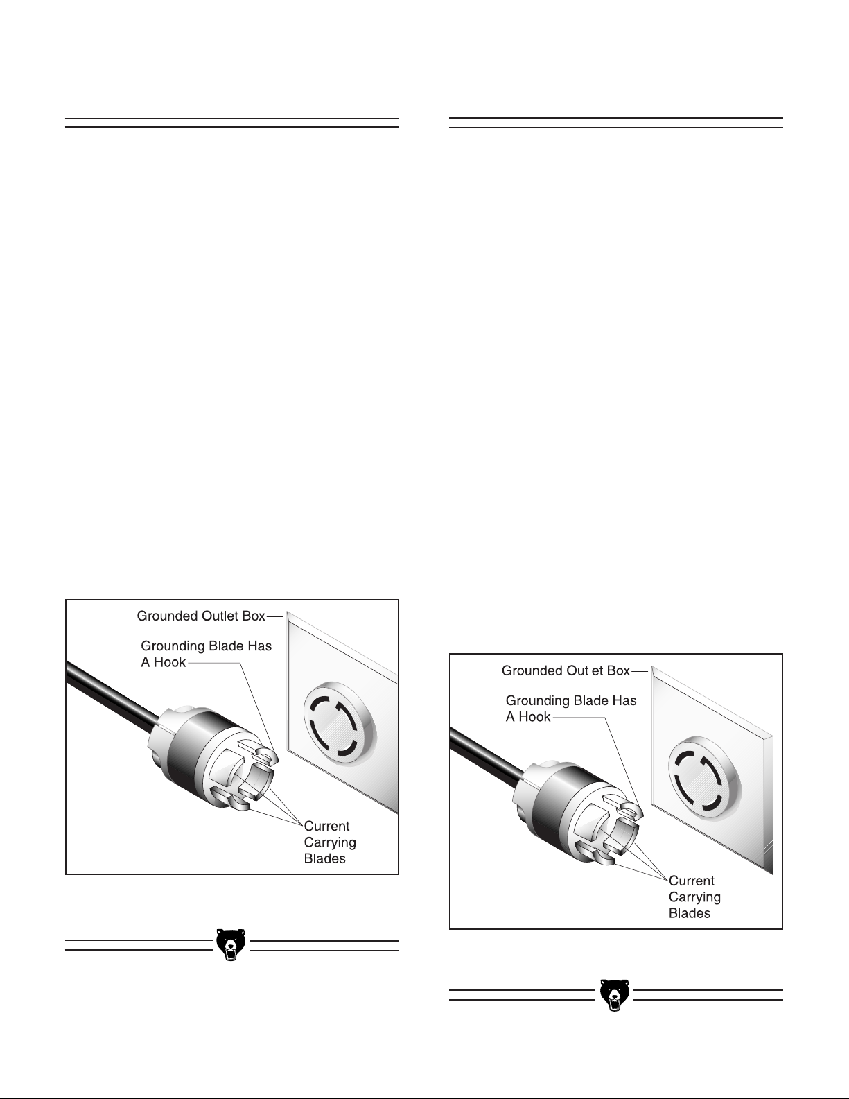
We recommend using a NEMA-style L16-20 plug
and outlet similar to that in
Figure 3. You may
also “hard-wire” the bandsaw directly to your
panel, provided you place a disconnect near the
machine. Check the electrical codes in your area
for specifics on wiring requirements.
If you convert the bandsaw to 440V, the stock
magnetic switch must be replaced with a different magnetic switch specifically for 440V
use. The 440 magnetic switch is not included
with your bandsaw.
Figure 3. Typical plug configuration for 440V,
3-phase operation.
Page 10
-8- 18" & 20" Super Heavy-Duty Bandsaws
Under no circumstances should the grounding
blade from any plug be removed. If it will not fit
the outlet, have the proper outlet installed by a
qualified electrician. Repair or replace damaged
or worn cords immediately.
Check with a qualified electrician or one of our
service personnel if the grounding instructions
are not completely understood, or if you are in
doubt as to whether the tool is properly grounded.
Use only extension cords that have grounding
type plugs and receptacles that accept the plug
on the machine
.
Grounding
In the event of a malfunction or breakdown,
grounding provides a path of least resistance for
electric current to reduce the risk of electric
shock. This tool is not supplied with an electric
cord. A cord with a plug with a grounding pin must
be wired into the junction box on the back of the
machine. Also needed is a matching outlet that is
properly installed and grounded in accordance
with all local codes and ordinances.
Improper connections of the electrical-grounding
conductor can result in risk of electric shock. The
conductor with green or green and yellow striped
insulation is the electrical grounding conductor. If
repair or replacement of the electric cord or plug
is necessary, do not connect the equipment
grounding conductor to a live terminal.
We have covered some basic electrical
requirements for the safe operation of your
bandsaw. These requirements are not necessarily comprehensive. You must be sure
that your particular electrical configuration
complies with local and state codes. Ensure
compliance by checking with your local
municipality or a licensed electrician.
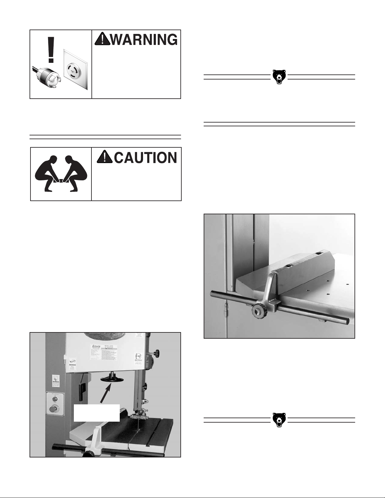
This equipment must be
grounded. Verify that any
existing electrical outlet
and circuit you intend to
plug into is actually
grounded. Under no circumstances should the
grounding pin from any
three-pronged plug be
removed. Serious injury
may occur.
We do not recommend the use of extension
cords on 220V or 440V equipment. It is much better to arrange the placement of your equipment
and the installed wiring to eliminate the need for
extension cords. Should it be necessary to use
an extension, make sure the cord is rated Hard
Service (Grade S) or better. Refer to the chart on
page 3 to determine the minimum gauge for the
extension cord. The extension cord must also
contain a ground wire and plug pin. Always repair
or replace extension cords when they become
worn or damaged.
Extension Cords
Page 11
18" & 20" Super Heavy-Duty Bandsaws -9-
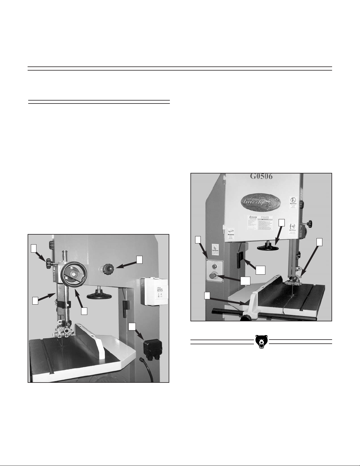
SECTION 4: CONTROLS AND
COMPONENTS
Figure 4. Rear view of bandsaw.
Identification
The 18" and 20" Super Heavy-Duty Bandsaw
controls and components are frequently referred
to in this section. Please take the time to identify
the following controls. Their locations are shown
in Figures 4 and 5:
1. Electrical Junction Box
2. Guide Post Handwheel
3. Blade Guard
4. Guide Post Lock Knob
5. Blade Tracking Handknob
Figure 5. Front view of bandsaw.
6. Upper Blade Guide Assembly
7. Fence
8. Control Panel
9. Blade Tension Handwheel
10. Emergency Stop
11. Blade Tensioning Scale
10
6
9
7
8
11
1
5
4
3
2
Page 12
-10- 18" & 20" Super Heavy-Duty Bandsaws
SECTION 5: SET UP
Piece Inventory
After all the parts have been removed from the
carton, you should have:
• Bandsaw Unit with Blade
• Table and Fence Rail
• Fence
• Dust Port
• Miter Gauge
• Hardware Bag
(4) Phillip Head Screws
(4) Hex Bolts
(4) Flat Washers
In the event that any non-proprietary parts are
missing (e.g. nuts or washers), we would be glad
to replace them, or for the sake of expediency,
replacements can be obtained at your local hardware store.
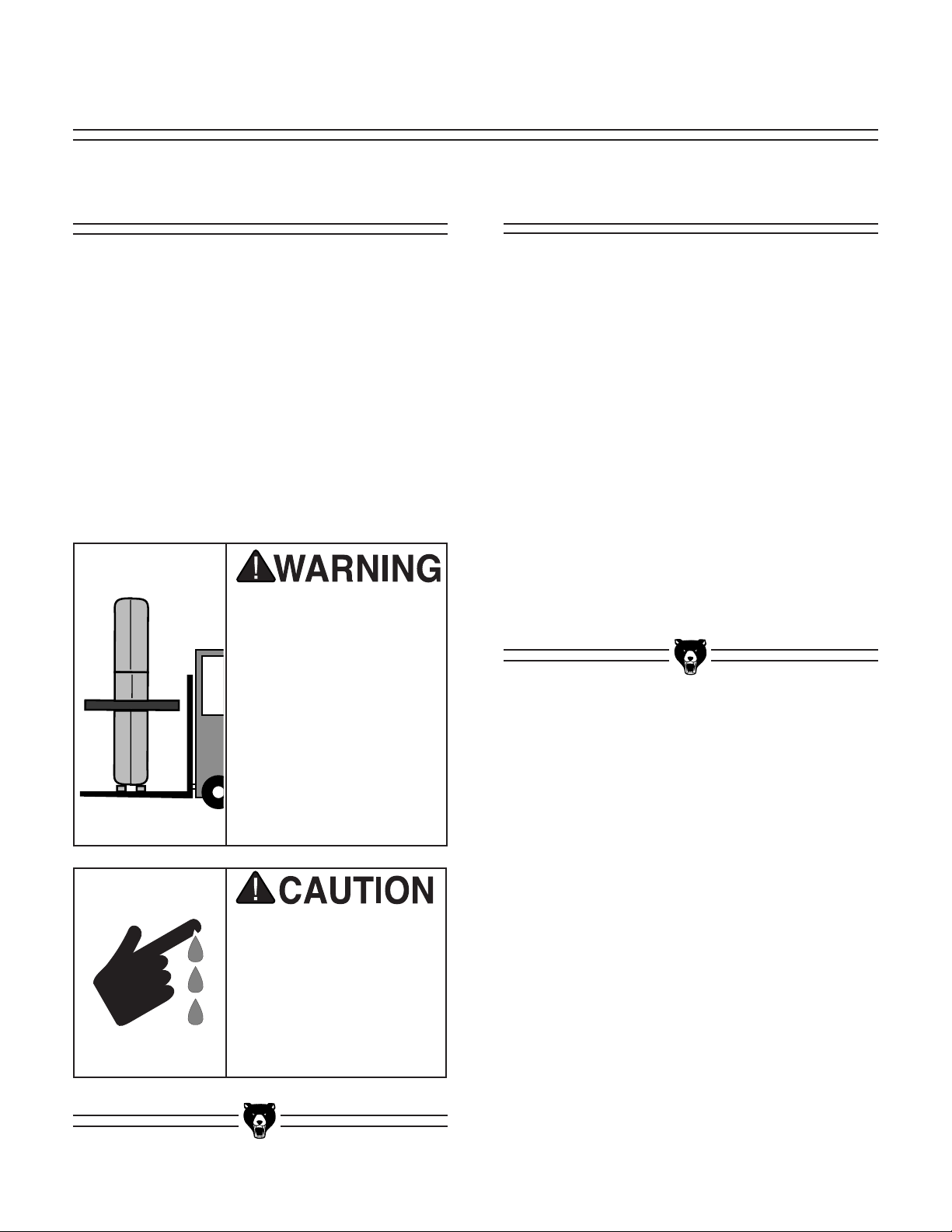
Unpacking
The 18" and 20" Super Heavy-Duty Bandsaws
are shipped from the manufacturer in a carefully
packed crate. If you discover the machine is dam-
aged after you have signed for delivery, please
call Customer Service immediately for advice.
Save the containers and all packing materials for
possible inspection by the carrier or its agent.
Otherwise filing a freight claim can be difficult.
When you are completely satisfied with the condition of your shipment, you should inventory its
parts.
Some metal parts may
have sharp edges on
them after they are
formed. Please examine
the edges of all metal
parts before handling
them. Failure to do so
could result in injury.
The 18" and 20" Super
Heavy-Duty Bandsaws
are heavy machines. DO
NOT over-exert yourself
while unpacking or
moving your machine –
you will need assistance and power equipment. Serious personal
injury may occur if safe
moving methods are not
followed.
Page 13
18" & 20" Super Heavy-Duty Bandsaws -11-
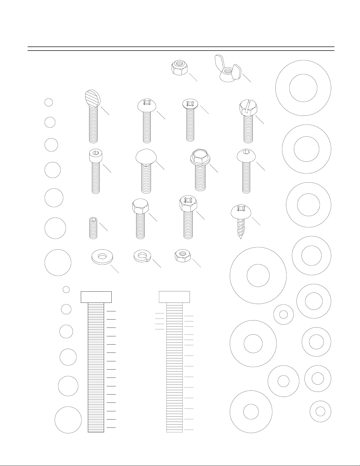
Use this chart to match up
hardware pieces during the
assembly process!
Hardware Chart
#
10
Lock
Nut
Wing
Nut
S
A
W
D
I
A
R
E
H
M
E
T
⁄8''
E
R
5
1
⁄4''
Thumb
Screw
Phillips
Head
5
⁄16''
3
⁄8''
7
Cap
Screw
⁄16''
Screw
Carriage
Bolt
Hex
1
⁄2''
Setscrew
5
⁄8''
Head
Bolt
Lock
Washer
MEASURE BOLT DIAMETER BY PLACING INSIDE CIRCLE
4mm
6mm
5mm
10mm
8mm
15mm
20mm
Washer
1
⁄4''
3
⁄8''
1
⁄2''
5
⁄8''
25mm
10mm
30mm
35mm
40mm
45mm
12mm
LINES ARE 1MM APART
50mm
55mm
60mm
⁄16'' INCH APART
1
65mm
16mm
70mm
75mm
LINES ARE
Countersunk
Phillips
Head
Screw
Flange
Bolt
Phillips
Head
Hex
Bolt
Hex
Nut
5
⁄16''
7
⁄16''
9
⁄16''
3
⁄4''
7
⁄8''
1''
11⁄4''
1
⁄2''
1
3
⁄4''
1
2
1
⁄4''
2
1
⁄2''
2
3
⁄4''
2
3
Slotted
Screw
A
S
H
W
D
I
A
R
9
⁄16''
M
E
T
E
R
E
Button
Head
D
I
A
A
H
S
W
R
E
M
E
T
⁄2''
E
R
1
Screw
Phillips
Head
Sheet
Metal
Screw
D
I
A
R
12mm
D
I
A
D
I
A
M
M
E
T
E
R
D
I
A
R
M
E
H
E
S
T
E
A
R
W
M
4mm
E
T
E
R
D
I
A
R
M
E
S
A
W
6mm
E
T
E
R
H
E
T
E
R
A
S
S
W
H
A
S
A
E
H
E
W
E
H
W
R
10mm
R
8mm
WASHERS ARE MEASURED BY THE INSIDE DIAMETER
D
I
A
R
W
H
S
A
M
E
T
7
⁄16''
E
R
D
I
R
A
M
E
W
H
S
E
3
T
⁄8''
E
R
D
I
A
R
M
E
E
5
T
⁄16''
E
A
R
W
D
I
A
R
M
E
H
E
1
S
⁄4''
T
A
E
R
W
D
I
R
A
E
M
H
E
S
T
A
E
R
W
#
10
E
H
S
A
Page 14
-12- 18" & 20" Super Heavy-Duty Bandsaws
Site Considerations
1. Floor Load: The 18" and 20" Super Heavy-
Duty Bandsaws represent a large weight
load in a small footprint. Most commercial
floors are suitable for your machine. Some
residential floors may require additional reinforcement to support both machine and
operator.
2. Working Clearances: Consider existing and
anticipated needs, size of material to be
processed through each machine, and
space for auxiliary stands, work tables or
other machinery when establishing a location for your bandsaw.
3. Lighting and Outlets: Lighting should be
bright enough to eliminate shadow and prevent eye strain. Electrical circuits should be
dedicated or large enough to handle amperage requirements. Outlets should be located
near each machine so power or extension
cords are clear of high-traffic areas. Observe
local electrical codes for proper installation
of new lighting, outlets, or circuits.
Make your shop “child safe.”
Ensure that your workplace
is inaccessible to children
by closing and locking all
entrances when you are
away. Never allow visitors in
your shop when assembling,
adjusting, or operating
equipment.
Clean Up
The unpainted surfaces are coated with a waxy
oil to protect them from corrosion during shipment. Remove this protective coating with a solvent cleaner or citrus-based degreaser such as
Grizzly’s G7895 Degreaser. To clean thoroughly,
some parts may need to be removed. For opti-
mum performance from your machine, make
sure you clean all moving parts or sliding
contact surfaces that are coated. Avoid chlo-
rine-based solvents as they may damage painted
surfaces should they come in contact. Always follow the manufacturer’s instructions when using
any type of cleaning product.
Do not use gasoline or
other petroleum-based
solvents to clean with.
They have low flash
points which make them
extremely flammable. A
risk of explosion and
burning exists if these
products are used.
Do not smoke while using
solvents. A risk of explosion or fire exists and may
result in serious personal
injury.
Many of the solvents
commonly used to clean
machinery can be toxic
when inhaled or ingested. Always work in wellventilated areas far from
potential ignition sources
when dealing with solvents. Use care when disposing of waste rags and
towels to be sure they do
not create fire or environmental hazards.
Page 15
18" & 20" Super Heavy-Duty Bandsaws -13-
Figure 6. Table installed correctly.
Table
To mount the table:
1. Installing the table is easiest if the blade is
out of the way. Remove the blade by first
loosening the blade tension handwheel,
move the blade guide bearings (refer to the
section titled Blade Changes on page 25)
then by sliding it off the bandsaw wheels.
Wear heavy leather gloves to protect your
hands.
2. With the help of another person, lift the table
onto the trunnion.
Blade Tension
Handwheel
The table for this bandsaw
is very heavy. Get help
when placing it on the
trunnion.
Fence
Figure 7. Fence mounted on rail.
To mount the fence:
1. Loosen the lock knob and slide the fence
onto the rail.
2. Slide the fence beyond the center of the
table so the blade can be installed without
blocking the fence as shown in Figure 7.
3. Please refer to the section titled Blade
Changes on page 25 to install the blade.
4. Tension the blade enough to keep it on the
saw so it does not spring off during the rest
of the assembly process.
3. Place the large hex bolt with washer through
the table trunnion mount and the trunnion.
The assembly should now look similar to
Figure 6.
DO NOT connect power
to the bandsaw until
instructed to do so.
Failure to do this may
result in serious personal injury.
Page 16
-14- 18" & 20" Super Heavy-Duty Bandsaws
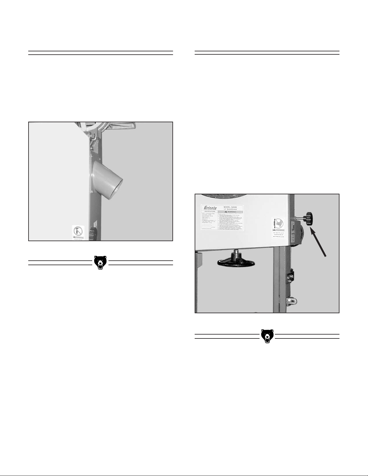
Figure 8. Dust port installed.
Dust Port
To install the dust port:
1. Place the dust port on the saw as shown in
Figure 8.
2. Secure it with the included Phillips head
screws.
Figure 9. Guide post lock knob.
Guide Post
The rack and pinion guide post can be easily
raised and lowered.
To adjust the guide post:
1. Loosen the guide post lock knob indicated by
the arrow in
Figure 9
.
2. Turn the guide post handwheel.
3. Tighten the lock knob.
Because the blade guard and the entire upper
blade guide assembly are attached to the guide
post, these items move up or down with the guide
post.
Page 17
18" & 20" Super Heavy-Duty Bandsaws -15-
The blade guard can be adjusted along the support rod to help facilitate adjustments made to the
blade guide assembly. The blade guard must
be adjusted to the lowest position on the support rod before starting the machine.
To move the blade guard:
1. Loosen the hex bolt shown in Figure 9 that
secures the blade guard bracket to the guide
post.
2. Move the blade guard up prior to making
adjustments to the guide bearing assembly,
or down, prior to using the machine.
3. Align the slot in the front of the guard with the
blade and tighten the hex bolt that secures
the it to the guide post.
Blade Guard
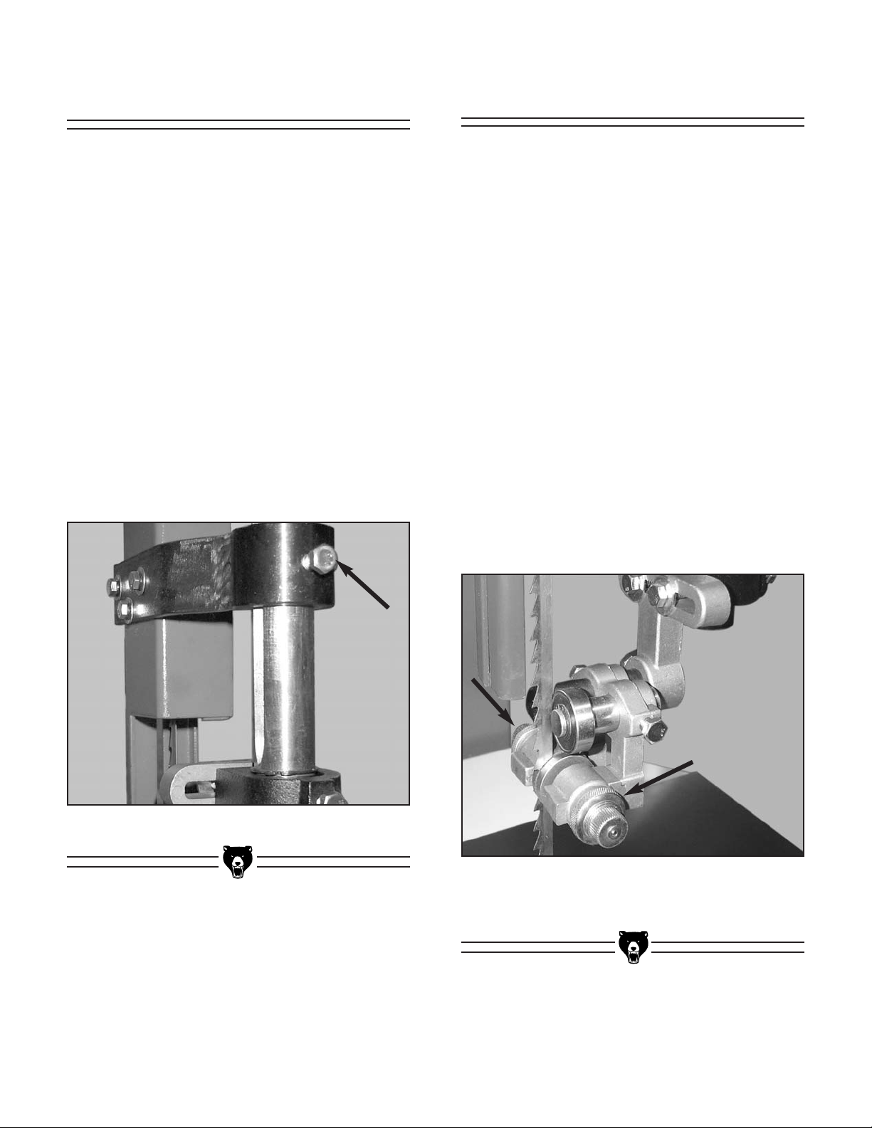
Figure 10. Blade guard mounting bracket.
Blade Guides
Always adjust the upper and lower blade guides
away from the blade before removing, installing
or tracking a new blade.
To adjust the blade guides:
1. Loosen the 4 knurled jam nuts (the upper
guide assembly is shown in Figure 11) that
lock the adjusting knob for the guide bearings in place.
2. Rotate the knurled adjuster knob counterclockwise.
3. Loosen the hex bolt for the back bearing and
slide it back. This will allow the blade to be
removed or tracked without interference.
4. After the blade tension and the blade tracking are set correctly, follow the “Guide
Bearing” and “Support Bearing” instructions
in this section for adjustment details.
Figure 11. Loosen the jam nuts on both sides of
the guide block assembly to release the blade
guide adjusting knobs.
Page 18

-16- 18" & 20" Super Heavy-Duty Bandsaws
Blade Tracking
Always adjust the blade guides away from the
blade before making blade tracking adjustments.
The wheels on the Model G0506/G0507/G0511
Super Heavy-Duty Bandsaws are crowned and
have rubber tires. This style requires center blade
tracking for proper operation.
To adjust blade tracking:
1. Open the upper wheel cover door. Slowly
rotate the upper wheel and watch where the
blade rides on the wheel. If the blade stays
centered on the crown of the wheel, then it is
properly tracked.
2. If the blade does not ride centered on the
crown of the wheel, then spin the upper
wheel by hand and adjust the tracking handknob shown in
Figure 12,
until the blade is
positioned correctly.
3. Spin the wheel approximately three more
times to ensure that the blade stays centered. Adjust and check if necessary.
4. Close the upper wheel cover door.
Figure 12. Loosen the jam nut. Turning this
handwheel clockwise will move the blade further
into the saw body.
Gullet Line
Before further adjustments can be made to the
guide assembly, the guide bearings must be set
even with the “gullet line.” This is the inside edge
of the gullets for the bandsaw teeth.
To adjust blade guides to the gullet line:
Figure 13 shows the edge of the guide bearings
set even with the gullet line. A white line (A) has
been superimposed to the photo and the blade
guard has been moved for clarity.
1. Loosen the hex bolt on the right side of the
guide assembly (B).
2. Move the assembly in or out until the edge of
the guide roller is even with the gullet. If the
back bearing interferes with this, loosen the
lock bolt (C) and slide it back.
3. Tighten the bolt for the guide assembly.
Figure 13. Adjust the guide assembly so the
guide bearings are even with the “gullet line.”
Jam Nut
A
B
C
Page 19

18" & 20" Super Heavy-Duty Bandsaws -17-
The support bearings support the back of the
blade during the sawing operation. The adjustments that can be made to the support bearings
are lateral placement and backing placement.
Make sure the guide bearings are adjusted away
from the blade before making this adjustment.
Figure 14 shows the upper support bearings.
Figure 15 shows the lower assembly. When
making adjustments to the lower bearing the
assembly will move up and down as it moves
from side-to-side.
To adjust the lateral placement:
1. Loosen the hex bolts (shown in Figures 14
& 15) that allow the assembly to move side-
to-side.
2. Shift the entire assembly so the blade intersects the face of the bearing by at least
1
⁄8".
3. Tighten the hex bolts.
Figure 14. Loosen these bolts to adjust upper
bearing assembly laterally.
Support Bearings
Figure 15. Loosen this bolt to adjust lower bear-
ing assembly laterally.
Figure 16. Back bearing just touches the back
of the blade.
To adjust the backing placement:
1. Loosen the hex bolt that secures the support
bearing shaft in place.
2. Adjust the support bearing shaft so it just
touches the back of the blade as in
Figure
16
.
3. Tighten the hex bolt.
Page 20

-18- 18" & 20" Super Heavy-Duty Bandsaws
Figure 17. Guide bearings properly adjusted.
The guide bearings ensure that the blade cannot
twist during operation. Perform the steps below
for both upper and lower guide bearings.
To adjust the guide bearings:
1. Carefully tighten the guide adjustment knobs
until the guide bearings just touch the blade
on each side as in
Figure 17
. Do not deflect
the blade while making this adjustment and
do not over-tighten!
2. Tighten each of the jam nuts.
Ideally, the guide bearings should have 1 or 2
thousandths (0.001-2") clearance from the blade
and should not pinch the blade. The blade could
become hot and deformed if excessive pressure
is applied by the guide bearings. The system
employed by this bearing assembly will give
clearance for the blade when the jam nuts are
tightened. Make sure the jam nuts are tight before
starting the machine.
Guide Bearings Table Tilt
To tilt the table:
1. Loosen the large hex bolt under the table
and in the center of the table trunnion as
shown in
Figure 18
.
2. Tilt the table to the desired angle. Use the
angle gauge for easy reference.
3. Tighten the large hex bolt in the center of the
table trunnion.
Figure 18. Loosen the bolt to tilt the table.
Angle Gauge
Bolt
Page 21

18" & 20" Super Heavy-Duty Bandsaws -19-
Figure 19. Positive stop and jam nut.
Table Stop
The positive stop under the table (see Figure 19)
allows you to repeatedly square up the table after
adjusting the table to another angle.
To adjust the positive stop:
1. Loosen the large hex bolt in the center of the
table trunnion as described in the “Table Tilt”
instructions.
Figure 20. Squaring table to blade.
2. Loosen the jam nut on the positive stop bolt
shown in
Figure 19.
3. Raise the upper blade guide assembly and
place a 6" machinist’s square on the table
against the blade as shown in Figure 20.
Notice how far out of square your table is
and approximate this distance by adjusting
the positive stop up or down. Turning the
positive stop counterclockwise will raise it
and clockwise will lower it. Adjust the positive stop so the table will stop at a 90° angle
(square) to the blade.
4. Lock the positive stop by tightening the jam
nut. Do not let the stop turn while tightening
the jam nut. Tighten the large hex bolt in the
center of the table trunnion.
5. Set the angle pointer to zero on the table tilt
gauge.
Bolt
Jam nut
Page 22

-20- 18" & 20" Super Heavy-Duty Bandsaws
Figure 21. The foot brake is located below the
dust collection port.
Foot Brake
Turn on the power supply at the main panel
and/or plug in the bandsaw. Push the START but-
ton to turn on the bandsaw. Make sure that your
hand is poised over the switch and your foot is situated so you can use the emergency foot brake
in case there is a problem. The bandsaw should
run smoothly with little or no vibration or rubbing
noises. If strange or unnatural noises are imme-
diately apparent, press the STOP button or the
foot brake. Investigate and correct before operating the machine further.
If you cannot easily locate the source of an
unusual noise or vibration, feel free to contact our
service department for help.
The Model G0506/G0507 and G0511 is supplied
with a foot brake. When used, power to the motor
is disconnected and as pressure is applied to the
pedal, friction forces the blade wheels to come to
a halt.
Test Run
The rest of the adjustments in this section
require you to start the bandsaw. Before
starting the bandsaw, make sure you have
performed the preceding assembly and
adjustment instructions, and you have read
through the rest of the manual and are
familiar with the various functions and safety issues associated with this machine.
Failure to follow this warning may result in
serious personal injury or even death!
Wear safety glasses
while testing this
machine. Failure to comply may result in serious
personal injury.
The foot brake will not stop the bandsaw
wheels and blade instantly. DO NOT
become over confident and relax your safety awareness because of the foot brake feature.
Read through this entire
manual to become familiar with the controls and
the operations of the
bandsaw before turning
it on.
Page 23

18" & 20" Super Heavy-Duty Bandsaws -21-
Figure 22. Blade tension gauge.
Blade Tension
5. Turn the bandsaw OFF. Double check the
tracking and blade guides to make sure that
they do not need to be adjusted after tensioning the blade. Reset the guide bearings
and upper blade guide assembly for height.
If the blade does not cut properly, the tension
may be incorrect. Re-adjust the tension.
After setting the tension, make a note of what the
tension gauge reads. See
Figure 22.
Use this to
go back to your tension setting during later tensioning and retensioning with
that particular
blade.
Keep in mind that blades will last longer if you
release the tension after every use. Also, new
blades will often stretch with use, and not all
blades will be exactly the same length. Use the
blade tension gauge as a guide for individual
blades.
Proper blade tension is essential to any cutting
operation on the bandsaw. Any time you change
blades or remove a blade, you must re-adjust the
tension.
To adjust the tension:
1. Adjust the upper and lower guide bearings
so the guide bearings are away from the
blade. Tighten the jam nut.
2. Lower the upper guide block assembly to the
table and tighten.
3. With moderate tension already on the blade,
turn the bandsaw ON.
4. If you see the blade start to flutter, increase
the tension until the blade stops fluttering,
then tighten the tension handle an additional
half turn.
If the blade does not flutter, decrease the
tension until it begins to flutter, then tighten it
to the point that it stops fluttering. Now tighten the tension handle an additional half turn.
Page 24

-22- 18" & 20" Super Heavy-Duty Bandsaws
Blade Lead
Sometimes the bandsaw blade will not cut
straight even when the fence and blade are parallel (see Figure 23). This condition is called
“lead.” Lead occurs (1) if the blade tension is
incorrect, (2) if the teeth are dull on one side, or
(3) if the teeth are set heavier on one side of the
blade than the other.
If you determine that your blade is causing lead
problems, you should:
• Checking/adjusting the blade tension
• Replacing the blade
• Sharpening the blade
• Skewing the fence to match the lead
• Attaching an after market or shop made
resaw fence attachment.
Fence Adjustment
The fence slides along the rail for adjustment and
can be secured in place by tightening the star
knob located on the front of the fence.
If you notice that the fence is not parallel to the
blade, adjustments can be made where the rail
mounts to the bottom of the table.
To adjust the fence so it is parallel with the
blade:
1. Get a 1" x 4" x 28" board. Joint one edge per-
fectly straight, or rip a narrow strip off the
length of the board with a table saw.
2. On the face of the board, draw a straight line
parallel to the jointed or ripped edge.
3. Slide the bandsaw fence out of the way and
cut free-hand along the line. Stop at the
halfway point. Turn the bandsaw OFF, press
the foot brake and wait for the blade to stop.
4. Clamp the board to the bandsaw table without moving it. Now slide the fence over to the
board so it barely touches one end of the
board.
5. Loosen the two hex bolts that secure the
fence rail to the underside of the table.
6. Skew the fence left or right so it is parallel to
the edge of the scrap piece. You may need
to re-adjust the fence locking mechanisms to
gain maximum adjustment.
7. While maintaining the skew, tighten the rail
mounting bolts.
8. Make a few cuts using the fence. If the fence
still does not seem parallel to the blade, read
the “Blade Lead” instructions, or repeat
steps 1-7 until the blade and fence are parallel with each other.
Figure 23. Typical example of blade leading
away from line of cut.
Page 25

18" & 20" Super Heavy-Duty Bandsaws -23-
Using this machine produces sawdust which may
cause allergic reactions
and respiratory problems.
Use an approved dust
mask to protect yourself
from dust hazards!
SECTION 6: OPERATIONS
Keep loose clothing
rolled up and out of the
way of machinery and
keep hair pulled back.
Wear safety glasses during the entire operation
process. Failure to comply may result in serious
personal injury.
Disconnect power to the
machine when performing any maintenance or
adjustments. Failure to
do this may result in serious personal injury.
Blade Selections
WE STRONGLY RECOMMEND that you read
books, trade magazines, or get formal training to maximize the potential of your
machine. The following section was
designed to give instructions on the basic
operations of this bandsaw. However, it is in
no way comprehensive of every bandsaw
application. There are many different jigs
that can be built to increase safety, accuracy, and types of cuts.
Selecting the right blade requires a combination
of the various blade characteristics mentioned
below, the type of material you plan to cut, and
the type of cut you are going to perform.
Blade Length
Measured by the circumference, blade lengths
are usually unique to the model of your bandsaw
and the wheel diameter. The Model G0506 is
designed for blades that are 147
5
⁄8"-1495⁄8" long.
The Model G0507/G0511 requires blades that
are 160
13
⁄16"-1623⁄8" long.
Blade Width
Measured from the the back of the blade to the tip
of the blade tooth (the widest point), blade width
is often the first consideration given to blade
selection.
A narrow blade can cut tight curves (a small
radius) but is not very good at cutting straight
lines, because they naturally wander (blade
lead). However, larger blades are much better at
cutting straight lines and this makes them a natural choice for resaw applications
The 18" & 20" Super Heavy-Duty Bandsaws function best with blades that are
3
⁄8" - 1" wide. Refer
to the current Grizzly catalog for prices and ordering information. Always pick the size of blade that
best suits your application.
Tooth Style
When selecting blades, another option to consider is the shape, gullet size and angle of the
teeth—otherwise known as “Tooth Style.”
Page 26

-24- 18" & 20" Super Heavy-Duty Bandsaws
Figure 24. Raker, Skip and Hook blades.
Raker
Skip
Hook
• RAKER — This style is considered to be the
standard because the tooth size and shape
are the same as the tooth gullet. The teeth
on Raker blades are usually very numerous,
have no angle, and produce cuts by scraping
the material; these characteristics result in
very smooth cuts, but at the same time do
not cut fast and generate more heat while
cutting.These blades also work well for cutting curves.
• SKIP — This style is like a raker blade that is
missing every other tooth. Because of the
design, skip toothed blades have a much
larger gullet than raker blades, and therefore, cut faster and generate less heat.
However, these blades also leave a rougher
cut than raker blades. Great for super
Heavy-Duty and ripping thin stock.
• HOOK — The teeth on this style have a positive angle (downward) which makes them
dig into the material, and the gullets are usually rounded for easier waste removal.
These blades are excellent for the tough
demands of resawing and ripping thick
stock.
Tooth Pitch
Usually measured as T.P.I. (teeth per inch), tooth
pitch determines the size of the teeth. More teeth
per inch (fine pitch) will cut slower, but smoother;
while fewer teeth per inch (coarse pitch) will cut
faster, but rougher. As a general rule, choose
blades that will have at least three, but not more
than twelve teeth in the material at all times. Use
fine pitched blades on harder woods and coarse
pitched blades on softer woods.
Blade Care
A bandsaw blade is a delicate piece of steel that
is subjected to tremendous strain. You can obtain
longer use from a bandsaw blade if you give it fair
treatment and always use the appropriate feed
rate for your operation.
Be sure to select blades with the proper width,
style, and pitch for each application. The wrong
choice of blades will often produce unnecessary
heat which will shorten the life of your blade.
A clean blade will perform much better than a
dirty blade. A dirty blade passes through the cutting material with much more resistance than a
clean blade. This extra resistance will also cause
unnecessary heat. Maintain your blades with a
cutting blade lubricant like SLIPIT
®
(Model
G5562/3 in the Grizzly Catalog).
Blade Breakage
Many conditions may cause a bandsaw blade to
break. Blade breakage is unavoidable, in some
cases, since it is the natural result of the peculiar
stresses that bandsaw blades are subjected to.
Blade breakage is also due to avoidable circumstances. Avoidable breakage is most often the
result of poor care or judgement on the part of the
operator when mounting or adjusting the blade or
support guides.
The most common causes of blade breakage are:
(1) faulty alignment or adjustment of the guides,
(2) forcing or twisting a wide blade around a curve
of short radius, (3) feeding too fast, (4) tooth dullness or absence of sufficient set, (5) excessive
tension, (6) top blade guide assembly set too high
above the work piece, (7) using a blade with a
lumpy or improperly finished braze or weld and
(8) running the bandsaw when not in use.
Figure 24 shows the three main categories of
tooth style.
Page 27

18" & 20" Super Heavy-Duty Bandsaws -25-
Figure 25. Loosen this bolt to remove assembly.
Blade Changes
To remove the blade:
1. Disconnect power to the bandsaw!
2. Release the tension on the blade by turning
the tension control knob counterclockwise.
3. Remove the upper guide assembly from the
support bar by loosening the hex bolt shown
in
Figure 25
.
4. Adjust the lower guide bearings away from
the blade.
5. Put on leather gloves to protect your hands
from the sharp teeth of the blade.
Caution—the blades are sharp!
6. Open the upper and lower wheel covers and
slide the blade off both wheels.
Wear gloves and safety goggles when handling blades. Coiled blades spring open as
they are uncoiled and could cause deep
cuts or lacerations.
Always disconnect
power to the machine
when changing blades.
Failure to do this may
result in serious personal injury.
To replace the blade:
1. Put on leather gloves to protect your hands
from the sharp teeth of the blade.
2. Slide the blade through the table slot, ensuring that the teeth are pointing down toward
the table.
If the teeth will not point downward on the
right hand side, the blade is inside-out.
Remove the blade, and twist it right side-out.
3. Slip the blade through the lower guides, and
mount it over the upper and lower wheels so
the blade is centered on the wheels.
4. Mount the upper guides by sliding the blade
between the guide bearings and then guide
the bearing bracket onto the guide post. Use
care when aligning the guide assembly so
that it does not twist the blade.
5. Apply tension, then check and adjust tracking as described in the section titled Blade
Tracking.
6. Adjust the upper and lower guide blocks and
support bearings.
7. Close and latch the wheel covers.
Page 28

-26- 18" & 20" Super Heavy-Duty Bandsaws
Ripping is the process of cutting a wide board into
two or more narrower boards. The maximum
board width that can be ripped is limited by the
maximum throat dimension of the bandsaw.
For ripping, a wider blade is better. In most ripping applications, a standard raker tooth style will
be sufficient. Also, since most ripped lumber will
be jointed smooth, you can choose blades with
fewer teeth-per-inch.
To perform ripping operations:
1. The bandsaw must be adjusted correctly.
See “Blade Tension/Tracking” instructions
and “Fence Adjustment” instructions.
2. Adjust the blade guard so it is just above the
workpiece with a minimum amount of blade
exposed. Read instructions on “Blade Lead”
before making a cut.
3. Use a fence to guide the work. Set the distance between the fence and the blade to the
desired width.
4. Support the ends of the board if necessary.
5. Feed the work slowly and evenly with the
straightest edge against the fence.
Ripping Stacked Cuts
One of the benefits of a bandsaw is its ability to
cut multiple copies of a particular shape by stacking a number of workpieces together.
Before making stacked cuts, it is essential to
ensure that both the table and the blade are properly adjusted to 90°. Otherwise, any error will be
compounded with each piece from the top to the
bottom of the stack.
To complete a stacked cut:
1. Align your pieces from top to bottom to
ensure that each piece has adequate scrap
to provide a clean, unhampered cut.
2. Secure all the pieces together using brad
nails through the waste portion or using
beads of hot glue across the outside edges.
3. Lay out the shape you intend to cut on the
face of the top piece.
4. Adjust the blade guard so it is just above the
workpiece with a minimum amount of the
blade exposed. One inch is ideal.
5. Make relief cuts perpendicular to the outline
of your intended shape in areas where
changes in blade direction could strain the
blade.
6. Cut the stack of pieces as though you were
cutting a single piece. Follow the layout line
with the blade kerf on the waste side of your
line.
Page 29

18" & 20" Super Heavy-Duty Bandsaws -27-
Resawing
Resawing is the process of cutting the thickness
of a board into two or more thinner boards. Each
new board is the same width and length as the
original board, but the thickness is less. The maximum board width that can be resawn is limited by
the maximum cutting height of the bandsaw.
The most important consideration when resawing
is blade selection. When selecting a blade, keep
in mind that generally a wider blade makes cutting a straight line easier.
In most applications a hook or skip tooth style will
work best. Also, since most resawn lumber will be
planed smooth, you can choose blades with
fewer teeth per inch (3 to 6). While blades with
fewer teeth per inch produce rougher cuts, these
types of blades offer larger gullet capacities for
clearing sawdust, they produce less heat, and
they yield more horsepower per tooth.
To resaw lumber, follow the procedure below:
1. The blade must be adjusted correctly for ten-
sion and tracking.
2. The fence must be parallel to the blade.
3. Adjust the upper blade guide so it is just
above the workpiece with a minimum
amount of blade exposed.
4. Use the widest blade that will fit your bandsaw. (Your saw has a 1" width capacity). The
blade must also be sharp and in good condition. Read “Blade Lead” instructions.
5. Use the fence to guide the work.
6. Support the weight of the board with infeed
and/or outfeed rollers, if necessary.
7. Feed the work slowly and evenly.
When resawing, consider using an auxiliary fence
that is higher than the standard fence. This provides a more solid surface for the workpiece to
slide against. An auxiliary fence can be made
from any straight and flat piece of lumber and can
be bolted or screwed to the standard fence.
When using a fence to guide the board, the actual line of cut may not be exactly parallel to the
fence. This is due to a number of reasons involving the configuration of the table, condition of the
blade, the cutting forces, and the blade tension.
To correct this condition, refer to the “Blade Lead”
instructions.
Do not force the wood into the blade during
cutting. This will distort the blade, cause
excessive heat and often results in blade
breakage. Breakage can cause abrasions,
cuts, or serious personal injury.
Page 30

-28- 18" & 20" Super Heavy-Duty Bandsaws
SECTION 7: MAINTENANCE
V-Belts
To ensure optimum power transmission from the
motor to the blade, the V-belt must be in good
condition and operate under proper tension. The
belt should be checked for cracks, fraying and
wear. Belt tension should be checked at least
every 3 months; more often if the bandsaw is
used daily.
To adjust the V-belt:
1. The V-belt is accessed via the bottom cover.
2. Squeeze the center of the V-belt.
3. Note the amount of deflection.
4. Deflection should be approximately
3
⁄4".
5. Loosen the bolts which secure the motor
support bracket to the back of the bandsaw
and pull the motor and bracket up.
6. Tighten the bolts and recheck the tension.
7. Make further adjustments if needed until the
belt deflects
3
⁄4".
The table and other non-painted surfaces on the
18" and 20" Super Heavy-Duty Bandsaws should
be protected against rust and pitting. Wiping the
saw clean after every use ensures that wood dust
is not allowed to trap moisture against bare metal
surfaces.
To keep table rust free:
1. Use regular applications of products like
SLIPIT
®
.
2. For long term storage consider using products like Boeshield
®
T-9. See the current
Grizzly catalog for complete list of these
products.
Table
Always be aware of the condition of your bandsaw. Routinely check the condition of the following items and repair or replace as necessary:
• Loose mounting bolts
• Worn switch
• Worn or damaged blade
• Worn or damaged support bearings or guide
bearings
Miscellaneous
Always disconnect
power to the machine
when performing maintenance. Failure to do this
may result in serious
personal injury.
Page 31

18" & 20" Super Heavy-Duty Bandsaws -29-
The sealed and pre-lubricated ball bearings on
most of the moving parts of this bandsaw require
no lubrication for the life of the bearings. These
bearings are standard sizes, and replacements
can be purchased from our parts department or a
bearing supply store.
The guide bearings do require oil daily or after
every 8 hours of use. They are supplied with a
detent ball valve for an oiling port and can be
oiled with a “squirt-gun” type oiler. We recommend 10 wt. non-detergent oil.
To oil the guide bearings:
1. Clean all the oiling ports with a paper towel
or a clean rag.
2. Press the tip of the oiler against the ball as
shown in Figure 23.
3. Apply only a small amount of oil. Excess oil
can spread to the blade and contaminate the
workpiece and bandsaw wheels.
4. Wipe off excess oil from around the oiling
port.
Lubrication
The bandsaw is supplied with a lower wheel
brush. This may need occasional cleaning and
adjustment. It is advisable to check it once a day
and make sure that it is clear of dust and any
small bits of wood that may have become trapped
between it and the lower wheel. The mounting
bracket that secures it to the bandsaw body is
slotted for adjustments as the bristles become
worn. Please contact our parts department
should replacement become necessary.
Wheel Brush
Figure 26. Oiling an upper blade guide bearing.
As for other items on this machine:
1. Wipe off any sawdust with a clean cloth or
dry paint brush on and around the guide post
assembly.
2. Lubricate the guide post assembly with an
occasional “shot” of spray on lubricant.
Ensure that oil does not get on the pulleys or Vbelt because it could cause belt deterioration and
slipping.
Page 32

-30- 18" & 20" Super Heavy-Duty Bandsaws
A1
G0506 &G0507
Wiring Diagram
GROUND
A2
1
2
16
1
8
GROUND
Page 33

18" & 20" Super Heavy-Duty Bandsaws -31-
THREE-PHASE
220 VOLT POWER SOURCE
A1
A2
G0511
Wiring Diagram
GROUND
1
2
U1 U5 V1 V5 W1 W5
U2—V2—W2
16
1
8
GROUND
GROUND
V1 W1
U1
U2U5V2V5W2
W5
440 VOLT WIRING
220 VOLT WIRING
Page 34

-32- 18" & 20" Super Heavy-Duty Bandsaws
The following pages contain general machine
data, parts diagrams/lists, troubleshooting guide
and Warranty/Return information for your 18" and
20" Super Heavy-Duty Bandsaws.
If you need parts or help in assembling your
machine, or if you need operational information,
we encourage you to call our Service
Department. Our trained service technicians will
be glad to help you.
If you have comments dealing specifically with
this manual, please write to our Bellingham,
Washington location using the address in the
General Information section. The specifications,
drawings, and photographs illustrated in this
manual represent the 18" and 20" Super HeavyDuty Bandsaws as supplied when the manual
was prepared. However, due to Grizzly’s policy of
continuous improvement, changes may be made
at any time with no obligation on the part of
Grizzly.
We have included some important safety measures that are essential to the operation of this
machine. While most safety measures are generally universal, Grizzly reminds you that each
workshop is different and safety rules should be
considered
as they apply to your specific situa-
tion.
We recommend you keep a copy of our current
catalog for complete information regarding
Grizzly's warranty and return policy. If you need
additional technical information relating to your
machine, or if you need general assistance or
replacement parts, please contact the Service
Department listed in the General Information sec-
tion.
Additional information sources are necessary to
realize the full potential of your machine. Trade
journals, woodworking magazines, and your local
library are good places to start.
SECTION 8: CLOSURE
Like all power tools, there is danger associated with the 18" and 20" Super Heavy-Duty
Bandsaws. Use your bandsaw with respect
and caution to lessen the possibility of
mechanical damage or operator injury. If
normal safety precautions are overlooked
or ignored, serious personal injury may
occur.
The 18" and 20" Super Heavy-Duty
Bandsaws were specifically designed for
wood cutting operations. DO NOT MODIFY
AND/OR USE THESE BANDSAWS FOR ANY
OTHER PURPOSE. Modifications or improper use will void the warranty. If you are confused about any aspect of your machine, DO
NOT use it until all your questions are
answered. Serious personal injury may
occur.
Operating this equipment has the potential
for flying debris to cause eye injury. Always
wear safety glasses or goggles when operating equipment. Everyday glasses or reading glasses only have impact resistant lenses, they are not safety glasses. Be certain
the safety glasses you wear meet the appropriate standards of the American National
Standards Institute (ANSI).
Page 35

18" & 20" Super Heavy-Duty Bandsaws -33-
Customer Service #: (570) 546-9663 • To Order Call: (800) 523-4777 • Fax #: (800) 438-5901
MACHINE DATA
SHEET
Design Type...................................................................................................... Floor Model
Overall Dimensions:
Table Size ..................................................................................24"W x 19
3
⁄4"D x 17⁄8"T
Height From Floor To Table ..................................................................................35
3
⁄4"
Overall Height ..........................................................................................................72"
Overall Width ............................................................................................................32"
Overall Depth (Including Fence)............................................................................29
1
⁄2"
Shipping Weight ................................................................................................616 lbs.
Machine Weight ................................................................................................462 lbs.
Crate Size ................................................................................76
3
⁄4"H x 26"W x 361⁄4"L
Footprint..................................................................................................26
3
⁄4"W x 15"L
Capacities:
Throat Capacity (Left of Blade) ................................................................................17"
Height Capacity ......................................................................................................9
3
⁄4"
Table Tilt ................................................................................................................45˚R
Blade Size Range ................................................................................................
3
⁄8"~1"
Standard Blade Length ............................................................................147
5
⁄8"-1495⁄8"
Blade Speed..................................................................................................4610 FPM
Construction:
Table ..................................................................................Precision Ground Cast Iron
Wheels ................................................Fully Balanced Cast Iron w/Polyurethane Tires
Rip Fence ..........................................................................Precision Ground Cast Iron
Wheel Covers....................................................................................Pre-Formed Steel
Guides........................................................................Sturdy Roller Disc Blade Guides
Main Motor:
Type ............................................................................TEFC Capacitor-Start Induction
Horsepower............................................................................................................2 HP
Phase ⁄ Voltage ............................................................................Single-Phase ⁄ 220V
Amps ......................................................................................................................12A
Cycle ⁄ RPM..................................................................................60 Hertz ⁄ 1725 RPM
Switch ............................................................Magnetic w/Thermal Overload Protector
Bearings ..............................................................Shielded & Lubricated Ball Bearings
Features:
..................................................................................................................4" Dust Hood
....................................................................................................................Foot Brake
................................................................................................Blade Tensioning Scale
..................................................................................................................Miter Gauge
........................................................................Rack & Pinion Adjustable Upper Guide
....................................................................................................Hinged Wheel Covers
Specifications, while deemed accurate, are not guaranteed.
MODEL G0506 18" SUPER HEAVY-DUTY BANDSAW
Page 36

-34- 18" & 20" Super Heavy-Duty Bandsaws
G0506
Page 37

18" & 20" Super Heavy-Duty Bandsaws -35-
G0506
60
61
62
Page 38

-36- 18" & 20" Super Heavy-Duty Bandsaws
G0506
Page 39

18" & 20" Super Heavy-Duty Bandsaws -37-
G0506
Page 40

-38- 18" & 20" Super Heavy-Duty Bandsaws
G0506
60
61
62
Page 41

18" & 20" Super Heavy-Duty Bandsaws -39-
REF PART # DESCRIPTIONREF PART # DESCRIPTION
052 PB21 HEX BOLT 3⁄8"-16 X 3⁄4"
053 P0506053 STOP SWITCH
054 PSB21M CAP SCREW M4-.7 X 30
055 P0506055 UPPER WHEEL
056 P0506056 UPPER WHEEL SHAFT
057 P6205 BEARING 6205Z
058 P0506058 IN BUSHING
059 P0506059 OUT BUSHING
060 P0506060 INT SNAP RING 52MM
061 PW021 FLAT WASHER
3
⁄8"
062 PB03 HEX BOLT
3
⁄8"-16 X 1"
063 P0506063 RUBBER CROWN
064 P0506064 LOWER WHEEL
065 P0506065 LOWER WHEEL SHAFT
066 P0506066 BRUSH BRACKET
067 P0506067 BRUSH
068 PB03 HEX BOLT
5
⁄16"-18 X 1"
069 PW07 FLAT WASHER
5
⁄16"
070 PN02 HEX NUT
5
⁄16"-18
071 P0506071 SPECIAL WASHER
3
⁄8"~2"
072 PB24 HEX BOLT
3
⁄8"-16 X 11⁄4"
073 PB24 HEX BOLT
3
⁄8"-16 X 11⁄4"
074 PN08 HEX NUT
3
⁄8"-16
075 P0506075 ARBOR BRACKET
076 PB24 HEX BOLT
3
⁄8"-16 X 11⁄4"
077 PN08 HEX NUT
3
⁄8"-16
078 P0506078 BLADE TENSION SHAFT
079 P51104 THRUST BEARING 51104
082 P0506082 INDICATOR WIRE PULLER
083 P0506083 SPRING
084 P0506084 BRACKET HOLDER
085 PN08 HEX NUT
3
⁄8"-16
086 PW02 FLAT WASHER
3
⁄8"
087 P0506087 BRACKET SHAFT
088 PN08 HEX NUT
3
⁄8"-16
089 P0506089 TENSION HANDWHEEL
090 PSS08 SETSCREW
5
⁄16"-18 X 1⁄2"
091 P0506091 TABLE
092 P0506092 FENCE RAIL
093 PB18 HEX BOLT
3
⁄8"-16 X 1"
094 PW02 FLAT WASHER
3
⁄8"
095 P0506095 FENCE
096 P0506096 FENCE KNOB
3
⁄8"-16 X 11⁄4"
097 P0506097 TRUNNION
098 PSB19 CAP SCREW
3
⁄8"-16 X 11⁄4"
099 PLW04 LOCK WASHER
3
⁄8"
100 P0506100 HEX BOLT
1
⁄2"-12 X 13⁄4"
101 PW01 FLAT WASHER
1
⁄2"
001 P0506001 FRAME
002 P0506002 HINGE
003 P0506003 UPPER WHEEL GUARD
004 P0506004 LOWER WHEEL GUARD
005 PSB17 CAP SCREW
1
⁄4"-20 X 3⁄8"
006 P0506006 WHEEL GUARD LOCK KNOB
007 PSB05 CAP SCREW
1
⁄4"-20 X 3⁄4"
008 PN05 HEX NUT
1
⁄4"
009 P0506009 1-PH 2 HP MOTOR
09-1 P0506009-1 CAPACITOR 400MFD-125V
010 PK43M KEY 8 X 8 X 45
011 P0506011 MOTOR PULLEY
012 PSS08 SETSCREW
5
⁄16"-18 X 1⁄2"
013 P0506013 MOTOR FLANGE
014 P0506014 ADJUSTING SCREW
3
⁄8"-16
015 PN08 HEX NUT
3
⁄8"-16
017 PW02 FLAT WASHER
3
⁄8"
018 PLW04 LOCK WASHER
3
⁄8"
023 PVA37 V-BELT A37
024 P0506024 DUST BOARD
025 P0506025 WOOD BOARD
026 PB03 HEX BOLT
5
⁄16"-18 X 1"
027 PW07 FLAT WASHER
5
⁄16"
028 PN02 HEX NUT
5
⁄16"
029 PS06 HEX BOLT 10-24 X
3
⁄8"
030 P0506030 CHIP CHUTE
031 PS06 PHLP HD SCR 10-24 X
3
⁄8"
032 P0506032 BLADE TENSION INDICATOR
033 PSB04 CAP SCREW
1
⁄4"-20 X 1⁄2"
034 P0506034 WIRE BRACKET
035 PS06 PHLP HD SCR 10-24 X
3
⁄8"
036 PB58 HEX BOLT
3
⁄8"-16 X 2"
037 PN08 HEX NUT
3
⁄8"-16
038 P0506038 1-PH MAG SWITCH
38-1 P0506038-1
CONTACTOR/THERMAL OVRLD
039 P0506039 ON SWITCH (GREEN)
040 P0506040 OFF SWITCH (RED)
041 P0506041 POWER CONTROL PANEL
042 PS06 PHLP HD SCR 10-24 X
3
⁄8"
043 P0506043 CONNECTION PLATE
044 P0506044 BRAKE LINING
045 PB18 HEX BOLT
3
⁄8"-16 X 1"
046 PB19 HEX BOLT
1
⁄4"-20 X 1⁄2"
047 P0506047 FOOT BRAKE PEDAL
048 PLW04 LOCK WASHER
3
⁄8"
049 PN08 HEX NUT
3
⁄8"-16
050 P0506050 SPRING
051 PN08 HEX NUT
3
⁄8"-16
G0506
Page 42

-40- 18" & 20" Super Heavy-Duty Bandsaws
REF PART # DESCRIPTION REF PART # DESCRIPTION
102 P0506102 TRUNNION BRACKET
103 P0506100 HEX BOLT
1
⁄2"-12 X 13⁄4"
104 PLW07 LOCK WASHER
1
⁄2"
105 P0506105 BLADE GUIDE FORK
106 PB07 HEX BOLT
5
⁄16"-18 X 3⁄4"
107 PW02 FLAT WASHER
3
⁄8"
108 P0506108 SHAFT CAP
109 PB03 HEX BOLT
5
⁄16"-18 X 1"
110 PLW01 LOCK WASHER
5
⁄16"
111 P0506111 LOCK KNOB
3
⁄8"-16 X 21⁄4"
112 P0506112 GUIDE SHAFT
113 P0506113 C-CLIP
114 P0506114 ELEVATION GEAR SHAFT
115 P0506115 GEAR SHAFT BASE
116 PB03 HEX BOLT
5
⁄16"-18 X 1"
117 PLW01 LOCK WASHER
5
⁄16"
118 P0506118 HANDWHEEL
119 P0506119 SPRING KEY M4
120 P0506120 TRACK KNOB
3
⁄8"-16 X 21⁄2"
121 PN08 HEX NUT
3
⁄8"-16
122 P0506122 BLADE GUIDE GUARD
123 P0506123 BLADE GUARD BRACKET
124 PB19 HEX BOLT
1
⁄4"-20 X 1⁄2"
125 PLW02 LOCK WASHER
1
⁄4"
126 PW06 FLAT WASHER
1
⁄4"
127 P0506127 BLADE GUIDE HOLDER
128 PB03 HEX BOLT
5
⁄16"-18 X 1"
129 PW07 FLAT WASHER
5
⁄16"
130 PB07 HEX BOLT
5
⁄16"-18 X 3⁄4"
131 P0506131 ADJUSTMENT BRACKET
132 P0506132 BRACKET ARBOR
133 P0506133 BLADE GUIDE BASE
134 PSB07 CAP SCREW
5
⁄16"-18 X 3⁄4"
135 P0506135 GUIDE WHEEL BRACKET
136 P0506136 GUIDE WHEEL
137 P0506137 GUIDE WHEEL NUT
140A
P0506140A COMPLETE MITER GAUGE
140 P0506140 MITER GAUGE BODY
141 P0506141 T-SLOT WASHER
142 PFH09 FLAT HD SCR
1
⁄4"-20 X 5⁄16"
143 P0506142 MITER BAR
144 P0506144 SPECIAL BOLT
1
⁄4"-20 X 7⁄16"
145 P0506145 STOP PIN
146 P0506146 BLOCK
147 P0506147 INDICATOR
148 PS29 PHLP HD SCR 6-32 X
5
⁄8"
149 PS06 PHLP HD SCR 10-24 X
3
⁄8"
150 P0506150 HANDLE
5
⁄16"-18 X 11⁄2"
151 PW07 FLAT WASHER
5
⁄16"
152 PN12 HEX NUT 6-32
160 G8589 LARGE GRIZZLY LOGO
161 P05060161 SELF TAP SCR #5 X
3
⁄8"
162 P05060162 G0506 ID LABEL
163 PLABEL-14 ELECTRICITY LABEL
164 PLABEL-18 UNPLUG BANDSAW LABEL
165 PLABEL-19 HANDS/BLADE LABEL
166 PLABEL-20 DON’T OPEN LABEL
167 PLABEL-12 READ MANUAL LABEL
168 PLABEL-11 SAFETY GLASSES LABEL
169 PLABEL-20 MOVING/ADJUST LABEL
174 P0506174 THRUST BEARING SHAFT
175 P6202RS BALL BEARING 6202
176 PEC05M E-CLIP 15MM
177 P0506177 CABLE CLIP
178 P0506178 CABLE NUT 6-32
179 PS37 PHLP HD SCR 6-32 X
5
⁄16"
180 PS06 PHLP HD SCR 10-24 X
3
⁄8"
181 P0506181 TERMINAL BLOCK
182 P0506182 STUD 10-24 X 2
1
⁄2"
183 PN07 HEX NUT 10-24
184 PW03 FLAT WASHER 10-24
185 PSW10 STRAIN RELIEF
3
⁄4"
186 P0506186 COVER
188 PHTEK5 SELF TAP SCR 10-24 X 2
1
⁄4"
189 P0506189 POWER CORD
G0506
Page 43

18" & 20" Super Heavy-Duty Bandsaws -41-
Customer Service #: (570) 546-9663 • To Order Call: (800) 523-4777 • Fax #: (800) 438-5901
MACHINE DATA
SHEET
Design Type ......................................................................................................Floor Model
Overall Dimensions:
Table Size ....................................................................................................27" x 20
1
⁄2"
Overall Height ..........................................................................................................76"
Height From Floor to Table ..................................................................................36
1
⁄4"
Width ........................................................................................................................37"
Depth Including Fence ..........................................................................................29
1
⁄2"
Shipping Weight ................................................................................................748 lbs
Machine Weight ................................................................................................625 lbs
Crate Size..........................................................................80
11
⁄16"L x 279⁄16"W x 393⁄8"H
Footprint ....................................................................................................30
1
⁄2" x 151⁄2"
Capacities:
Throat Capacity (Left of Blade) ................................................................................19"
Cutting Height Capacity ........................................................................................11
1
⁄2"
Table Tilt ................................................................................................................45˚R
Blade Size Range ................................................................................................
3
⁄8"~1"
Standard Blade Length ..........................................................................160
13
⁄16"-1623⁄8"
Blade Speed..................................................................................................4510 FPM
Construction:
Table ..................................................................................Precision Ground Cast Iron
Wheels ................................................Fully Balanced Cast Iron w/Polyurethane Tires
Rip Fence ..........................................................................Precision Ground Cast Iron
Wheel Covers....................................................................................Pre-Formed Steel
Guides........................................................................Sturdy Roller Disc Blade Guides
Motor:
Type (G0507) ..............................................................TEFC Capacitor-Start Induction
Horsepower............................................................................................................3 HP
Phase ⁄ Voltage ............................................................................Single-Phase ⁄ 220V
Amps ......................................................................................................................23A
Type (G0511)........................................................................................TEFC Induction
Horsepower............................................................................................................5 HP
Phase ⁄ Voltage ....................................................................Three-Phase ⁄ 220V/440V
Amps ................................................................................................................13A/6.5
Cycle ⁄ RPM..................................................................................60 Hertz ⁄ 3450 RPM
Switch ............................................................Magnetic w/Thermal Overload Protector
Bearings ..............................................................Shielded & Lubricated Ball Bearings
Features:
..................................................................................................................4" Dust Hood
....................................................................................................................Foot Brake
................................................................................................Blade Tensioning Scale
..................................................................................................................Miter Gauge
........................................................................Rack & Pinion Upper Guide Adjustment
....................................................................................................Hinged Wheel Covers
Specifications, while deemed accurate, are not guaranteed.
MODEL G0507 & G0511
20" SUPER HEAVY-DUTY BANDSAWS
Page 44

-42- 18" & 20" Super Heavy-Duty Bandsaws
G0507/G0511
Page 45

18" & 20" Super Heavy-Duty Bandsaws -43-
G0507/G0511
60
61
62
Page 46

-44- 18" & 20" Super Heavy-Duty Bandsaws
G0507/G0511
Page 47

18" & 20" Super Heavy-Duty Bandsaws -45-
G0507/G0511
Page 48

-46- 18" & 20" Super Heavy-Duty Bandsaws
G0507/G0511
60
61
62
Page 49

18" & 20" Super Heavy-Duty Bandsaws -47-
REF PART # DESCRIPTIONREF PART # DESCRIPTION
049 PN08 HEX NUT 3⁄8"-16
050 P0507050 SPRING
051 PN08 HEX NUT
3
⁄8"-16
052 PB21 HEX BOLT
3
⁄8"-16 X 3⁄4"
053 P0507053 STOP SWITCH
054 PSB21M CAP SCREW M4-.7 X 30
055 P0507055 UPPER WHEEL
056 P0507056 UPPER WHEEL SHAFT
057 P6205 BEARING 6206Z
058 P0507058 IN BUSHING
059 P0507059 OUT BUSHING
060 P0507060 INT SNAP RING 62
061 P0507061 FLAT WASHER
3
⁄8"
062 PB03 HEX BOLT
3
⁄8"-16 X 1"
063 P0507063 RUBBER CROWN
064 P0507064 LOWER WHEEL
065 P0507065 LOWER WHEEL SHAFT
066 P0507066 BRUSH BRACKET
067 P0507067 BRUSH
068 PB03 HEX BOLT
5
⁄16"-18 X 1"
069 PW07 FLAT WASHER
5
⁄16"
070 PN02 HEX NUT
5
⁄16"-18
071 P0507071 SPECIAL WASHER
3
⁄8"~2"
072 PB24 HEX BOLT
3
⁄8"-16 X 11⁄4"
073 PB24 HEX BOLT
3
⁄8"-16 X 11⁄4"
074 PN08 HEX NUT
3
⁄8"-16
075 P0507075 ARBOR BRACKET
076 PB42 HEX BOLT
1
⁄2"-12 X 2"
077 PN06 HEX NUT
1
⁄2"-12
078 P0507078 BLADE TENSION SHAFT
079 P51104 THRUST BEARING 51104
082 P0507082 INDICATOR WIRE PULLER
083 P0507083 SPRING
084 P0507084 BRACKET HOLDER
085 PN06 HEX NUT
1
⁄2"-12
086 PW01 FLAT WASHER
1
⁄2"
087 P0507087 BRACKET SHAFT
088 PN06 HEX NUT
1
⁄2"-12
089 P0507089 TENSION HANDWHEEL
090 PSS08 SETSCREW
5
⁄16"-18 X 1⁄2"
091 P0507091 TABLE
092 P0507092 FENCE RAIL
093 PB18 HEX BOLT
3
⁄8"-16 X 1"
094 PW02 FLAT WASHER
3
⁄8"
095 P0507095 FENCE
096 P0507096 FENCE KNOB
3
⁄8"-16 X 11⁄4"
097 P0507097 TRUNNION
098 PSB19 CAP SCREW
3
⁄8"-16 X 11⁄4"
001 P0507001 FRAME
002 P0507002 HINGE
003 P0507003 UPPER WHEEL GUARD
004 P0507004 LOWER WHEEL GUARD
005 PSB17 CAP SCREW
1
⁄4"-20 X 3⁄8"
006 P0507006 WHEEL GUARD LOCK KNOB
007 PSB05 CAP SCREW
1
⁄4"-20 X 3⁄4"
008 PN05 HEX NUT
1
⁄4"
009 P0507009 1-PH 3 HP MOTOR
009B P0511009 3-PH 5 HP MOTOR
09-1 P0507009-1 CAPACITOR 400MFD-250V
010 PK43M KEY 8 X 8 X 45
011 P0507011 MOTOR PULLEY
012 PSS08 SETSCREW
5
⁄16"-18 X 1⁄2"
013 P0507013 MOTOR FLANGE
014 P0507014 ADJUSTING SCREW
3
⁄8"-16
015 PN08 HEX NUT
3
⁄8"-16
017 PW02 FLAT WASHER
3
⁄8"
018 PLW04 LOCK WASHER
3
⁄8"
023 PVA46 V-BELT A46
024 P0507024 DUST BOARD
025 P0507025 WOOD BOARD
026 PB03 HEX BOLT
5
⁄16"-18 X 1"
027 PW07 FLAT WASHER
5
⁄16"
028 PN02 HEX NUT
5
⁄16"
029 PS06 HEX BOLT 10-24 X
3
⁄8"
030 P0507030 CHIP CHUTE
031 PS06 PHLP HD SCR 10-24 X
3
⁄8"
032 P0507032 BLADE TENSION INDICATOR
033 PSB04 CAP SCREW
1
⁄4"-20 X 1⁄2"
034 P0507034 WIRE BRACKET
035 PS06 PHLP HD SCR 10-24 X
3
⁄8"
036 PB58 HEX BOLT
3
⁄8"-16 X 2"
037 PN08 HEX NUT
3
⁄8"-16
038 G4573 1-PH MAG SWITCH (G0507)
38-1 P0507038-1
CONTACTOR/THERMAL OVRLD
038B G4674 3-PH MAG SWITCH (G0511)
38B-1 P0511038B-1 CONTACTOR/THERMAL OVRLD
039 P0507039 ON SWITCH (GREEN)
040 P0507040 OFF SWITCH (RED)
041 P0507041 POWER CONTROL PANEL
042 PS06 PHLP HD SCR 10-24 X
3
⁄8"
043 P0507043 CONNECTION PLATE
044 P0507044 BRAKE LINING
045 PB18 HEX BOLT
3
⁄8"-16 X 1"
046 PB19 HEX BOLT
1
⁄4"-20 X 1⁄2"
047 P0507047 FOOT BRAKE PEDAL
048 PLW04 LOCK WASHER
3
⁄8"
G0507/G0511
Page 50

-48- 18" & 20" Super Heavy-Duty Bandsaws
REF PART # DESCRIPTION REF PART # DESCRIPTION
099 PLW04 LOCK WASHER 3⁄8"
100 P0507100 HEX BOLT
5
⁄8"-11 X 2"
101 PW14 FLAT WASHER
5
⁄8"
102 P0507102 TRUNNION BRACKET
103 P0506100 HEX BOLT
1
⁄2"-12 X 13⁄4"
104 PLW07 LOCK WASHER
1
⁄2"
105 P0507105 BLADE GUIDE FORK
106 PB07 HEX BOLT
5
⁄16"-18 X 3⁄4"
107 PW02 FLAT WASHER
3
⁄8"
108 P0507108 SHAFT CUP
109 PB03 HEX BOLT
5
⁄16"-18 X 1"
110 PLW01 LOCK WASHER
5
⁄16"
111 P0507111 LOCK KNOB
3
⁄8"-16 X 21⁄4"
112 P0507112 GUIDE SHAFT
113 P0507113 C-CLIP
114 P0507114 ELEVATION GEAR SHAFT
115 P0507115 GEAR SHAFT BASE
116 PB03 HEX BOLT
5
⁄16"-18 X 1"
117 PLW01 LOCK WASHER
5
⁄16"
118 P0507118 HANDWHEEL
119 P0507119 SPRING KEY M4
120 P0507120 TRACK KNOB
3
⁄8"-16 X 21⁄2"
121 PN08 HEX NUT
3
⁄8"-16
122 P0507122 BLADE GUIDE GUARD
123 P0507123 BLADE GUARD BRACKET
124 PB19 HEX BOLT
1
⁄4"-20 X 1⁄2"
125 PLW02 LOCK WASHER
1
⁄4"
126 PW06 FLAT WASHER
1
⁄4"
127 P0507127 BLADE GUIDE HOLDER
128 PB03 HEX BOLT
5
⁄16"-18 X 1"
129 PW07 FLAT WASHER
5
⁄16"
130 PB07 HEX BOLT
5
⁄16"-18 X 3⁄4"
131 P0507131 ADJUSTMENT BRACKET
132 P0507132 BRACKET ARBOR
133 P0507133 BLADE GUIDE BASE
134 PSB07 CAP SCREW
5
⁄16"-18 X 3⁄4"
135 P0507135 GUIDE WHEEL BRACKET
136 P0507136 GUIDE WHEEL
137 P0507137 GUIDE WHEEL NUT
140A
P0507140A COMPLETE MITER GAUGE
140 P0507140 MITER GAUGE BODY
141 P0507141 T-SLOT WASHER
142 PFH09 FLAT HD SCR
1
⁄4"-20 X 5⁄16"
143 P0507143 MITER BAR
144 P0507144 SPECIAL BOLT
1
⁄4"-20 X 7⁄16"
145 P0507145 STOP PIN
146 P0507146 BLOCK
147 P0507147 INDICATOR
148 PS29 PHLP HD SCR 6-32 X
5
⁄8"
149 PS06 PHLP HD SCR 10-24 X
3
⁄8"
150 P0507150 HANDLE
5
⁄16"-18 X 11⁄2"
151 PW07 FLAT WASHER
5
⁄16"
152 PN12 HEX NUT 6-32
160 G8589 LARGE GRIZZLY LOGO
161 P05070161 SELF TAP SCR #5 X
3
⁄8"
162 P05070162 G0507 ID LABEL
163 PLABEL-14 ELECTRICITY LABEL
164 PLABEL-18 UNPLUG BANDSAW LABEL
165 PLABEL-19 HANDS/BLADE LABEL
166 PLABEL-20 DON’T OPEN LABEL
167 PLABEL-12 READ MANUAL LABEL
168 PLABEL-11 SAFETY GLASSES LABEL
169 PLABEL-21 MOVING/ADJUST LABEL
174 P0507174 THRUST BEARING SHAFT
175 P6202RS BALL BEARING 6202
176 PEC05M E-CLIP 15MM
177 P0507177 CABLE CLIP
178 P0507178 CABLE NUT 6-32
179 PS37 PHLP HD SCR 6-32 X
5
⁄16"
180 PS06 PHLP HD SCR 10-24 X
3
⁄8"
181 P0507181 TERMINAL BLOCK
182 P0507182 STUD 10-24 X 2
1
⁄2"
183 PN07 HEX NUT 10-24
184 PW03 FLAT WASHER 10-24
185 P0507185 STRAIN RELIEF
3
⁄4"
186 P0507186 COVER
188 PHTEK5 SELF TAP SCR 10-24 X 2
1
⁄4"
189 P0507189 POWER CORD
G0507/G0511
Parts for the G0511 are identical to the G0507
except those with the prefix of P0511.
Page 51

18" & 20" Super Heavy-Duty Bandsaws -49-
TROUBLESHOOTING
Motor will not start. 1. Low voltage. 1. Check power line for proper voltage.
2. Open circuit in motor or loose 2. Inspect all lead connections on motor for loose or open
connections. connections.
Motor will not start; fuses or circuit 1. Short circuit in line cord or plug. 1. Inspect cord or plug for damaged insulation and
breakers blow. shorted wires.
2. Short circuit in motor or loose 2. Inspect all connections on motor for loose or shorted
connections. terminals or worn insulation.
3. Circuit Overloaded 3. Reduce load on circuit.
Motor fails to develop full power 1. Power line overloaded with lights, 1. Reduce load on power line.
(power output of motor decreases appliances, and other motors.
rapidly with decrease in voltage at 2. Undersized wires or circuits too long. 2. Increase wire sizes or reduce length of wire.
motor terminals). 3. General overloading of power 3. Request a power check from the power company.
company facilities.
Motor overheats. 1. Motor overloaded. 1. Reduce load on motor.
2. Air circulation through the motor 2. Clean out motor to provide normal air circulation.
restricted.
Motor stalls (resulting in blown 1. Short circuit in motor or loose 1. Inspect connections on motor for loose or shorted
fuses or tripped circuit). connections. terminals or worn insulation.
2. Low voltage. 2 Correct the low voltage conditions.
3. Incorrect fuses or circuit breakers in 3. Install correct fuses or circuit breakers.
power line.
4. Motor overloaded. 4. Reduce load on motor.
Machine slows when operating. Applying too much pressure to Feed workpiece slower.
workpiece.
Blade does not run evenly on 1. Tracking is not adjusted properly. 1. Adjust tracking.
wheels or runs off.
2. Wheels are not coplanar. 2. Adjust wheel alignment.
Blade does not cut evenly. 1. Blade is not properly tensioned. 1. Adjust blade tension.
2. Wheels are not coplanar. 2. Adjust wheel alignment.
3. Tooth set is uneven. 3. Skew fence to compensate or replace blade.
4. Teeth are sharper on one side than 4. Skew fence to compensate or replace blade.
the other.
Blade slows when cutting. Blade
1. V-belt loose. 1. Tighten V-belt.
makes a squealing noise, 2. V-belt worn out. 2. Replace V-belt.
especially on start-up.
Ticking sound when the saw Weld contacting support bearing. Use the G2516 Stone to smooth and round the back
is running. of the blade.
Blade contacting table insert. 1. Excessive side pressure when cutting. 1. Reduce side pressure.
2. Table improperly adjusted. 2. Adjust table.
3. Opening in insert too narrow. 3. File opening in table insert larger.
Excessive vibration. 1. Rubber pads not installed under stand. 1. Install rubber pads under stand.
2. Wheels not coplanar. 2. Adjust wheel alignment.
3. Wheel rubber incorrectly installed. 3. Re-install wheel rubber crown.
4. Worn out V-belt. 4. Replace V-belt.
5. Bent or worn out blade. 5. Replace blade.
6. Wheels out of balance. 6. Replace wheels.
Page 52

-50- 18" & 20" Super Heavy-Duty Bandsaws
Grizzly Industrial, Inc. warrants every product it sells for a period of 1 year to the original purchaser from
the date of purchase. This warranty does not apply to defects due directly or indirectly to misuse, abuse,
negligence, accidents, repairs or alterations or lack of maintenance. This is Grizzly’s sole written warranty
and any and all warranties that may be implied by law, including any merchantability or fitness, for any particular purpose, are hereby limited to the duration of this written warranty. We do not warrant or represent
that the merchandise complies with the provisions of any law or acts unless the manufacturer so warrants.
In no event shall Grizzly’s liability under this warranty exceed the purchase price paid for the product and
any legal actions brought against Grizzly shall be tried in the State of Washington, County of Whatcom.
We shall in no event be liable for death, injuries to persons or property or for incidental, contingent, special, or consequential damages arising from the use of our products.
To take advantage of this warranty, contact us by mail or phone and give us all the details. We will then
issue you a “Return Number,’’ which must be clearly posted on the outside as well as the inside of the carton. We will not accept any item back without this number. Proof of purchase must accompany the merchandise.
The manufacturers reserve the right to change specifications at any time because they constantly strive to
achieve better quality equipment. We make every effort to ensure that our products meet high quality and
durability standards and we hope you never need to use this warranty.
Please feel free to write or call us if you have any questions about the machine or the manual.
Thank you again for your business and continued support. We hope to serve you again soon.
WARRANTY AND RETURNS
Page 53

CUT ALONG DOTTED LINE
___Other__________________________________________________
9. How many of your woodworking machines are Grizzly? _____________
10. Which benchtop tools do you own? Check all that apply.
___1" x 42" Belt Sander ___6" - 8" Grinder
___5" - 8" Drill Press ___Mini Lathe
___8" Table Saw ___10" - 12" Thickness Planer
___8" - 10" Bandsaw ___Scroll Saw
___Disc⁄Belt Sander ___Spindle⁄Belt Sander
___Mini Jointer
___Other__________________________________________________
11. How many of the machines checked above are Grizzly? ____________
12. Which portable⁄hand held power tools do you own? Check all that apply.
___________________________________________________________
___________________________________________________________
___________________________________________________________
13. What machines⁄supplies would you like Grizzly Industrial to carry?
___________________________________________________________
___________________________________________________________
___________________________________________________________
14. What new accessories would you like Grizzly Industrial to carry?
___Builders Hardware ___Hand Tools
___Fasteners ___Wood Components
___Other__________________________________________________
15. What other companies do you purchase your tools and supplies from?
__________________________________________________________
__________________________________________________________
16. Do you think your purchase represents good value?
___Yes ___No
17. Would you recommend Grizzly Industrial to a friend?
___Yes ___No
18. Would you allow us to use your name as a reference for Grizzly customers
in your area? Note: We never use names more than three times.
___Yes ___No
19. Comments:__________________________________________________
__________________________________________________________
___________________________________________________________
___________________________________________________________
1. How did you learn about us?
___Advertisement ___Friend
___Catalog ___Card Deck
___World Wide Web
___Other__________________________________________________
2. Which of the following magazines do you subscribe to.
___American Woodworker ___Practical Homeowner
___Cabinetmaker ___Shop Notes
___Family Handyman ___Today’s Homeowner
___Fine Homebuilding ___WOOD
___Fine Woodworking ___Wooden Boat
___Home Handyman ___Woodshop News
___Journal of Light Construction ___Woodsmith
___Old House Journal ___Woodwork
___Popular Mechanics ___Woodworker
___Popular Science ___Woodworker’s Journal
___Popular Woodworking ___Workbench
___Other__________________________________________________
3. Which of the following woodworking⁄remodeling shows do you watch?
___Backyard America ___The New Yankee Workshop
___Home Time ___This Old House
___The American Woodworker ___Woodwright’s Shop
___Other__________________________________________________
4. What is your annual household income?
___$20,000-$29,999 ___$60,000-$69,999
___$30,000-$39,999 ___$70,000-$79,999
___$40,000-$49,999 ___$80,000-$89,999
___$50,000-$59,999 ___$90,000 +
5. What is your age group?
___20-29 ___50-59
___30-39 ___60-69
___40-49 ___70 +
6. How long have you been a woodworker?
___0 - 2 Years ___8 - 20 Years
___2 - 8 Years ___20+ Years
7. How would you rank your woodworking skills?
___Simple ___Advanced
___Intermediate ___Master Craftsman
8. What stationary woodworking tools do you own? Check all that apply.
___Air Compressor ___Panel Saw
___Band Saw ___Planer
___Drill Press ___Power Feeder
___Drum Sander ___Radial Arm Saw
___Dust Collector ___Shaper
___Horizontal Boring Machine ___Spindle Sander
___Jointer ___Table Saw
___Lathe ___Vacuum Veneer Press
___Mortiser ___Wide Belt Sander
Name ____________________________________________________________________________________
Street ____________________________________________________________________________________
City ______________________________________________________________State________Zip_________
Phone Number_______________________E-Mail_______________________FAX________________________
MODEL _________________________Serial #______________________ Order _______________________
The following information is given on a voluntary basis. It will be used for marketing purposes to help us develop better products and services. Of
course, all information is strictly confidential.
WARRANTY CARD
Page 54

TAPE ALONG EDGES--PLEASE DO NOT STAPLE
FOLD ALONG DOTTED LINE
FOLD ALONG DOTTED LINE
GRIZZLY INDUSTRIAL, INC.
P.O. BOX 2069
BELLINGHAM, WA 98227-2069
Place
Stamp
Here
Name_______________________________
Street_______________________________
City______________State______Zip______
Send a Grizzly Catalog to a friend:
Page 55

Page 56

Buy Direct and Save with Grizzly
®
– Trusted, Proven and a Great Value!
-OR-
• SECURE ORDERING
• ORDERS SHIPPED WITHIN 24 HOURS
• E-MAIL RESPONSE WITHIN ONE HOUR
Visit Our Website Today And Discover Why
Grizzly
®
Is The Industry Leader!
Receive a
FREE GIFT
with each online order
for Limited Time Only
Call Today For A
FREE
Full Color Catalog
429402622
 Loading...