

Page 1

MODEL G0510Z
1 HP SHAPER
OWNER'S MANUAL
(For models manufactured since 10/16)
COPYRIGHT © JUNE, 2004 BY GRIZZLY INDUSTRIAL, INC., REVISED DECEMBER, 2017 (HE)
WARNING : NO PORTION OF THIS MANUAL MAY BE REPRODUCED IN ANY SHAPE
OR FORM WITHOUT THE WRITTEN APPROVAL OF GRIZZLY INDUSTRIAL, INC.
#TR6235 PRINTED IN CHINA
V3 .12.17
Page 2

This manual provides critical safety instructions on the proper setup,
operation, maintenance, and service of this machine/tool. Save this
document, refer to it often, and use it to instruct other operators.
Failure to read, understand and follow the instructions in this manual
may result in fire or serious personal injury—including amputation,
electrocution, or death.
The owner of this machine/tool is solely responsible for its safe use.
This responsibility includes but is not limited to proper installation in
a safe environment, personnel training and usage authorization,
proper inspection and maintenance, manual availability and comprehension, application of safety devices, cutting/sanding/grinding tool
integrity, and the usage of personal protective equipment.
The manufacturer will not be held liable for injury or property damage
from negligence, improper training, machine modifications or misuse.
Some dust created by power sanding, sawing, grinding, drilling, and
other construction activities contains chemicals known to the State
of California to cause cancer, birth defects or other reproductive
harm. Some examples of these chemicals are:
• Lead from lead-based paints.
• Crystalline silica from bricks, cement and other masonry products.
• Arsenic and chromium from chemically-treated lumber.
Your risk from these exposures varies, depending on how often you
do this type of work. To reduce your exposure to these chemicals:
Work in a well ventilated area, and work with approved safety equipment, such as those dust masks that are specially designed to filter
out microscopic particles.
Page 3

Table of Contents
INTRODUCTION ............................................... 2
Contact Info.................................................... 2
Manual Accuracy ........................................... 2
Identification ................................................... 3
Controls & Components ................................. 4
SECTION 1: SAFETY ....................................... 7
Safety Instructions for Machinery .................. 7
Additional Safety for Shapers ........................ 9
SECTION 2: POWER SUPPLY ...................... 10
SECTION 3: SETUP ....................................... 12
Needed for Setup ......................................... 12
Unpacking .................................................... 12
Inventory ...................................................... 13
Hardware Recognition Chart ....................... 14
Cleanup ........................................................ 15
Site Considerations ...................................... 16
Assembly ..................................................... 17
Preparing Spindle for Test Run ................... 19
Test Run ...................................................... 19
SECTION 4: OPERATIONS ........................... 20
Operation Overview ..................................... 20
Shaper Cutters or Router Bits ..................... 21
Installing Cutters .......................................... 21
Installing Router Bits .................................... 22
Changing Rotation ....................................... 22
Adjusting Spindle Height .............................. 23
Fence Adjustments ...................................... 23
Straight Shaping .......................................... 24
Partial Face Removal .................................. 25
Perimeter Cutting ......................................... 26
Rub Collars .................................................. 26
Irregular Shaping ......................................... 27
Pattern Work ................................................ 29
SECTION 5: ACCESSORIES ......................... 30
SECTION 6: MAINTENANCE ......................... 31
Schedule ...................................................... 31
Lubrication ................................................... 31
Cleaning & Protecting .................................. 31
SECTION 7: SERVICE ................................... 32
Troubleshooting ........................................... 32
Router Table Conversion ............................. 34
Shaper Conversion ...................................... 35
Fence Board Alignment ............................... 36
Truing the Fence .......................................... 36
Replacing the Spindle Cartridge Assembly . 37
SECTION 8: WIRING ...................................... 38
Wiring Safety Instructions ............................ 38
Electrical Components & Wiring .................. 39
SECTION 9: PARTS ....................................... 40
WARRANTY & RETURNS ............................. 45
Page 4

We stand behind our machines! If you have questions or need help, contact us with the information
below. Before contacting, make sure you get the
serial number
machine ID label. This will help us help you faster.
We want your feedback on this manual. What did
you like about it? Where could it be improved?
Please take a few minutes to give us feedback.
Email: manuals@grizzly.com
We are proud to provide a high-quality owner’s
manual with your new machine!
We
instructions, specifications, drawings, and photographs
in this manual. Sometimes we make mistakes, but
our policy of continuous improvement also means
that
you receive is
slightly different than shown in the manual
If you find this to be the case, and the difference
between the manual and machine leaves you
confused or unsure about something
check our
website for an updated version. W
current
manuals and
on our web-
site at
Alternatively, you can call our Technical Support
for help. Before calling, make sure you write down
the
from
the machine ID label (see below). This information
is required for us to provide proper tech support,
and it helps us determine if updated documentation is available for your machine.
INTRODUCTION
Contact Info
and manufacture date from the
Grizzly Technical Support
1815 W. Battlefield
Springfield, MO 65807
Phone: (570) 546-9663
Email: techsupport@grizzly.com
Grizzly Documentation Manager
P.O. Box 2069
Bellingham, WA 98227-2069
Manual Accuracy
made every effort to be exact with the
sometimes the machine
.
,
e post
manual updates for free
www.grizzly.com.
Manufacture Date and Serial Number
Manufacture Date
Serial Number
-2-
Model G0510Z (Mfd. Since 10/16)
Page 5
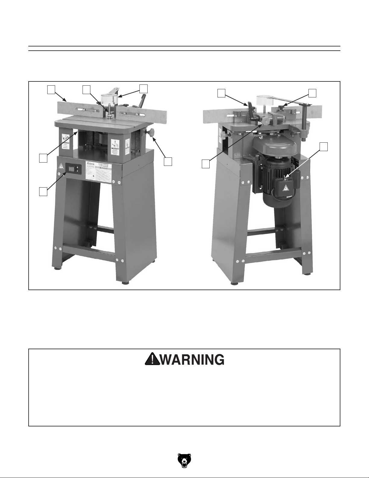
Identification
Become familiar with the names and locations of the controls and features shown below to better understand
the instructions in this manual.
C
B
A
D
E
F
G
H
I
J
A. ON/OFF Switch
B. Spindle Elevation Lever
C. Fence
D. Spindle
E. Cutterhead Guard
F. Spindle Elevation Lock Knob
G. Fence Offset Knob
H. Fence Offset Lock Lever
I. Fence Lock Knob (1 of 2)
J. FOR/REV Switch
For Your Own Safety Read Instruction Manual Before Operating Shaper
a) Wear eye protection.
b) Always keep cutterhead guard in place and in proper operating condition.
c) Be sure keyed washer is directly under spindle nut and spindle nut is tight
d) Feed workpiece AGAINST rotation of cutter.
e) Keep fingers away from revolving cutter–use fixtures when necessary.
f) Do not use awkward hand positions.
Model G0510Z (Mfd. Since 10/16)
-3-
Page 6

Controls &
To reduce your risk of
serious injury, read this
entire manual BEFORE
Components
Fence Offset
Lock Lever
Fence Offset
Knob
Fence
Pivot Knob
(1 of 2)
using machine.
Refer to the following figures and descriptions to
become familiar with the basic controls and components of this machine. Understanding these
items and how they work will help you understand
the rest of the manual and minimize your risk of
injury when operating this machine.
Work Area Controls
Fence
Spindle Elevation Lever
Figure 1. Work area components (front).
Cutterhead
Guard
FOR/REV
Switch
Figure 2. Work area components (rear).
Forward/Reverse (FOR/REV) Switch: Changes
spindle direction for specific work applications.
Switch is located on motor junction box.
Fence Offset Knob: Adjusts fence alignment.
Fence Offset Lock Lever: Locks fence align-
ment setting.
Fence Pivot Knobs: Tighten to lock fence position on table. Loosen to allow entire fence assembly to pivot around cutterhead opening.
Starting Pin
Location
(1 of 2)
Fence: Each fence is independently adjustable
side-to-side, front to back, removable for freehand
shaping, and made of wood for tighter tolerances
with cutterhead.
Cutterhead Guard: Adjusts to protect user from
chips thrown by cutterhead and allows for a clear
view of the workpiece cutting area.
Spindle Elevation Lever: Raises and lowers cutter to desired height.
-4-
ON/OFF
Buttons
Spindle
Elevation
Lock
Figure 3. Work area components (lower).
Starting Pin (see Page 27): Supports workpiece
during beginning of freehand cuts until workpiece
contacts rub collar.
Spindle Elevation Lock: Locks spindle and bit
height adjustments.
ON/OFF Buttons: Turn machine ON and OFF.
Model G0510Z (Mfd. Since 10/16)
Page 7

MACHINE DATA
SHEET
Customer Service #: (570) 546-9663 · To Order Call: (800) 523-4777 · Fax #: (800) 438-5901
MODEL G0510Z 1 HP SHAPER
Product Dimensions:
Weight.............................................................................................................................................................. 167 lbs.
Width (side-to-side) x Depth (front-to-back) x Height..................................................................... 27 x 23 x 40-1/4 in.
Footprint (Length x Width)............................................................................................................... 16-5/8 x 18-7/8 in.
Shipping Dimensions:
Type..................................................................................................................................................... Cardboard Box
Content........................................................................................................................................................... Machine
Weight.............................................................................................................................................................. 172 lbs.
Length x Width x Height....................................................................................................................... 26 x 20 x 23 in.
Must Ship Upright................................................................................................................................................... Yes
Electrical:
Power Requirement........................................................................................................... 120V, Single-Phase, 60 Hz
Full-Load Current Rating........................................................................................................................................ 13A
Minimum Circuit Size.............................................................................................................................................. 15A
Connection Type....................................................................................................................................... Cord & Plug
Power Cord Included.............................................................................................................................................. Yes
Power Cord Length................................................................................................................................................. 6 ft.
Power Cord Gauge......................................................................................................................................... 14 AWG
Plug Included.......................................................................................................................................................... Yes
Included Plug Type................................................................................................................................................ 5-15
Switch Type.................................................................................................................... Push Button ON/OFF Switch
Motors:
Main
Horsepower................................................................................................................................................ 1 HP
Phase............................................................................................................................................ Single-Phase
Amps............................................................................................................................................................ 13A
Speed................................................................................................................................................ 3450 RPM
Type................................................................................................................. TEFC Capacitor-Start Induction
Power Transfer .................................................................................................................................. Belt Drive
Bearings........................................................................................................ Sealed & Permanently Lubricated
Main Specifications:
Operation Info
Max. Cutter Height................................................................................................................................. 2-5/8 in.
Max. Cutter Diameter............................................................................................................................ 2-7/8 in.
Spindle Sizes............................................................................................................................................ 1/2 in.
Spindle Lengths........................................................................................................................................... 3 in.
Exposed Spindle Length........................................................................................................................ 2-7/8 in.
Spindle Cap. Under the Nut................................................................................................................... 2-3/8 in.
Spindle Speeds.............................................................................................................................. 13,200 RPM
Spindle Travel........................................................................................................................................... 7/8 in.
Spindle Openings.................................................................................................................... 1-3/8, 1-3/4, 3 in.
Model G0510Z (Mfd. Since 10/16)
-5-
Page 8

Table Info
Number of Table Inserts................................................................................................................................... 1
Table Insert Sizes I.D.................................................................................................................. 1-3/8, 1-3/4 in.
Table Insert Sizes O.D................................................................................................................................. 3 in.
Table Counterbore Diameter....................................................................................................................... 3 in.
Table Counterbore Depth......................................................................................................................... 3/8 in.
Table Size Length................................................................................................................................ 17-3/4 in.
Table Size Width................................................................................................................................. 15-5/8 in.
Table Size Thickness............................................................................................................................ 1-1/8 in.
Floor to Table Height........................................................................................................................... 34-1/4 in.
Table Fence Length................................................................................................................................... 26 in.
Table Fence Width.................................................................................................................................... 1/2 in.
Table Fence Height............................................................................................................................... 2-3/4 in.
Miter Gauge Info
Miter Angle................................................................................................................................. 0 – 60 deg. L/R
Miter Gauge Slot Type.................................................................................................................... Straight Slot
Miter Gauge Slot Width............................................................................................................................. 3/4 in.
Miter Gauge Slot Height......................................................................................................................... 7/16 in.
Construction
Table....................................................................................................................... Precision-Ground Cast Iron
Base....................................................................................................................................... Pre-Formed Steel
Body Assembly.................................................................................................................................... Cast Iron
Fence................................................................................................................................ Cast Iron with Wood
Miter Gauge............................................................................................................................................. Plastic
Guard....................................................................................................................................................... Plastic
Spindle Bearings........................................................................................ Shielded & Permanently Lubricated
Paint Type/Finish....................................................................................................................... Powder Coated
Other
Mobile Base........................................................................................................................................... D2260A
Other Specifications:
Country of Origin ................................................................................................................................................ China
Warranty ........................................................................................................................................................... 1 Year
Approximate Assembly & Setup Time ...................................................................................................... 1-1/2 Hours
Serial Number Location .................................................................................................................. ID Label on Stand
ISO 9001 Factory .................................................................................................................................................... No
Certified by a Nationally Recognized Testing Laboratory (NRTL) ......................................................................... Yes
Features:
Includes Miter Gauge and Starting Pins
Precision-Ground Cast-Iron Table
Green Powder-Coat Paint
Split Cast-Iron Fence Assembly, Independently Adjustable, with Wood Faces for Offset Profile Shaping
Shielded and Permanently Lubricated Spindle Bearings
Includes 1/4" and 1/2" Router Bit Adapter
Push Button On/Off Switch
Reversing Switch
Cast-Iron Body Construction
Preformed Steel Stand
-6-
Model G0510Z (Mfd. Since 10/16)
Page 9
SECTION 1: SAFETY
For Your Own Safety, Read Instruction
Manual Before Operating This Machine
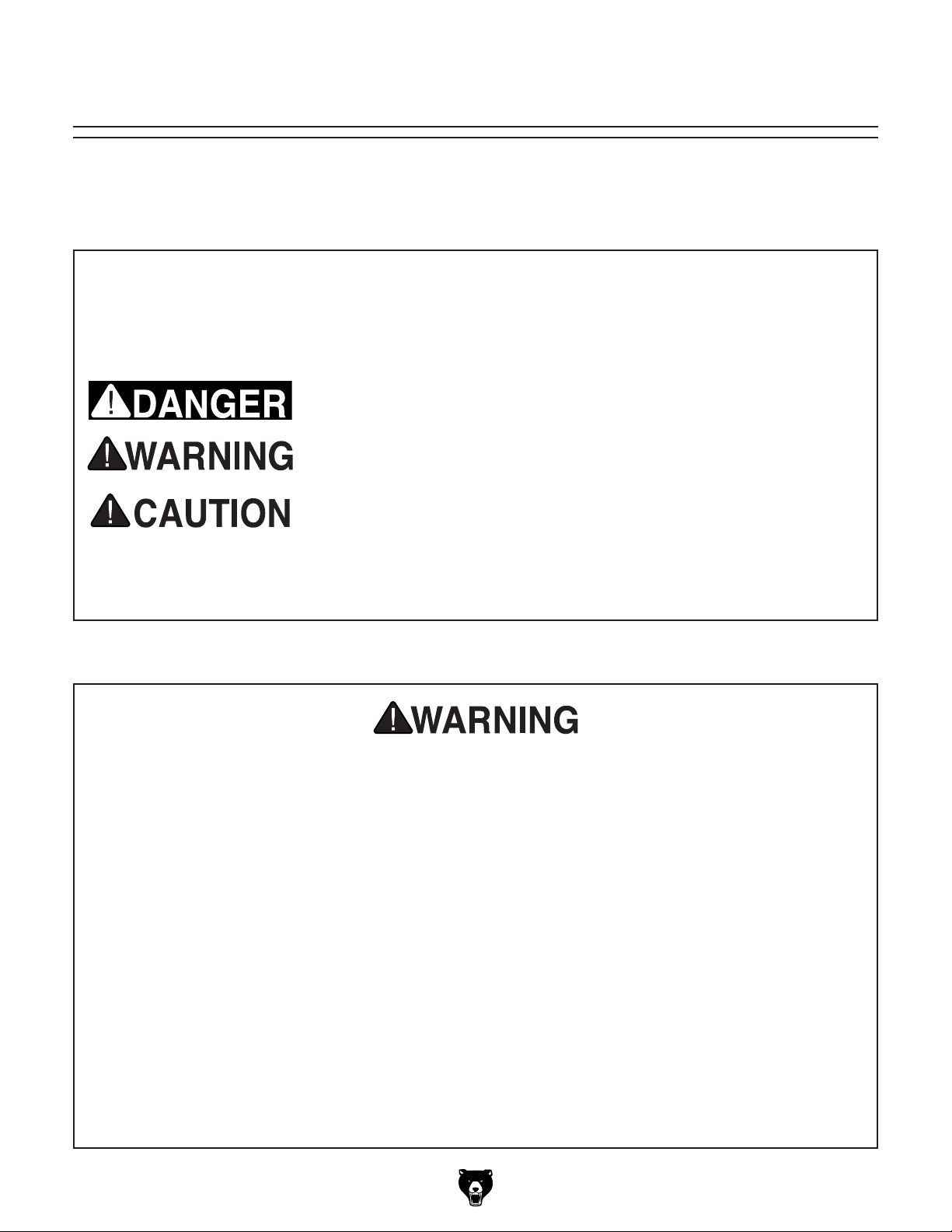
The purpose of safety symbols is to attract your attention to possible hazardous conditions.
This manual uses a series of symbols and signal words intended to convey the level of importance of the safety messages. The progression of symbols is described below. Remember that
safety messages by themselves do not eliminate danger and are not a substitute for proper
accident prevention measures. Always use common sense and good judgment.
Indicates an imminently hazardous situation which, if not avoided,
WILL result in death or serious injury.
Indicates a potentially hazardous situation which, if not avoided,
COULD result in death or serious injury.
Indicates a potentially hazardous situation which, if not avoided,
MAY result in minor or moderate injury. It may also be used to alert
against unsafe practices.
This symbol is used to alert the user to useful information about
NOTICE
proper operation of the machine.
Safety Instructions for Machinery
OWNER’S MANUAL. Read and understand this
owner’s manual BEFORE using machine.
TRAINED OPERATORS ONLY. Untrained operators have a higher risk of being hurt or killed.
Only allow trained/supervised people to use this
machine. When machine is not being used, disconnect power, remove switch keys, or lock-out
machine to prevent unauthorized use—especially
around children. Make workshop kid proof!
DANGEROUS ENVIRONMENTS. Do not use
machinery in areas that are wet, cluttered, or have
poor lighting. Operating machinery in these areas
greatly increases the risk of accidents and injury.
MENTAL ALERTNESS REQUIRED. Full mental
alertness is required for safe operation of machinery. Never operate under the influence of drugs or
alcohol, when tired, or when distracted.
ELECTRICAL EQUIPMENT INJURY RISKS. You
can be shocked, burned, or killed by touching live
electrical components or improperly grounded
machinery. To reduce this risk, only allow qualified
service personnel to do electrical installation or
repair work, and always disconnect power before
accessing or exposing electrical equipment.
DISCONNECT POWER FIRST.
nect machine from power supply BEFORE making
adjustments, changing tooling, or servicing machine.
This prevents an injury risk from unintended startup
or contact with live electrical components.
EYE PROTECTION. Always wear ANSI-approved
safety glasses or a face shield when operating or
observing machinery to reduce the risk of eye
injury or blindness from flying particles. Everyday
eyeglasses are NOT approved safety glasses.
Always discon-
Model G0510Z (Mfd. Since 10/16)
-7-
Page 10

WEARING PROPER APPAREL. Do not wear
clothing, apparel or jewelry that can become
entangled in moving parts. Always tie back or
cover long hair. Wear non-slip footwear to reduce
risk of slipping and losing control or accidentally
contacting cutting tool or moving parts.
HAZARDOUS DUST. Dust created by machinery
operations may cause cancer, birth defects, or
long-term respiratory damage. Be aware of dust
hazards associated with each workpiece material. Always wear a NIOSH-approved respirator to
reduce your risk.
HEARING PROTECTION. Always wear hearing protection when operating or observing loud
machinery. Extended exposure to this noise
without hearing protection can cause permanent
hearing loss.
REMOVE ADJUSTING TOOLS. Tools left on
machinery can become dangerous projectiles
upon startup. Never leave chuck keys, wrenches,
or any other tools on machine. Always verify
removal before starting!
USE CORRECT TOOL FOR THE JOB. Only use
this tool for its intended purpose—do not force
it or an attachment to do a job for which it was
not designed. Never make unapproved modifications—modifying tool or using it differently than
intended may result in malfunction or mechanical
failure that can lead to personal injury or death!
AWKWARD POSITIONS. Keep proper footing
and balance at all times when operating machine.
Do not overreach! Avoid awkward hand positions
that make workpiece control difficult or increase
the risk of accidental injury.
CHILDREN & BYSTANDERS. Keep children and
bystanders at a safe distance from the work area.
Stop using machine if they become a distraction.
GUARDS & COVERS. Guards and covers reduce
accidental contact with moving parts or flying
debris. Make sure they are properly installed,
undamaged, and working correctly BEFORE
operating machine.
FORCING MACHINERY. Do not force machine.
It will do the job safer and better at the rate for
which it was designed.
NEVER STAND ON MACHINE. Serious injury
may occur if machine is tipped or if the cutting
tool is unintentionally contacted.
STABLE MACHINE. Unexpected movement during operation greatly increases risk of injury or
loss of control. Before starting, verify machine is
stable and mobile base (if used) is locked.
USE RECOMMENDED ACCESSORIES. Consult
this owner’s manual or the manufacturer for recommended accessories. Using improper accessories will increase the risk of serious injury.
UNATTENDED OPERATION. To reduce the
risk of accidental injury, turn machine OFF and
ensure all moving parts completely stop before
walking away. Never leave machine running
while unattended.
MAINTAIN WITH CARE. Follow all maintenance
instructions and lubrication schedules to keep
machine in good working condition. A machine
that is improperly maintained could malfunction,
leading to serious personal injury or death.
DAMAGED PARTS. Regularly inspect machine
for damaged, loose, or mis-adjusted parts—or
any condition that could affect safe operation.
Immediately repair/replace BEFORE operating
machine. For your own safety, DO NOT operate
machine with damaged parts!
MAINTAIN POWER CORDS. When disconnecting cord-connected machines from power, grab
and pull the plug—NOT the cord. Pulling the cord
may damage the wires inside. Do not handle
cord/plug with wet hands. Avoid cord damage by
keeping it away from heated surfaces, high traffic
areas, harsh chemicals, and wet/damp locations.
EXPERIENCING DIFFICULTIES. If at any time
you experience difficulties performing the intended operation, stop using the machine! Contact our
Technical Support at (570) 546-9663.
-8-
Model G0510Z (Mfd. Since 10/16)
Page 11

Additional Safety for Shapers
Serious cuts, amputation, entanglement, or death can occur from contact with rotating cutter.
Cutters or other parts improperly secured to spindle can fly off and strike nearby operators with
great force. Flying debris can cause eye injuries or blindness. To minimize risk of getting hurt
or killed, anyone operating shaper MUST completely heed hazards and warnings below.
AVOIDING CUTTER CONTACT: Keep unused
portion of cutter below table. Use smallest table
insert possible. Adjust fences and guards as close
as practical to cutter, or use a zero-clearance
fence or box guard. Always keep some type of
guard or other protective device between your
hands and cutter at all times!
PROTECT HANDS/FINGERS: While feeding
workpiece, avoid awkward hand positions. Never
pass hands directly over, or in front of, cutter. As
one hand approaches a 6-inch radius point from
cutter, move it in an arc motion away from cutter,
and reposition it on the outfeed side.
FEEDING WORKPIECE: To reduce risk of accidental cutterhead contact, always use push blocks
or some type of fixture, jig, or hold-down device
to safely feed workpiece while cutting. Use an
outfeed support table if shaping long workpieces
to ensure proper support throughout entire cutting
procedure. ALWAYS feed workpiece AGAINST
rotation of cutter. NEVER start shaper with workpiece contacting cutter!
CUTTING DEPTH: Never attempt to remove too
much material in one pass. Doing this increases
risk of workpiece kickback. Instead, make several light passes—this is a safer way to cut and it
leaves a cleaner finish.
SMALL WORKPIECES: There is a high risk of
accidental cutter contact with small workpieces,
because they are closer to cutter and more difficult to control. To reduce your risk, only feed small
workpieces using jigs or holding fixtures that allow
your hands to stay safely away from cutter. When
possible, shape longer stock and cut to size.
SAFE CUTTER CLEARANCES: Operator or
bystanders may be hit by flying debris if cutter contacts fence, guard, or table insert upon
startup. Always ensure any new cutter setup has
proper cutter rotational clearance before startup.
SAFE CUTTER INSTALLATION: Improperly
secured knives/inserts, cutters, or rub collars may
become dangerous projectiles if they come loose.
Always ensure keyed washer is directly under
spindle nut and spindle nut is tight. If spindle does
not use a keyed washer, always use two spindle
nuts together, and ensure BOTH are tight. Never
use cutters/bits rated for an RPM lower than
spindle speed.
AVOIDING CLIMB CUTS: Feeding workpiece in
same direction of cutter rotation is a “climb cut.”
Climb cutting can aggressively pull workpiece—
and hands—into cutter. Always first verify direction of cutter rotation before starting, and always
feed workpiece AGAINST cutter rotation.
WORKPIECE CONDITION: Shaping a workpiece
with knots, holes, or foreign objects increases
risk of kickback and cutter damage/breakage.
Thoroughly inspect and prepare workpiece before
shaping. Always “square up” a workpiece before
shaping or flatten workpiece edges with a jointer
or planer. Rough, warped, or wet workpieces
increase risk of kickback.
CUTTER POSITIONING: Whenever possible,
make shaping cuts with cutter on underside of
workpiece to reduce operator exposure to cutter.
Model G0510Z (Mfd. Since 10/16)
SAFETY GUARDS. To reduce risk of unintentional contact with cutter, always ensure included cutter guard, or a properly dimensioned box guard, or
some other type of guard is installed and correctly
positioned before operation.
CONTOUR SHAPING: To reduce risk of unintentional cutter contact while freehand shaping
or using a rub collar as a guide, always use an
overhead or “ring” type guard. To reduce kickback
risk, always use starting pin or pivot board when
starting the cut. NEVER start shaping at a corner!
-9-
Page 12

SECTION 2: POWER SUPPLY
Before installing the machine, consider the availability and proximity of the required power supply
circuit. If an existing circuit does not meet the
requirements for this machine, a new circuit must
be installed. To minimize the risk of electrocution,
fire, or equipment damage, installation work and
electrical wiring must be done by an electrician or
qualified service personnel in accordance with all
applicable codes and standards.
or equipment damage
may occur if machine is
not properly grounded
and connected to power
The full-load current rating is the amperage a
machine draws at 100% of the rated output power.
On machines with multiple motors, this is the
amperage drawn by the largest motor or sum of all
motors and electrical devices that might operate
at one time during normal operations.
The full-load current is not the maximum amount
of amps that the machine will draw. If the machine
is overloaded, it will draw additional amps beyond
the full-load rating.
If the machine is overloaded for a sufficient length
of time, damage, overheating, or fire may result—
especially if connected to an undersized circuit.
To reduce the risk of these hazards, avoid overloading the machine during operation and make
sure it is connected to a power supply circuit that
meets the specified circuit requirements.
For your own safety and protection of
Note: Circuit requirements in this manual apply to
a dedicated circuit—where only one machine will
be running on the circuit at a time. If machine will
be connected to a shared circuit where multiple
machines may be running at the same time, consult an electrician or qualified service personnel to
ensure circuit is properly sized for safe operation.
A power supply circuit includes all electrical
equipment between the breaker box or fuse panel
in the building and the machine. The power supply circuit used for this machine must be sized to
safely handle the full-load current drawn from the
machine for an extended period of time. (If this
machine is connected to a circuit protected by
fuses, use a time delay fuse marked D.)
This machine is prewired to operate on a power
supply circuit that has a verified ground and meets
the following requirements:
process. DO NOT connect to power until
Availability
Electrocution, fire, shock,
Serious injury could occur if you connect
machine to power before completing setup
instructed later in this manual.
110V Circuit Requirements
Nominal Voltage .................... 110V, 115V, 120V
Cycle .......................................................... 60 Hz
Phase ........................................... Single-Phase
Power Supply Circuit ......................... 15 Amps
supply.
Full-Load Current Rating
Full-Load Current Rating at 110V ...... 13 Amps
-10 -
property, consult an electrician if you are
unsure about wiring practices or electrical
codes in your area.
Model G0510Z (Mfd. Since 10/16)
Page 13

Improper connection of the equipment-grounding
wire can result in a risk of electric shock. The
wire with green insulation (with or without yellow
stripes) is the equipment-grounding wire. If repair
or replacement of the power cord or plug is necessary, do not connect the equipment-grounding
wire to a live (current carrying) terminal.
Check with a qualified electrician or service personnel if you do not understand these grounding
requirements, or if you are in doubt about whether
the tool is properly grounded. If you ever notice
that a cord or plug is damaged or worn, disconnect it from power, and immediately replace it with
a new one.
We do not recommend using an extension cord
with this machine.
cord, only use it if absolutely necessary and only
on a temporary basis.
Extension cords cause voltage drop, which can
damage electrical components and shorten motor
life. Voltage drop increases as the extension cord
size gets longer and the gauge size gets smaller
(higher gauge numbers indicate smaller sizes).
Any extension cord used with this machine must
be in good condition and contain a ground wire
and matching plug/receptacle. Additionally, it must
meet the following size requirements:
Grounding & Plug Requirements
it will not fit the outlet, have a qualified
electrician install the proper outlet with a
This machine MUST be grounded. In the event
of certain malfunctions or breakdowns, grounding
reduces the risk of electric shock by providing a
path of least resistance for electric current.
This machine is equipped with a power cord that
has an equipment-grounding wire and a grounding
plug. Only insert plug into a matching receptacle
(outlet) that is properly installed and grounded in
accordance with all local codes and ordinances.
DO NOT modify the provided plug!
GROUNDED
5-15 RECEPTACLE
Grounding Prong
5-15 PLUG
Extension Cords
If you must use an extension
Neutral Hot
Figure 4. Typical 5-15 plug and receptacle.
SHOCK HAZARD!
Two-prong outlets do not meet the grounding
requirements for this machine. Do not modify
or use an adapter on the plug provided—if
verified ground.
Model G0510Z (Mfd. Since 10/16)
Minimum Gauge Size ...........................12 AWG
Maximum Length (Shorter is Better).......50 ft.
-11-
Page 14

SECTION 3: SETUP
This machine was carefully packaged for safe
transport. When unpacking, separate all enclosed
items from packaging materials and inspect them
for shipping damage.
,
please
IMPORTANT:
you are completely satisfied with the machine and
have resolved any issues between Grizzly or the
shipping agent. You MUST have the original pack-
aging to file a freight claim. It is also extremely
helpful if you need to return your machine later.
Keep children and pets away
from plastic bags or packing
materials shipped with this
get help from other people
The following items are needed, but not included,
for the setup/assembly of this machine.
Needed for Setup
This machine presents
serious injury hazards
to untrained users. Read
through this entire manual to become familiar with
the controls and operations before starting the
machine!
Wear safety glasses during
the entire setup process!
Description Qty
• Precision Level ........................................... 1
• Safety Glasses (for each person) ............... 1
• Solvent/Cleaner .......................................... 1
• Shop Rags .................................................. 1
• Brass Hammer ........................................... 1
• Lifting Straps (Rated for at least 750 lbs.) . . 2
• Lifting Equipment
(Rated for at least 750 lbs.) ........................ 1
• Another Person .......................................... 1
HEAVY LIF T!
Straining or crushing injury
may occur from improperly
lifting machine or some of
its parts. To reduce this risk,
and use a forklift (or other
lifting equipment) rated for
weight of this machine.
Unpacking
If items are damaged
call us immediately at (570) 546-9663.
Save all packaging materials until
SUFFOCATION HAZARD!
machine. Discard immediately.
-12-
Model G0510Z (Mfd. Since 10/16)
Page 15

Inventory
The following is a list of items shipped with your
machine. Before beginning setup, lay these items
out and inventory them.
If any non-proprietary parts are missing (e.g. a
nut or a washer), we will gladly replace them; or
for the sake of expediency, replacements can be
obtained at your local hardware store.
Inventory (Figures 5–6): Qty
A. Shaper Assembly ....................................... 1
B. Stand Sides w/Feet .................................... 2
C. Safety Guard Mounting Post ...................... 1
D. Fence Assembly ......................................... 1
E. Fence Faces ............................................... 2
F. Miter Bar w/Handle ..................................... 1
G. Stand Cross Braces ................................... 2
H. Miter Gauge ................................................ 1
I. Router Bit Collet
J. Router Bit Collet
K. Safety Guard .............................................. 1
L. Flat Wrench 27mm ..................................... 1
M. Safety Guard Attachment Bar .................... 1
N. Table Insert 1
O. Stand Hardware Bag
—Carriage Bolts
—Flat Washers
—Hex Nuts
P. Fence/Guard Hardware Bag
—Star Knobs M8-1.25 ................................ 2
—Fender Washers 8mm ............................ 2
—Hex Bolts M8-1.25 x 12........................... 2
—Phillips Head Screws M8-1.25 x 20 ........ 4
—Flat Washers 8mm ................................. 6
—Phillips Head Screws M4-.7 x 10 ............ 2
—Hex Nuts M4-.7 ....................................... 2
Q. Router Table Spacer Kit
—Spacers
—Hex Bolts M12-1.75 x 40 ......................... 5
—Hex Bolts M12-1.75 x 30 ......................... 2
—Lock Washers 12mm .............................. 7
R. Combo Wrench 8/10mm (not shown) ......... 1
S. Combo Wrench 12/14mm (not shown) ....... 1
T. Combo Wrench 27/30mm (not shown) ....... 1
1
⁄2 " ................................... 1
1
⁄4" .................................... 1
3
⁄4" ......................................... 1
5
⁄16"-18 x 1⁄2 " ................... 16
3
⁄8" ................................... 16
5
⁄16"-18 ................................... 16
1
⁄2 " ............................................. 7
A
Figure 5. Shaper assembly.
B
C
D
I
J
K
L
M
E
G
F
N
O
P
Q
H
Figure 6. Shaper inventory components.
NOTICE
If you cannot find an item on this list, carefully check around/inside the machine and
packaging materials. Often, these items get
lost in packaging materials while unpacking or they are pre-installed at the factory.
Model G0510Z (Mfd. Since 10/16)
-13-
Page 16

Hardware Recognition Chart
USE THIS CHART TO MATCH UP
HARDWARE DURING THE INVENTORY
AND ASSEMBLY PROCESS.
Flat
Head
Cap
Screw
-14-
5mm
5mm
Model G0510Z (Mfd. Since 10/16)
Page 17

The unpainted surfaces of your machine are
coated with a heavy-duty rust preventative that
prevents corrosion during shipment and storage.
This rust preventative works extremely well, but it
will take a little time to clean.
Be patient and do a thorough job cleaning your
machine. The time you spend doing this now will
give you a better appreciation for the proper care
of your machine's unpainted surfaces.
There are many ways to remove this rust preventative, but the following steps work well in a wide
variety of situations. Always follow the manufacturer’s instructions with any cleaning product you
use and make sure you work in a well-ventilated
area to minimize exposure to toxic fumes.
Before cleaning, gather the following:
• Disposable rags
• Cleaner/degreaser (WD•40 works well)
• Safety glasses & disposable gloves
• Plastic paint scraper (optional)
Basic steps for removing rust preventative:
1.
2.
3.
4.
Many cleaning solvents
work in a well-ventilated
Avoid chlorine-based solvents, such as
Cleanup
Gasoline and petroleum
products have low flash
points and can explode
or cause fire if used to
clean machinery. Avo id
using these products
to clean machinery.
Put on safety glasses.
Coat the rust preventative with a liberal
amount of cleaner/degreaser, then let it soak
for 5–10 minutes.
Wipe off the surfaces. If your cleaner/degreas-
er is effective, the rust preventative will wipe
off easily. If you have a plastic paint scraper,
scrape off as much as you can first, then wipe
off the rest with the rag.
Repeat Steps 2–3 as necessary until clean,
then coat all unpainted surfaces with a quality
metal protectant to prevent rust.
are toxic if inhaled. Only
area.
NOTICE
acetone or brake parts cleaner, that may
damage painted surfaces.
T23692—Orange Power Degreaser
A great product for removing the waxy shipping grease from the non-painted parts of the
machine during clean up.
Figure 7. T23692 Orange Power Degreaser.
Model G0510Z (Mfd. Since 10/16)
-15-
Page 18

Site Considerations
Weight Load
Refer to the
of your machine. Make sure that the surface upon
which the machine is placed will bear the weight
of the machine, additional equipment that may be
installed on the machine, and the heaviest workpiece that will be used. Additionally, consider the
weight of the operator and any dynamic loading
that may occur when operating the machine.
Space Allocation
Consider the largest size of workpiece that will
be processed through this machine and provide
enough space around the machine for adequate
operator material handling or the installation of
auxiliary equipment. With permanent installations,
leave enough space around the machine to open
or remove doors/covers as required by the maintenance and service described in this manual.
See below for required space allocation.
Physical Environment
Extreme conditions for this type of machinery are
Place this machine near an existing power source.
other hazards. Make sure to leave enough space
Shadows, glare, or strobe effects that may distract
or impede the operator must be eliminated.
Machine Data Sheet for the weight
Children or untrained people
may be seriously injured by
this machine. Only install in an
access restricted location.
The physical environment where the machine is
operated is important for safe operation and longevity of machine components. For best results,
operate this machine in a dry environment that is
free from excessive moisture, hazardous chemicals, airborne abrasives, or extreme conditions.
generally those where the ambient temperature
range exceeds 41°–104°F; the relative humidity
range exceeds 20%–95% (non-condensing); or
the environment is subject to vibration, shocks,
or bumps.
Electrical Installation
Make sure all power cords are protected from
traffic, material handling, moisture, chemicals, or
around machine to disconnect power supply or
apply a lockout/tagout device, if required.
Lighting
Lighting around the machine must be adequate
enough that operations can be performed safely.
= Electrical Connection
Figure 8. Minimum working clearances.
-16 -
23"
27"
Model G0510Z (Mfd. Since 10/16)
Page 19

Assembly
The machine must be fully assembled before it
can be operated. Before beginning the assembly
process, refer to
all
goes smoothly, first clean any
ered or coated in heavy-duty rust preventative (if
applicable).
Needed for Setup and gather
listed items. To ensure the assembly process
parts that are cov-
Note: Sheet steel will often “spring” after it has
been fabricated at the factory, occasionally making it difficult to line up precisely with other parts.
Do not be surprised if the stand requires a bit of
“persuasion” to fit together. On the other hand, if
the parts just do not seem to work together, try
switching parts around (such as cross braces).
To assemble the shaper:
1. Lay one stand side on the ground and attach
the two cross braces with four of the carriage
bolts, washers, and hex nuts as shown in
Figure 9. DO NOT fully tighten the nuts and
bolts at this time.
Figure 10. Stand fully assembled.
3. Place the shaper table upside down on the
two 4x4 blocks, as shown in Figure 11.
Make sure the spindle DOES NOT touch the
ground or the weight of the shaper may damage the spindle.
4. Place the stand assembly on the shaper and
attach it with the remaining eight carriage
bolts, washers and hex nuts, as shown in
Figure 11.
Figure 9. Attaching cross braces to stand side.
2. Attach the remaining stand side to the other
end of the cross braces in the same manner
as step 1. The stand assembly should now
look like Figure 10.
Model G0510Z (Mfd. Since 10/16)
Figure 11. Attaching stand to shaper unit.
5. Have an assistant help you turn the shaper
unit rightside-up.
6. Level the shaper, then tighten all of the
assembly bolts on the stand.
-17-
Page 20

7. Place the fence assembly over the studs that
are already mounted to the shaper table.
8. Use the large diameter flat washers and star
knobs to tighten the fence assembly to the
table.
9. Mount the fence faces to the fence assembly
with the Phillips head screws and flat washers, as shown in Figure 12.
Note: Make sure that the Phillips head
screws are beyond the outer surface of the
fence faces.
12. Insert the mounting post into the bracket that
is bolted to the back of the shaper table, and
tighten the star knob to lock the mounting
post in place.
13. Secure the attachment bar to the mounting
post with the hex bolts.
14. Attach the safety guard with the Phillips head
screws and hex nuts. The completed assembly of the safety guard should now look like
Figure 13.
Figure 12. Mounting fence faces to fence
assembly.
10. Place the straightedge against the fence
faces and align them as close as possible.
11. Inspect the entire length of both fences for
gaps that indicate the fences are not in a
straight line with each other.
—If the fences are straight, then no further
adjustments are necessary.
—If the fences are not straight, then they
should be resurfaced on a jointer as one
unit. Refer to Truing the Fence on Page
36 for instructions on how to do this.
Figure 13. Safety guard components correctly
assembled on shaper.
The guard protects the operator from inadvertent contact with the cutter which could
cause serious personal injury. DO NOT
operate the shaper with the guard removed.
Always replace the guard before operation if
it has been removed for machine service or
maintenance.
-18-
Model G0510Z (Mfd. Since 10/16)
Page 21

Preparing Spindle
DO NOT start machine until all preceding
setup instructions have been performed.
Operating an improperly set up machine
ed results that can lead to serious injury,
for Test Run
To ensure your safety during the test run, make
sure the spindle nut and rub collars are tight, or
just completely remove the spindle nut and rub
collars. If these items are loose during the Te st
Run, they could fly off and strike operator or
bystanders with great force.
To prepare the spindle for the test run:
1. Place a wrench on the spindle flats at the top
of the spindle.
2. Place a wrench on the drawbar nut located
underneath the table (Figure 14) and make
sure the spindle is tight.
Test Run
Once assembly is complete, and your assembled
shaper looks like Figure 15, you are ready to test
run the machine.
Spindle
Flats
Spindle
Nut
Rub
Collars
Drawbar
Nut
Figure 14. Checking spindle to make sure it is
tight (pulley guard removed for clarity).
3. Remove the spindle nut and all the installed
rub collars.
may result in malfunction or unexpect-
death, or machine/property damage.
Figure 15. Model G0510Z assembled and ready
for a test run.
To test run machine:
1. Clear all setup tools away from machine.
2. Connect machine to power supply.
3. Turn FOR/REV direction switch located on
motor to FOR setting. Turn machine ON.
Verify motor operation, and then turn machine
OFF.
4. Switch motor direction to REV, and turn
machine ON.
Motor should run smoothly and without vibra-
tion or unusual problems or noises in both
directions.
Correct any strange or unusual nois-
es before operating machine further (see
Troubleshooting on Page 32). Always disconnect machine from power when investigating or correcting problems. If problems
persist, call Tech Support for help.
Model G0510Z (Mfd. Since 10/16)
Congratulations! The Test Run is now complete.
Continue to Operations section.
-19 -
Page 22

SECTION 4: OPERATIONS
The purpose of this overview is to provide the novice machine operator with a basic understanding
of how the machine is used during operation, so
the
discussed later
in this manual
Due to the generic nature of this overview, it is
not
more about specific operations,
manual and
rienced
research outside of this manual by reading "howto" books, trade magazines, or websites.
To reduce your risk of
serious injury, read this
entire manual BEFORE
To reduce risk of eye injury from flying
Operation Overview
To complete a typical shaping operation, the
operator does the following:
1. Examines workpiece to make sure it is suit-
able for shaping.
machine controls/components
are easier to understand.
intended to be an instructional guide. To learn
read this entire
seek additional training from expe-
machine operators, and do additional
using machine.
chips or lung damage from breathing dust,
always wear safety glasses and a respirator
when operating this machine.
2. Chooses, installs, and adjusts shaper cutter
or router bit to desired height.
3. Adjusts fence to desired position then locks it
in place.
4. Checks outfeed side of machine for proper
fence support and to make sure workpiece
can safely pass through cutter/bit without
interference.
5. Removes any clothing, apparel, or jewelry
that may become entangled in shaper.
6. Puts on safety glasses, respirator, and hearing protection.
7. Turns machine ON.
8. Verifies cutter rotation and feed direction.
9. Feeds workpiece through the cut while main-
taining firm pressure on workpiece against
both table and fence, while always keeping
hands and fingers out of the cutting path.
If you are not experienced with this type
of machine, WE STRONGLY RECOMMEND
that you seek additional training outside of
this manual. Read books/magazines or get
formal training before beginning any projects. Regardless of the content in this section, Grizzly Industrial will not be held liable
for accidents caused by lack of training.
-20-
10. Turns machine OFF.
Model G0510Z (Mfd. Since 10/16)
Page 23

Shaper Cutters or
Router Bits
Installing Cutters
Shaper Cutters
Pros—Shaper cutters are larger, more durable
and generally last longer than router bits. If you
plan on cutting many linear feet of a certain profile, then shaper cutters are the best choice.
Cons—Shaper cutters are more expensive than
router bits and are generally larger, which makes
them less compatible for small projects.
The Model G0510Z is ready to use shaper cutters
when shipped. If you plan on using shaper cutters
with your shaper, read Installing Cutters on this
page.
Router Bits
Pros—Router bits are much cheaper than shaper
cutters and come in a wider range of profiles and
sizes. If you plan on making smaller projects that
do not require many linear feet of cutting, then
router bits are the best choice.
Cons—Router bits are not as durable as shaper
cutters, and because of their small size, they lend
themselves better to the faster speeds of a router.
If you plan to use router bits in your shaper, you
must first convert the shaper to a router table.
Refer to the Router Table Conversion instructions on Page 34 to learn how to do this.
The G0510Z operates at 13,200 RPM, and
the provided spindle is designed for
cutters. Always check the rated speed for any
cutter before installing it. If the shaper is faster
than the rated speed of the cutter, then the cutter may fly apart during operation and cause
injury. Do not use cutters rated for speeds
lower than the spindle!
Tools Needed: Qty
Open-End Wrench 23mm.................................. 1
Open-End Wrench 8mm.................................... 1
To install shaper cutter:
1. DISCONNECT MACHINE FROM POWER!
2. Place a spacer or collar (if needed) at base of
spindle to support cut at desired height.
3. Place cutter on spindle and make sure cutter
rotation direction is correct.
4. Place an appropriate spacer or collar (if
needed) above cutter (refer to Page 26 for
more information).
5. Place spindle washer on top of spacers/cutter, and thread on spindle nut (see Page 19).
6. Tighten spindle nut while holding spindle stationary with an 8mm wrench on spindle flats
for leverage, as shown in Figure 16.
1
⁄2" bore
Model G0510Z (Mfd. Since 10/16)
Figure 16. Tightening spindle lock nut.
-21-
Page 24

Installing Router Bits
Changing Rotation
In order to use router bits, you must first convert
the shaper to a router table. Refer to the Router
Table Conversion instructions on Page 36 to
learn how to do this. The Model G0510Z comes
1
⁄2 " and 1⁄4" router bit collets for use with router
with
bit shanks of the same size.
Always check the rated speed for any router bit
before installing it. If the shaper is faster than
the rated speed of the cutter, then the cutter
may fly apart during operation and cause injury.
Do not use router bits rated for speeds
lower than the spindle!
Tools Needed: Qty
Spindle Wrench 26mm ...................................... 1
Open-End Wrench 30mm ................................. 1
To install router bit:
Always check the direction of the cutter rotation before any shaping operation.
The G0510Z is equipped with a FOR/REV (forward and reverse) switch, as shown in Figure 18.
In most cases, the shaper should be run in the
FOR direction. If you are using router bits, always
run the shaper in the FOR direction. Router bits
are not designed to run backwards.
In some instances, it will be necessary to flip the
cutter over and reverse the cutter rotation.
Whenever possible, mount the cutter so the stock
is milled on the bottom side (the side away from
the operator). This does a better job and it is safer
for the operator. Refer to Rub Collars, Page 26.
1. DISCONNECT MACHINE FROM POWER!
2. Loosen collet nut and insert router bit all the
way (see Figure 17).
3. Use spindle elevation lever (see Figure 17)
to raise spindle and gain access to spindle
flats beneath table.
4. Hold spindle flats with spindle wrench, and
tighten collet nut, as shown in Figure 17.
Hold 26mm
Spindle
Flats w/Flat
Wrench Here
Tighten
Collet Nut
Figure 18. FOR/REV switch.
-22-
Figure 17. Tightening collet nut.
Model G0510Z (Mfd. Since 10/16)
Page 25

Adjusting Spindle
Height
The spindle height is adjustable to allow for precision positioning of cutter/bit exposure from the
table surface.
After making adjustments, it is extremely important to always lock the spindle in place before
operating the shaper. Otherwise, the spindle position can easily shift, causing inconsistent cutting
results from workpiece to workpiece.
Fence Adjustments
Each side of the fence is independently adjustable
to compensate for different cutting thicknesses
and special shaping applications. One turn of the
adjustment knob (see Figure 21) moves the split
fence approximately
material from the whole face of your workpiece,
the outfeed fence should be adjusted to the proper offset to provide support for the workpiece as it
passes over the cutter.
To adjust the fence for straight shaping:
3
/64" (.040"). When removing
To adjust cutter height:
1. Loosen spindle elevation lock shown in
Figure 19.
Spindle
Elevation
Lock
Figure 19. Spindle elevation lock knob.
2. Move spindle up or down with elevation
adjustment lever, shown in Figure 20, until
desired spindle height is obtained.
1. Loosen the lock handle (see Figure 21).
Fence Offset
Knob
Fence Offset
Lock Lever
Figure 21. Controls for fence adjustments.
2. Adjust the infeed fence so the cutter will
remove the desired amount of stock.
3. A test piece can help determine the best
setting. Select the wood for the test piece
that most closely resembles your actual
workpiece.
Spindle Elevation Lever
Figure 20. Spindle elevation lever.
3. Lock spindle into position with lock knob.
Model G0510Z (Mfd. Since 10/16)
Note: To help determine the best setting,
select wood for a test piece that most closely
resembles your actual workpiece.
4. Lock the infeed fence in position with the
locking handle to prepare to make a test cut.
-23-
Page 26

The fence may not always be perfectly parallel to miter slot; therefore, using miter gauge
can cause binding and possible kickback of
workpiece towards operator. DO NOT use
miter gauge to feed material along fence
face when straight shaping. Use a push
stick and hold-downs to keep workpiece in
position.
Straight Shaping
Attempting to operate the shaper without
proper knowledge of the machine could
cause serious injury or death! Read through
the entire manual carefully before attempting
to make any cuts with your shaper.
5. Turn the shaper ON and advance a 36" or
longer test sample of the desired cut about
8'', then stop. Swing the test piece away from
the cutter and turn the machine OFF.
6. When the cutter comes to a complete stop,
adjust the outfeed fence to support the new
profiled edge. Lock the outfeed fence into
position and retest. See Figures 22–23
for improper and proper outfeed fence
positioning.
Figure 22. Improper outfeed fence adjustment.
When shaping straight stock, use the fence
assembly. Refer to Fence Board Alignment
on Page 36 for information on aligning fences.
Grizzly offers hold-down accessories, or shopmade hold-downs can also be used to help guide
workpiece.
To shape straight stock:
1. Install an appropriate cutter onto spindle.
2. Check the cutter rotation.
3. Adjust the spindle height for the desired cut.
4. Lock spindle height into position with the
spindle elevation lock.
5. Position the fences for your desired depth-ofcut.
6. Position the hold-down or other safety device
(see Figures 24–25), and put on safety
glasses and dust mask/respirator.
Figure 23. Proper outfeed fence adjustment.
-24-
Figure 24. Safety boards and push stick in use.
Model G0510Z (Mfd. Since 10/16)
Page 27

Always use cutterhead guard, and only
use a miter gauge to shape end of your
workpiece.
Figure 25. Anti-kickback board buddies in use.
(Guard removed for clarity—ALWAYS use the
guard!)
Partial Face Removal
To partially remove stock face:
1. DISCONNECT MACHINE FROM POWER!
2. Adjust the infeed fence to the approximate
desired depth of cut, and lock the infeed
fence in place.
3. Use a straightedge to adjust the outfeed
fence to the same plane as the infeed fence,
and lock the outfeed fence in place.
4. Set the right and left wood faces to barely clear the cutter (see Figure 27). This
allows the maximum support possible for the
workpiece while passing the cutter.
Note: Remember to tighten the wood fence
faces before starting the shaper.
Fence
7. To test your setup, run a scrap piece of stock
through the shaper using your left hand to
support the workpiece against the fence and
your right hand to feed, as shown in Figure
26. Switch hands for clockwise rotation.
Figure 26.
8. Confirm the sample stock has been shaped
properly, make any final adjustments, and
run the workpiece through the shaper.
Feeding a scrap piece into the shaper
to test the setup.
Workpiece
Figure 27. Lateral fence alignment.
5. Run a test piece through the shaper.
c
l
r
o
e
c
t
n
u
o
C
Direction Of Feed
k
w
i
s
e
Model G0510Z (Mfd. Since 10/16)
Figure 28. Partial feed fence adjustment.
-25-
Page 28

Perimeter Cutting
Rub Collars
When a workpiece requires all sides to receive a
shaped profile, it is important to begin with the end
grain sides before cutting the long grain side. As a
cutter approaches the edge of end grain, a small
amount of tear-out will commonly occur. By running end grain edges first, the tear-out is removed
when the long grain cuts are completed.
Completing cuts in multiple passes (when possible) rather than one heavy cut, will often produce
cleaner results and can prolong cutter life.
To cut an edge around the workpiece perimeter:
1. Cut the workpiece sides (1 & 2) with the end
grain first (see Figure 29).
2. Cut the sides (3 & 4) with the grain last to
make parallel with sides in previous step, or
in sequence, as shown in Figure 29.
1
4
3
Rub collars are used when shaping curved or
irregular workpieces, such as arched doors or
round table tops, and to limit the depth of your
cut. When using a solid rub collar, do not use
excessive pressure when running your workpiece
through the shaper. Otherwise, a groove may
burn into your pattern and be transferred to your
workpiece. Instead, take several passes, using
lighter pressure against the rub collar.
There are two types of rub collars—solid and
ball-bearing. While the Model G0510Z comes
with solid rub collars, Grizzly carries an extensive
line of ball bearing rub collars as upgrades. See
Accessories on Page 30.
Use rub collars in any of the following positions:
1. Rub collar below cutter: When the rub col-
lar is placed below the cutter (see Figure
30), cut progress can be observed. However,
any unintentional movement may lift the
workpiece into the cutter, damaging your
work and creating a dangerous situation. We
DO NOT recommend using a rub collar in this
position.
2
Direction of Feed
Figure 29. Starting perimeter cutting with the
end grain cut.
Not
Recommended!
Rub Collar
Rub
Below
Collar
Cutter
Figure 30. Cutting with rub collar below cutter.
-26-
Model G0510Z (Mfd. Since 10/16)
Page 29

2. Rub collar above cutter: The cut cannot be
seen during operation when the rub collar is
above the cutter (see Figure 31). However,
this offers some advantages—the stock is
not affected by slight variations in thickness
and accidental lifting will not damage the
workpiece. Simply correct any change in
height by repeating the operation.
Rub Collar
Above
Above
Cutter
Irregular Shaping
Freehand shaping greatly increases chance
that operator may lose control of workpiece;
therefore, use a starting pin to increase
control while freehand shaping. Loss of
control could result in loss of fingers or
other serious personal injury.
Irregular or freehand shaping takes a high degree
of skill and dexterity. The fence assembly is not
used in irregular shaping, so rub collars must
be used. Refer to Rub Collars on Page 26 for
details.
Figure 31. Cutting with rub collar above cutter.
3. Rub collar between two cutters: Using
a rub collar between two cutters offers the
distinct advantage of performing two cuts at
once or eliminating the need to change cutters for two different operations (see Figure
32). Notice that part of your workpiece edge
remains uncut and rides along the rub collar.
Rub Collar
Rub
Between
Collar
Cutters
Figure 32. Using rub collar between cutters.
When doing freehand work, a starting pin
must be used! The purpose of the starting pin
is to support the workpiece during the beginning
of the cut. Your shaper is supplied with a starting
pin that can be placed in one of the holes located
in the shaper table. The work should be placed
in the starting position, using the starting pin for
support as illustrated in Figure 33.
Figure 33. Always feed against cutter rotation.
Model G0510Z (Mfd. Since 10/16)
-27-
Page 30

Next, carefully swing the workpiece into the cutter
while holding it firmly against the starting pin. After
the cut has been started, the workpiece should be
swung away from the starting pin and supported
just by the rub collar, as shown by the broken line
positions in Figure 33.
Note: Always feed against the rotation of the
cutter.
Tools Needed: Qty
Open-End Wrench 8mm.................................... 1
Using a Starting Pin
1. DISCONNECT MACHINE FROM POWER!
Using a Starting Block
Sometimes the starting pin will not be in the most
advantageous position. To remedy this situation,
firmly clamp a board in the desired position to act
as a starting block (see Figure 34). Some type of
pivot point must be used.
Clamp
Pattern w/
Hand-Holds
2. Remove fence assembly by removing fence
pivot knobs and flat washers and lifting fence
free.
3. Use wrench to remove threaded fence pivot
bolts.
4. Choose an appropriate cutter for your application and lock it in place.
5. Check cutter rotation.
6. Adjust spindle height to align your workpiece
to cutter.
7. Insert a starting pin into table surface, using
pin location that best supports your workpiece.
8. Use some type of hold-down fixture and
guard when doing freehand work.
9. To test your setup, run a scrap piece of wood
stock through shaper using your left hand to
support workpiece against starting pin and
your right hand to feed. Keep firm pressure
on your workpiece so it runs tight to rub collar. Feed against cutter rotation only.
Starting
Block
Figure 34. Starting fixture in place for jig.
The purpose of the starting block is to support the
workpiece during the beginning of the cut. The
workpiece is typically placed in the starting position, using the starting fixture for support, then
swung into the cutter while holding the workpiece
firmly against the starting fixture. After the cut has
been started, the work is swung away from the
starting fixture and is supported only by the rub
collar. Always feed AGAINST the rotation of
the cutter and do not start cuts at corners in
order to avoid kickback or grain tear-out.
When using a solid rub collar, do not use excessive pressure when running your workpiece
through the shaper. Otherwise, a groove may
burn into your pattern and be transferred to your
workpiece. Instead, take several passes, using
lighter pressure against the rub collar. If you find
this to be a consistent problem, you may consider
using ball bearing rub collars instead of solid collars. See Accessories on Page 30.
Incorrectly feeding stock—feeding WITH
rotation of cutter—creates potentially
uncontrollable feed situation that may pull
stock from your hands. Follow instructions
at all times or serious personal injury can
occur.
-28-
Model G0510Z (Mfd. Since 10/16)
Page 31

Pattern Work
Things to consider when making a pattern or
fixture:
When using a pattern, a rub collar or ball bearing
can be positioned either above, below, or between
cutters.
The pattern is usually used when the entire edge
is to be shaped or when many duplicate pieces
are needed. Pattern work is particularly useful
when rough cutting irregular shapes oversize and
then shaping the edge in a simple two-step operation. A pattern, when attached to a workpiece by
adding toggle clamps, hand-holds, or other safety
devices, make a fixture. Figure 35 shows proper
setup of pattern and bearing rub collar.
You have greater flexibility when choosing the correct diameter rub collar for pattern work than for
non-pattern work. If you look at Figure 35, you will
notice that the position of the pattern determines
the depth of cut. In other words, your pattern size
is dependent upon the inter-relationship of the rub
collar cutting diameter, and the desired amount of
material removed. Changing either the cutter or
the rub collar will change the amount of material
removed. Planning ahead, you can best decide
which rub collars are best suited for your application.
Always perform test cuts on scrap stock to ensure
pattern works as required.
• Use a material that will smoothly follow rub
collar, ball bearing or fence.
• Secure workpiece to a pattern (on sides that
will not be cut) with toggle clamps, or fasten
with wood screws.
• Make your fixture stable! Use proven meth-
ods and materials, and attach hand-holds for
operator comfort and safety.
• Ensure clamps and hidden screws do not
come into contact with cutter.
• Design your fixture so that all cutting occurs
beneath workpiece.
• Always consider rub collar diameter for cor-
rect depth-of-cut when designing your pattern.
• Make sure your workpiece rests flat on work
table, not on work fixture.
• Remember, there are tremendous cutting
forces involved. Fixtures must be solid and
stable, and any workpiece must be firmly
secured.
Rub
Template
Workpiece
Figure 35. The position of the pattern on the
workpiece and bearing size determines the
depth of cut.
Model G0510Z (Mfd. Since 10/16)
Collar
Use care in designing and making fixtures.
Clamps and screws cannot touch the cutter,
and the fixtures must be stable in use, with
the workpiece resting on the shaper table,
not on the fixture. The workpiece must be
fixed securely to the jig.
-29-
Page 32

SECTION 5: ACCESSORIES
Installing unapproved accessories may
order online at www.grizzly.com or call 1-800-523-4777
cause machine to malfunction, resulting in
serious personal injury or machine damage.
To reduce this risk, only install accessories
recommended for this machine by Grizzly.
NOTICE
Refer to our website or latest catalog for
additional recommended accessories.
Basic Eye Protection
T20501—Face Shield Crown Protector 4"
T20502—Face Shield Crown Protector 7"
T20503—Face Shield Window
T20451—“Kirova” Clear Safety Glasses
T20452—“Kirova” Anti-Reflective S. Glasses
H7194—Bifocal Safety Glasses 1.5
H7195—Bifocal Safety Glasses 2.0
H7196—Bifocal Safety Glasses 2.5
T23878—The Missing Shop Manual: Shaper
The tool information you need at your fingertips.
In Missing Shop Manual: Shaper, woodworkers will find out how to best utilize this essential
workshop tool, and how to get the most for their
money by getting the most from their equipment.
From carving decorative contours in wood to cutting perfect joints, woodworkers will discover the
techniques and tips they need to maximize their
shaper's performance. Filled with clear diagrams
and instructions, this concise, pocket-sized portable manual is ideal for quick reference in the
workshop.
T20502
T20452
T20503
H7194
Figure 36. Assortment of basic eye protection.
T20451
Figure 37. T23878 Shaper book.
H5565—Custom Molding Set
Make all the custom moulding you want with this
four piece
mould, C1390 multi form, C1524 crown mould and
C1528 cove mould. Comes complete with wooden
box.
Figure 38. Model H5565 Custom Molding Set.
1
⁄2 " shank set. Contains: C1383 face
-30-
Model G0510Z (Mfd. Since 10/16)
Page 33

SECTION 6: MAINTENANCE
accidental startup, always
disconnect machine from
Cleaning &
To reduce risk of shock or
power before adjustments,
maintenance, or service.
Schedule
For optimum performance from your machine,
follow this maintenance schedule and refer to any
specific instructions given in this section.
Daily Check
• Loose mounting bolts.
• Damaged shaper bits.
• Clean/lubricate table and miter gauge.
• Worn or damaged wires.
• Any other unsafe condition.
Weekly Maintenance
• Check/clean/lubricate offset adjustment on
fence
Monthly Check
• V-belt tension, damage, or wear.
• Clean/vacuum dust buildup from in and
around cabinet and off motor.
• Check/lubricate spindle elevation housing.
Protecting
Cleaning the Model G0510Z is relatively easy.
Vacuum excess wood chips and sawdust, and
wipe off the remaining dust with a dry cloth. Blow
out hard-to-reach areas with compressed air, and
keep the spindle clear of wood dust and chips.
If any resin has built up, use a resin dissolving
cleaner to remove it.
Protect the unpainted cast iron table by wiping
it clean after every use—this ensures moisture
from wood dust does not remain on bare metal
surfaces. Keep the table rust-free with regular
applications of products like G96
SLIPIT
G2871—Boeshield
G2870—Boeshield
Perfect for unpainted cast iron surfaces, this
ozone-friendly protective spray penetrates deep
and really holds up against corrosive environments. Lubricates metals for months and is also
safe for use on most paints, plastics, and vinyls.
Developed by Boeing engineers for aircraft applications—this is the best!
®
, or Boeshield® T-9.
®
T-9 12 oz Spray
®
T-9 4 oz Spray
®
Gun Treatment,
Annually
• Replace V-belt.
Lubrication
The only parts on this machine that require periodic lubrication is where the spindle cartridge
rides on the elevation housing. Use a light grease
or anti-seizing compound on the ways. The frequency of lubrication depends on the amount you
use the shaper. As a habit, inspect this area at
least once a month.
Model G0510Z (Mfd. Since 10/16)
Figure 39. Boeshield® T-9 spray.
-31-
Page 34

Review the troubleshooting and procedures in this section if a problem develops with your machine. If
you need replacement parts or additional help with a procedure, call our Technical Support.
gather the serial number and manufacture date of your machine before calling.
SECTION 7: SERVICE
Troubleshooting
Motor & Electrical
Symptom Possible Cause Possible Solution
Machine does not
start or a breaker
trips.
Machine stalls or is
underpowered.
Machine has
vibration or noisy
operation.
1. Switch disabling lock installed.
2. Power supply switched OFF or at fault.
3. Plug/receptacle at fault/wired wrong.
4. Motor connection wired wrong.
5. Wall circuit breaker tripped.
6. Wiring open/has high resistance.
7. Start capacitor at fault.
8. Spindle switch at fault.
9. Motor at fault.
1. Workpiece material not suitable for
machine.
2. Fence/jig loose or misaligned.
3. Motor wired incorrectly.
4. Plug/receptacle at fault.
5. Pulley slipping on shaft.
6. Motor bearings at fault.
7. Machine undersized for task.
8. Motor overheated.
9. Spindle switch at fault.
10. Motor at fault.
1. Motor or component loose.
2. Cutter at fault.
3. Spindle at fault.
4. Pulley loose.
5. Motor mount loose/broken.
6. Machine incorrectly mounted.
7. Motor fan rubbing on fan cover.
8. Motor bearings at fault.
1. Remove switch disabling lock.
2. Ensure power supply is ON/has correct voltage.
3. Test for good contacts; correct the wiring.
4. Correct motor wiring connections (Page 39).
5. Ensure circuit size is correct/replace weak breaker.
5. Check/fix broken, disconnected, or corroded wires.
7. Test/replace if faulty.
8. Replace switch.
9. Test/repair/replace.
1. Only cut wood/ensure moisture is below 20%.
2. Adjust fence/jig.
3. Wire motor correctly (Page 39).
4. Test for good contacts/correct wiring.
5. Replace loose pulley/shaft.
6. Test/repair/replace.
7. Use correct, sharp cutter; reduce feed rate/depth of
cut.
8. Clean motor, let cool, and reduce workload.
9. Test/replace switch.
10. Test/repair/replace.
1. Inspect/replace damaged bolts/nuts, and re-tighten.
2. Replace damaged cutter.
3. Tighten loose spindle; replace defective spindle or
spindle cartridge.
4. Realign/replace shaft, pulley, set screw, and key.
5. Tighten/replace.
6. Tighten mounting bolts; relocate/shim machine.
7. Fix/replace fan cover; replace loose/damaged fan.
8. Test by rotating shaft; rotational grinding/loose shaft
requires bearing replacement.
Note: Please
-32-
Model G0510Z (Mfd. Since 10/16)
Page 35

Symptom Possible Cause Possible Solution
Workpiece is burned
when cut.
Fuzzy grain. 1. Wood may have high moisture content or
Chipping. 1. Knots or conflicting grain direction in wood.
Divots in the edge of
the cut.
1. Dull cutter.
2. Too slow of a feed rate.
3. Pitch build-up on cutter.
4. Cutter rotating in the wrong direction.
5. Taking too deep of a cut.
surface wetness.
2. Dull cutter.
2. Nicked or chipped cutter.
3. Feeding workpiece too fast.
4. Taking too deep of a cut.
5. Cutting against the grain of the wood.
1. Inconsistent feed speed.
2. Inconsistent pressure against the fence and
rub collar.
3. Fence not adjusted correctly.
1. Replace cutter or have it professionally sharpened.
2. Increase feed speed.
3. Clean cutter with a blade and bit cleaning solution.
4. Reverse the direction of the cutter rotation.
5. Make several passes of light cuts.
1. Check moisture content and allow to dry if moisture
is more than 20%.
2. Replace or have cutter professionally sharpened.
1. Inspect workpiece for knots and grain direction; only
use clean stock.
2. Replace the cutter, or have it professionally
sharpened.
3. Slow down the feed rate.
4. Take a smaller depth of cut. (Always reduce cutting
depth when working with hard woods.)
5. Cut with the grain of the wood.
1. Move smoothly or use a power feeder.
2. Apply constant pressure.
3. Adjust fence.
Model G0510Z (Mfd. Since 10/16)
-33-
Page 36

Router Table
5. Gently tap the bottom of the drawbar to knock
the spindle loose.
Conversion
To use router bits with the shaper, you must convert the shaper to a router table by installing the
provided table spacers and router bit collet. This
process typically takes approximately 20 minutes.
Tools Needed: Qty
Router Bit Adapter ............................................. 1
Spacers
Hex Bolts M12-1.75 x 40 .................................... 5
Hex Bolts M12-1.75 x 30 .................................... 2
Lock Washers 12mm ......................................... 7
Tools Needed: Qty
Flat Wrench 26mm ............................................ 1
Open-End Wrenches 8, 14, 17mm ...........1 Each
To convert shaper for use as a router table:
1. DISCONNECT SHAPER FROM POWER
1
⁄2 " ........................................................ 7
SOURCE!
6. Remove the spindle/drawbar assembly from
the spindle cartridge.
7. Place the desired collet into the collet nut
by pushing it in until it snaps into place (see
Figure 41).
Collet Nut
Collet
Figure 41. Collet snapped into collet nut.
2. Remove the spindle lock nut and any cutters
or rub collars installed on the spindle.
3. Remove table from the shaper by undoing the
seven bolts that secure it in place.
4. Loosen and remove the taper nut (see Figure
40) while holding the top of the spindle with a
wrench.
Taper Nut
8. Insert the collet into the spindle cartridge and
tighten the collet nut until the collet is flush
with the top of the collet nut, as shown in
Figure 42.
Tighten Until
Surfaces Are Flush
Figure 42. Collet flush with top of collet nut.
Figure 40. Removing taper nut from drawbar.
-34-
Model G0510Z (Mfd. Since 10/16)
Page 37

9. Place the table spacers over the table mounting holes on the shaper.
10. Place the table on the spacers and secure
it to the shaper with the hex bolts from the
router table spacer kit (see Figure 43).
7 Spacers
5 Long Bolts
To convert the router table to a shaper:
1. DISCONNECT SHAPER FROM POWER
SOURCE!
2. Remove any router bits that are installed in
the collet.
3. Remove table and table spacers from the
shaper by undoing the seven bolts that
secure the table in place.
4. Replace the table with the original mounting
bolts you removed when you converted the
shaper for use as a router table.
5. Insert the spindle/drawbar assembly into the
spindle cartridge.
6. Thread the drawbar nut onto the bottom of
the drawbar with the taper side up.
2 Short
Bolts
Figure 43.
11. Save the removed table bolts for when you
need to covert the Model G0510Z back to use
as a shaper.
Installing table spacers to convert
shaper to a router table.
Shaper Conversion
Use these procedures to convert the Model
G0510Z from a router table to a shaper.
The Model G0510Z can still use shaper cutters
without removing the table spacers, but you may
not be able to use the full profile of all cutters with
the table in this position.
7. Tighten the taper nut by holding another
wrench on the spindle flats, as shown in
Figure 44.
Spindle Flats
Taper Nut
Figure 44. Tightening taper nut to install shaper
cutter spindle (pulley guard removed for clarity).
Tools Needed: Qty
Flat Wrench 26mm ............................................ 1
Wrench 14mm ................................................... 1
Wrench/Socket 17mm ........................................ 1
Wrench 8mm ..................................................... 1
Wrench 30mm ................................................... 1
Model G0510Z (Mfd. Since 10/16)
-35-
Page 38

Fence Board
Alignment
For safe and accurate shaping, the fence boards
must be parallel with one another so that they
properly support the workpiece through the entire
cutting operation.
Tools Needed Qty
Phillips Screwdriver #2 ...................................... 1
Precision Straightedge 24" ................................ 1
Shims ................................................. As Needed
Truing the Fence
A flat and properly aligned fence creates a safer,
smoother cutting operation. A damaged or worn
fence should be replaced. Be sure to replace
BOTH fences at the same time to ensure each is
properly flattened and align correctly.
To true the fence:
1. Ensure the bolts through the wood fence
facing on each side are tight and adequately
countersunk.
To make the fence boards parallel:
1. DISCONNECT MACHINE FROM POWER!
2. Make sure the fence boards are even with
each other, then place the straightedge
against both fence boards, as shown in
Figure 45.
Straightedge
Figure 45. Example of aligning fence boards.
2. To align the fence faces, rotate the fence
offset knob so they are in alignment. Microadjust and check alignment with a straightedge.
3. If the fences are not coplanar with each other,
remove both fences and resurface as one
unit. You can perform this operation on a
jointer, as shown in Figure 46.
Make sure screws are countersunk deep
enough so workpiece will not come in
contact with heads of screws! Check screw
depth after each pass to ensure that screws
will not contact knives!
— If there is a gap between the straight-
edge and the fence boards, use shims as
needed between the fence boards and
the mounting brackets to make the boards
completely parallel with each other along
their entire length.
-36-
Figure 46. Resurfacing fences on a jointer.
Model G0510Z (Mfd. Since 10/16)
Page 39

Replacing the Spindle
Cartridge Assembly
The spindle cartridge assembly features factorysealed bearings. A sealed bearing requires no
lubrication during its lifetime.
If a bearing fails, your shaper will probably develop a noticeable rumble, which increases when the
machine is put under load. If allowed to worsen,
overheating of the housing containing the bad
bearing could occur, which may cause the bearing
to seize and possibly damage other parts of the
machine.
3. Take off the spindle pulley cover by removing
the two mounting bolts shown in Figure 47.
Rather than disassemble the spindle cartridge
to remove the bad bearings, Grizzly offers
replacement spindle cartridge assemblies (Part#
P0510Z317) as whole units, which makes replacement very simple. The whole procedure can be
accomplished in 15-20 minutes.
Tools Needed: Qty
Flat Wrench 26mm ............................................ 1
Wrench/Socket 19mm ....................................... 1
Wrench 14mm ................................................... 1
Wrench 8mm ..................................................... 1
Replacement Spindle Cartridge Assembly ....... 1
To replace the spindle cartridge assembly:
1. DISCONNECT SHAPER FROM POWER
SOURCE!
2. Remove the spindle and drawbar from the
spindle cartridge assembly. (Remove tapered
drawbar nut and tap the drawbar up to knock
it loose.)
Figure 47. Spindle pulley cover mounting bolts.
4. Loosen the two motor mount bolts, slide the
motor forward, and remove the V-belt.
5. Loosen the spindle lock knob.
6. Remove the cartridge nut on the bottom of
the spindle, as shown in Figure 48, and slide
the pulley off.
Model G0510Z (Mfd. Since 10/16)
Figure 48. Loosening spindle cartridge nut.
7. Hold your hand under the spindle cartridge
and remove the elevation handle by unthreading it counterclockwise. The spindle cartridge
should drop into your hand.
8. Install the new cartridge assembly in the
reverse order of disassembly.
-37-
Page 40

These pages are current at the time of printing. However, in the spirit of improvement, we may make changes to the electrical systems of future machines. Compare the manufacture date of your machine to the one
number and manufacture date of your
machine before calling. This information can be found on the main machine label.
machine
SECTION 8: WIRING
stated in this manual, and study this section carefully.
If there are differences between your machine and what is shown in this section, call Technical Support at
(570) 546-9663 for assistance BEFORE making any changes to the wiring on your machine. An updated
wiring diagram may be available. Note: Please gather the serial
Wiring Safety Instructions
SHOCK HAZARD. Working on wiring that is con-
nected to a power source is extremely dangerous.
Touching electrified parts will result in personal
injury including but not limited to severe burns,
electrocution, or death. Disconnect the power
from the machine before servicing electrical components!
MODIFICATIONS. Modifying the wiring beyond
what is shown in the diagram may lead to unpredictable results, including serious injury or fire.
This includes the installation of unapproved aftermarket parts.
WIRE CONNECTIONS. All connections must
be tight to prevent wires from loosening during
machine operation. Double-check all wires disconnected or connected during any wiring task to
ensure tight connections.
CIRCUIT REQUIREMENTS. You MUST follow
the requirements at the beginning of this manual
when connecting your machine to a power source.
WIRE/COMPONENT DAMAGE. Damaged wires
or components increase the risk of serious personal injury, fire, or machine damage. If you notice
that any wires or components are damaged while
performing a wiring task, replace those wires or
components.
MOTOR WIRING. The motor wiring shown in
these diagrams is current at the time of printing
but may not match your machine. If you find this
to be the case, use the wiring diagram inside the
motor junction box.
CAPACITORS/INVERTERS. Some capacitors
and power inverters store an electrical charge for
up to 10 minutes after being disconnected from
the power source. To reduce the risk of being
shocked, wait at least this long before working on
capacitors.
EXPERIENCING DIFFICULTIES. If you are experiencing difficulties understanding the information
included in this section, contact our Technical
Support at (570) 546-9663.
The photos and diagrams
included in this section are
best viewed in color. You
can view these pages in
color at www.grizzly.com.
-38-
Model G0510Z (Mfd. Since 10/16)
Page 41

The motor wiring shown here is
current at the time of printing, but it
may not match your machine.
Always use the wiring diagram
Electrical Components & Wiring
Figure 49. ON/OFF switch. Figure 50. Forward/Reverse switch.
inside the motor junction box.
FWD/REV SWITCH
Neutral
Wt
Gn
Hot
Bk
Ground
Wt
Gn
Bk
Ground
120 VAC
5-15 Plug
(As Recommended)
Gn
Wt
Bk
ON/OFF SWITCH
(viewed from behind)
1 2 3
Wt
4 5 6
Bk
Bk
2 4
1
Rd
Wt
Wt
Bk
3
MOTOR
Wt
Wt
Rd
Ground
Start
Capacitor
200MFD
125VAC
Model G0510Z (Mfd. Since 10/16)
READ ELECTRICAL SAFETY
ON PAGE 38!
-39-
Page 42

We do our best to stock replacement parts when possible, but we cannot guarantee that all parts shown
are available for purchase. Call (800) 523-4777 or visit www.grizzly.com/parts to check for availability.
272
274
275
254
255
256
277
280
311
281
282
290
281
292
246
211
221
270
278-3
213
221
262
258
250
265
268
269
246
278-1
SECTION 9: PARTS
246
245
244
243
247
213
215
221
213
314
251
266
266
318
319
276
293
291
278-2
315
291
308
317
283
284
320
316
300V2-2
300V2-4
288
263
206
257
298
299
300V2
312
300V2-1
300V2-3
300V2-6
300V2-7
300V2-8
300V2-9
285
286
287
264
267
301
300V2-5
324
242
248
219
249
231
297
221
223
238
221
306
219
304
221
303
241
313
240
289
227
214
216
220
213
294
221
211
316
201
228
230
295V3
204
202
229
219
236-1
239
226
236-4
236-2
219
217
309
224
218
296
210A
211
206
205
232
233
236
236-3
310
208
221
209
307A-2
235
231
225
234
236-6
236-5
279
207
212
307A-1
307A
237
-40-
203
321 323322
Model G0510Z (Mfd. Since 10/16)
Page 43

Parts List
REF PART # DESCRIPTION REF PART # DESCRIPTION
201 P0510Z201 SIDE PANEL 241 P0510Z241 HEX NUT M6-1
202 P0510Z202 TIE BAR 242 P0510Z242 HALF COLLAR
203 P0510Z203 TAPER NUT M8-1.25 243 P0510Z243 PHLP HD SCR M6-1 X 12
204 P0510Z204 RUBBER FOOT 244 P0510Z244 ADJUSTING SCREW STUD
205 P0510Z205 FLAT WASHER 4MM 245 P0510Z245 STAR KNOB 8MM, PINNED
206 P0510Z206 HEX NUT M4-.7 246 P0510Z246 ROLL PIN 3 X 20
207 P0510Z207 EXT TOOTH WASHER 5MM 247 P0510Z247 FENCE BODY LEFT
208 P0510Z208 HEX NUT M5-.8 248 P0510Z248 CLAMP STUD
209 P0510Z209 CARRIAGE BOLT 5/16-18 X 1/2 249 P0510Z249 HEX NUT M12-1.75
210A P0510Z210A SHELF V2.07.07 250 P0510Z250 MOUNTING BRACKET
211 P0510Z211 HEX NUT 5/16-18 251 P0510Z251 HEX BOLT M8-1.25 X 30
212 P0510Z212 PHLP HD SCR M5-.8 X 12 254 P0510Z254 RUB COLLAR 1/2 X 1-3/16 X 3/16
213 P0510Z213 HEX BOLT M8-1.25 X 12 255 P0510Z255 RUB COLLAR 1/2 X 1-3/16 X 1/4
214 P0510Z214 TABLE SUPPORT 256 P0510Z256 RUB COLLAR 1/2 X 1-3/16 X 3/8
215 P0510Z215 SPINDLE PULLEY GUARD 257 P0510Z257 STAR KNOB BOLT M10-1.5 X 28
216 P0510Z216 LOCK WASHER 1/2" 258 P0510Z258 GUARD MOUNTING POST
217 P0510Z217 HEX BOLT M12-1.75 X 20 262 P0510Z262 GUARD ATTACHMENT BAR
218 P0510Z218 TABLE LEG 263 P0510Z263 PHLP HD SCR M4-.7 X 12
219 P0510Z219 FLAT WASHER 1/2" 264 P0510Z264 SAFETY GUARD
220 P0510Z220 HEX BOLT M12-1.75 X 25 265 P0510Z265 HOUSING BRACKET
221 P0510Z221 FLAT WASHER 3/8" 266 P0510Z266 HEX BOLT M12-1.75 X 30
223 P0510Z223 BELT GUARD 267 P0510Z267 CLAMP SLEEVE RIGHT
224 P0510Z224 WORKING TABLE 268 P0510Z268 CLAMP SLEEVE LEFT
225 P0510Z225 TABLE INSERT 1-3/4" 269 P0510Z269 STUFF RING
226 P0510Z226 TAPER PIN 270 P0510Z270 LOCK BAR
227 P0510Z227 CLAMP STUD 272 P0510Z272 STAR KNOB 12MM, PINNED
228 P0510Z228 FLAT WASHER 5/16" 274 P0510Z274 SPINDLE NUT
229 P0510Z229 STAR KNOB (FEMALE) M8-1.25 275 P0510Z275 SAFETY WASHER
230 P0510Z230 FENCE BODY RIGHT 276 P0510Z276 SPINDLE CARTRIDGE
231 P0510Z231 FENCE 1 PC 277 P0510Z277 CUTTER SPINDLE V2.02.08
232 P0510Z232 FLAT WASHER 8MM 278-1 P0510Z278-1 ROUTER BIT COLLET NUT
233 P0510Z233 PHLP HD SCR M8-1.25 X 20 278-2 P0510Z278-2 ROUTER BIT COLLET 1/2"
234 P0510Z234 TABLE INSERT 1-3/8" 278-3 P0510Z278-3 ROUTER BIT COLLET 1/4"
235 P0510Z235 PHLP HD SCR M4-.7 X 25 279 P0510Z279 UNPLUG MACHINE LABEL
236 P0510Z236 COMPLETE MITER GAUGE 280 P0510Z280 INT RETAINING RING 47MM
236-1 P0510Z236-1 MITER BAR 281 P0510Z281 BALL BEARING 6204
236-2 P0510Z236-2 MITER GAUGE BODY 282 P0510Z282 SPINDLE HOUSING
236-3 P0510Z236-3 FLAT WASHER 6MM 283 P0510Z283 BEARING CONE
236-4 P0510Z236-4 STAR KNOB M6-1 X 16 284 P0510Z284 COIL SPRING
236-5 P0510Z236-5 POINTER 285 P0510Z285 SET SCREW M8-1.25 X 8
236-6 P0510Z236-6 PHLP HD SCR M4-.7 X 8 286 P0510Z286 SPRING COLLAR
237 P0510Z237 CARTRIDGE NUT M18-1.5 287 P0510Z287 STUD M12-1.75 X 355
238 P0510Z238 LOCK WASHER 3/8" 288 P0510Z288 DRAWBAR M8-1.25 X 130 V2.02.08
239 P0510Z239 LOCK HANDLE M12-1.75 289 P0510Z289 SLIP-ON HANDLE 12MM
240 P0510Z240 PHLP HD SCR M6-1 X 12 290 P0510Z290 BEARING SLEEVE
Safety labels help reduce the risk of serious injury caused by machine hazards. If any label comes
off or becomes unreadable, the owner of this machine MUST replace it in the original location
before resuming operations. For replacements, contact (800) 523-4777 or www.grizzly.com.
Model G0510Z (Mfd. Since 10/16)
-41-
Page 44

Parts List Cont.
REF PART # DESCRIPTION REF PART # DESCRIPTION
291 P0510Z291 LOCK WASHER 12MM 306 P0510Z306 HEX BOLT M12-1.75 X 35
292 P0510Z292 SPINDLE PULLEY 307A P0510Z307A ON/OFF PADDLE SWITCH
293 P0510Z293 KEY 4 X 4 X 20 307A-1 P0510Z307A-1 SWITCH REAR COVER V2.07.07
294 P0510Z294 READ MANUAL LABEL 307A-2 P0510Z307A-2 SWITCH FRONT COVER V2.07.07
295V3 P0510Z295V3 MACHINE LABEL CSA V3.03.17 308 P0510Z308 FWD/REV SWITCH
296 P0510Z296 SAFETY GLASSES LABEL 309 P0510Z309 MOTOR CORD
297 P0510Z297 V-BELT A29 310 P0510Z310 POWER CORD 14G
298 P0510Z298 MOTOR PULLEY 311 P0510Z311 WAVY WASHER 45MM
299 P0510Z299 SET SCREW M6-1 X 10 312 P0510Z312 KEY 5 X 5 X 22
300V2 P0510Z300V2 MOTOR 1HP 120V 1-PH V2.10.16 313 P0510Z313 STRAIN RELIEF
300V2-1 P0510Z300V2-1 FAN COVER 314 P0510Z314 STRAIN RELIEF
300V2-2 P0510Z300V2-2 FAN 315 P0510Z315 FWD/REV SWITCH
300V2-3 P0510Z300V2-3 CAPACITOR 125V 200M (3" X 1") 316 P0510Z316 ELECTRICITY LABEL
300V2-4 P0510Z300V2-4 CAPACITOR COVER 317 P0510Z317 SPINDLE CARTRIDGE ASSEMBLY
300V2-5 P0510Z300V2-5 WIRING BOX 318 P0510Z318 HEX BOLT M12-1.75 X 40
300V2-6 P0510Z300V2-6 CENTRIFUGAL SWITCH 319 P0510Z319 RUB COLLAR 1/2 X 1-3/16 X 1/2
300V2-7 P0510Z300V2-7 CONTACT PLATE 320 P0510Z320 ROUTER TABLE SPACER KIT
300V2-8 P0510Z300V2-8 BALL BEARING 6204ZZ (FRONT) 321 P0510Z321 COMBO WRENCH 8/10MM
300V2-9 P0510Z300V2-9 BALL BEARING 6204ZZ (REAR) 322 P0510Z322 COMBO WRENCH 12/14MM
301 P0510Z301 HEX BOLT M8-1.25 X 35 323 P0510Z323 COMBO WRENCH 27/30MM
303 P0510Z303 HEX NUT M8-1.25 324 P0510Z324 FLAT WRENCH 27MM
304 P0510Z304 MOTOR MOUNT PLATE
Safety labels help reduce the risk of serious injury caused by machine hazards. If any label comes
off or becomes unreadable, the owner of this machine MUST replace it in the original location
before resuming operations. For replacements, contact (800) 523-4777 or www.grizzly.com.
-42-
Model G0510Z (Mfd. Since 10/16)
Page 45

WARRANTY CARD
Name _____________________________________________________________________________
Street _____________________________________________________________________________
City _______________________ State _________________________ Zip _____________________
Phone # ____________________ Email _________________________________________________
Model # ____________________ Order # _______________________ Serial # __________________
The following information is given on a voluntary basis. It will be used for marketing purposes to help us develop
better products and services. Of course, all information is strictly confidential.
1. How did you learn about us?
____ Advertisement ____ Friend ____ Catalog
____ Card Deck ____ Website ____ Other:
2. Which of the following magazines do you subscribe to?
____ Cabinetmaker & FDM
____ Family Handyman
____ Hand Loader
____ Handy
____ Home Shop Machinist
____ Journal of Light Cont.
____ Live Steam
____ Model Airplane News
____ Old House Journal
____ Popular Mechanics
3. What is your annual household income?
____ $20,000-$29,000 ____ $30,000-$39,000 ____ $40,000-$49,000
____ $50,000-$59,000 ____ $60,000-$69,000 ____ $70,000+
CUT ALONG DOTTED LINE
4. What is your age group?
____ 20-29 ____ 30-39 ____ 40-49
____ 50-59 ____ 60-69 ____ 70+
5. How long have you been a woodworker/metalworker?
____ 0-2 Years ____ 2-8 Years ____ 8-20 Years ____ 20+ Years
6. How many of your machines or tools are Grizzly?
____ 0-2 ____ 3-5 ____ 6-9 ____10+
____ Popular Science
____ Popular Woodworking
____ Precision Shooter
____ Projects in Metal
____ RC Modeler
____ Rie
____ Shop Notes
____ Shotgun News
____ Today’s Homeowner
____ Wood
____ Wooden Boat
____ Woodshop News
____ Woodsmith
____ Woodwork
____ Woodworker West
____ Woodworker’s Journal
____ Other:
7. Do you think your machine represents a good value? _____ Yes _____No
8. Would you recommend Grizzly Industrial to a friend? _____Yes _____No
9. Would you allow us to use your name as a reference for Grizzly customers in your area?
Note: We never use names more than 3 times. _____Yes _____No
10. Comments: _____________________________________________________________________
_________________________________________________________________________________
_________________________________________________________________________________
_________________________________________________________________________________
Page 46

FOLD ALONG DOTTED LINE
FOLD ALONG DOTTED LINE
Place
Stamp
Here
GRIZZLY INDUSTRIAL, INC.
P.O. BOX 2069
BELLINGHAM, WA 98227-2069
Send a Grizzly Catalog to a friend:
Name_______________________________
Street_______________________________
City______________State______Zip______
TAPE ALONG EDGES--PLEASE DO NOT STAPLE
Page 47

WARRANTY & RETURNS
Grizzly Industrial, Inc. warrants every product it sells for a period of 1 year to the original purchaser from
the date of purchase. This warranty does not apply to defects due directly or indirectly to misuse, abuse,
negligence, accidents, repairs or alterations or lack of maintenance. This is Grizzly’s sole written warranty
and any and all warranties that may be implied by law, including any merchantability or fitness, for any particular purpose, are hereby limited to the duration of this written warranty. We do not warrant or represent
that the merchandise complies with the provisions of any law or acts unless the manufacturer so warrants.
In no event shall Grizzly’s liability under this warranty exceed the purchase price paid for the product and
any legal actions brought against Grizzly shall be tried in the State of Washington, County of Whatcom.
We shall in no event be liable for death, injuries to persons or property or for incidental, contingent, special,
or consequential damages arising from the use of our products.
To take advantage of this warranty, contact us by mail or phone and give us all the details. We will then issue
you a “Return Number,’’ which must be clearly posted on the outside as well as the inside of the carton. We
will not accept any item back without this number. Proof of purchase must accompany the merchandise.
The manufacturers reserve the right to change specifications at any time because they constantly strive to
achieve better quality equipment. We make every effort to ensure that our products meet high quality and
durability standards and we hope you never need to use this warranty.
Please feel free to write or call us if you have any questions about the machine or the manual.
Thank you again for your business and continued support. We hope to serve you again soon.
Page 48

 Loading...