

Page 1

121⁄2" LEAN & MEAN
PORTABLE PLANER
MODEL G0505
INSTRUCTION MANUAL
COPYRIGHT © DECEMBER, 2002 BY GRIZZLY INDUSTRIAL, INC.
WARNING: NO PORTION OF THIS MANUAL MAY BE REPRODUCED IN ANY SHAPE
OR FORM WITHOUT THE WRITTEN APPROVAL OF GRIZZLY INDUSTRIAL, INC.
PRINTED IN CHINA
ONLINE MANUAL DISCLAIMER
THE INFORMATION IN THIS MANUAL REPRESENTS THE CONFIGURATION OF THE MACHINE AS IT IS CURRENTLY BEING SHIPPED. THE MACHINE
CONFIGURATION CAN CHANGE AS PRODUCT IMPROVEMENTS ARE INCORPORATED. IF YOU OWN AN EARLIER VERSION OF THE MACHINE, THIS
MANUAL MAY NOT EXACTLY DEPICT YOUR MACHINE . CONTACT CUSTOMER SERVICE IF YOU HAVE ANY QUESTIONS ABOUT DIFFERENCES. PREVI-
OUS VERSIONS ARE NOT AVAILABLE ONLINE.
Page 2

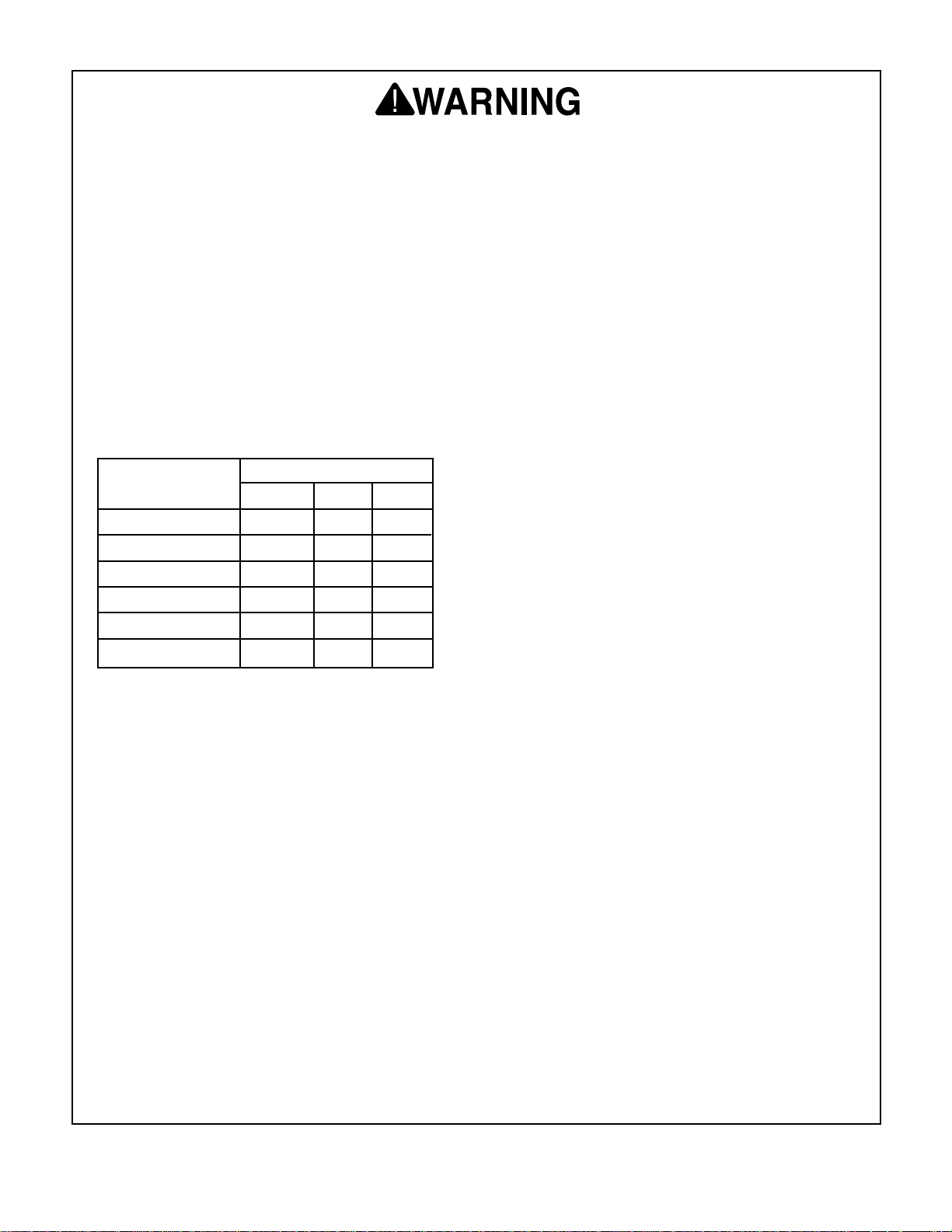
WARNING
Some dust created by power sanding, sawing, grinding, drilling, and other construction activities contains
chemicals known to the State of California to cause
cancer, birth defects or other reproductive harm.
Some examples of these chemicals are:
• Lead from lead-based paints.
• Crystalline silica from bricks, cement, and
other masonry products.
• Arsenic and chromium from chemically treated
lumber.
Your risk from these exposures varies, depending on
how often you do this type of work. To reduce your
exposure to these chemicals: work in a well ventilated
area, and work with approved safety equipment, such
as those dust masks that are specially designed to filter out microscopic particles.
Page 3

Table Of Contents
PAGE
1. SAFETY ....................................................................................................................................2
SAFETY INSTRUCTIONS FOR POWER TOOLS ........................................................2-3
ADDITIONAL SAFETY INSTRUCTIONS FOR THE PORTABLE PLANER......................4
2. INTRODUCTION........................................................................................................................5
3. CIRCUIT REQUIREMENTS ......................................................................................................6
110V OPERATION ............................................................................................................6
GROUNDING ....................................................................................................................6
EXTENSION CORDS ........................................................................................................6
4. IDENTIFICATION ......................................................................................................................7
CONTROLS & FEATURES................................................................................................7
5. SET UP ......................................................................................................................................8
UNPACKING ......................................................................................................................8
PIECE INVENTORY ..........................................................................................................8
HARDWARE RECOGNITION CHART ..............................................................................9
CLEAN UP ......................................................................................................................10
SITE CONSIDERATIONS................................................................................................10
MOUNTING TO BENCH ..................................................................................................11
HANDLE ASSEMBLY ......................................................................................................11
CHIP DEFLECTOR..........................................................................................................12
TEST RUN ......................................................................................................................12
6. OPERATIONS..........................................................................................................................13
ON/OFF SWITCH ............................................................................................................13
RESET BUTTON ............................................................................................................13
DEPTH OF CUT ..............................................................................................................14
PLANING TIPS ................................................................................................................14
WOOD TYPES ................................................................................................................15
WOOD CHARACTERISTICS ....................................................................................15-16
7. MAINTENANCE ......................................................................................................................17
GENERAL ........................................................................................................................17
KNIFE SHARPENING......................................................................................................17
MOTOR ............................................................................................................................18
V-BELT ............................................................................................................................18
FEED ROLLERS..............................................................................................................19
LUBRICATION ................................................................................................................19
8. SERVICE ADJUSTMENTS ......................................................................................................20
EXTENSION WINGS ......................................................................................................20
KNIFE SETTING ........................................................................................................20-21
9. REFERENCE INFO ..................................................................................................................22
MACHINE DATA ..............................................................................................................23
PARTS BREAKDOWN AND PARTS LISTS ..............................................................24-29
WARRANTY AND RETURNS..........................................................................................30
Page 4

-2-
5. KEEP CHILDREN AND VISITORS
AWAY. All children and visitors should be
kept at a safe distance from work area.
6. MAKE WORKSHOP CHILD PROOF with
padlocks, master switches, or by removing
starter keys.
7. NEVER FORCE TOOL. It will do the job
better and safer at the rate for which it was
designed.
8. USE RIGHT TOOL. Do not force tool or
attachment to do a job for which it was not
designed.
1. KEEP GUARDS IN PLACE and in working
order.
2. REMOVE ADJUSTING KEYS AND
WRENCHES. Form habit of checking to
see that keys and adjusting wrenches are
removed from tool before turning on.
3. KEEP WORK AREA CLEAN. Cluttered
areas and benches invite accidents.
4. NEVER USE IN DANGEROUS ENVIRONMENT. Do not use power tools in
damp or wet locations, or where any flammable or noxious fumes may exist. Keep
work area well lighted.
Safety Instructions For Power Tools
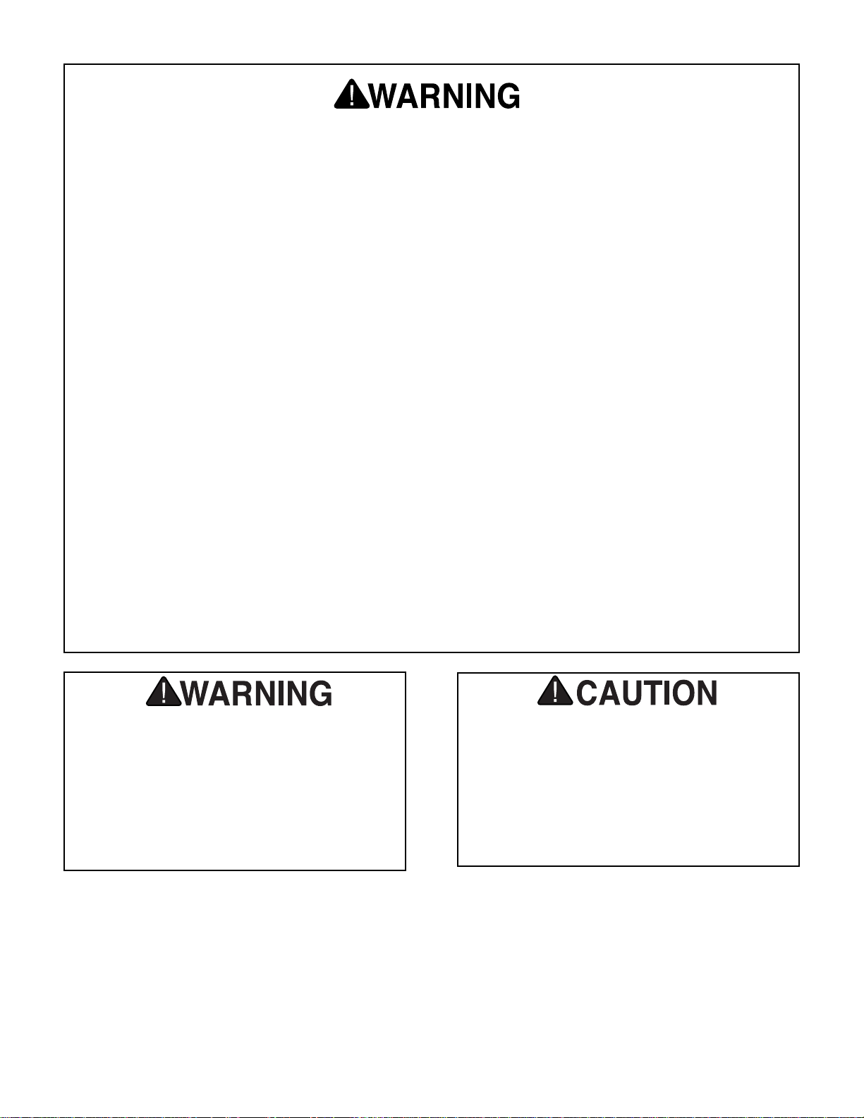
SECTION 1: SAFETY
For Your Own Safety Read Instruction
Manual Before Operating This Equipment
Indicates an imminently hazardous situation which, if not avoided,
WILL result in death or serious injury.
Indicates a potentially hazardous situation which, if not avoided,
COULD
result in death or serious injury.
Indicates a potentially hazardous situation which, if not avoided,
MAY
result in minor or moderate injury. It may also be used to alert
against unsafe practices.
This symbol is used to alert the user to useful information about
proper operation of the equipment.
The purpose of safety symbols is to attract your attention to possible hazardous conditions.
This manual uses a series of symbols and signal words which are intended to convey the level
of importance of the safety messages. The progression of symbols is described below.
Remember that safety messages by themselves do not eliminate danger and are not a substitute for proper accident prevention measures.
NOTICE
G0505 121⁄2" Lean & Mean Portable Planer
Page 5
-3-
9. USE PROPER EXTENSION CORD. Make
sure your extension cord is in good condition. Conductor size should be in accordance with the chart below. The amperage
rating should be listed on the motor or tool
nameplate. An undersized cord will cause
a drop in line voltage resulting in loss of
power and overheating. Your extension
cord must also contain a ground wire and
plug pin. Always repair or replace extension cords if they become damaged.
Minimum Gauge for Extension Cords
10. WEAR PROPER APPAREL. Do not wear
loose clothing, gloves, neckties, rings,
bracelets, or other jewelry which may get
caught in moving parts. Non-slip footwear
is recommended. Wear protective hair covering to contain long hair.
11. ALWAYS USE SAFETY GLASSES. Also
use face or dust mask if cutting operation
is dusty. Everyday eyeglasses only have
impact resistant lenses, they are NOT
safety glasses.
12. SECURE WORK. Use clamps or a vise to
hold work when practical. It’s safer than
using your hand and frees both hands to
operate tool.
13. NEVER OVERREACH. Keep proper foot-
ing and balance at all times.
LENGTH
AMP RATING 25ft 50ft 100ft
0-6 18 16 16
7-10 18 16 14
11-12 16 16 14
13-16 14 12 12
17-20 12 12 10
21-30 10 10 No
Safety Instructions For Power Tools
14. MAINTAIN TOOLS WITH CARE. Keep
tools sharp and clean for best and safest
performance. Follow instructions for lubricating and changing accessories.
15. DISCONNECT TOOLS before servicing
and changing accessories, such as blades,
bits, cutters, and the like.
16. REDUCE THE RISK OF UNINTENTIONAL STARTING. Make sure switch is in off
position before plugging in. Also, the magnetic switch on this machine may start if the
switch gets bumped hard enough.
17. USE RECOMMENDED ACCESSORIES.
Consult the owner’s manual for recommended accessories. The use of improper
accessories may cause risk of injury.
18. CHECK DAMAGED PARTS. Before fur-
ther use of the tool, a guard or other part
that is damaged should be carefully
checked to determine that it will operate
properly and perform its intended function.
Check for alignment of moving parts, binding of moving parts, breakage of parts,
mounting, and any other conditions that
may affect its operation. A guard or other
part that is damaged should be properly
repaired or replaced.
19. NEVER LEAVE TOOL RUNNING UNATTENDED. TURN POWER OFF. Do not
leave tool until it comes to a complete stop.
20. NEVER USE UNDER THE INFLUENCE of
alcohol or drugs, or when tired.
21. NEVER ALLOW UNSUPERVISED OR
UNTRAINED PERSONNEL TO OPERATE THE MACHINE. Make sure any
instructions you give in regards to the operation of the machine are approved, correct,
safe, and clearly understood.
G0505 121⁄2" Lean & Mean Portable Planer
Page 6
-4-
Like all power tools, there is danger associated with the Model G0505 Planer.
Accidents are frequently caused by lack of
familiarity or failure to pay attention. Use
this tool with respect and caution to lessen
the possibility of operator injury. If normal
safety precautions are overlooked or
ignored, serious personal injury may occur.
No list of safety guidelines can be complete.
Every shop environment is different. Always
consider safety first, as it applies to your
individual working conditions. Use this and
other machinery with caution and respect.
Failure to do so could result in serious personal injury, damage to equipment or poor
work results.
Additional Safety Instructions For The
Portable Planer
6. Position yourself so you do not get caught
(pinned) between the lumber and another
obstruction during the planing operation.
Also, ensure that there is sufficient clearance for the material on the outfeed side of
the planer.
7. Keep hands and fingers away from moving
parts and away from the infeed and outfeed
section of the planer. DO NOT reach into
the machine at any time for any reason
without first turning the power switch off,
pulling the electrical plug and after the
machine has come to a full stop.
8. Any glued-up stock must be completely set
up and dry before planing.
9. Never leave the planer running unattended.
10. Habits – good and bad – are hard to break.
Develop good habits in your shop and safety will become second-nature to you.
1. Ensure that the machine is firmly secured
to a bench or table before use.
2. Always be aware of the condition of the
wood you are planing. Pay particular attention to knots, splits, and other potential
areas where the grain may be getting
ready to separate.
3. Perform machine inspection and mainte-
nance services regularly as described in
Section 7: Maintenance.
4. Make sure the planer knives are sharp,
balanced, and set correctly and securely.
Operate planer only with both knives in the
cutterhead.
5. DO NOT plane any man-made composites
such as plywood, hardboard, particle
board, fiber board, flake board, fiberglass
and/or any other material other than solid,
natural wood fiber.
G0505 121⁄2" Lean & Mean Portable Planer
Page 7

-5-
SECTION 2: INTRODUCTION
Grizzly Industrial, Inc. is proud to offer the Model
G0505 12
1
⁄2" Portable Planer. This planer is a part
of Grizzly’s growing family of fine machinery.
When used according to the guidelines described
in this manual, you can expect years of troublefree, enjoyable operation and proof of Grizzly’s
commitment to customer satisfaction.
The Model G0505 is a wood planer designed for
portable or small shop use. This planer features a
2 HP motor, an easy top-mounted depth adjustment, fold-down extension wings, a direct reading
thickness gauge, and convenient carry handles.
We are also pleased to provide this manual with
the Model G0505. It was written to guide you
through assembly, review safety considerations,
and cover general operating procedures. It represents our effort to produce the best documentation possible. If you have any comments regarding this manual, please write to us at the address
below:
Grizzly Industrial, Inc.
C
/O Technical Documentation
P.O. Box 2069
Bellingham, WA 98227-2069
Most important, we stand behind our machines. If
you have any service questions or parts requests,
please call or write us at the location listed below.
Grizzly Industrial, Inc.
1203 Lycoming Mall Circle
Muncy, PA 17756
Phone: (570) 546-9663
Fax: (800) 438-5901
E-Mail: techsupport@grizzly.com
Web Site: http://www.grizzly.com
The specifications, drawings, and photographs
illustrated in this manual represent the Model
G0505 as supplied when the manual was prepared. However, owing to Grizzly’s policy of continuous improvement, changes may be made at
any time with no obligation on the part of Grizzly.
For your convenience, we always keep current
Grizzly manuals available on our website at
www.grizzly.com
. Any updates to your machine
will be reflected in these manuals as soon as they
are complete. Visit our site often to check for the
latest updates to this manual!
Read the manual before
assembly and operation.
Become familiar with
the machine and its
operation before beginning any work. Serious
personal injury may
result if safety or operational information is not
understood or followed.
G0505 121⁄2" Lean & Mean Portable Planer
Page 8

-6-
Grounding
This tool is equipped with an electric cord having
an equipment grounding conductor. Improper
connections of the electrical-grounding conductor
can result in the risk of electric shock. The conductor with green or green and yellow striped
insulation is the electrical grounding conductor. If
repair or replacement of the electric cord or plug
is necessary, do not connect the equipment
grounding conductor to a live terminal.
If you find it necessary to use an extension
cord with this machine:
• Only use a Grade S or heavier-duty cord.
• Only use a cord with a grounding prong.
• Use at least a 18 gauge cord if the cord is 25
feet long or less.
• Use at least a 16 gauge cord if the cord is
between 26-50 feet.
• Use at least a 14 gauge cord if the cord is
between 51-100 feet.
Extension Cords
This machine must have a ground prong in
the plug to help ensure that it is grounded.
DO NOT remove the ground prong from plug
to fit into a two-pronged outlet! If the plug
will not fit the outlet, have the proper outlet
installed by a qualified electrician.
Electrocution or fire may
result if this machine is
not grounded correctly.
Verify that any existing
electrical outlet and circuit
you intend to plug into is
actually grounded. DO
NOT use the machine if it
is not grounded.
SECTION 3: CIRCUIT REQUIREMENTS
110V Operation
The Model G0505 motor is designed to operate at
110V and includes a 110V plug.
Under normal 110V use, the motor draws approximately 10 amps. We recommend that you use a
15 amp circuit breaker or a 15 amp slow-blow
fuse with your machine.
We also recommend that you use a dedicated circuit, (i.e., the Model G0505 should provide the
only draw from that circuit). If frequent circuit failures occur when using the planer, contact our
Service Department or your local electrical contractor.
NOTICE
The Model G0505 cannot be rewired for
220V operation! Attempting to do this will
void the warranty and will ruin the machine.
In the event of a malfunction or breakdown,
grounding provides electric current a path of least
resistance to reduce the risk of electric shock.
G0505 121⁄2" Lean & Mean Portable Planer
Page 9

-7-
SECTION 4: IDENTIFICATION
Controls & Features
To help you understand the set up and operation
instructions, become familiar with the basic features of your new planer.
Please match up the list below with the letters in
Figures 1 and 2 to identify the planer controls
and features.
A. Return Rollers
B. ON/OFF Switch
C. Reset Button
D. Depth Indicator
E. Cutterhead Elevation Handle
F. Chip Deflector
Figure 1. Model G0505 front view controls and
features.
Figure 2. Model G0505 rear view controls and
features.
A
B
C
D
E
F
G0505 121⁄2" Lean & Mean Portable Planer
Page 10
G0505 121⁄2" Lean & Mean Portable Planer
-8-
SECTION 5: SET UP
Unpacking
The Model G0505 is shipped from the manufacturer in a carefully packed carton. If you discover
the machine is damaged after you have signed for
delivery, and the truck and driver are gone, you
will need to file a freight claim with the carrier.
Save the container and all packing materials for
possible inspection by the carrier or its agent.
Without the packing materials, filing a freight
claim can be difficult. If you need assistance
determining whether you need to file a freight
claim, or with the procedure to file one, please
contact our Customer Service.
When you are completely satisfied with the condition of your shipment, you should inventory its
parts.
NOTICE
A full parts list and breakdown can be found
towards the end of this manual. For easier
assembly, or to identify missing parts,
please refer to the detailed illustrations at
the end of the manual.
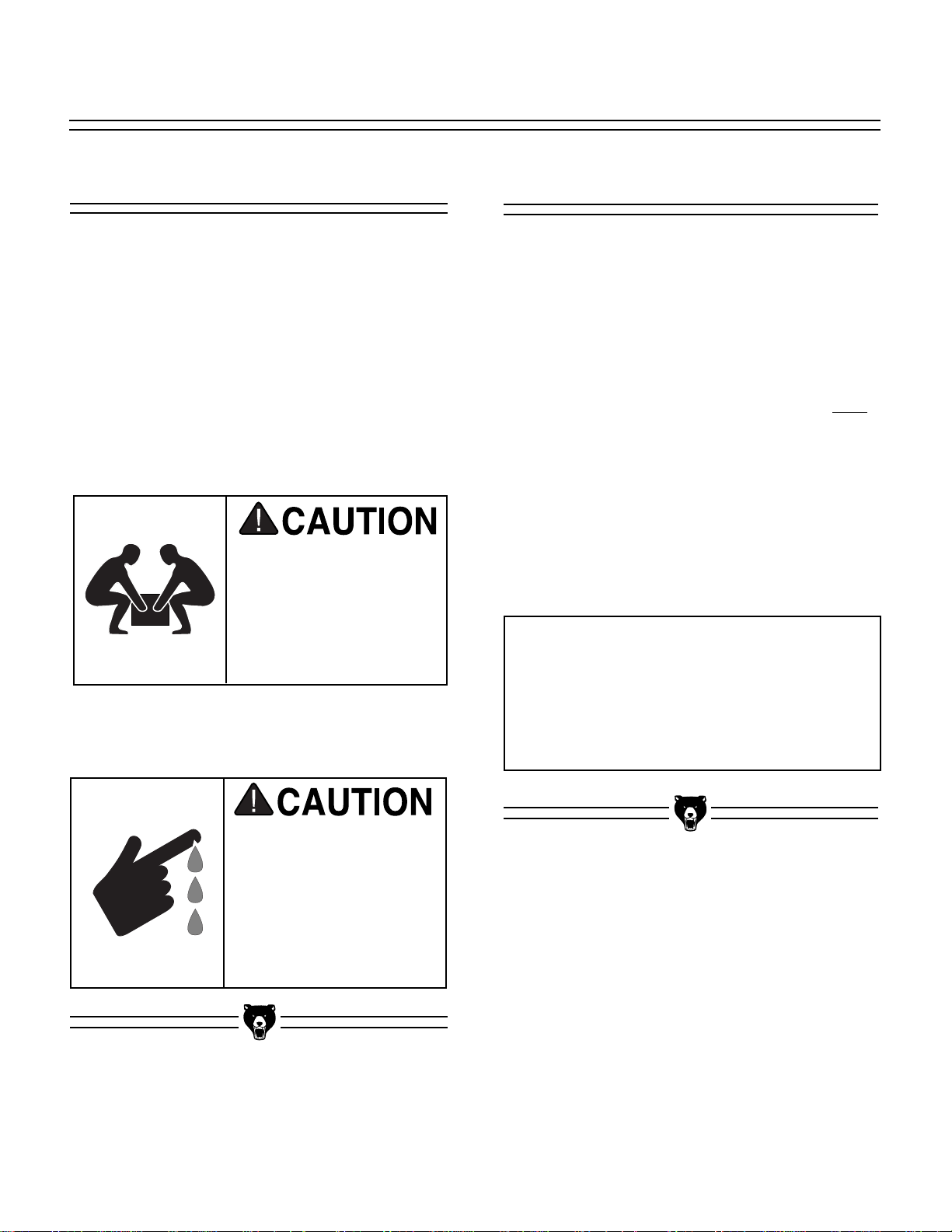
The Model G0505 weighs
approximately 71 lbs. DO
NOT over-exert yourself
while unpacking or moving your machine—get
assistance or use a fork
lift.
Piece Inventory
After all the parts have been removed from the
carton, you should have:
• Planer
• Chip Deflector
• Handle
• 8-10 mm Wrench
• Knife Gauge
• Hardware QTY
—Cap Screw M5-.8 x 20mm ..................(1)
—Wing Nuts M5......................................(2)
—Washers M5 ........................................(2)
In the event that any non-proprietary parts are
missing (e.g. a nut or a washer), we would be glad
to replace them, or for the sake of expediency,
replacements can be obtained at your local hardware store.
Some metal parts may
have sharp edges on
them after they are
formed. Please examine
the edges of all metal
parts before handling
them. Failure to do so
could result in injury.
Page 11
G0505 121⁄2" Lean & Mean Portable Planer
-9-
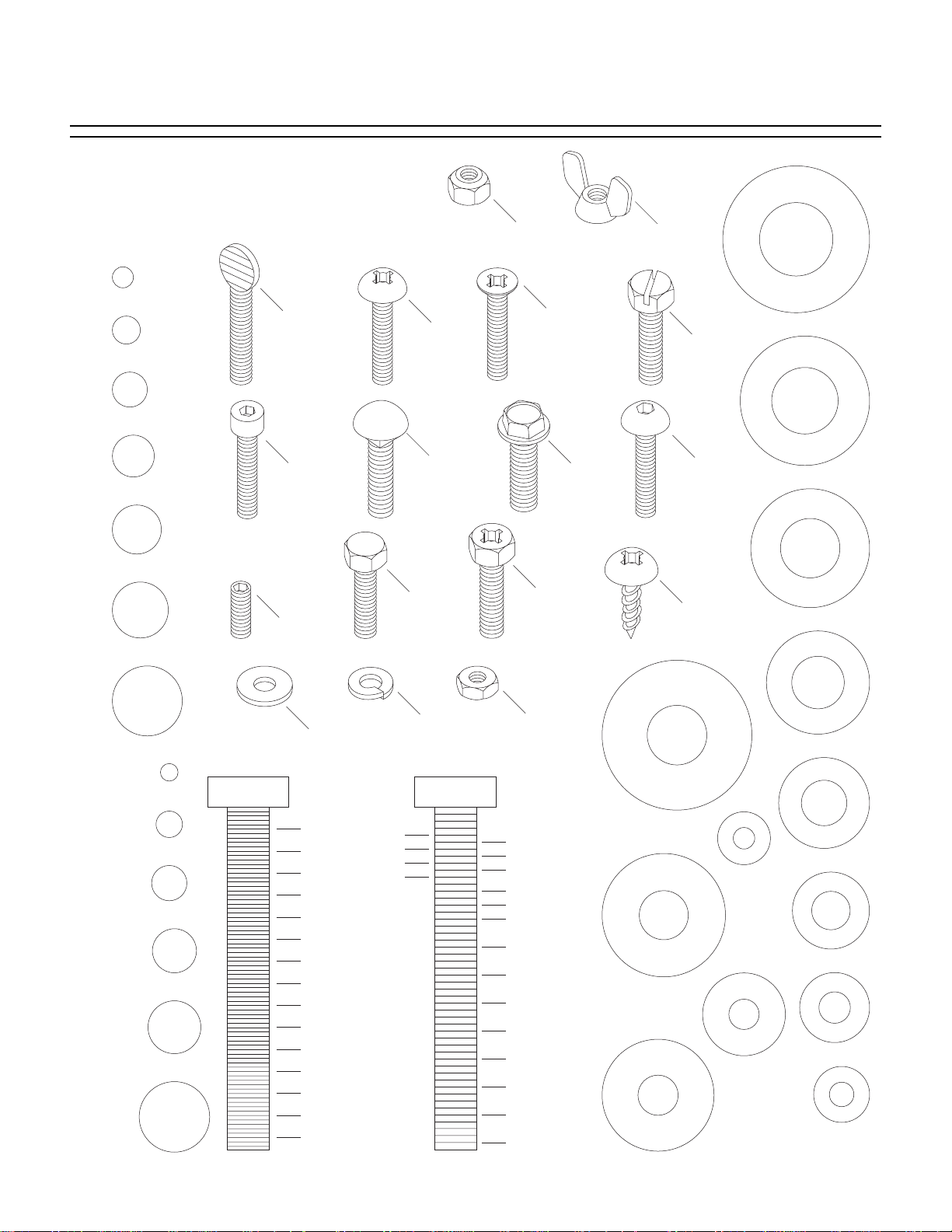
Hardware Recognition Chart
Use this chart to match up hardware
pieces during the assembly process!
Lock
Nut
#
10
1
⁄4''
Thumb
Screw
Phillips
Head
5
⁄16''
3
⁄8''
7
Cap
Screw
⁄16''
Screw
Carriage
Bolt
Hex
1
⁄2''
Setscrew
5
⁄8''
Head
Bolt
Lock
Washer
MEASURE BOLT DIAMETER BY PLACING INSIDE CIRCLE
4mm
6mm
5mm
10mm
8mm
15mm
20mm
Washer
1
⁄4''
3
⁄8''
1
⁄2''
5
⁄8''
25mm
10mm
30mm
35mm
40mm
45mm
12mm
LINES ARE 1MM APART
50mm
55mm
60mm
⁄16'' INCH APART
1
65mm
16mm
70mm
75mm
LINES ARE
Countersunk
Phillips
Head
Screw
Phillips
Head
Hex
Bolt
Hex
Nut
5
⁄16''
7
⁄16''
9
⁄16''
3
⁄4''
7
⁄8''
1''
1
1
⁄4''
1
⁄2''
1
3
⁄4''
1
2
1
⁄4''
2
1
⁄2''
2
3
⁄4''
2
3
D
I
A
R
H
S
W
M
E
T
⁄8''
9
R
D
⁄16''
1
⁄2''
E
R
I
A
M
E
T
E
R
D
I
A
M
E
T
E
R
5
R
E
E
Flange
Bolt
Wing
Nut
Slotted
Screw
Phillips
Button
Head
Screw
S
A
W
E
H
H
S
A
W
A
Head
Sheet
Metal
Screw
D
I
A
R
12mm
D
I
A
D
I
A
M
M
E
T
E
R
D
I
A
R
M
E
H
E
S
T
E
A
R
W
M
4mm
E
T
E
R
D
I
A
R
M
E
E
H
T
S
E
A
R
W
6mm
E
T
E
R
A
S
S
W
H
A
H
E
W
S
A
E
E
H
W
R
10mm
R
8mm
WASHERS ARE MEASURED BY THE INSIDE DIAMETER
D
I
A
R
W
H
S
A
M
E
T
7
⁄16''
E
R
D
I
R
A
M
E
W
H
S
E
3
T
⁄8''
E
R
D
I
A
R
M
E
E
5
T
⁄16''
E
A
R
W
D
I
A
R
M
E
H
E
1
S
⁄4''
T
A
E
R
W
D
I
R
A
E
M
H
E
S
T
A
E
R
W
#
10
E
H
S
A
Page 12

G0505 121⁄2" Lean & Mean Portable Planer
-10-
Clean Up
The unpainted surfaces are coated with a waxy oil
to protect them from corrosion during shipment.
Remove this protective coating with a solvent
cleaner or citrus-based degreaser such as
Grizzly’s G7895 Degreaser. To clean thoroughly,
some parts may need to be removed. For opti-
mum performance from your machine, make
sure you clean all moving parts or sliding contact surfaces that are coated. Avoid chlorine-
based solvents as they may damage painted surfaces should they come in contact. Always follow
the manufacturer’s instructions when using any
type of cleaning product.
Do not use gasoline or
other petroleum-based
solvents to clean with.
They have low flash
points which make them
extremely flammable. A
risk of explosion and
burning exists if these
products are used.
Do not smoke while using
solvents. A risk of explosion or fire exists and may
result in serious personal
injury.
Many of the solvents
commonly used to clean
machinery can be toxic
when inhaled or ingested.
Always work in well-ventilated areas far from
potential ignition sources
when dealing with solvents. Use care when disposing of waste rags and
towels to be sure they do
not create fire or environmental hazards.
Site Considerations
FLOOR LOAD
Your new planer represents a small weight load in
a small sized footprint. Most shop floors will be
adequate for the weight of this machine, the workbench, the operator and the material being
processed; however, some floors may require
additional support. Contact an architect or structural engineer if you have any question about the
ability of your floor to handle the weight.
WORKING CLEARANCES
Working clearances can be thought of as the distances between machines and obstacles that
allow safe operation of every machine without limitation. Consider existing and anticipated machine
needs, size of material to be processed through
each machine, and space for auxiliary stands or
work tables. Also consider the relative position of
each machine for efficient material handling. Be
sure to allow yourself sufficient room to safely run
your machines in any foreseeable operation.
LIGHTING AND OUTLETS
Lighting should be bright enough to eliminate
shadow and prevent eye strain. Electrical circuits
should be dedicated or large enough to handle
combined motor amp loads. Outlets should be
located near each machine so power or extension
cords are not obstructing high-traffic areas. Be
sure to observe local electrical codes for proper
installation of new lighting, outlets or circuits.
Make your shop “child
safe.” Ensure that your
workplace is inaccessible to
children by closing and
locking all entrances when
you are away. DO NOT allow
unsupervised children or
visitors in the shop at any
time.
Page 13

G0505 121⁄2" Lean & Mean Portable Planer
-11-
Mounting to Bench
The planer can be directly mounted to a bench or
table top, or to a Shop Fox
®
Deluxe Tool Table for
increased stability during planing.
To mount the planer:
1. Determine the correct length of hex bolts
needed to mount the planer to your workbench. This will be the height of the planer
mounting holes, plus the thickness of your
workbench, plus an extra
1
⁄2" for washers and
the hex nut.
2. From the hardware store, get (4)
1
⁄8" hex bolts
that meet the length requirements for your
setup. Also get (8)
1
⁄2" flat washers, (4) 1⁄2"
lock washers, and (4)
1
⁄2" hex nuts.
3. Mount the planer to your workbench with
your hardware in the order shown in Figure
3.
Figure 4. Attaching handle.
Figure 3. Mounting planer to bench.
Handle Assembly
To attach the handle assembly:
1. Align the flat portion inside the handle bore
with the flat portion on the shaft.
2. Insert the handle assembly on the shaft that
protrudes out of the top of the planer (see
Figure 4).
3. Thread the M5-.8 x 20mm cap screw through
the handle and into the shaft to secure the
handle in place. DO NOT over-tighten.
Planer Mounting
Hole
Workbench
Page 14

G0505 121⁄2" Lean & Mean Portable Planer
-12-
Chip Deflector
Figure 5. Chip deflector mounting studs.
Mounting Studs
Once assembly is complete, you are ready to test
run the machine.
Test Run
DO NOT attempt to investigate or adjust the
machine while it is running. Wait until the
machine is turned off, unplugged and all
working parts have come to a complete stop
before you do anything!
To test run the planer:
1. Plug the planer into the power source.
2. Move the ON/OFF switch to the ON position.
Make sure that your finger is poised on the
STOP button, just in case there is a problem.
3. Run the Model G0505 for a short time to
ensure that the moving parts are working
properly with no excessive vibration.
The planer should run smoothly, with little or no
vibration or rubbing noises. Strange or unnatural
noises should be investigated and corrected
before operating the machine further.
If any problem develops, correct it before attempting to use the machine.
If you cannot locate the source of unusual noises,
contact our service department for help.
For your safety and for the proper operation of the
machine, ensure that the chip deflector is secured
before operation. The chip deflector directs wood
chips away from the cutterhead during operation,
and it covers the cutterhead and feed rollers for
operator safety.
To secure the chip deflector:
1. Align the chip deflector with the two studs
mounted at the exit side of the planer.
2. Set chip deflector in place and use the two
wing nuts and washers to secure. See Figure
5.
Page 15

G0505 121⁄2" Lean & Mean Portable Planer
-13-
Using this machine produces sawdust that may
cause short and longterm respiratory illness.
Always wear a dust mask
when operating this
planer!
SECTION 6: OPERATIONS
Failure to disconnect
power when working on
machine may cause the
machine to accidentally
start. Disconnect power
before attempting any
adjustments!
!
Loose clothing or long
hair may get caught in
moving parts. Keep
clothing secured and
long hair pulled back.
NOTICE
The following section was designed to give
instructions on the basic operations of this
planer. However, it is in no way comprehensive of every planing application. WE
STRONGLY RECOMMEND that you read
books, trade magazines, or get formal training to maximize the potential of your planer.
ON/OFF Switch
The ON/OFF switch is located on the front of the
planer. See Figure 6. The switch has a key that,
when removed, allows it to be locked in the OFF
position. To access the locking feature, push the
switch to the OFF position and pull the switch key
out. Should the key be removed when the planer
is ON, it can still be turned OFF, but it will not be
able to be restarted until the key is replaced.
Figure 6. Location of switch and reset button.
Reset Button
Reset Button
ON/OFF Switch
Removable
Safety Key
Projectiles thrown from
the machine could cause
serious eye injury. Wear
safety glasses during
operations.
The G0505 Planer comes equipped with a thermal overload protection switch which will trip if the
motor gets too hot. To reset the switch, turn the
switch to the OFF position, wait a few minutes
and then depress the reset button. See Figure 6.
If the reset button does not stay depressed, wait
longer before resetting to allow the machine to
cool down.
Page 16

G0505 121⁄2" Lean & Mean Portable Planer
-14-
Depth Of Cut
The planing depth is controlled by the crank handle on top of the planer. Turning the handle clockwise raises the cutterhead and turning it counter-
clockwise lowers the cutterhead. See Figure 7.
Depth-of-cut is read directly from the inch/millimeter scale located on the top, right-hand side of the
planer. One complete turn of the handle raises or
lowers the cutterhead approximately
5
⁄64'' (2mm).
The range of material thickness that can be
planed is
3
⁄16'' - 6'' (5mm - 152mm).
The maximum depth-of-cut varies according to
the hardness of the wood and how wide of a
board is being passed under the cutterhead.
Generally, we recommend a maximum depth of
no more than
1
⁄32". A series of light cuts will give a
better end result than trying to take off too much
material in a single pass, plus there is less strain
on the motor.
Figure 7. Depth of cut scale and indicator.
Depth Of Cut Indicator
• Inspect your lumber for twisting or cupping,
and surface one face on a jointer if necessary.
• Scrape all glue off when planing glued-up
panels.
• DO NOT plane more than one piece at a
time.
• Remove only
1
⁄32'' (.8mm) of material on each
pass. Remove less material on each pass
when planing wide or dense stock.
• Support the workpiece on both ends. Get
assistance if you are planing long lumber, or
use roller stands to support the workpiece.
• Measure the workpiece thickness with
calipers to get exact results.
• Carefully inspect all stock to make sure it is
free of large knots or foreign objects that may
damage your blades.
• When possible, plane equal amounts on
each side of the board to reduce the chance
of twisting or cupping.
• Use the entire width of the planer to wear
knives evenly.
• Always plane WITH the grain direction of the
wood. Never plain cross-grain or end-grain.
Planing Tips
Page 17

G0505 121⁄2" Lean & Mean Portable Planer
-15-
Figure 8. Common hardwood shear strengths.
The species of wood, as well as its condition, has
a dramatic effect on the depth of cut the planer
can effectively take with each pass. The harder
the wood (as illustrated by its shear strength), the
shallower the depth of cut should be.
Commonly used hardwoods and their associated
shear strengths are illustrated in Figure 8.
Similarly, common softwood shear strengths are
displayed in Figure 9.
Wood Types
Type Shear (PSI)
Black Locust 2,480
Sugar Maple 2,330
Pecan Hickory 2,080
White Oak 2,000
White Ash 1,950
Black Cherry 1,700
American Elm 1,510
Black Walnut 1,370
Red Alder 1,080
Basswood 980
Cottonwood 930
Increasing
Difficulty
Figure 9. Common softwood shear strengths.
Type Shear (PSI)
Western Larch 1,410
Tamarack 1,280
Douglas Fir 1,160
Alaska Cedar 1,130
Sitka Spruce 1,150
Sugar Pine 1,050
Cypress 1,000
Redwood (OG) 940
Red Cedar 860
White Pine 850
Balsam Fir 710
Increasing
Difficulty
Wood Characteristics
Below is a list of wood characteristics you may
encounter when planing. The following descriptions of defects will give you some possible
answers to problems you may encounter while
planing different materials. Possible solutions follow the descriptions.
Chipped Grain
Problem—Usually a result of cutting against the
grain, planing lumber with knots or excessive
amount of cross grain, or using dull knives.
Solution—Decrease depth of cuts. Inspect your
lumber and determine if its grain pattern is causing the problem. If the lumber does not show substantial crossgrain, sharpen your knives.
Fuzzy Grain
Problem—Usually caused by surfacing lumber
with too high of a moisture content. Sometimes
fuzzy grain is an unavoidable characteristic of
some woods, such as basswood. Fuzzy grain
can also be caused by dull knives.
Solution—Check the lumber with a moisture
meter. If moisture is greater than 20%, sticker the
lumber and allow to dry. Otherwise, inspect the
knife condition.
Glossy Surface
Problem—Usually caused by dull knives or too
slow of a feed speed. Surface gloss will usually
be accompanied by overheating. Often, lumber
will be scorched and damage to knives will occur.
Solution—Use sharp knives and increase the
feed speed.
Snipe
Problem—Occurs when board ends have more
material removed than the rest of the board.
Usually caused when the workpiece is not properly supported as it goes through the machine.
However, a small amount of snipe is inevitable.
Solution—The best way to deal with snipe is by
planing lumber longer than your intended work
length and then cutting off the excess after planing is completed.
Page 18

G0505 121⁄2" Lean & Mean Portable Planer
-16-
Wavy Surface
Problem—Caused by poor knife height adjust-
ment, wavy surface appears when one knife is
taking deeper cuts than the rest of the knives.
Solution—Reset knife height with the gauge.
Pitch & Glue Build-up
Problem—Glue and resin build-up on the rollers
and cutterhead will cause overheating by
decreasing cutting sharpness while increasing
drag in the feed mechanism. The result can
include scorched lumber as well as uneven knife
marks and chatter.
Solution—Clean the rollers and cutterhead.
Chip Marks or Indentations
Problem—Chip indentation or chip bruising is the
result of wood chips not being thrown away from
the cutterhead and out of the dust chute. Instead
they are carried around the cutterhead, deposited
on the planed surface and crushed by the outfeed
roller. Chip indentations can be caused by a number of reasons, some of which are:
a. The type of lumber being planed. Certain
species have a tendency to chip bruise.
b. A high moisture content (over 15%) and/or
surface moisture. Typically found in air-dried
stock where the surface is dry but the inside
needs a longer time to season.
c. Dull knives.
d. Too much material being removed in one
pass.
Solution—
a. Lumber must be completely dry, preferably
kiln-dried (KD). Air-dried (AD) lumber must
be seasoned properly and have no surface
moisture. DO NOT surface partially-air-dried
(PAD) lumber.
b. Make sure planer knives are sharp.
c. Reduce depth of cut.
Page 19

G0505 121⁄2" Lean & Mean Portable Planer
-17-
SECTION 7: MAINTENANCE
Disconnect power from
the machine when performing any maintenance. Failure to do this
may result in serious personal injury.
Regular periodic maintenance on your Model
G0505 Planer will ensure its optimum performance. Make a habit of inspecting your planer
each time you use it. Check for the following conditions and repair or replace when necessary:
• Loose mounting bolts, extension wings, or
handles, or excessive play in the depth-of-cut
adjustment.
• Worn switch.
• Worn or damaged cords or plugs.
• Dull or damaged cutterhead knives.
• Any condition that could hamper the safe
operation of the machine.
General
The cutterhead knives on the Model G0505 are
extremely sharp. Brushing your finger along
the edge can result in a severe cut. Take
extreme caution when doing any of the adjustments involving the cutterhead knives. Wear
thick gloves anytime it is necessary to manually rotate the cutterhead assembly.
Knife Sharpening
Knife sharpness is one of the most important factors in getting good results with the planer. Knives
can be used for a long time if care is taken in
checking the condition of the wood before putting
it into the machine. The biggest problem will come
from wood with nails, pebbles, or other hard
embedded objects. These items will nick or chip
the knives, causing permanent damage. Another
wear factor is sand, grit, or other dirt on the surface of the wood. At the speed the cutterhead is
rotating, these types of surface contamination can
have a very abrasive effect.
This planer has knives with a grind angle of 40˚
which is a configuration that should suit most general planing needs. The optimal grind or bevel
angle is a compromise between effective cutting
(the smaller the angle, the better the cutting
action) and edge life (the larger the angle, the
more the edge is supported, and thus, the longer
it will last).
For the best results, have your planer knives
sharpened by a professional sharpening service
that has the grinding and measurement equipment to assure that the knife cutting geometry is
maintained at optimum levels. Resharpening is a
procedure that requires some care and precision;
otherwise, a set of blades can be easily ruined.
Also, knives should always be ground as a set so
they can be properly matched. Unequal material
removal can result in an unbalanced cutterhead
which can affect not only planing surface quality
but ultimately the life of the cutterhead bearings.
To avoid downtime, we recommend having an
extra set of knives for your planer (Model H5038
in the Grizzly catalog or website).
Please refer to Section 8: Service Adjustments for
complete detail on the removal and reinstallation
of planer knives.
!
Page 20

G0505 121⁄2" Lean & Mean Portable Planer
-18-
worn down to 1⁄4'' (6mm), it is time for replacement. When checking brushes, be sure to replace
each brush in the same position and the same
location that it came from. When replacing old
brushes, be sure to replace both brushes at the
same time.
Figure 10. Brush holder location (another brush
is located on the other side of the motor from
the one shown in this picture).
BeltMotor
Keep the motor as clean as possible. Prevent any
water, oil or wood chips from penetrating inside
the motor. Be sure to clean the machine after
every use.
The bearings inside the motor are also shielded
and lubricated for the life of the bearing and
require no routine maintenance.
This motor is equipped with long life carbon
brushes. However, brush life expectancy is affected by motor loading. Planing very wide, dense
boards or cutting too deep will reduce brush life.
Check brushes after every ten to fifteen hours of
operation. See Figure 10. When the brushes are
Figure 11. Cutterhead drive components.
Belt Guard
V-belt
The cutterhead is driven by a belt that is located
on the right-hand side of the motor and cutterhead assembly (when facing the front of the
machine). The belt is very durable, however
eventually it may require replacement.
To replace the belt:
1. Remove the elevation handle and the 2
phillips head screws on the front and rear of
the side cover. Pull the cover off.
2. Remove the Belt Guard shown in Figure 11
by removing the 2 phillps head screws that
secure it.
3. Roll the old belt off, toward the side of the
elevation screw.
4. Loop the new belt so that it completely sur-
rounds the motor pulley but with only half of
the "vees" engaged. Start the lower portion
on the underside of the cutterhead pulley and
slowly rotate the motor pulley with your free
hand.
5. By pushing on the edge of the belt and slow-
ly turning the pulleys by hand, you can force
the belt over until all the “vees” of the belt are
in alignment with the "vees" on the pulleys.
6. Replace the belt guard, side cover, and han-
dle.
Motor Pulley
Cutterhead Pulley
Page 21

G0505 121⁄2" Lean & Mean Portable Planer
-19-
Feed Rollers
The feed rollers rotate in bushing blocks that are
spring loaded. The feed rollers ride up on the
board so that the roller pressure is maintained. If
chips or sawdust build up between the bracket
and bushing block, the amount of roller vertical
travel will be reduced. See Figure 12.
Periodically check and clean chips and sawdust
from between the bushing blocks and brackets.
Remove the top cover, then remove the sides.
This provides easy access to depress the rollers
so that chips and sawdust can be easily removed.
To clean the feed rollers:
1. Place a 3"-4'' high block of wood between
one of the feed rollers and the planer bed.
Ensure that the block of wood is not under
the cutterhead.
2. Lower the cutterhead assembly down just
enough so that the roller is pushed up against
the spring and pressure is off of the two
brackets.
3. Remove any trapped material from between
the roller assembly and bracket.
4. Raise the cutterhead assembly and remove
the block of wood.
Figure 12. Location of potential trapped sawdust.
Figure 13. Lubrication points of chain
and elevation screws.
Lubrication
5. Repeat steps 1-4 for the other feed roller.
6. Replace the sides, cover and elevation han-
dle.
Elevation Screw
Chain
There are two primary points that require periodic lubrication—the head elevation screws and the
feed roller chain drive. Access for lubrication
requires removing the cover and sides of the
machine first. See Figure 13.
The elevation screws on each side of the
machine should be coated with a light grease to
lubricate the threads.
The chain drive can be lubricated with a spray oil.
Saturate each chain link, then wipe off the excess
so that sawdust will not be attracted.
Replace the sides, cover and handle when complete.
Elevation Screw
Page 22

G0505 121⁄2" Lean & Mean Portable Planer
-20-
SECTION 8: SERVICE ADJUSTMENTS
Disconnect power from
the machine when performing any service
adjustments. Failure to
do this may result in serious personal injury.
Figure 14. Aligning extension wings.
Extension Wings
Your planer is equipped with front and rear extension wings. Each wing folds up for machine mobility and folds down for machine operation. To
check the alignment, lay a straightedge across
the bed and both wings. See Figure 14.
If adjustment is necessary, proceed as follows:
1. Use the 10mm wrench and loosen the lock-
ing nuts and set bolts underneath each
extension wing.
2. Hold a straightedge across the bed and both
wings, and turn the adjustment bolts so the
wings are parallel to the table.
3. Without turning the set bolts, tighten the lock
nuts. Recheck to ensure consistency from
side-to-side.
Adjustment Bolt and Locknut
Figure 15. Turn tightening bolt clockwise to loosen.
Knife Setting
The Model G0505 is equipped with a 2 blade cutterhead. The blades are locked in position by a
knife locking bar with seven bolts that are angled
to put pressure on the assembly when they are
tightened. A set of two springs under each blade
pushes up to keep the blade portion exposed. The
knife setting gauge is used to push down on the
blade to set it to the proper height.
To remove the knives:
1. Disconnect the planer from the power
source!
2. Lower the cutterhead as far as it will go.
3. Remove the chip deflector.
4. Use the provided 8mm wrench to loosen the
gib bolts in the knife locking bar. Turn clockwise to loosen bolts and free the knife!
(See Figure 15)
5. Slide the knife out of the cutterhead. Use care
when handling knives—they are sharp!
6. Repeat steps 3-4 above to remove the sec-
ond knife.
!
Page 23

G0505 121⁄2" Lean & Mean Portable Planer
-21-
Figure 16. Side view of cutterhead and gauge.
Figure 17. Knife gauge positioned on cutterhead.
The cutterhead knives on the Model G0505 are
extremely sharp. Merely brushing your finger
along the edge can result in a severe cut. Take
extreme caution when doing any adjustments
involving the cutterhead knives. Wear thick
gloves anytime it is necessary to manually
rotate the cutterhead assembly.
2. Insert the knife into the space between the
cutterhead and the locking bar. Make sure
the bevel side of the knife is against the cutterhead.
3. Position the knife setting gauge on the cutterhead, as shown in Figure 17.
Make sure the Model G0505 is unplugged or
disconnected from the power source and moving parts have come to a complete stop before
investigating any problems or performing any
maintenance or adjustments. Serious personal
injury may occur.
To install and adjust the knives:
1. Make sure the two springs in the knife groove
are in position. If the knife locking bar was
removed, make certain it is re-inserted with
the bolts oriented as shown in Figure 16.
4. While holding the knife setting gauge with
one hand so it sits firmly on the cutterhead,
turn the gib bolts counterclockwise with the
other hand. Tighten the seven bolts until they
begin to contact the side of the groove. Then
tighten further, starting with the bolts at the
center and working toward the outer bolts.
Once all the bolts are tight enough to hold the
knife in position, remove the gauge.
5. Repeat steps 1-5 above to set the second
knife.
6. Final tighten each gib bolt. Recheck with the
setting gauge to make certain the knives did
not move. The knife tip should be barely
touching the top of the arc of the gauge as
shown in Figure 17.
7. Remove all tools and install the chip deflec-
tor.
Page 24

G0505 121⁄2" Lean & Mean Portable Planer
-22-
The following pages contain general machine
data, parts diagrams/lists and Warranty/Return
information for your Model G0505 12
1
/2" Portable
Planer.
If you need parts or help in assembling your
machine, or if you need operational information,
we encourage you to call our Service
Department. Our trained service technicians will
be glad to help you.
If you have comments dealing specifically with
this manual, please write to our Bellingham,
Washington location using the address in Section
2: Introduction. The specifications, drawings, and
photographs illustrated in this manual represent
the Model G0505 as supplied when the manual
was prepared. However, due to Grizzly’s policy of
continuous improvement, changes may be made
at any time with no obligation on the part of
Grizzly. Whenever possible, though, we send
manual updates to all owners of a particular tool
or machine. Should you receive one, add the new
information to this manual and keep it for reference.
We have included some important safety measures that are essential to this machine’s operation. While most safety measures are generally
universal, Grizzly reminds you that each workshop is different and safety rules should be con-
sidered as they apply to your specific situation.
We recommend you keep a copy of our current
catalog for complete information regarding
Grizzly's warranty and return policy. If you need
additional technical information relating to this
machine, or if you need general assistance or
replacement parts, please contact the Service
Department listed in Section 3: Introduction.
Additional information sources are necessary to
realize the full potential of this machine. Trade
journals, woodworking magazines, and your local
library are good places to start.
SECTION 9: REFERENCE INFO
The Model G0505 was specifically designed
for PLANING. DO NOT modify and/or use
this machine for any other purpose.
Modifications or improper use of this tool
will void the warranty. If you are confused
about any aspect of this machine, DO NOT
use it until you have answered all your questions. Serious personal injury may occur.
Page 25

G0505 121⁄2" Lean & Mean Portable Planer
-23-
Design Type ....................................................................................................Bench Model
Overall Dimensions:
Table Size..................................................................................................12
1
⁄2" x 111⁄2"
Table Extensions (2) ..................................................................................14
1
⁄2" x 71⁄2"
Height ..................................................................................................18
3
⁄4" with Knob
Length (with Extensions) ......................................................................................27
3
⁄8"
Width......................................................................................................................21
3
⁄4"
Shipping Weight ..................................................................................................77 lbs.
Net Weight ..........................................................................................................71 lbs.
Base Footprint ..........................................................................................20
7
⁄8" x 101⁄2"
Knives (Number / Dimensions) ..................(2) 12
1
⁄2" L x 1⁄8" T x 23⁄32" H, Double Edged
Capacities:
Maximum Depth of Cut ............................................................................................
3
⁄32"
Maximum Width of Cut ..........................................................................................12
1
⁄2"
Minimum Stock Thickness ....................................................................................
13
⁄64"
Minimum Stock Length ..............................................................................................6"
Cutterhead Diameter..................................................................................1
7
⁄8" (48mm)
Cutterhead RPM ........................................................................................10,000 RPM
Cuts Per Minute ..................................................................................................20,000
Cuts Per Inch ............................................................................................................52
Feed Rate ........................................................................................................32 FPM
Maximum Cutting Height ............................................................................................6"
Construction:
Table ..........................................................................................Steel/ Cast Aluminum
Power Feed Rollers ..........................................................................................Rubber
Extensions ............................................................................Stamped Steel w/1 Roller
Cutterhead Bearings ............................................Shielded & Lubricated Ball Bearings
Support Columns (4) ............................................................................................Steel
Knives ................................................................................................High Speed Steel
Motor:
Type ............................................................................................Universal Fan-Cooled
Horsepower............................................................................................................2 HP
Phase ⁄ Voltage ............................................................................Single-Phase ⁄ 110V
Amps..........................................................................................................................15
Cycle ⁄ RPM............................................................................60 Hertz ⁄ 19,000 R.P.M.
Switch ........................................................................................On ⁄ Off Safety Toggle
Power Transfer ..............................................................................................Belt Drive
Bearings ..............................................................Shielded & Lubricated Ball Bearings
Features:
........................................................................................Fold-down Extension Tables
....................................................................................Top Mounted Depth Adjustment
........................................................................................Thermal Overload Protection
..............................................................................Convenient Carry Handles On Side
................................................................................................................Return Rollers
............................................................................Included Knife Setting Jig & Wrench
Specifications, while deemed accurate, are not guaranteed.
Customer Service #: (570) 546-9663 • To Order Call: (800) 523-4777 • Fax #: (800) 438-5901
MODEL G0505
12
1
⁄2" LEAN & MEAN PORTABLE PLANER
MACHINE DATA
SHEET
Page 26

G0505 121⁄2" Lean & Mean Portable Planer
-24-
Page 27

G0505 121⁄2" Lean & Mean Portable Planer
-25-
1 PSB95M CAP SCREW M5-.8 X 30
2 PLW01M LOCK WASHER 5MM
3 P0505003 CHIP GUARD
4 P0505004 SPONGE PIECE
5 P0505005 UPPER GUARD
6 PSB11M CAP SCREW M8-1.25 X 16
7 PSB01M CAP SCREW M6-1 X 16
8 PLW03M LOCK WASHER 6MM
9 P0505009 HANDLE SET
10 P0505010 HAND KNOB
11 P0505011 HANDLE GUARD
12 P0505012 HANDLE SHAFT
13 PRP07M ROLL PIN 6 X 20
14 P0505014 BUSHING
15 P0505015 ROLLER
16 P0505016 GIB
17 P0505017 CUTTERHEAD
18 PK06M KEY 5 X 5 10
19 P0505019 SPRING
20 P0505020 KNIFE
21 P0505021 GIB LOCK SCREW 1/4"-28
22 P6203 BEARING 6203
23 PR23M INT RETAINING RING 40MM
24 P0505024 CUTTERHEAD PULLEY
25 PN29M HEX NUT M18-2.5
26 P0505026 BELT 135-J6
27 P0505027 UPPER FRAME
REF PART # DESCRIPTION
REF PART # DESCRIPTION
28 PS07M PHLP HD SCR M4-.7 X 8
29 PW05M FLAT WASHER 4MM
30 P0505030 PULLEY GUARD
31 P0505031 CHAIN GUARD
32 PS05M PHLP HD SCR M5-.8 X 8
33 PR21M INT RETAINING RING 35MM
34 P6202 BEARING 6202
35 PSB02M CAP SCREW M6-1 X 20
36 PHTEK7M TAP SCREW M6 X 20
37 P0505037 CHAIN SPROCKET
38 P0505038 CHAIN
39 P0505039 SPACING COLLAR
40 P0505040 RUBBER ROLLER
41 PS09M PHLP HD SCR M5-.8 X 10
42 P0505042 BRACKET PLATE
43 P0505043 ROLLER BRACKET
44 P0505044 BRACKET SPRING
45 PS07M PHLP HD SCR M4-.7 X 8
46 P0505046 INDICATOR
47 P0505047 INDICATION LABEL
48 P0505048 FRAME PIN
49 PLW03M LOCK WASHER 6MM
50 P0505050 GAUGE ROD
51 P0505051 KNIFE SETTING GUIDE
52 PEC10M E-CLIP 9MM
56 P0505056 12 1/2" PLANER LABEL
57 P0505057 MACHINE ID LABEL
58 PLABEL-12 SAFETY GLASSES LABEL
Page 28

G0505 121⁄2" Lean & Mean Portable Planer
-26-
Page 29

G0505 121⁄2" Lean & Mean Portable Planer
-27-
100 P0505100 MOTOR ASSEMBLY
101 P0505101 MOTOR CASING
102 P0505102 STATOR ASSEMBLY
103 P0505103 PLATE
104 PHTEK14 TAP SCREW #10 X 2 3/4"
106 P6201 BEARING 6201
107 P0505107 ROTOR ASSEMBLY
108 P0505108 BEARING
109 P0505109 MOTOR PULLEY
110 P0505110 CARBON BRUSH COVER
111 P0505111 CARBON BRUSH
113 PSS05M SET SCREW M5-.8 X 10
114 P0505114 GEAR BOX COVER
115 P0505115 GEAR BOX
116 P0505116 GEAR SHAFT
117 P0505117 GEAR 70T
118 PK04M KEY 4 X 4 X 8
119 P0505119 BRONZE BRUSH
120 P0505120 GEAR SHAFT
121 P0505121 GEAR 46T
122 PK73M KEY 3 X 3 X 7
123 P0505123 BUSHING
124 P0505124 GEAR 33T
125 P0505125 SHAFT
126 P6202 BEARING 6202
127 PK05M KEY 4 X 4 X 10
REF PART # DESCRIPTION
REF PART # DESCRIPTION
128 PR05M EXT RETAINING RING 15MM
129 P6002 BEARING 6002
130 P0505130 CHAIN SPROCKET
131 P0505131 SPACING PLATE
132 P0505132 DUST GUARD PLUG
133 P0505133 SWITCH GUARD (BLACK)
133 P0505133 SWITCH PLATE
134 P0505134 DUST GUARD PLUG
135 P0505135 SAFETY WIRE BALL
136 P0505136 ELECTRICAL WIRE CLAMP
137 PHTEK6M TAP SCREW M4 X 16
138 PHTEK15 TAP SCREW #10 X 2"
140 PW05M FLAT WASHER 4MM
142 PS07M PHLP HD SCR M4-.7 X 8
145 PTLW02M EXT TOOTH WASHER 5MM
146 PHTEK16 TAP SCREW #10 X 2 5/16
148 P0505148 POSITIONING PIN
149 P0505149 R TYPE PLUG SSP-10
151 P0505151 POWER WIRES
152 P0505152 SAFETY SWITCH
153 P0505153 TEMPERATURE SWITCH
154 P0505154 TEMPERATURE
155 PS05M PHLP HD SCR M5-.8 X 8
156 P0505156 MOTOR LABEL
157 PN02M HEX NUT 10MM
158 P0505158 GRIZZLY LABEL (COLOR)
Page 30

G0505 121⁄2" Lean & Mean Portable Planer
-28-
Page 31

G0505 121⁄2" Lean & Mean Portable Planer
-29-
200 P0505200 BASE ASSEMBLY
201 P0505201 LEFT COLUMN SCREW
202 P0505202 KEY 4 X 4 X 8
203 P0505203 BEVEL GEAR
204 P0505204 E-CLIP 8MM
205 PK04M KEY 4 X 4 X 8
206 PSB04M CAP SCREW M6-1 X 10
207 P0505207 FIXING PIECE
208 P0505208 TRANSMISSION SHAFT
209 P0505209 TABLE EXTENSION BRACKET
210 PW03M FLAT WASHER 6MM
211 P0505211 EXT BRACKET M6-1 X 8
212 P0505212 TABLE EXTENSION ROLLER
213 P0505213 DEPTH SCALE
214 PB10M HEX BOLT M6-1 X 25
215 PN01M HEX NUT M6-1
216 P0505216 TABLE EXTENSION
217 P0505217 BASE
218 PW07 FLAT WASHER 5/16"
REF PART # DESCRIPTION
REF PART # DESCRIPTION
219 PSB14M CAP SCREW M8-1.25 X 20
220 PRP07M ROLL PIN 6 X 20
221 P0505221 PAD
222 PS24M PHLP HD SCR M6-1 X 10
223 P0505223 GUIDE PLATE
224 P0505224 COLUMN
225 PK04M KEY 4 X 4 X 8
226 P0505226 RIGHT COLUMN SCREW
227 PSB04M CAP SCREW M6-1 X 10
228 P0505228 FIXING PIECE
229 P0505229 BEVEL GEAR
230 PR01M EXT RETAINING RING 10MM
231 P0505231 SIDE GUARD
232 PS19M PHLP HD SCR M5-.8 X 6
233 P0505233 ROLLER BUSHING
234 P0505234 SCREW SPRING
235 P0505235 CARRYING HANDLE
236 PS07M PHLP HD SCR M4-.7 X 8
Page 32

G0505 121⁄2" Lean & Mean Portable Planer
-30-
Grizzly Industrial, Inc. warrants every product it sells for a period of 1 year to the original purchaser from
the date of purchase. This warranty does not apply to defects due directly or indirectly to misuse, abuse,
negligence, accidents, repairs or alterations or lack of maintenance. This is Grizzly’s sole written warranty
and any and all warranties that may be implied by law, including any merchantability or fitness, for any particular purpose, are hereby limited to the duration of this written warranty. We do not warrant or represent
that the merchandise complies with the provisions of any law or acts unless the manufacturer so warrants.
In no event shall Grizzly’s liability under this warranty exceed the purchase price paid for the product and
any legal actions brought against Grizzly shall be tried in the State of Washington, County of Whatcom.
We shall in no event be liable for death, injuries to persons or property or for incidental, contingent, special,
or consequential damages arising from the use of our products.
To take advantage of this warranty, contact us by mail or phone and give us all the details. We will then
issue you a “Return Number,’’ which must be clearly posted on the outside as well as the inside of the carton. We will not accept any item back without this number. Proof of purchase must accompany the merchandise.
The manufacturers reserve the right to change specifications at any time because they constantly strive to
achieve better quality equipment. We make every effort to ensure that our products meet high quality and
durability standards and we hope you never need to use this warranty.
Please feel free to write or call us if you have any questions about the machine or the manual.
Thank you again for your business and continued support. We hope to serve you again soon.
WARRANTY AND RETURNS
Page 33

CUT ALONG DOTTED LINE
9. How many of your woodworking machines are Grizzly? _____________
10. Which benchtop tools do you own? Check all that apply.
___1" x 42" Belt Sander ___6" - 8" Grinder
___5" - 8" Drill Press ___Mini Lathe
___8" Table Saw ___10" - 12" Thickness Planer
___8" - 10" Bandsaw ___Scroll Saw
___Disc⁄Belt Sander ___Spindle⁄Belt Sander
___Mini Jointer
___Other__________________________________________________
11. How many of the machines checked above are Grizzly? ____________
12. Which portable⁄hand held power tools do you own? Check all that apply.
___Belt Sander ___Orbital Sander
___Biscuit Joiner ___Palm Sander
___Circular Saw ___Portable Planer
___Detail Sander ___Saber Saw
___Drill⁄Driver ___Reciprocating Saw
___Miter Saw ___Router
___Other__________________________________________________
13. What machines⁄supplies would you like Grizzly Industrial to carry?
___12" Table Saw ___Radial Arm Saw
___12" Jointer ___Panel Saw
___Combination Planer⁄Jointer ___Brass Hardware
___Paint & Finishing Supplies ___Lumber
___Contractor’s Supplies
___Other__________________________________________________
14. What new accessories would you like Grizzly Industrial to carry?
___Builders Hardware ___Hand Tools
___Fasteners ___Wood Components
___Other__________________________________________________
15. What other companies do you purchase your tools and supplies from?
__________________________________________________________
__________________________________________________________
16. Do you think your purchase represents good value?
___Yes ___No
17. Would you recommend Grizzly Imports to a friend?
___Yes ___No
18. Would you allow us to use your name as a reference for Grizzly customers
in your area? Note: We never use names more than three times.
___Yes ___No
19. Comments:_________________________________________________
__________________________________________________________
__________________________________________________________
__________________________________________________________
__________________________________________________________
__________________________________________________________
__________________________________________________________
__________________________________________________________
1. How did you learn about us?
___Advertisement ___Friend
___Catalog ___Card Deck
___World Wide Web
___Other__________________________________________________
2. Which of the following magazines do you subscribe to.
___American Woodworker ___Practical Homeowner
___Cabinetmaker ___Shop Notes
___Family Handyman ___Today’s Homeowner
___Fine Homebuilding ___WOOD
___Fine Woodworking ___Wooden Boat
___Home Handyman ___Woodshop News
___Journal of Light Construction ___Woodsmith
___Old House Journal ___Woodwork
___Popular Mechanics ___Woodworker
___Popular Science ___Woodworker’s Journal
___Popular Woodworking ___Workbench
___Other__________________________________________________
3. Which of the following woodworking⁄remodeling shows do you watch?
___Backyard America ___The New Yankee Workshop
___Home Time ___This Old House
___The American Woodworker ___Woodwright’s Shop
___Other__________________________________________________
4. What is your annual household income?
___$20,000-$29,999 ___$60,000-$69,999
___$30,000-$39,999 ___$70,000-$79,999
___$40,000-$49,999 ___$80,000-$89,999
___$50,000-$59,999 ___$90,000 +
5. What is your age group?
___20-29 ___50-59
___30-39 ___60-69
___40-49 ___70 +
6. How long have you been a woodworker?
___0 - 2 Years ___8 - 20 Years
___2 - 8 Years ___20+ Years
7. How would you rank your woodworking skills?
___Simple ___Advanced
___Intermediate ___Master Craftsman
8. What stationary woodworking tools do you own? Check all that apply.
___Air Compressor ___Panel Saw
___Band Saw ___Miter Saw
___Drill Press ___Power Feeder
___Drum Sander ___Radial Arm Saw
___Dust Collector ___Shaper
___Horizontal Boring Machine ___Spindle Sander
___Jointer ___Table Saw
___Lathe ___Vacuum Veneer Press
___Mortiser ___Wide Belt Sander
___Other__________________________________________________
Name ____________________________________________________________________________________
Street ____________________________________________________________________________________
City ______________________________________________________________State________Zip_________
Phone Number_______________________E-Mail_______________________FAX________________________
MODEL #G0505 12-1/2" Portable Planer Order #_________________Serial #_______________________
The following information is given on a voluntary basis. It will be used for marketing purposes to help us develop better products and services. Of course,
all information is strictly confidential.
WARRANTY CARD
Page 34

FOLD ALONG DOTTED LINE
FOLD ALONG DOTTED LINE
GRIZZLY INDUSTRIAL, INC.
P.O. BOX 2069
BELLINGHAM, WA 98227-2069
Place
Stamp
Here
TAPE ALONG EDGES--PLEASE DO NOT STAPLE
Name_______________________________
Street_______________________________
City______________State______Zip______
Send a Grizzly Catalog to a friend:
Page 35

Buy Direct and Save with Grizzly® – Trusted, Proven and a Great Value!
Visit Our Website Today And Discover Why
Grizzly® Is The Industry Leader!
• SECURE ORDERING
• ORDERS SHIPPED WITHIN 24 HOURS
• E-MAIL RESPONSE WITHIN ONE HOUR
-OR-
Call Today For A
Full Color Catalog
FREE
 Loading...