

16" HORIZONTAL
RESAW BANDSAW
MODEL G0504
INSTRUCTION MANUAL
COPYRIGHT © MAY, 2003 BY GRIZZLY INDUSTRIAL, INC.
WARNING: NO PORTION OF THIS MANUAL MAY BE REPRODUCED IN ANY SHAPE
OR FORM WITHOUT THE WRITTEN APPROVAL OF GRIZZLY INDUSTRIAL, INC.
#506303624 PRINTED IN TAIWAN
ONLINE MANUAL DISCLAIMER
THE INFORMATION IN THIS MANUAL REPRESENTS THE CONFIGURATION OF THE MACHINE AS IT IS CURRENTLY BEING SHIPPED. THE MACHINE
CONFIGURATION CAN CHANGE AS PRODUCT IMPROVEMENTS ARE INCORPORATED. IF YOU OWN AN EARLIER VERSION OF THE MACHINE, THIS
MANUAL MAY NOT EXACTLY DEPICT YOUR MACHINE . CONTACT CUSTOMER SERVICE IF YOU HAVE ANY QUESTIONS ABOUT DIFFERENCES. PRE-
VIOUS VERSIONS ARE NOT AVAILABLE ONLINE.

WARNING
Some dust created by power sanding, sawing, grinding, drilling, and other construction activities contains
chemicals known to the State of California to cause
cancer, birth defects or other reproductive harm.
Some examples of these chemicals are:
• Lead from lead-based paints.
• Crystalline silica from bricks, cement, and
other masonry products.
• Arsenic and chromium from chemically treated
lumber.
Your risk from these exposures varies, depending on
how often you do this type of work. To reduce your
exposure to these chemicals: work in a well ventilated
area, and work with approved safety equipment, such
as those dust masks that are specially designed to filter out microscopic particles.

Table Of Contents
SECTION 1: SAFETY ........................................................................................................................3
Safety Instructions for Power Tools ............................................................................................3
Additional Safety Instructions for Bandsaws ..............................................................................5
Additional Safety Instructions for Hydraulics ..............................................................................6
SECTION 2: GENERAL INFORMATION..........................................................................................7
Commentary................................................................................................................................7
SECTION 3: CIRCUIT REQUIREMENTS ........................................................................................8
220V 3-Phase ............................................................................................................................8
440V 3-Phase ............................................................................................................................9
Grounding..................................................................................................................................10
Extension Cords........................................................................................................................10
Converting to 440V ..................................................................................................................10
SECTION 4: MACHINE FEATURES ..............................................................................................12
Main Features ..........................................................................................................................12
Control Panel ............................................................................................................................14
SECTION 5: SET UP ......................................................................................................................15
About this Section ....................................................................................................................15
Unpacking ................................................................................................................................15
Piece Inventory ........................................................................................................................15
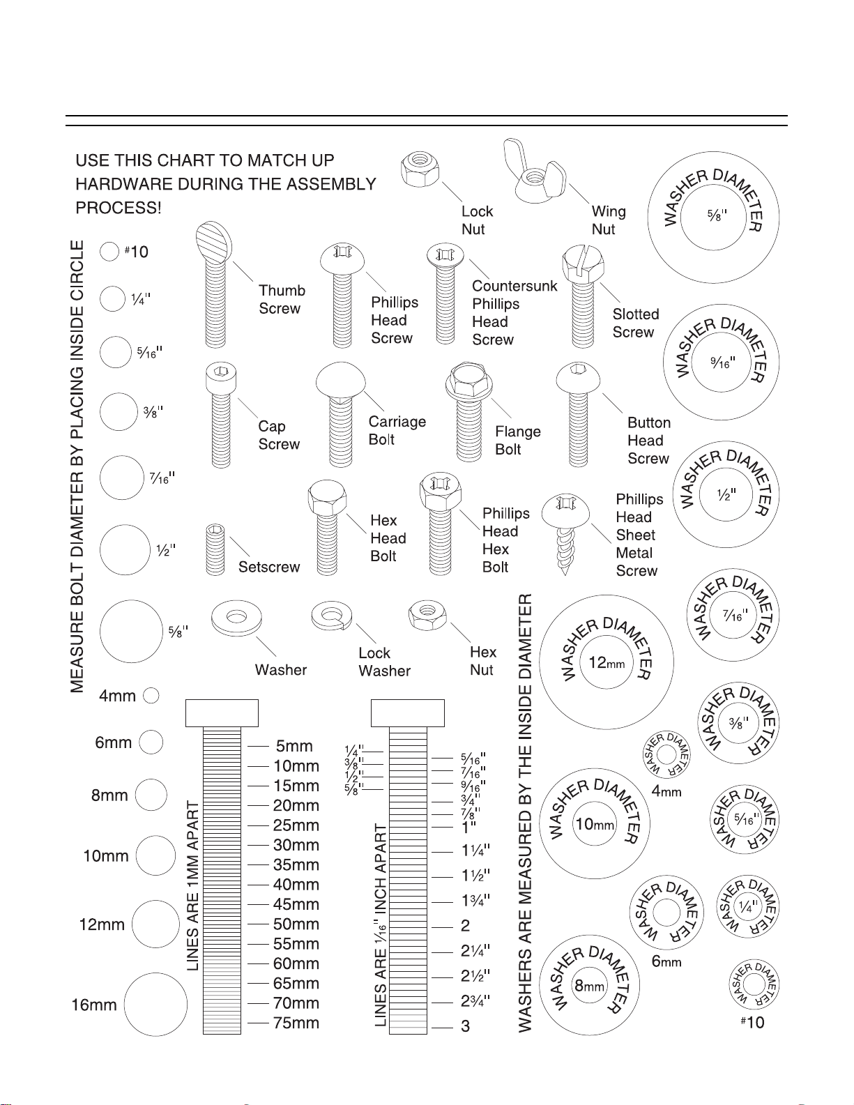
Hardware Recognition Chart ....................................................................................................16
Clean Up ..................................................................................................................................17
Site Considerations ..................................................................................................................17
Removing Resaw from Crate Pallet..........................................................................................18
Mounting Resaw to the Floor....................................................................................................19
Installing & Tensioning Blade....................................................................................................19
Adjusting Blade Guides ............................................................................................................21
Connecting to Dust Collector ....................................................................................................23
Connecting to Power Source ....................................................................................................23
Test Run....................................................................................................................................24
SECTION 6: OPERATIONS............................................................................................................25
Operation Safety ......................................................................................................................25
Stock Preparation......................................................................................................................25
Conveyor Controls ....................................................................................................................26
Setting Blade Height ................................................................................................................27
Calibrating Digital Display ........................................................................................................27
Setting Blade Memory Function................................................................................................28
Resawing ..................................................................................................................................28
Blade Information ......................................................................................................................29
SECTION 7: MAINTENANCE ........................................................................................................31
Cleaning ....................................................................................................................................31
Miscellaneous............................................................................................................................31
V-Belts ......................................................................................................................................31
Bearings ....................................................................................................................................31
Greasing....................................................................................................................................32
Hydraulic Fluid Schedule ..........................................................................................................33
Hydraulic System Minor Service ..............................................................................................33
Hydraulic System Major Service ..............................................................................................35
Maintenance Log ......................................................................................................................36

SECTION 8: SERVICE ADJUSTMENTS........................................................................................37
About Service............................................................................................................................37
Adjusting Lower Blade Guides..................................................................................................37
Adjusting V-Belt Tension ..........................................................................................................38
Replacing V-Belts......................................................................................................................39
Adjusting Main Conveyor Table ................................................................................................40
Tracking Conveyors ..................................................................................................................41
Replacing Conveyors ................................................................................................................42
Blade Tracking and Wheel Alignment ......................................................................................44
Service Log ..............................................................................................................................47
SECTION 9: REFERENCE INFO....................................................................................................48
Aftermarket Accessories ..........................................................................................................48
Machine Data Sheet ..............................................................................................................49
Parts Breakdown and Parts List................................................................................................50
Troubleshooting ........................................................................................................................70
Wiring Diagrams........................................................................................................................71
Warranty and Returns ..............................................................................................................74
G0504 16" Horizontal Resaw Bandsaw -3-
5. KEEP CHILDREN AND VISITORS
AWAY. All children and visitors should be
kept at a safe distance from work area.
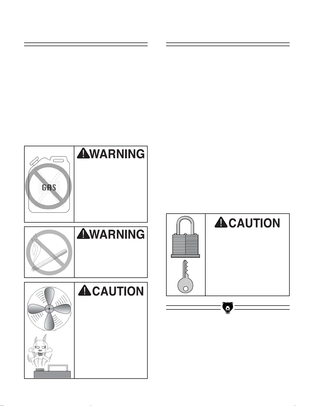
6. MAKE WORKSHOP CHILD PROOF with
padlocks, master switches, or by removing starter keys.
7. DO NOT FORCE TOOL. It will do the job
better and safer at the rate for which it
was designed.
8. USE RIGHT TOOL. DO NOT force tool or
attachment to do a job for which it was not
designed.
1. KEEP GUARDS IN PLACE and in working
order.
2. REMOVE ADJUSTING KEYS AND
WRENCHES. Form habit of checking to
see that keys and adjusting wrenches are
removed from tool before turning on.
3. KEEP WORK AREA CLEAN. Cluttered
areas and benches invite accidents.
4. DO NOT USE IN DANGEROUS ENVIRONMENT. DO NOT use power tools in
damp or wet locations, or where any flammable or noxious fumes may exist. Keep
work area well lighted.
For Your Own Safety, Read Instruction
Manual Before Operating this Equipment
Indicates an imminently hazardous situation which, if not avoided,
WILL result in death or serious injury.
Indicates a potentially hazardous situation which, if not avoided,
COULD result in death or serious injury.
Indicates a potentially hazardous situation which, if not avoided,
MAY result in minor or moderate injury. It may also be used to alert
against unsafe practices.
This symbol is used to alert the user to useful information about
proper operation of the equipment.
The purpose of safety symbols is to attract your attention to possible hazardous conditions.
This manual uses a series of symbols and signal words which are intended to convey the level
of importance of the safety messages. The progression of symbols is described below.
Remember that safety messages by themselves do not eliminate danger and are not a substitute for proper accident prevention measures.
NOTICE
Safety Instructions for Power Tools
SECTION 1: SAFETY
-4- G0504 16" Horizontal Resaw Bandsaw
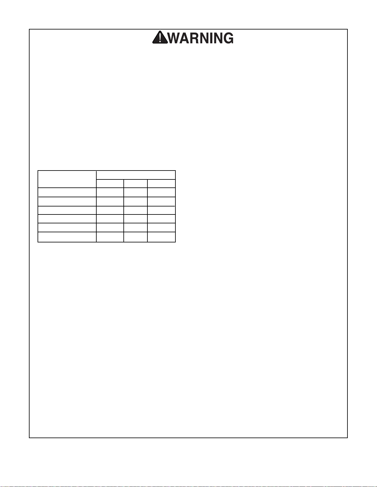
9. USE PROPER EXTENSION CORD. Make
sure your extension cord is in good condition. Conductor size should be in accordance with the chart below. The amperage
rating should be listed on the motor or tool
nameplate. An undersized cord will cause
a drop in line voltage resulting in loss of
power and overheating. Your extension
cord must also contain a ground wire and
plug pin. Always repair or replace extension cords if they become damaged.
Minimum Gauge for Extension Cords
10. WEAR PROPER APPAREL. DO NOT
wear loose clothing, gloves, neckties,
rings, bracelets, or other jewelry which may
get caught in moving parts. Non-slip
footwear is recommended. Wear protective
hair covering to contain long hair.
11. ALWAYS USE SAFETY GLASSES. Also
use face or dust mask if cutting operation is
dusty. Everyday eyeglasses only have impact
resistant lenses, they are NOT safety glasses.
12. SECURE WORK.Use clamps or a vise to hold
work when practical. It is safer than using your
hand and frees both hands to operate tool.
13. DO NOT OVERREACH. Keep proper foot-
ing and balance at all times.
14. MAINTAIN TOOLS WITH CARE. Keep
tools sharp and clean for best and safest
performance. Follow instructions for lubricating and changing accessories.
Safety Instructions for Power Tools
15. USE RECOMMENDED ACCESSORIES.
Consult the instruction manual for recommended accessories. The use of improper
accessories may cause risk of injury.
16. REDUCE THE RISK OF UNINTENTIONAL STARTING. On machines with mag-
netic contact starting switches there is a
risk of starting if the machine is bumped or
jarred. Always disconnect from power
source before adjusting or servicing. Make
sure switch is in OFF position before reconnecting.
17. MANY WOODWORKING TOOLS CAN
“KICKBACK” THE WORKPIECE toward
the operator if not handled properly. Know
what conditions can create “kickback” and
know how to avoid them. Read the manual
accompanying the machine thoroughly.
18. CHECK DAMAGED PARTS. Before fur-
ther use of the tool, a guard or other part
that is damaged should be carefully
checked to determine that it will operate
properly and perform its intended function.
Check for alignment of moving parts, binding of moving parts, breakage of parts,
mounting, and any other conditions that
may affect its operation. A guard or other
part that is damaged should be properly
repaired or replaced.
19. NEVER LEAVE TOOL RUNNING UNATTENDED. TURN POWER OFF. DO NOT
leave tool until it comes to a complete stop.
20. NEVER OPERATE A MACHINE WHEN
TIRED, OR UNDER THE INFLUENCE OF
DRUGS OR ALCOHOL. Full mental alert-
ness is required at all times when running
a machine.
21. NEVER ALLOW UNSUPERVISED OR
UNTRAINED PERSONNEL TO OPERATE THE MACHINE. Make sure any
instructions you give in regards to the
operation of the machine are approved,
correct, safe, and clearly understood.
LENGTH
AMP RATING 25ft 50ft 100ft
0-6 16 16 16
7-10 16 16 14
11-12 16 16 14
13-16 14 12 12
17-20 12 12 10
21-30 10 10 No

G0504 16" Horizontal Resaw Bandsaw -5-
Additional Safety Instructions for Bandsaws
9. THIS MACHINE IS NOT DESIGNED TO
CUT METAL or other material except
wood.
10. DO NOT MANUALLY STOP OR SLOW
BLADE after turning the saw off. Allow it to
come to a complete stop before you leave
it unattended.
11. ALL INSPECTIONS, ADJUSTMENTS,
AND MAINTENANCE MUST BE DONE
WITH THE POWER OFF and the circuit
breaker shut off. Wait for all moving parts
to come to a complete stop.
12. HABITS – GOOD AND BAD – ARE
HARD TO BREAK. Develop good habits
in your shop and safety will become second-nature to you.
13. IF AT ANY TIME YOU ARE EXPERIENC-
ING DIFFICULTIES PERFORMING THE
INTENDED OPERATION, STOP USING
THE BANDSAW! Then contact our service
department or ask a qualified expert how
the operation should be performed.
14. MAKE SURE BLADE IS PROPERLY
TENSIONED BEFORE OPERATING
MACHINE.
15. KEEP LOOSE CLOTHING AND LONG
HAIR AWAY FROM MOVING CONVEYORS!
1. DO NOT OPERATE WITH DULL OR
BADLY WORN BLADES. Dull blades
require more demand on the motor and are
less likely to cut precisely. Inspect blades
before each use.
2. NEVER POSITION FINGERS OR
THUMBS IN LINE WITH THE CUT.
Serious personal injury could occur.
3. DO NOT OPERATE THIS BANDSAW
WITHOUT WHEEL GUARDS, PULLEY
GUARDS, AND BLADE GUARDS IN
PLACE.
4. WHEN REPLACING BLADES, make sure
the teeth face toward the front of the saw.
5. CUTS SHOULD ALWAYS BE FULLY
SUPPORTED against the side of the con-
veyor table and by the pressure rollers.
6. DO NOT BACK WORKPIECE AWAY from
the blade while the saw is running. If you
need to back the work out, stop the bandsaw and wait for the blade to stop. DO NOT
twist or put excessive stress on blade while
backing work away.
7. BLADE SHOULD BE RUNNING AT FULL
SPEED before beginning a cut.
8. ALWAYS FEED STOCK EVENLY AND
SMOOTHLY. DO NOT change conveyor
speeds during a cut.
No list of safety guidelines can be complete. Every shop environment is different.
Always consider safety first, as it applies to
your individual working conditions. Use
this and other machinery with caution and
respect. Failure to do so could result in
serious personal injury, damage to equipment, or poor work results.
Like all machines there is danger associated with the Model G0504. Accidents are frequently caused by lack of familiarity or failure to pay attention. Use this machine with
respect and caution to lessen the possibility of operator injury. If normal safety precautions are overlooked or ignored, serious
personal injury may occur.

-6- G0504 16" Horizontal Resaw Bandsaw
Additional Safety Instructions for Hydraulics
4. STOP THE MACHINE IF YOU NOTICE A
HYDRAULIC LEAK. Allowing the
machine to continue running with a leak
may increase the hazard of the situation.
5. DEPRESSURIZE THE HYDRAULIC
SYSTEM BEFORE ATTEMPTING TO
ADJUST ANY HYDRAULIC LINES OR
FITTINGS. Stop the resaw, open the con-
veyor speed valves, and make sure the
pressure gauge reads 0 PSI.
6. DEPRESSURIZE THE HYDRAULIC
SYSTEM BEFORE ATTEMPTING ANY
MAINTENANCE OR SERVICE. Stop the
resaw, open the conveyor speed valves,
and make sure the pressure gauge reads
0 PSI.
7. REGULARLY INSPECT AND PERFORM THE PROPER MAINTENANCE
ON THE HYDRAULIC SYSTEM. A well-
maintained hydraulic system will have
much fewer problems and hazards than a
neglected system.
8. MAKE SURE ANY HYDRAULIC SYSTEM MAINTENANCE IS PERFORMED
IN A CLEAN AND DUST-FREE WORK
AREA. Remove any sawdust, grime or
water from hydraulic system openings or
components before maintenance. Always
use lint-free rags when wiping components.
9. ONLY USE HIGH PRESSURE
HYDRAULIC HOSE AND STEEL
HYDRAULIC FITTINGS WHEN
REPLACING COMPONENTS IN THE
HYDRAULIC SYSTEM. DO NOT use
brass or aluminum.
1. BE FAMILIAR WITH THE HAZARDS OF
HYDRAULIC INJECTION INJURIES.
• Leaking hydraulic fluid may have
enough pressure to penetrate skin.
Never use your hands to check for
suspected hydraulic leaks.
• Hydraulic fluid that is injected into
skin is a medical emergency that
may cause infection, disability,
amputation or death.
• The average injection injury may
be a small wound that has barely
broken the skin. DO NOT be
fooled by this type of injury.
Immediately get to an emergency
medical facility!
•Minimizing the time between the
injury and when the injected material is removed is critical to minimizing the seriousness of the
injury.
2. USE A PIECE OF CARDBOARD TO
CHECK FOR SUSPECTED HYDRAULIC
LEAKS. Pressurized hydraulic fluid may
cause injection injuries and can be
extremely hot. Never use your hands to
check for suspected hydraulic leaks.
3. PROTECT YOUR EYES AROUND
HYDRAULIC SYSTEMS. Safety glasses
may not always protect your eyes from
hot, pressurized fluid. The best way to
protect yourself is to stay away from leaks
until you can depressurize the system.
G0504 16" Horizontal Resaw Bandsaw -7-
Grizzly Industrial, Inc. is proud to offer the Model
G0504 16" Horizontal Resaw Bandsaw. This
resaw bandsaw is part of Grizzly’s growing family of fine woodworking machinery. When used
according to the guidelines stated in this manual,
you can expect years of trouble-free, enjoyable
operation, and proof of Grizzly’s commitment to
customer satisfaction.
We are also pleased to provide this manual for
the Model G0504. It was written to guide you
through assembly, review safety considerations,
and cover general operating procedures. It represents our latest effort to produce the best documentation possible.
If you have any comments or criticisms that you
feel we should address in our next printing,
please write to us at:
Grizzly Industrial, Inc.
C
⁄O Technical Documentation
P.O. Box 2069
Bellingham, WA 98227
Most important, we stand behind our machines.
We have excellent regional service departments
at your disposal should the need arise.
If you have any service questions or parts
requests, please call or write to us at the location
listed below.
Grizzly Industrial, Inc
1203 Lycoming Mall Circle
Muncy, PA 17756
Phone:(570) 546-9663
Fax:(800) 438-5901
E-Mail: techsupport@grizzly.com
Web Site: http://www.grizzly.com
The specifications, drawings, and photographs
illustrated in this manual represent the Model
G0504 as supplied when the manual was prepared. However, owing to Grizzly’s policy of continuous improvement, changes may be made at
any time with no obligation on the part of Grizzly.
For your convenience, we always keep current
Grizzly manuals available on our website at
www.grizzly.com
. Any updates to your machine
will be reflected in these manuals as soon as they
are complete.
If you DO NOT read this
entire manual before
operating the machine,
you will greatly increase
your chances of serious
personal injury. To protect yourself, read and
understand this entire
manual!
Commentary
SECTION 2: GENERAL INFORMATION
-8- G0504 16" Horizontal Resaw Bandsaw
A fire may occur if your particular electrical
configuration does not comply with local
and state codes. The best way to ensure
compliance is to check with your local
municipality or a licensed electrician.
Your Shop Circuit Capacity
Always check to see if the wires in your circuit are
capable of handling the amperage draw from
your machine, as well as any other machines that
could be operating on the same circuit. If you are
unsure, consult a qualified electrician.
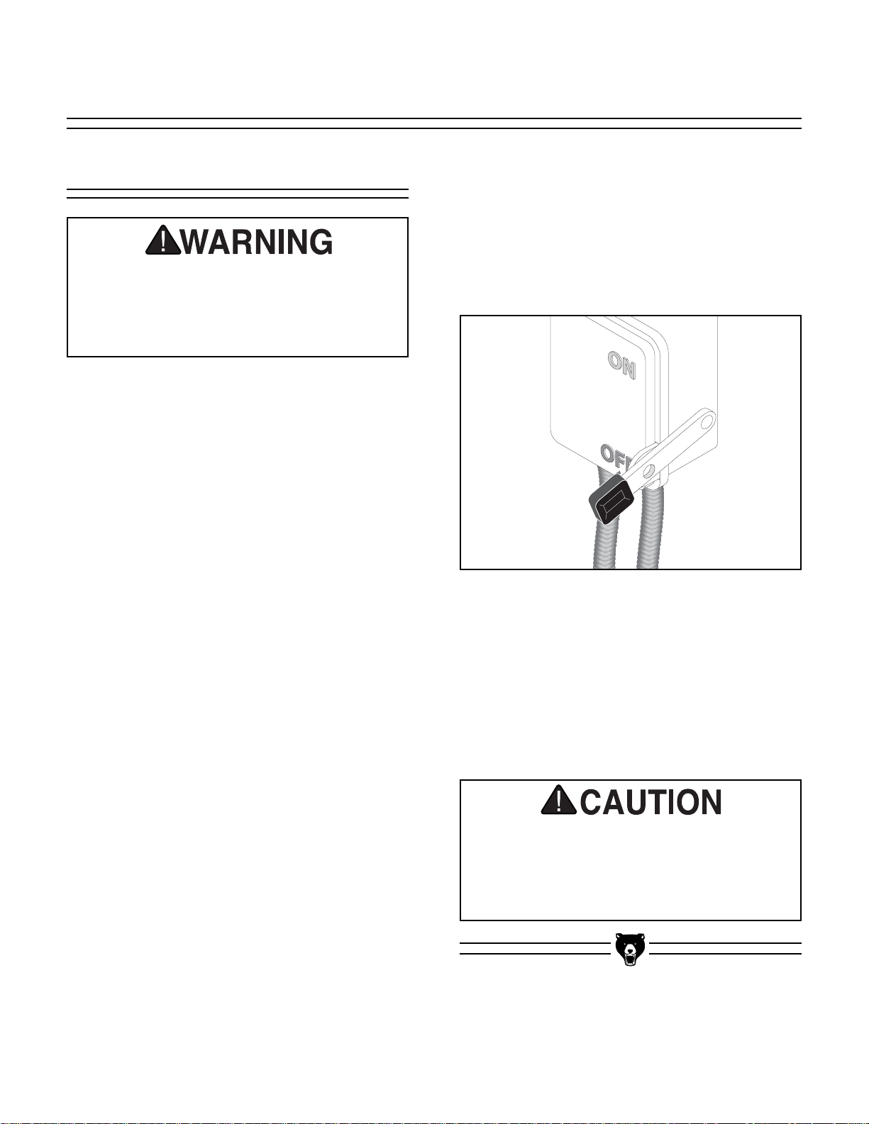
Figure 1. A power disconnect is preferable to
high current plugs and receptacles.
Serious personal injury could occur if you
connect your machine to the power source
before you have completed the setup
process. DO NOT connect the machine to
the power source until instructed to do so.
Wiring
The Model G0504 is prewired for 220V operation.
Amperage Draw
The Model G0504 has a 25 HP main motor and a
1
⁄4 HP elevation motor that will draw the following
amps at 3-phase 220V:
Main Motor ............................................60 Amps
Elevation Motor ....................................1.5 Amps
Circuit Breaker Requirements
Install your bandsaw on a dedicated circuit to
reduce the possibility of overloading the circuit
and tripping the circuit breaker. If the circuit
breaker trips and the circuit is of the correct load
capacity, have the circuit inspected by qualified
electrician. Never use a larger circuit breaker
than stated below, or you will increase the risk of
fire.
Circuit Breaker ........................................70 Amp
Minimum Cord Requirements
For 220V 3-phase operation, use the following
type of cord:
Cord................................................3 pole, 4 wire
Gauge ................................................................4
220V 3-Phase
SECTION 3: CIRCUIT REQUIREMENTS
Connection Type
Because of the high amperage draw from this
machine, we recommend that you hardwire it
directly to your circuit breaker and install a lock-
ing shut-off lever (see Figure 1) near the
machine as a way to quickly disconnect the
power. We DO NOT recommend using an extension cord with this machine.
G0504 16" Horizontal Resaw Bandsaw -9-
440V 3-Phase
Your Shop Circuit Capacity
Always check to see if the wires in your circuit are
capable of handling the amperage draw from
your machine, as well as any other machines that
could be operating on the same circuit. If you are
unsure, consult a qualified electrician.
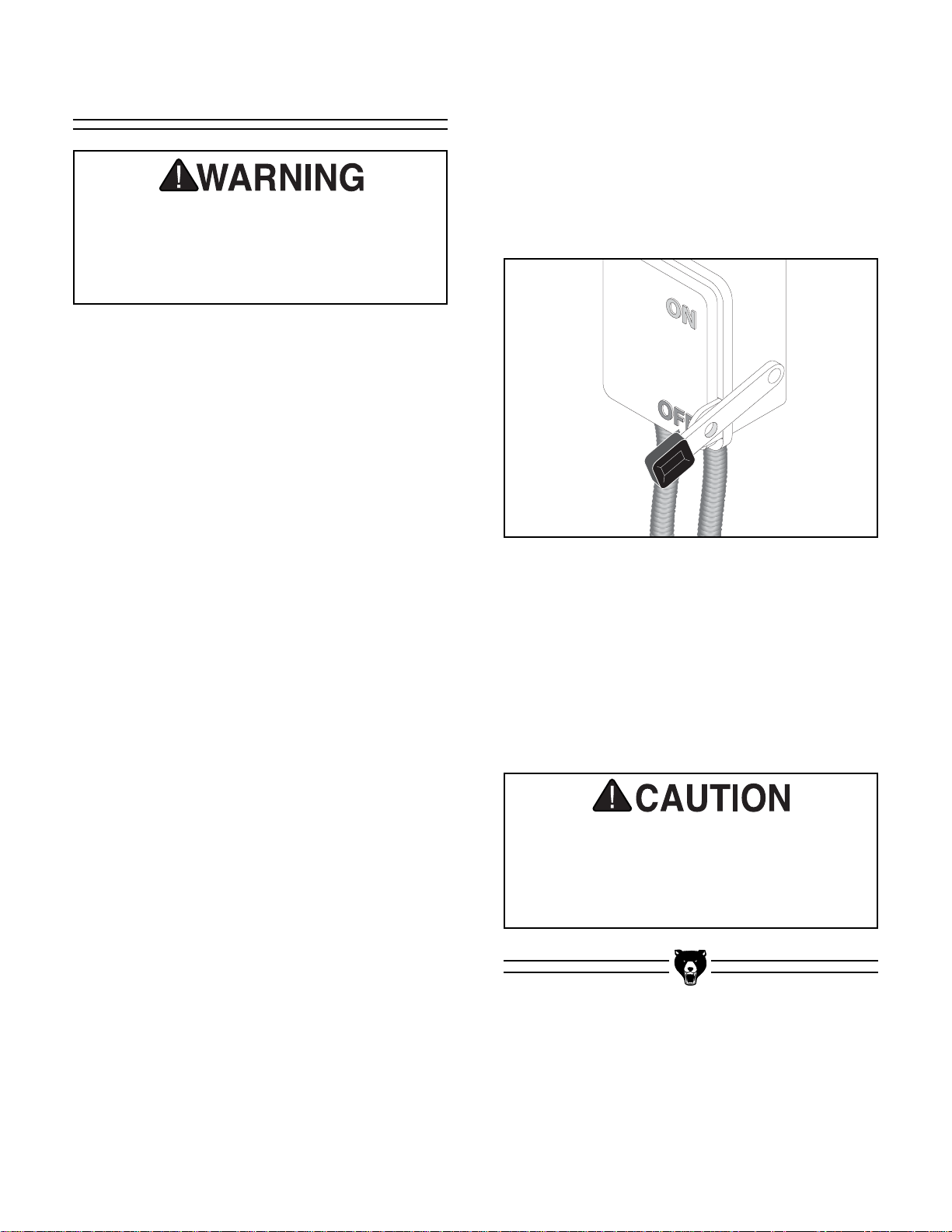
Figure 2. A power disconnect is preferable to
high current plugs and receptacles.
Serious personal injury could occur if you
connect your machine to the power source
before you have completed the setup
process. DO NOT connect the machine to
the power source until instructed to do so.
Wiring
The Model G0504 is prewired for 220V 3-phase,
but can be rewired to 440V operation. If you
decide to rewire the Model G0504 to 440V, you
must follow the instructions on pages 10-11 that
are titled “Converting to 440V.”
Amperage Draw
The Model G0504 has a 25 HP 3-phase main
motor and a
1
⁄4 HP 3-phase elevation motor that
will draw the following amps at 440V:
Main Motor ............................................30 Amps
Elevation Motor ..................................0.75 Amps
Circuit Breaker Requirements
Install your bandsaw on a dedicated circuit to
reduce the possibility of overloading the circuit
and tripping the circuit breaker. If the circuit
breaker trips and the circuit is of the correct load
capacity, have the circuit inspected by qualified
electrician. Never use a larger circuit breaker
than is stated below, or you will increase the risk
of fire.
Circuit Breaker ........................................40 Amp
Minimum Cord Requirements
For 440V operation, use the following type of
cord:
Cord................................................3 pole, 4 wire
Gauge ................................................................8
A fire may occur if your particular electrical
configuration does not comply with local
and state codes. The best way to ensure
compliance is to check with your local
municipality or a licensed electrician.
Connection Type
Because of the high amperage draw from this
machine, we recommend that you hardwire it
directly to your circuit breaker and install a lock-
ing shut-off lever (see Figure 2) near the
machine as a way to quickly disconnect the
power. We DO NOT recommend using an extension cord with this machine.
-10- G0504 16" Horizontal Resaw Bandsaw
Converting the Model G0504 to 440V operation
consists of 1) wiring the voltage transformer, 2)
rewiring the main motor and the elevation motor,
and 3) changing the main over-load relay with the
relay included in the Grizzly Model G0504, 440V
Conversion Kit (item #P0504919).
To convert the Model G0504 to 440V:
1. Disconnect the resaw from the power
source!
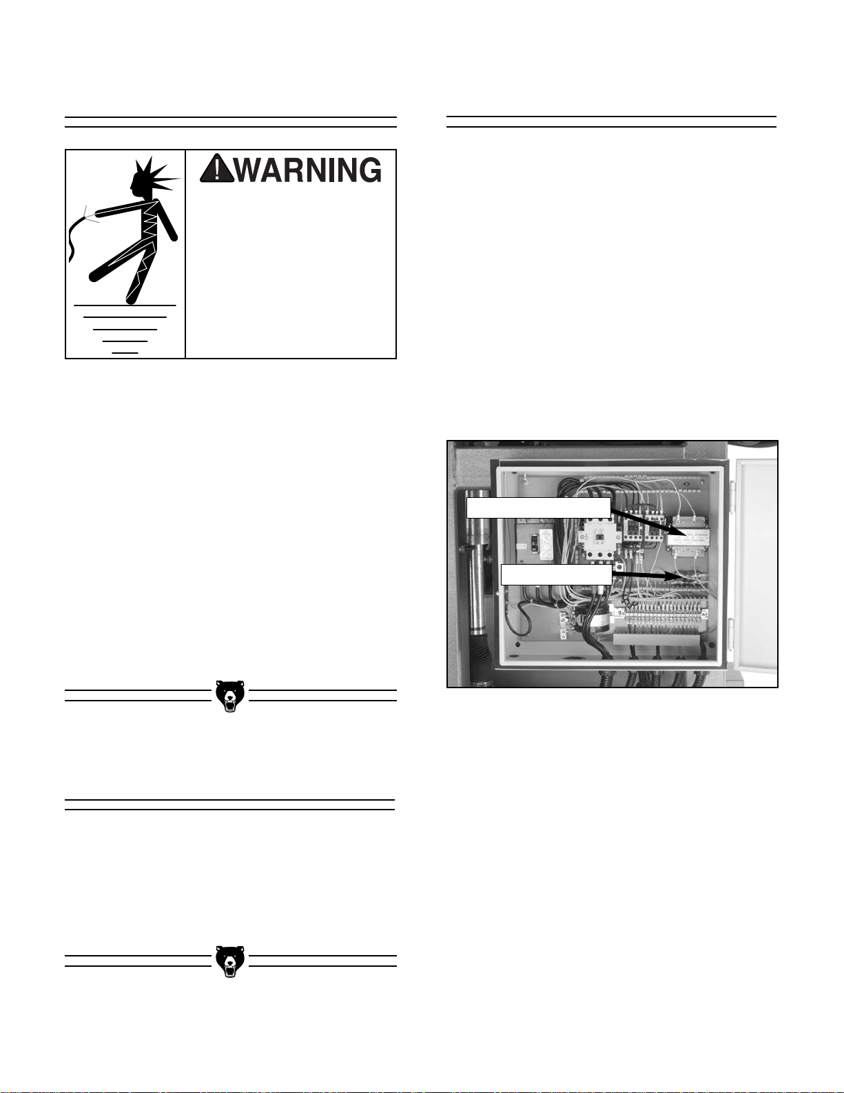
2. Open the electrical box and locate the volt-
age transformer and the fuse terminals
shown in Figure 3.
Figure 3. Inside of electrical box.
Voltage Transformer
Fuse Terminals
In the event of an electrical malfunction or breakdown, grounding provides a path of least resistance for electric current to reduce the risk of
electric shock. This machine must be equipped
with an electric cord that has an equipment
grounding conductor. This conductor must be
grounded in accordance with all local codes and
ordinances.
Improper connections of the electrical-grounding
conductor can result in the risk of electric shock.
Check with a qualified electrician or one of our
service personnel if the grounding instructions
are not completely understood, or if you are in
doubt as to whether the machine is properly
grounded.
Electrocution or fire could
result if this machine is
not grounded correctly.
Make sure all electrical circuits are grounded before
you connect them to the
machine. DO NOT use the
Model G0504 if it is not
grounded.
Because of the high amperage draw from this
machine, we do not recommend the use of extension cords. Instead, position your equipment near
installed wiring to eliminate the need for extension cords.
Converting to 440V
Extension Cords
Grounding
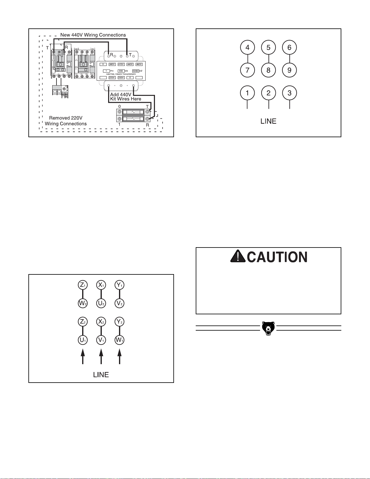
3. Remove the T and R wires from the fuse ter-
minals and connect them to the terminals on
the upper part of the voltage transformer, at
the location shown in Figure 4; then attach
the wires included with 440V conversion kit
from the fuse terminals to the terminals on
the lower part of the voltage transformer,
also as shown in Figure 4. Note—Make sure
the wires are routed through the wiring duct
to properly secure them and minimize fire
hazards.
G0504 16" Horizontal Resaw Bandsaw -11-
Figure 4. Wiring connections for 440V
conversion.
4. Remove the wiring caps on the main and ele-
vation motors.
5. Wire the main and elevation motors as
shown on the diagrams on the inside of each
motor wire cover. Note—The circled refer-
ences on the diagrams represent labels on
the wires. Also, Figures 5 & 6 below have
been provided for your reference and are
current at the time that this manual was written. However, always use the diagram on the
wire cover that comes with your motor!
Figure 5. Main motor 440V wiring.
Figure 6. Elevation motor 440V wiring.
6. Replace the main relay (RH-65/55A) with the
relay from kit (RH-35/30A) and set the dial to
“31.”
7. Replace any wire duct covers and motor
caps you might have removed during this
procedure, and close the electrical box door.
8. Call a licensed electrician to inspect your
work before test running the machine.
A fire may occur if your conversion job does
not comply with local and state codes.
Ensure your wiring conversion is inspected
and approved by a licensed electrician
before connecting your machine to the
power source.
-12- G0504 16" Horizontal Resaw Bandsaw
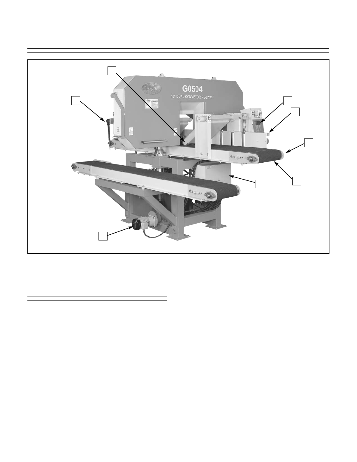
1. Infeed Pressure Rollers—Maintain down-
ward pressure on the board to keep it sturdy
during cutting.
2. Blade Tensioner—Provides a mechanical
means for properly tightening the blade.
3. Head Elevation Motor—Responsible for
moving the head (the part of the saw that
contains the wheels and blade) up or down
as needed.
4. Electrical Control Box—Main area for
wiring, rewiring, and changing the fuses.
Should never be opened when the machine
is connected to the power source!
5. Infeed Conveyor—Moves the board through
the bandsaw blade during cutting.
6. Infeed Conveyor Speed Dial—Controls the
conveyor belt feed rate.
7. Infeed Conveyor Engagement Lever—
Allows the operator to stop and start the
infeed conveyor while the blade is moving.
8. Control Panel—The part of the resaw where
the operator can control the starting and
stopping of the motor, the various height
changes, and the calibration of the blade
height to the conveyor. The control panel
also houses a load meter that allows the
operator to monitor the load being placed on
the resaw during operation. For more details,
see page 14.
Figure 7. Main view of machine features and controls.
2
3
5
6
4
7
8
1
Main Features
SECTION 4: MACHINE FEATURES
G0504 16" Horizontal Resaw Bandsaw -13-
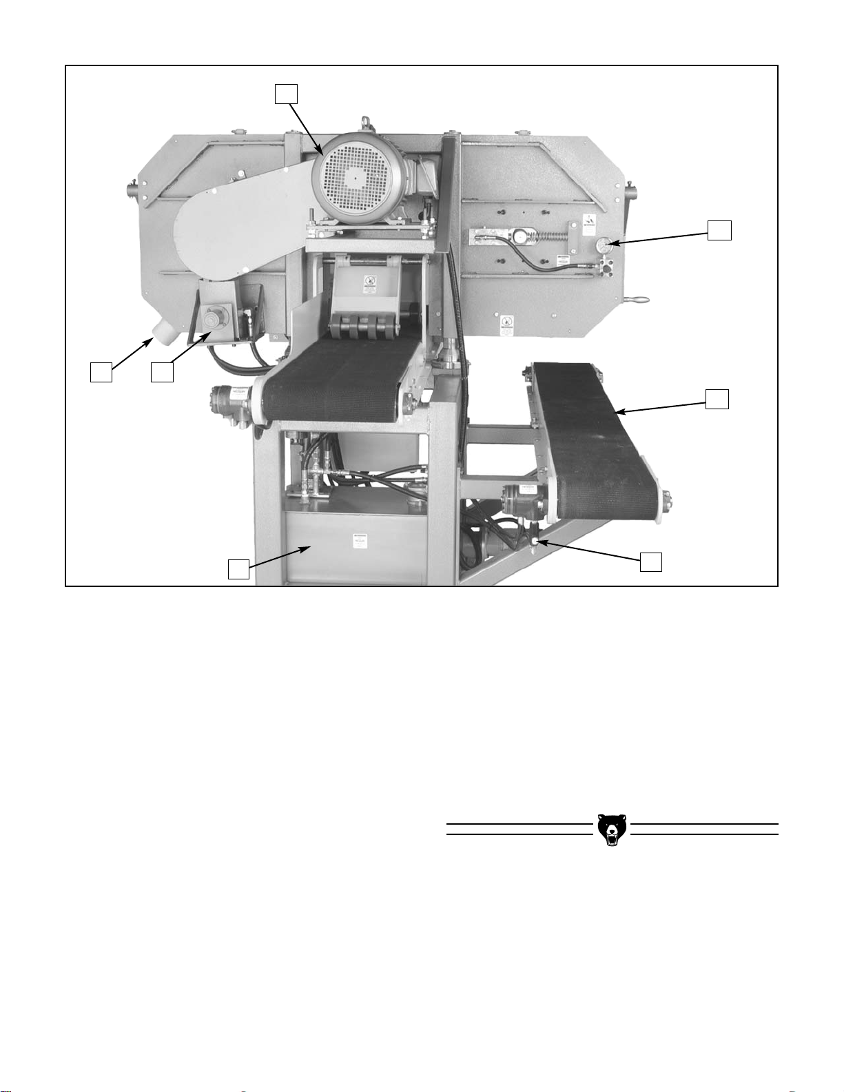
9. Main Motor—Powers the saw wheels for
blade movement and drives the hydraulic
pump for conveyor movement.
10. 4" Dust Port—Allows the resaw to be con-
nected to a dust collection system.
11. Hydraulic Pump—Creates hydraulic oil flow
which drives the conveyor motors.
12. Hydraulic Tank—Holds and cools the
hydraulic fluid for the hydraulic system.
13. Return Conveyor Speed Dial—Controls the
speed that the return conveyor belt moves.
14. Return Conveyor—Allows the person
receiving the newly cut board to return it to
the operator without walking around the saw.
15. Blade Tension Gauge—Shows the current
blade tension.
Figure 8. Main view of machine features and controls.
10 11
12
13
15
14
9
-14- G0504 16" Horizontal Resaw Bandsaw
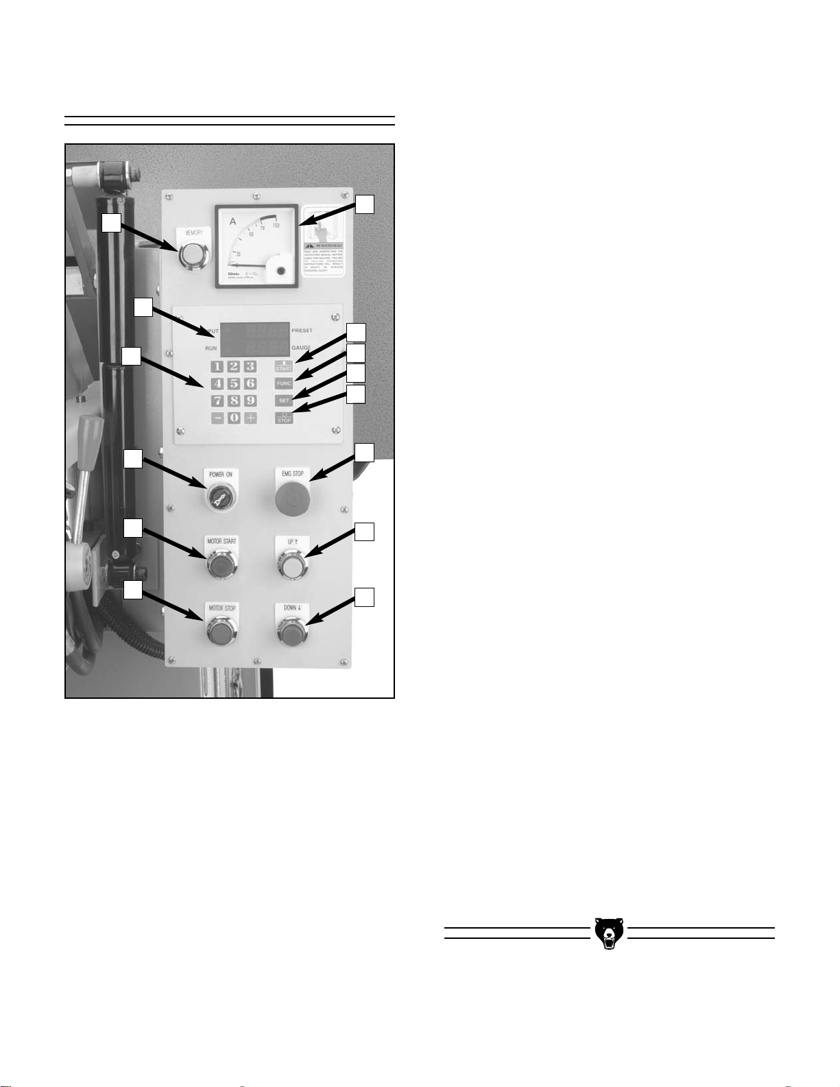
Control Panel
A. Memory Button—Moves blade to a preset
height change. For example, if you want to
produce multiple
1
⁄4" boards from a 5" board,
you can set the memory to X inches (X=
1
⁄4" +
your blade kerf). After every cut, the head will
automatically move down X inches when you
press the memory button. You can then
repeat this procedure until the 5" board is
reduced to the last
1
⁄4" that can be cut from
that board.
B. Display—Shows the distance from the con-
veyor belt to the blade. Also used to enter
and change settings, move blade height, and
program the memory function.
A
M
L
K
J
H
I
B
G
C
D
E
F
N
C. Keypad—Inputs height values.
D. POWER ON Switch—Engages power to the
control panel.
E. MOTOR START Button—Starts the main
motor, which is responsible for the blade and
conveyor movement.
F. MOTOR STOP Button—Stops the main
motor, blade, and conveyors.
G. DOWN Button—Moves the head (blade)
down toward the infeed conveyor.
H. UP Button—Moves the head (blade) up
toward the infeed conveyor.
I. EMG STOP Button—Cuts power to the
main motor to stop the blade and hydraulic
pump. (Caution—It takes approximately 30
seconds for the blade to come to a complete
stop.)
J. STOP Key—Stops the elevation motor from
its current movement.
K. SET Key—Calibrates the height of the blade
from the table, or can be used in combination
with the FUNC key to set the memory.
L. FUNC Key—Prepares the control panel for
special functions. Can be used in combina-
tion with the START key to manually type in
a numeric height on the keypad, or can be
used in combination with the SET key to set
the memory.
M. START Key—Moves the blade to the height
that is entered in the keypad. Must be used
in conjunction with the FUNC key.
N. Load Meter—Displays the current load
placed on the machine. The load meter is
used to determine the appropriate conveyor
feed rate for each species of wood and each
blade being used.
Figure 9. Control panel close-up.
G0504 16" Horizontal Resaw Bandsaw -15-
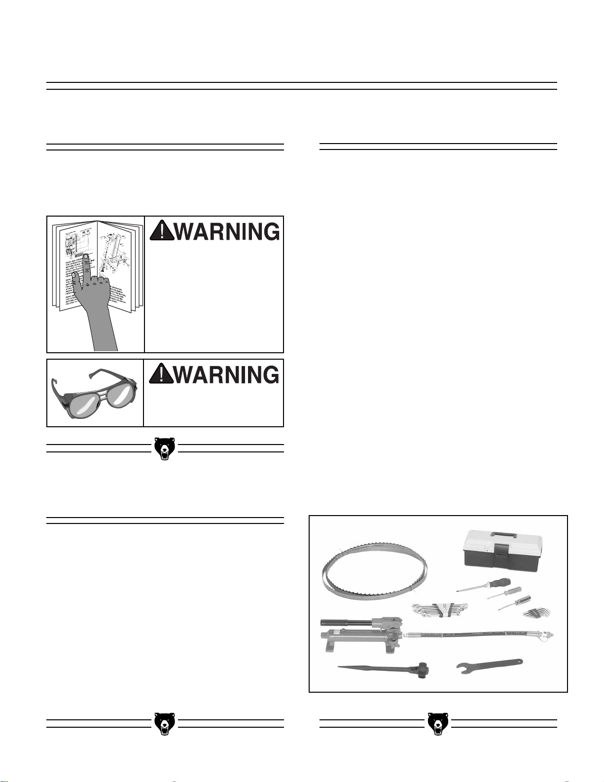
After all the parts have been removed from
the shipping crate, you should have:
• Resaw Bandsaw Machine
• Bandsaw Blade 180" x 1" x 0.035"
• Tool Box
• 10 Ton Hand Press Pump
•7 pc. Combination Wrench Set
—10, 12, 13, 14, 17, 19, 21 mm
•7 pc. Hex Wrench Set
—2.5, 3, 4, 5, 6, 8, 10 mm
• Phillips Head Screwdriver
• Flat Head Screwdriver
• Blade Tensioning Ratchet 21, 23 mm
• Adjustment Wrench 32 mm
• Wheel Cover Handle
• Spare Parts Hardware Bag
—Cap Screw (4) M10-1.25 x 30
—Cap Screw (4) M10-1.25 x 25
—Hex Bolt (4) M12-1.5 x 40
—Hex Nut (4) M12-1.5
In the event that any non-proprietary parts are
missing (e.g. nuts or washers), we would be glad
to replace them, or for the sake of expediency,
replacements can be obtained at your local hardware store.
The Model G0504 is shipped from the manufacturer in a carefully built crate. If you discover the
machine is damaged after you have signed for
delivery, please immediately call Customer
Service at (570) 546-9663 for advice.
Save the containers and all packing materials for
possible inspection by the carrier or its agent.
Otherwise, filing a freight claim can be difficult.
When you are completely satisfied with the condition of your shipment, you should inventory the
equipment from the shipping crate.
The purpose of this section is to guide you
through the required steps to get your machine
out of its crate and into operating condition.
Wear safety glasses during the entire set up
process!
This machine presents
serious injury hazards
to untrained users. Read
through this entire manual to become familiar
with the controls and
operations before starting the machine!
Figure 10. Piece inventory from packing crate.
Piece Inventory
Unpacking
About this Section
SECTION 5: SET UP
-16- G0504 16" Horizontal Resaw Bandsaw
Hardware Recognition Chart
G0504 16" Horizontal Resaw Bandsaw -17-
1. Floor Load: The Model G0504 represents a
large weight load (3300 lbs.) in a large footprint. Most commercial floors are suitable for
your machine. Some residential floors may
require additional build up to support both
the machine and operator.
2. Working Clearances: Consider existing and
anticipated needs, size of material to be
processed through each machine, and
space for auxiliary stands, work tables or
other machinery when establishing a location for your bandsaw.
3. Lighting and Outlets: Lighting should be
bright enough to eliminate shadow and prevent eye strain. Electrical circuits should be
dedicated or large enough to handle amperage requirements. Outlets should be located
near each machine so power or extension
cords are clear of high-traffic areas. Observe
local electrical codes for proper installation
of new lighting, outlets, or circuits.
Unsupervised children and
visitors inside your shop
could cause serious personal injury to themselves. Lock
all entrances to the shop
when you are away and DO
NOT allow unsupervised
children or visitors in your
shop at any time!
The unpainted surfaces are coated with a waxy
oil to protect them from corrosion during shipment. Remove this protective coating with a solvent cleaner or citrus-based degreaser such as
Grizzly’s G7895 Degreaser. To clean thoroughly,
some parts may need to be removed. For opti-
mum performance from your machine, make
sure you clean all moving parts or sliding
contact surfaces that are coated. Avoid chlo-
rine-based solvents as they may damage painted
surfaces should they come in contact. Always follow the manufacturer’s instructions when using
any type of cleaning product.
Gasoline and petroleum
products have low flash
points and could cause
an explosion or fire if
used to clean
machinery. DO NOT use
gasoline or petroleum
products to clean the
machinery.
Smoking near solvents
could ignite an explosion
or fire and cause serious
injury. DO NOT smoke
while using solvents.
Many of the solvents
commonly used to clean
machinery can be toxic
when inhaled or ingested. Lack of ventilation
while using these solvents could cause serious personal health risks
or fire. Take precautions
from this hazard by only
using cleaning solvents
in a well ventilated area.
Site ConsiderationsClean Up
-18- G0504 16" Horizontal Resaw Bandsaw
Removing Resaw
from Crate Pallet
To remove the resaw from the crate pallet:
1. Remove the lag bolts from the stand feet that
secure the resaw to the crate pallet.
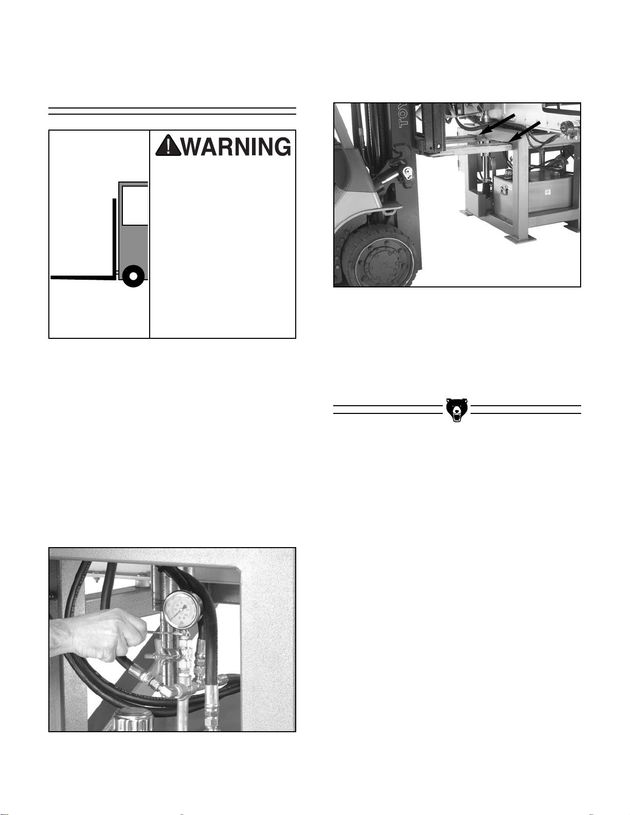
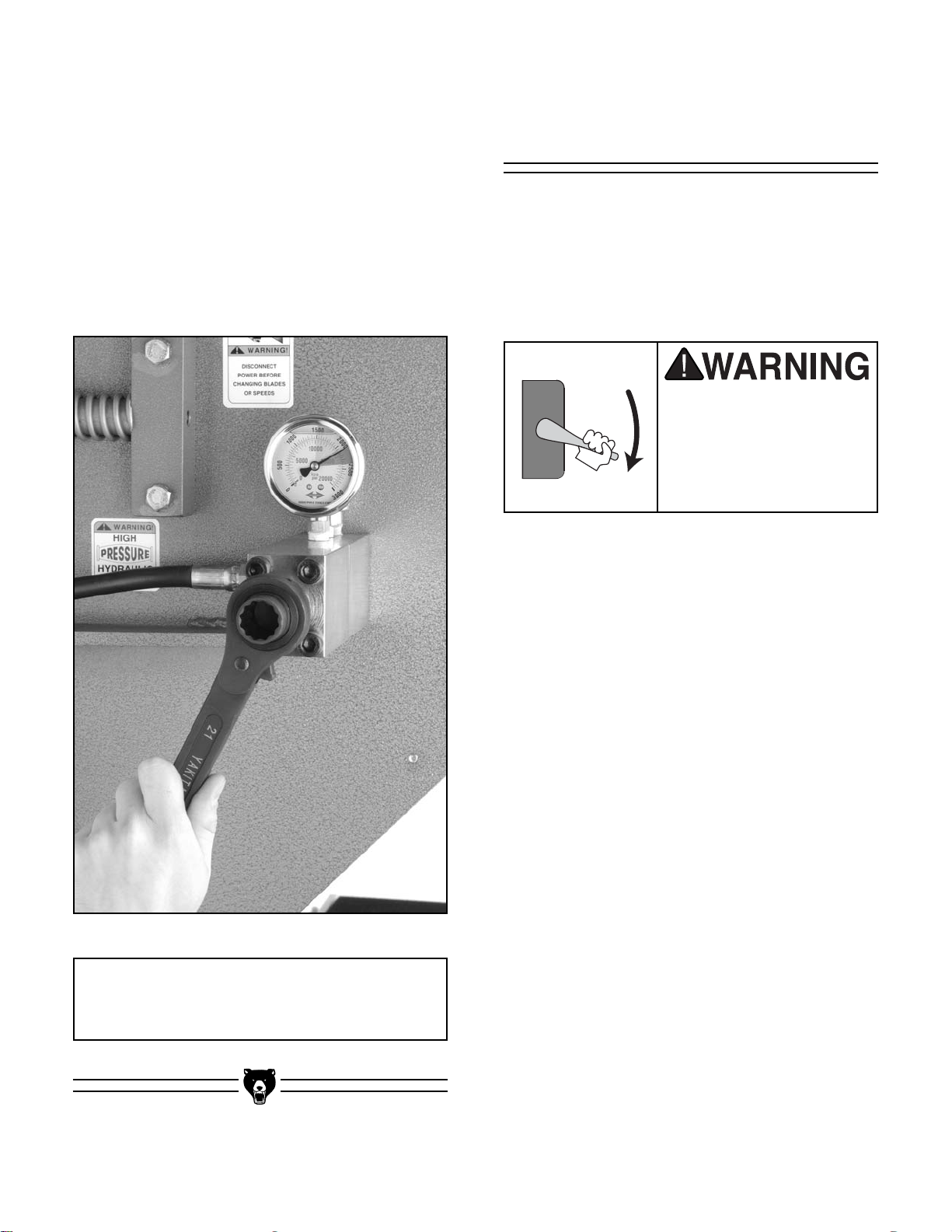
2. Using a wrench, remove the pressure gauge
that is located on top of the hydraulic reser-
voir as shown in Figure 11. Note—This step
is optional, but highly recommended to avoid
damaging the pressure gauge. If you do this
step, plug the opening on both the fitting and
the gauge to keep contamination out of the
hydraulic system.
Figure 12. Lifting points for moving the resaw
with a forklift.
Figure 11. Removing pressure gauge.
3. Using a forklift, lift the resaw from the frame
location shown in Figure 12, and move it to
your predetermined location.
The Model G0504 is a
heavy machine that
weighs approximately
3300 lbs. Serious personal injury may occur if
safe moving methods
are not followed. To be
safe, you will need assistance and power equipment when moving the
shipping crate and
removing the machine
from the crate.
4. After placing the resaw, make sure that you
remove any plugs and replace the hydraulic
pressure gauge before continuing to the next
step!
G0504 16" Horizontal Resaw Bandsaw -19-
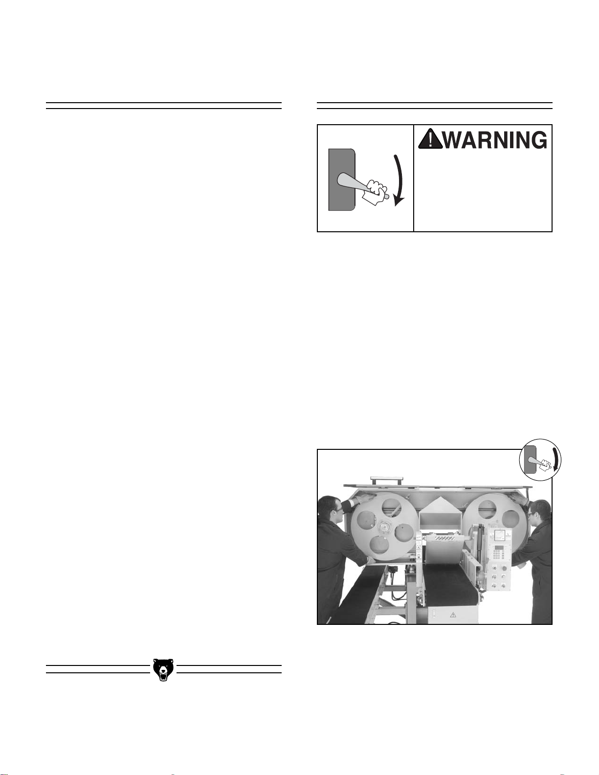
Blade installation can be done by one person but
is easiest if done with two people.
To install the blade:
1. Put on safety glasses and heavy leather
gloves.
2. Open the wheel cover to gain access to the
wheels.
3. Hold the blade from each side, and position
it in front of the wheels so the blade teeth are
facing the front of the machine, as shown in
Figure 13.
Although not required, we recommend that you
mount your new resaw machine to the floor.
Because this is an optional step and floor materials may vary, floor mounting hardware is not
included.
Note—The instructions below are given for a typ-
ical heavy-duty shop floor made of 6" thick concrete. Also, anchor studs may be substituted for
lag bolts, but they will stick out of the floor if you
decide to move your machine at a later point.
To mount the resaw machine to the floor:
1. For these steps you will need:
• Hammer drill
•
1
⁄2" punch
•
1
⁄2" hammer drill bit that is at least 6" long
• Twelve (12)
5
⁄16
" x 3" lag shields
• Twelve (12)
5
⁄16" x 4" lag bolts
• Twelve (12)
5
⁄16" extra-wide flat washers
• Hammer
2. Put on safety glasses and a dust mask
before starting!
3. Use the mounting holes in the resaw stand
feet to act as a guide for drilling into your
floor, and drill approximately 3
1
⁄2" deep into
the concrete floor.
4. Using compressed air and a vacuum hose,
remove the concrete dust from the newly
drilled holes.
5. Using the hammer and punch, pound the lag
shields into the concrete below the stand feet
and flush with the surface of the concrete.
6. Secure the resaw to the floor with the
5
⁄16" lag
bolts and washers.
These instructions present a serious injury hazard if done while the
machine is connected to
power. DO NOT connect
to power until instructed!
Figure 13. Positioning blade for installation.
Installing &
Tensioning Blade
Mounting Resaw to
the Floor
OFF
ON
ON
OFF
-20- G0504 16" Horizontal Resaw Bandsaw
Figure 14. Blade positioned between
blade guides.
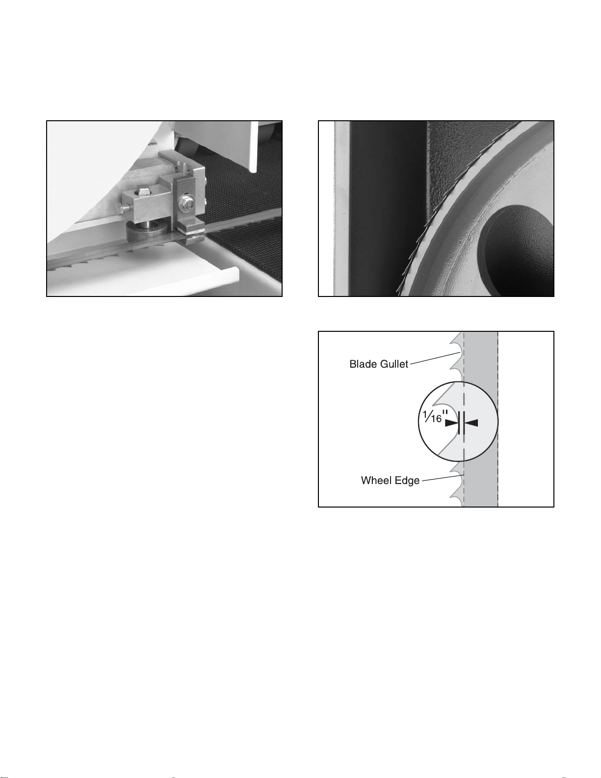
Figure 15. Blade positioned on wheel.
Figure 16. Illustration of proper blade position.
5. Position the blade on the wheels so that the
tooth gullet is approximately
1
⁄16" over the
edge of the wheel, as shown in Figure 15.
Also, see the blade illustration in Figure 16
for more details about this concept.
4. Carefully fit the blade over each wheel, and
position it between the blade guides as
shown in Figure 14. Make sure the teeth
point toward the right-hand side of the
machine, as you are facing the front.
G0504 16" Horizontal Resaw Bandsaw -21-
Each blade guide assembly consists of Guide
Blocks and a Support Bearing.
The blade guides keep the blade stable during
operation, so make sure they are properly adjusted before starting the bandsaw.
Adjusting Blade
Guides
These instructions present a serious injury hazard if attempted while the
machine is connected to
power. DO NOT connect
to power until instructed!
Guide Blocks
Each guide block consists of an upper and lower
ceramic block that stabilizes the blade from
up/down movement during operation.
The lower block is designed to remain in a fixed
position, and the upper block is designed to be
adjusted during each blade change. When the
machine is new, the lower block is set at the factory and should not need to be adjusted (see
Section 8: Service Adjustments for more informa-
tion about the lower guide). The upper block,
however, should be adjusted every time you
install a new blade or re-install an old blade.
Figure 17. Tensioning blade with tensioner.
6. Tighten the blade with the blade tensioner as
shown in Figure 17. Use the colored area on
the tension gauge as a proper tension guide
for your specific blade material.
Carbon Steel ......................................Yellow
Bi-metal ............................................Orange
Note—Always adjust the pressure to the low-
est rating of each colored area and then
increase tension as needed (blades stretch
as they warm up).
NOTICE
Always de-tension blade after use.
ON
OFF
-22- G0504 16" Horizontal Resaw Bandsaw
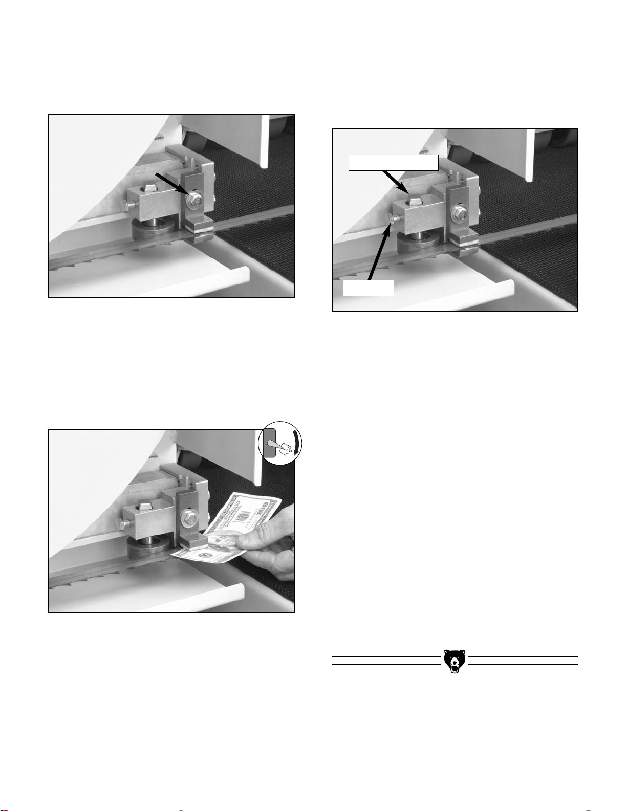
Figure 20. Support bearing components.
To adjust the support bearings:
1. Loosen the lock bolt approximately
1
⁄4 turn.
Note—If you loosen the lock bolt too much,
the support bearing will fall out of place.
2. Turn the adjustment shaft until the support
bearing is positioned approximately 0.016"
behind the back of the blade. Use a feeler
gauge or four thicknesses of a dollar bill to
check this.
3. Tighten the lock bolt, and repeat with the
other support bearing.
4. Test the adjustment of the support bearings
by spinning the wheels by hand, at full blade
tension, in the same direction of operation.
While you are spinning the wheels, the support bearings should not turn. (The support
bearings should only turn during cutting
operations.)
Support Bearing
The support bearing is positioned behind the
blade to brace it from pushing backwards during
a cut. Figure 20 shows the support bearing com-
ponents to clarify the adjustment instructions.
Figure 18. Guide block adjustment bolt.
Figure 19. Dollar bill between upper guide block
and blade.
2. Slide the upper guide block up, place a dol-
lar bill (as a quick gauge for 0.004" clearance) underneath the upper guide block,
then let the upper guide block slide down to
sandwich the dollar between the blade and
the upper guide block as shown in Figure
19.
3. Keep the dollar bill in place and tighten the
upper guide block.
4. Remove the dollar bill.
5. Repeat steps 1-4 with the blade guide on the
other side of the conveyor.
To adjust the upper guide block:
1. Loosen the guide block adjustment bolt
shown in Figure 18.
Adjustment Shaft
Lock Bolt
OFF
ON

G0504 16" Horizontal Resaw Bandsaw -23-
If you have performed all of the previous set up
instructions, you are ready to connect the resaw
to the power source. DO NOT connect the cord to
the power source until instructed.
To connect the resaw to the power source:
1. Read through Section 3: Circuit
Requirements to double-check that your
setup follows the safety and circuit requirements, and that the power cord you have
chosen meets the minimum requirements for
this machine.
2. Open the electrical panel on the machine.
3. Connect the cord to the machine circuit
breaker terminals shown in Figure 22.
Figure 22. Circuit breaker terminal.
Figure 21. Dust hose connected to dust port.
To be effective, the dust collection system that
you connect to the resaw must be able draw at
least 1000 CFM at the point where you connect
the hose to the resaw. Note—This number is an
approximation and has been provided for estimation purposes only.
To connect the resaw to a dust collector:
1. Attach a 4" dust hose to the dust port as
shown in Figure 21, and be sure to tighten
the hose clamp to ensure a snug fit.
4. Close and latch the electrical panel on the
machine.
5. Shut off the main power at the power
source circuit breaker and install the cord
to the disconnect switch.
Connecting to
Power Source
Connecting to Dust
Collector

-24- G0504 16" Horizontal Resaw Bandsaw
5. Press the UP and DOWN buttons to make
sure the resaw head moves in the proper
direction.
— If the resaw head moves in the opposite
direction as the buttons state, then the
power needs to be disconnected and the
power wires need to be switched at the
circuit breaker in the electrical box.
6. Once you have performed steps 1-4 and
everything is okay with the machine and set
up, press the MOTOR START button. As you
are standing in front of the machine, make
sure that the blade is moving from left to
right.
7. Press the conveyor lever forward to test the
conveyor belt. If the conveyor belt does not
turn after pushing the conveyor lever forward, adjust the conveyor speed knob.
— If any problems occur, press the EMG
STOP button. Investigate and correct the
problem before operating the machine
further. If you need help, refer to the troubleshooting section in the back of this
manual.
— If you cannot easily locate the source of
an unusual noise or vibration by yourself,
please contact our service department at
(570) 546-9663.
To test run the resaw:
1. Make sure the wheel cover is closed and all
tools or other objects are cleared away from
the resaw.
2. Put on safety glasses and make sure any
bystanders are out of the way and also wearing safety glasses.
3. Tension the blade.
4. Turn the POWER ON switch (shown in
Figure 23) clockwise.
Test Run
Before starting the resaw, make sure you
have performed the preceding assembly
and adjustment instructions, and you have
read through the rest of the manual and are
familiar with the various functions and safety issues associated with this machine.
Failure to follow this warning could result in
serious personal injury or even death!
Figure 23. POWER ON switch.

G0504 16" Horizontal Resaw Bandsaw -25-
NOTICE
The following section was designed to give
instructions on the basic operations of this
machine. However, it is in no way comprehensive of all of the machine’s applications.
WE STRONGLY RECOMMEND that you read
books, trade magazines, or get formal training to maximize the potential of your
machine.
The Model G0504 is capable of resawing rough
cut lumber or slicing boards as thin as
1
⁄16" with a
high degree of precision.
Always make sure that any stock you plan on cutting is clean and free of nails, staples, or embedded stones.
Also, keep in mind that precision cuts require a
much greater preparation process than do rough
cuts.
To prepare the stock for a precision cut:
1. Surface Plane on a Jointer—The concave
face of the workpiece should be planed flat
on a jointer.
2. Surface Plane on a Thickness Planer—
The opposite face of the workpiece should
be planed flat with a thickness planer.
3. Edge Joint on a Jointer—The concave
edge (viewed from end-to-end) of the workpiece should be edge jointed flat on a jointer.
This flat edge will glide along the fence
rollers during the resaw operation.
Damage to your eyes, lungs, and ears could
result from failure to wear safety glasses, a
dust mask, and hearing protection while
using this machine.
Loose hair and clothing
could get caught in
machinery and cause
serious personal injury.
Keep loose clothing
rolled up and long hair
tied up and away from
moving machinery.
Your safety is important! Please follow the
warnings below:
Stock Preparation
Operation Safety
SECTION 6: OPERATIONS

-26- G0504 16" Horizontal Resaw Bandsaw
Conveyor Controls
The Model G0504 features an infeed conveyor
and a return conveyor. The speed and engagement controls of each conveyor are independent
of one another.
To operate the infeed conveyor:
1. Read the subsection titled “Control Panel” on
page 14 to become familiar with the control
panel functions.
2. With the saw running, push the infeed conveyor engagement lever (Figure 24) forward
(toward the blade) to start the infeed conveyor.
3. Turn the infeed conveyor speed dial (Figure
24) counter-clockwise to increase the speed
and clockwise to decrease the speed.
4. Pull the engagement lever backward to stop
conveyor.
Figure 24. Infeed conveyor controls.
Infeed Conveyor
Engagement Lever
Infeed Conveyor
Speed Dial
To operate the return conveyor:
1. Read the subsection titled “Control Panel” on
page 14 to become familiar with the control
panel functions.
2. With the saw running, turn the return conveyor speed dial (Figure 25) counter-clock-
wise to start the return conveyor.
3. Continue to turn the dial counter-clockwise
to increase the conveyor speed and turn the
dial clockwise to decrease the conveyor
speed.
4. Turn the dial clockwise as far as it will go to
stop the conveyor.
Figure 25. Return conveyor speed dial.
Return Conveyor
Speed Dial

G0504 16" Horizontal Resaw Bandsaw -27-
The blade height is defined as the distance
between the conveyor table and the bottom face
of the bandsaw blade. There is an internal limit
switch that will not allow the blade to be adjusted
closer than
1
⁄4" to the conveyor table. Note—Use
the “Blade Memory Function” described in the
next subsection when you want to make resaw
cuts thinner than
1
⁄4", and be sure to cut from the
top of the workpiece.
The blade height can be adjusted by using the
keypad, or by pressing the UP and DOWN con-
trol panel buttons. After using either method of
adjustment, the digital display will indicate the
current blade height.
To set the blade height with the UP and DOWN
control panel buttons:
1. Turn the control panel POWER ON switch
clockwise to supply power to the control
panel.
2. Press the UP button to move the blade up
and press the DOWN button to move the
blade down. Watch the digital display to
gauge the blade height.
To set the blade height with the keypad:
1. Turn the control panel POWER ON switch
clockwise to supply power to the control
panel.
2. Press the FUNC key.
3. Enter the desired blade height to the nearest
hundredth's place. For example, if you want
the blade height to be 2", press 2, 0, 0 on the
keypad. If you want the blade height to be
3
⁄4", press 7, 5.
4. After the blade height has been entered,
press the START key.
The digital display indicates the distance between
the conveyor table and the bottom face of the
bandsaw blade. The digital display needs to be
calibrated to ensure that the displayed blade
height and the actual blade height are the same.
To calibrate the digital display:
1. Resaw a piece of scrap wood. See
“Resawing” on page 28 for more information.
2. Measure the thickness of the workpiece that
was cut off between the conveyor table and
the blade. Note—Use a precise measuring
tool such as calipers or a micrometer.
3. Press the SET key.
4. Enter the thickness value of the cut-off piece
measured in step 2. For example, if the
thickness is 1", press 1, 0, 0 on the key pad.
5. Press and hold the SET key for approxi-
mately 5 seconds or until the display stops
flashing.
The digital display is now calibrated and all blade
height values displayed will be the same as the
actual distance between the conveyor table and
the bottom face of the bandsaw blade.
Calibrating Digital
Display
Setting Blade Height

-28- G0504 16" Horizontal Resaw Bandsaw
To perform a resawing operation:
1. Make sure the blade is installed and ten-
sioned correctly. See “Installing Blade” on
pages 19-21 for more information.
2. Make sure the blade is tracking correctly.
See “Adjusting Blade Guides” on pages 2122 for more information.
3. Turn the control panel POWER ON switch
clockwise to supply power to the machine.
4. Set the blade height at the control panel. See
“Setting Blade Height” on page 27. Note—
The accuracy of the blade height shown on
the digital display can only be assured if the
calibration process has been performed. See
page 29 for more information on calibrating
the digital display.
5. Press the MOTOR START button to start the
bandsaw blade.
6. Push the infeed conveyor engagement lever
forward to start the infeed conveyor. Turn the
infeed conveyor speed dial counter-clockwise to increase the speed and clockwise to
decrease the speed. See “Conveyor
Controls” on page 26 for more information.
7. Recheck the blade tension.
8. Make sure the workpiece has two sides that
are relatively flat and parallel with each
other.
9. Begin feeding the workpiece under the front
pressure rollers with the jointed edge against
the guide rollers, as shown in Figure 26.
The blade memory function is used when you
want to make resaw cuts thinner than
1
⁄4".
Because the blade cannot be adjusted closer
than
1
⁄4" to the table, resaw cuts thinner than 1⁄4"
need to be cut from the top side of the workpiece.
The blade memory function allows the blade to be
lowered a pre-determined distance each time you
press the MEMORY button; therefore, you can
make a series of cuts from the top side of the
workpiece, all of the same thickness. Note—Be
sure to add the thickness of the blade, otherwise
known as kerf, to the desired thickness of the cutoff pieces when setting the memory function. For
example, if you want your cut-off pieces to be 1"
thick and the kerf of the blade is 0.06", the memory function needs to be set to 1.06".
To set the memory function:
1. Turn the control panel POWER ON switch
clockwise to supply power to the control
panel.
2. Press the FUNC key.
3. Enter the distance, to the nearest hun-
dredth's place, that you want the blade to
lower each time you press the MEMORY but-
ton. For example, if you want the blade to
lower 2.06", press 2, 0, 6 on the key pad. If
you want the blade to lower 0.56", press 5, 6.
4. Press and hold the SET key for approxi-
mately 5 seconds or until the display stops
flashing.
5. Press the MEMORY button and the blade will
automatically lower the distance set into the
memory function.
Note—For best results, make a few cuts while
using the MEMORY button, measure the workpiece, and adjust the memory setting according
to the measurements of the cut-off workpiece.
ResawingSetting Blade
Memory Function

G0504 16" Horizontal Resaw Bandsaw -29-
Blade Information
Blade choices are limited due to the specialized
nature of the Model G0504. The only variables
when selecting a blade are the type of cutting
tooth and the number of teeth-per-inch (Tooth
Pitch).
Blade Tooth Type
Carbon Steel—The least expensive type, carbon
steel blades are adequate for most cutting applications; however, they dull quickly and for economical reasons they are usually replaced rather
than resharpened.
Carbide-Tipped—The most expensive type, carbide-tipped blades are designed for continuous
use in production shop situations. They hold a
sharp edge longer than carbon steel and they can
be resharpened many times before needing to be
replaced.
Tooth Pitch
Tooth pitch refers to the number of teeth-perinch. The more teeth-per-inch, the smoother the
resulting cut, but the feed rate must be relatively
slow. The less teeth-per-inch, the rougher the
resulting cut, but the feed rate can be set faster.
Some trial and error may be necessary to find the
right combination of cut quality, tooth pitch and
feed rate.
Blade Length
The required blade length for the Model G0504 is
180".
Blade Width
The required blade width for the Model G0504 is
1".
10. Watch the load meter (Figure 27) at the top
of the control panel. The meter displays the
amperage load that is being placed on the
machine. Adjust the infeed conveyor feed
rate until the meter reads between 25-30
Amps during the cutting operation.
11. Receive the workpiece on the outfeed side of
the machine. Note—If a second person is
receiving the workpieces, use the return conveyor to send them back to the person on the
infeed side.
Figure 26. Feeding the workpiece
through the bandsaw.
Figure 27. Load meter.
Front Pressure
Roller Assembly
Guide Rollers
NOTICE
Always de-tension blade after use.

-30- G0504 16" Horizontal Resaw Bandsaw
Blade Care
The resaw blade is a delicate piece of steel that
is subjected to tremendous strain. You can obtain
longer use from the blade if you give it fair treatment and always use the appropriate feed rate
for your operation.
A clean blade will perform much better than a
dirty blade. A dirty blade passes through the cutting material with much more resistance than a
clean blade. This extra resistance will also cause
unnecessary heat. Maintain your blades with a
cutting blade lubricant like SLIPIT
®
(Model
G5562/3 in the Grizzly Catalog).
Blade Breakage
Blade breakage is unavoidable, in some cases,
since it is the natural result of the peculiar stresses placed on the blade. Blade breakage is also
due to avoidable circumstances, which is most
often the result of poor care or judgement on the
part of the operator when mounting or adjusting
the blade or support guides.
The most common causes of blade breakage
are:
• Not releasing blade tension after use.
• Faulty alignment or adjustment of the guides.
• Using a blade with a lumpy or improperly finished braze or weld.
• Feeding the workpiece too fast.
• Tooth dullness or absence of sufficient set.
• Excessive or too little blade tension.
• Running the bandsaw excessively when not
resawing.

G0504 16" Horizontal Resaw Bandsaw -31-
To ensure optimum power transmission from the
motor to the blade and to the hydraulic pump, the
V-belts must be in good condition (free from
cracks, fraying and wear) and operate under
proper tension. Check the V-belts at least every 3
months; more often if the bandsaw is used daily.
See Section 8: Service Adjustments for instruc-
tions on properly tensioning the belts or for
replacing the belts, if needed.
Inside Wheel Cover
To keep the bandsaw working properly, regularly
open the wheel cover and vacuum any sawdust
from the machine that did not make it into the
dust collector.
Conveyor Belts
Use compressed air to clean the built-up sawdust
from the conveyor belts. Eye injuries frequently
occur when cleaning with compressed air—wear
safety glasses to protect yourself! Also wear a
dust mask or respirator to protect your lungs from
airborne dust particles.
Elevation Columns
Use a dry rag to remove sawdust from the elevation columns and wipe the them down with a light
coat of oil.
Painted Surfaces
These areas may be cleaned with a dry or damp
rag; however, make sure you DO NOT clean bare
metal surfaces with a damp rag or they may rust.
Always be aware of the condition of your
machine. Routinely check the condition of the following items and repair or replace as necessary:
• Loose mounting bolts
• Worn switch
• Worn or damaged blade
• Worn or damaged support bearings or guide
bearings
Always disconnect
power to the machine
before performing maintenance. Failure to do
this may result in serious
personal injury.
Except for the bearings that are fitted with grease
fittings, the other bearings are sealed and prelubricated and require no lubrication during their
usable life. All bearings are standard sizes, and
replacements can be purchased from our parts
department or a bearing supply store.
Bearings
V-Belts
Miscellaneous
Cleaning
SECTION 7: MAINTENANCE
ON
OFF

-32- G0504 16" Horizontal Resaw Bandsaw
The photos on this page label the grease fittings
by number for easy identification. Wipe clean and
lubricate the grease fittings with two pumps of
high-temp bearing grease. The proper greasing
intervals are indicated by the boxes on the chart
below. Note—This page was designed to be
copied and used as a check-off chart to help
maintain a regular lubrication schedule.
Greasing
1
2
3
4
5
6
13
8
9
10
7
11
14
15
16
12
17

G0504 16" Horizontal Resaw Bandsaw -33-
Breather Cap
Fluid Sight
Window
Figure 28. Hydraulic reservoir components.
Check the hydraulic fluid level daily.
The hydraulic system controls the movement of
the conveyor belts. In order for this system to
function properly and operate at the correct temperature, the hydraulic fluid level in the tank
should be
2
⁄3 full between the fill lines on the fluid
sight window, which is located on the front of the
tank (see Figure 28). Note—As long as the fluid
level is between the hi and low marks, it is okay.
To add hydraulic fluid, remove the breather cap
shown in Figure 28. Use an ISO VG 10—
Antiwear 10 Hydraulic Fluid or equivalent.
The hydraulic system minor service consists of
changing the fluid filter, cleaning the breather cap
and filler screen, and inspecting the hydraulic
fluid for signs of thermal breakdown, dust contamination, and water contamination.
Perform a “Minor Service” every 960 hours or
every 6 months of regular use.
Figure 29. Hydraulic lines and fitting removed
from above the filter cap.
To change the filter:
1. Read and understand the hydraulic safety
instructions on page 6 before continuing!
2. Disconnect the two hydraulic lines that are
over the filter cap and remove the pipe fitting
so there is clear access directly over the filter
cap, as shown in Figure 29.
Inspect and clean the breather cap and filler
screen every 40 hours of regular use.
The breather cap is vented to allow the hydraulic
system to breathe during operation. Below the
breather cap is a plastic filler screen.
Visually inspect both the breather cap and the
plastic filler screen. If there is visual contamination, clean both items with solvent and compressed air. Allow them to completely dry before
installing back in the tank.
The hydraulic system on this machine creates very high pressure and the hydraulic
fluid gets hot. Always stop the resaw, open
the conveyor speed valves, make sure the
pressure gauge reads 0 PSI, and make sure
the fluid cools down before removing any
lines or servicing the hydraulic system.
Hydraulic System
Minor Service
Hydraulic Fluid
Schedule

-34- G0504 16" Horizontal Resaw Bandsaw
6. Separate the filter from the filter housing by
pulling them apart as shown in Figure 31.
Note—If you only removed a bare filter, then
the housing is still mounted in the tank.
Remove it for cleaning.
Figure 31. Separating filter from filter housing.
8. Dry the filter housing to remove any excess
solvent and replace the O-ring.
9. Rub clean hydraulic fluid on the O-ring that is
mounted on the bottom of the new filter and
insert the new filter into the filter housing.
10. Install the O-ring on the filter housing shoul-
der, apply clean hydraulic fluid to it, then
drop the entire filter housing in the tank in the
same position as it was removed (shoulder
side up).
11. Replace the filter cap spring and O-ring, and
start the filter cap bolts by threading them
into their holes two or three turns.
12. Place the filter cap on the spring so the
prongs fit in the center of the spring, and
push down and twist the cap into place.
13. Tighten the filter cap bolts in an even man-
ner, replace the fitting, and reconnect the
hydraulic lines.
To inspect the hydraulic fluid:
1. Look at the color of the hydraulic fluid in the
sight window.
— If the fluid is milky in appearance, then the
hydraulic fluid is contaminated with water.
Repair leaks or fix the source of the problem and perform a major service.
— If the fluid is dark brown or opaque, then
the hydraulic fluid is severely contaminated or thermal breakdown has occurred.
Correct the source of the contamination
or which component is causing thermal
breakdown, and perform a major service.
2. Smell the hydraulic fluid (remove breather
cap).
— If the fluid smells rancid or burnt, then
thermal breakdown has most likely
occurred. Correct the component that is
causing thermal breakdown and perform
a major service.
Figure 30. Removing filter assembly from tank.
3. Remove the filter cap by COMPLETELY
removing the three bolts that secure it in
place.
4. Set aside the filter cap spring and O-ring, so
that they do not fall into the tank when you
remove the filter.
5. Lift the filter assembly out of the tank as
shown in Figure 30.
7. Remove the O-ring from the shoulder of the
filter housing and clean the filter housing in a
solvent tank. Note—DO NOT get solvent on
O-rings or they will be damaged.
OFF
ON

G0504 16" Horizontal Resaw Bandsaw -35-
The hydraulic tank, when filled correctly at the
sight window, holds approximately 13.5 gallons of
hydraulic fluid. Before draining the hydraulic fluid,
make sure you have a drain pan that will hold that
much fluid or make sure that you are prepared to
drain the tank, plug the tank, empty your drain
pan, drain the tank, and so forth.
To drain the hydraulic fluid:
1. Read and understand the hydraulic safety
instructions on page 6 before continuing!
2. With your drain pan in place, remove the
drain plug shown in Figure 32.
3. Replace the drain plug after the hydraulic
tank is completely drained.
To clean the tank screen:
1. Remove the access plate on top of the
hydraulic tank as shown in Figure 33.
Figure 33. Access plate removed from tank.
Figure 32. Drain plug for hydraulic tank.
Hydraulic System
Major Service
The hydraulic system major service consists of
performing a complete “Minor Service,” draining
the old hydraulic fluid, cleaning the tank screen,
cleaning the tank, and filling the tank with new
fluid.
The hydraulic system on this machine creates very high pressure and the hydraulic
fluid gets hot. Always stop the resaw, open
the conveyor speed valves, make sure the
pressure gauge reads 0 PSI, and make sure
the fluid cools down before removing any
lines or servicing the hydraulic system.
2. Remove the tank screen, clean it with solvent
and compressed air, and allow it to dry.
3. Re-install the tank screen AFTER you clean
the bottom of the tank.
To clean the bottom of the tank:
1. Use a lint free rag to wipe up and remove any
sludge from the bottom of the tank.
2. Use clean hydraulic fluid on a clean rag to
wipe up additional contaminants from the
bottom and sides of the tank.
To fill the tank with new fluid:
1. Make sure that you have re-installed the tank
screen, that the drain plug is tight, and that
you have replaced the access plate on top of
the tank.
2. Using an ISO VG 10—Antiwear 10 Hydraulic
Fluid, fill the tank until the sight window is
2
⁄
3
full between the hi and low marks on the
sight window. Note—This will take approxi-
mately 13.5 gallons.
Tank Screen
Located
Inside Tank

-36- G0504 16" Horizontal Resaw Bandsaw
Maintenance Performed
Approximate Hours Of Use
Maintenance Log
Date

G0504 16" Horizontal Resaw Bandsaw -37-
This section is designed to help the operator with
adjustments that were made at the factory and
that might also need to be made during the life of
the machine.
This section is provided for your convenience—it
is not a substitute for the Grizzly Service
Department. If any adjustments arise that are not
described in this manual, then feel free to call the
Grizzly Service Department at (570) 546-9663.
Similarly, if you are unsure of how to perform any
procedure in this section, the Grizzly Service
Department will be happy to guide you through
the procedures or help in any other way.
To adjust the lower blade guides:
1. Disconnect the resaw from the power
source!
2. Open the wheel cover for easy access to the
blade guide assemblies.
3. Make sure the blade is tensioned in the
same manner that will be used for operation.
4. Loosen the lateral adjustment bolts (shown
in Figure 34).
Always disconnect
power to the machine
before performing service adjustments. Failure
to do this may result in
serious personal injury.
Figure 34. Lower guide block adjustment bolts.
5. Adjust the assembly so the blade guides are
approximately
1
⁄16" behind the gullets of the
blade teeth, and tighten the lateral bolts.
6. Loosen the vertical adjustment bolts.
7. Adjust the lower blade guide so it barely
touches the bottom of the blade, then tighten
the vertical adjustment bolts.
8. Repeat steps 4-5 on the other blade guide.
9. Adjust the upper guide blocks and the sup-
port bearings.
10. Close the wheel cover.
The instructions on adjusting the upper guide
blocks and support bearing are given in Section
5: Set Up. This section focuses on adjusting the
lower blade guides, which is a non-routine adjustment that would typically be done before the
upper blade guide and support bearing would be
adjusted.
Vertical
Adjustment Bolts
Lateral
Adjustment Bolts
Adjusting Lower
Blade Guides
About Service
SECTION 8: SERVICE ADJUSTMENTS
ON
OFF

-38- G0504 16" Horizontal Resaw Bandsaw
Figure 36. Large pulley cover attachment bolts.
Figure 37. Motor mount nuts
(nuts on fourth corner not shown).
Adjusting V-Belt
Tension
Properly tensioned V-belts help the Model G0504
operate at its best. However, adjusting the Vbelts is not an exact science and does require
personal judgement. Adjusting the belts too loose
will decrease the performance of the machine
and adjusting the belts too tight may cause premature wear of the bearings and other components attached to the belts.
On the Model G0504 there is a triple-drive V-belt
system that connects the motor to the wheel pulley and a single-drive V-belt system that connects
the wheel pulley to the hydraulic pump.
On both systems, the belts should deflect no
more than
1
⁄2" and not less than 1⁄4" when press-
ing the center of the pulleys with your index finger
(see Figure 35).
Figure 35. Checking V-belt tension.
3. To tension the three V-belts that connect the
motor to the wheel pulley, adjust the tension
by moving the motor mount nuts (see Figure
37) up or down until the belts are in the proper deflection range. Note—The belts tighten
when you move the motor mount up.
To adjust the V-belt tension for the saw
wheels:
1. Disconnect the resaw from the power
source!
2. Remove the four attachment bolts shown in
Figure 36, and remove the large pulley
guard from the machine.
To adjust the tension for the hydraulic pump
V-belt:
1. Remove the small pulley cover from the
pump seat.
OFF
ON

G0504 16" Horizontal Resaw Bandsaw -39-
Replacing V-Belts
2. Adjust the belt tension by loosening the cap
screws shown in Figure 38.
Figure 38. Pump seat cap screws.
If the belts deteriorate or break, they will need to
be replaced. When replacing one of the belts that
connect the motor to the wheel pulley, you should
replace all three at the same time to ensure uniform belt tension.
To replace the belts that connect the motor to
the wheel pulley:
1. Disconnect the resaw from the power
source!
2. Read the previous subsection titled
“Adjusting V-Belt Tension” to become familiar with the V-belt tension controls.
3. Remove the large pulley guard.
4. Adjust the motor mount nuts down as far as
they will go.
5. Remove the hydraulic pump V-belt from the
wheel pulley by loosening the oil seat cap
screws and pivoting the pump seat up.
6. Remove and replace all three V-belts that
connect the motor to the wheel pulley.
7. Re-install and tension the hydraulic pump
belt on the wheel pulley.
8. Tension the newly installed V-belts and
replace the belt cover.
To replace the V-belt that connects the
hydraulic pump to the wheel pulley:
1. Disconnect the resaw from the power
source!
2. Remove the large pulley guard that covers
the wheel pulley.
3. Remove the small pulley guard that covers
the hydraulic pump pulley.
3. Rotate the pump seat up or down until the
belt has the proper deflection.
4. Tighten the cap screws to lock the pump seat
in place.
5. Re-install the pulley covers.

-40- G0504 16" Horizontal Resaw Bandsaw
Figure 39. Cap screws securing pulley bracket.
Figure 39. Test board with measurements.
6. Remove the pulley bracket w/assembly to
split the connector and make it possible to
remove the belt from the hydraulic pump pulley.
7. Remove the old V-belt and replace with a
new V-belt.
8. Inspect the rubber seal that was between the
connector pieces.
— If the rubber seal is pliable and smooth,
use it again.
— If the rubber seal is dry and cracked,
replace it.
9. Re-assemble the pulley bracket and tension
the new V-belt.
10. Replace both pulley guards.
4. Loosen the pump seat cap screws and pivot
the pump seat up to release the belt tension.
5. Remove the two cap screws shown in Figure
39 that secure the pulley bracket to the pump
seat.
The main conveyor table height can be adjusted
left-to-right and front-to-back to make the table
parallel to the blade in both directions. This is an
involved procedure that requires you to cut up a
piece of test stock and make many repeat adjustments. Because of the complexity of this procedure, we will first give instructions on checking
the table, so that you can be sure you need to
perform the adjustment.
Before attempting these procedures, you need to
have a perfectly squared up piece of stock that is
as wide as possible and is at least two feet long.
The wider the stock, the more accurate your procedure will be (we recommend using the maximum width that the resaw will allow). Also, you
need to make sure that your blade is in good condition, the blade is tracked/tensioned properly
and the blade guides are properly adjusted.
To check the main conveyor table alignment:
1. Cut a
1
⁄4
" slice off of your squared-up test
stock.
2. Using a dial caliper, measure the thickness
of the cut piece at all four corners and in
even locations along the edges of the stock.
As you take these measurements, write them
directly on the stock, near the location where
you took the measurement (see Figure 39).
Adjusting Main
Conveyor Table

G0504 16" Horizontal Resaw Bandsaw -41-
3. Study the written measurements on your test
piece. Note—DO NOT place too much
importance on the first and last six inches of
the board, because the board will only have
been under one pressure roller during that
part of the cut.
— If the measurements are more than
0.030" different from one side to the other,
you should adjust the conveyor table.
To adjust the conveyor table:
1. Disconnect the resaw from the power
source!
2. Use your test board to determine which
direction the conveyor table needs to be
moved. For example, if the right side of the
board was thicker than the left side—you will
need to move either the right side of the conveyor up or move the left side of the conveyor down.
3. Adjust the four adjustment bolts that control
the conveyor table height as determined
from step 2. Note—For adjustment bolt loca-
tions see the adjustment bolt shown in
Figure 40.
Figure 40. Conveyor table adjustment bolts
(1 of 4 shown).
4. Tighten the lock nuts on the adjustment
bolts, connect the resaw to the power, and
repeat the checking and adjusting steps until
the measurements on your cut piece are
within 0.030".
Tracking Conveyors
“Tracking” the conveyor belts means balancing
the way they ride on the end rollers. The conveyors are tracking correctly when they are centered
between the roller brackets on each side of the
conveyor. If the conveyor belts start rubbing
against the roller brackets, then you need to track
them as described.
To set the conveyor tracking:
1. Loosen the two roller bracket cap screws
(shown in Figure 41) about
3
⁄4 of a turn. Do
this on the both sides of the conveyor.
2. Loosen the rear adjustment nuts away from
the bracket plates on both sides of the conveyor.
3. Start the conveyor belt.
4. On the side that the belt tracks toward, turn
the front adjustment nut counter-clockwise
half of a turn, and watch the belt tracking.
Note—The effect of the adjustment can
sometimes take two minutes before the
results are fully apparent.
— If the tracking was not corrected by this
adjustment, proceed to step 5. If the
tracking was corrected, skip to step 6.
Figure 41. Roller bracket cap screws and
adjustment nuts.
Roller Bracket Cap Screws
Rear Adjustment Nut
Front Adjustment Nut
Roller Bracket

-42- G0504 16" Horizontal Resaw Bandsaw
5. On the side that the belt tracks away from,
turn the front adjustment nut clockwise half of
a turn, and watch the belt tracking.
— If the tracking was not corrected by this
adjustment, repeat step 4.
6. When the conveyor belt is tracking in the
center of the roller brackets, run the conveyor for at least two minutes to ensure that it
will remain tracking correctly.
7. Tighten the rear adjustment nuts against the
bracket plates, then tighten the front adjustment nuts against the bracket plates to make
sure that the tracking adjustment will not
slowly change during normal operation.
Replacing Conveyors
Although the conveyor belts have slight differences in size and access, the replacement
instructions are the same.
To replace the conveyor belts:
1. Start the conveyor belt that you want to
replace.
2. Stop the conveyor belt when the conveyor
belt seam (see Figure 42) is accessible.
Figure 42. Conveyor belt seam.

G0504 16" Horizontal Resaw Bandsaw -43-
3. Disconnect the resaw from the power
source!
4. Loosen the roller bracket (see Figure 43) by
turning the roller bracket cap screws
3
⁄4 of a
turn.
Figure 43. Roller bracket cap screws and
adjustment nuts.
Roller Bracket Cap Screws
Rear Adjustment Nut
Front Adjustment Nut
Roller Bracket
5. Loosen the rear adjustment nuts away from
the bracket plate.
6. Mark the front adjustment nut with a felt-
tipped pen or a piece of tape, and thread the
front adjustment nut all the way up, while
keeping track of the number of full turns that
you moved the nut.
Note—Write the number of turns down, so
you do not forget. Remembering this number
is an important part of the re-assembly
process.
7. Slide the roller brackets toward the body of
the resaw to loosen the belt.
8. Remove the stiff cable from the center of the
seam to separate it.
9. Remove the old conveyor belt from the con-
veyor table, and replace the new conveyor
belt in its place.
10. Mesh the seam “teeth” together on the new
belt, and insert the stiff cable into the center
of the seam to lock it together.
11. Slide the roller brackets away from the body
of the resaw to tighten the belt.
12. Turn the front adjustment bolts the exact
number of rotations that you turned them
when you loosened them.
Note—The new belt may be tighter than the
old one because it has not been broken-in. If
this is the case, deduct one or two turns from
your original number of turns.
13. Run the conveyor belt to check the tracking.
If the belt starts tracking to one side, stop the
resaw and perform the “Tracking Conveyors”
instructions that are located on pages 41-42.

-44- G0504 16" Horizontal Resaw Bandsaw
Blade Tracking and
Wheel Alignment
Blade tracking on the Model G0504 consists of
adjusting the wheels to be nearly coplanar (coplanar=both wheels even and parallel), but having
the outside edge of the wheel approximately
0.020"-0.040" behind the inside edge of the
wheel to compensate for wheel toe-in when the
blade is fully tensioned.
Because of the large size of this machine and the
wheel toe-in factor, this procedure is time consuming and requires a great deal of trial and
error. Make sure you really need to perform this
procedure before attempting it.
Also, to complete this procedure you will need to
make four precision gauge blocks and have a 6'
long straightedge.
To adjust the wheels to be coplanar:
1. Disconnect the resaw from the power
source!
2. Open the wheel cover.
3. Remove the blade.
4. Using 2x4’s, make four precision gauge
blocks to the specifications shown in Figure
44.
Figure 44. Precision gauge block dimensions.
Figure 45. Precision gauge blocks clamped in
position on wheels.
Figure 46. Straightedge placement when
checking the upper portion of the wheels.
5. Clamp the gauge blocks to the wheels as
shown in Figure 45.
6. Place the straightedge across the top of the
gauge blocks, as shown in Figure 46, and
examine how the wheels line up with each
other.

G0504 16" Horizontal Resaw Bandsaw -45-
Figure 47. Overhead view of straightedge on
blade wheel gauge blocks.
Figure 48. Tension wheel adjustment bolts.
Figure 49. Drive wheel adjustment controls
(fourth bolt hidden behind shaft in this picture).
— If the wheels are properly aligned, the
straightedge will touch both inside gauge
blocks and there will be a 0.020"–0.040"
gap between the straightedge and the
outside gauge blocks, as shown in Figure
47. If this is the case, skip to step 9.
— If the wheels are not positioned as shown
above, determine which direction they
need to move in order to be correct, then
proceed to step 7 to begin the adjustment
process.
7. Look at the backside of the wheel guard and
learn the controls shown in Figures 48 & 49
by reading the text that follows.
Lock Bolts
Adjustment
Screws
Adjustment
Screws
Lock Bolts
Adjustment
Bolts w/Jam
Nuts
Movement Direction—The bolt position
around the wheel shaft determines the part
of the wheel that will move when that bolt is
turned.
Moving Forward—To move part of the
wheel forward, loosen the appropriate lock
bolts the same amount that you will tighten
their neighboring adjustment bolts. (By
“appropriate” we mean the bolts that control
the direction that your wheel needs to be
moved.) In the case of the main drive wheel
adjustments, always loosen the jam nuts
before moving the adjustment bolts, and
always tighten the jam nuts after moving the
adjustment bolts.
Moving Backward—To move part of the
wheel backward, loosen the appropriate
adjustment bolt, then tighten the neighboring
lock bolt.
8. Adjust the wheels as necessary until the
wheel position is correct when checked with
the straightedge and continue to step 9.

-46- G0504 16" Horizontal Resaw Bandsaw
Figure 50. Straightedge placement when
checking the lower portion of the wheels.
Figure 51. Overhead view of wheel position
when checking with a straightedge and the
blade is installed and tensioned.
9. Place the straightedge across the bottom of
the gauge blocks, as shown in Figure 50.
The wheels should line up in the same man-
ner as described in step 6.
— If they do not, follow steps 7–8 to correct
them.
10. After the wheels are positioned correctly,
install and tension the blade, and adjust the
guide bearings out of the way of the blade.
11. Check the new position of the wheels. Ideally
the gauge blocks will all be perfectly aligned
with each other, as illustrated in Figure 51.
— If the gauge blocks are aligned within
0.040" of each other, continue to step 12.
— If the gauge blocks are positioned more
than 0.040" from each other, repeat steps
6 & 9, and make the new adjustments
according to the change you noticed after
tensioning the blade.
12. Remove the gauge blocks and clamps, and
spin the wheels by hand in the direction of
normal operation to check the blade tracking.
You can fine tune the blade tracking by
adjusting the blade tension up or down—just
make sure to stay in the color range on the
tension scale for your particular blade.
13. After the blade is tracking correctly, prepare
the saw for a test run by adjusting the guide
bearings, closing the wheel cover, and connecting the machine to the power source.
14. Test run the resaw and repeat this entire sec-
tion if the blade does not track correctly.

G0504 16" Horizontal Resaw Bandsaw -47-
Maintenance Performed
Approximate Hours Of Use
Service Log
Date

-48- G0504 16" Horizontal Resaw Bandsaw
Lenox®Blades
MODEL
TYPE WIDTH GAUGE TPI
H4874 Carbon 1" 0.035" 1.3
H4875 Carbide Tip 1" 0.035" 2-3
H4876 Carbide Tip 1" 0.035" 3-4
The following pages contain aftermarket accessories information, the machine data sheet, parts
diagrams, parts lists, wiring diagrams, troubleshooting information and Warranty/Return information
for your Model G0504.
If you need parts or help in assembling your
machine, or if you need operational information,
call the Grizzly Service Department. Trained service technicians will be glad to help you.
If you have any comments regarding this manual,
please write to Grizzly at the address below:
Grizzly Industrial, Inc.
C
/O Technical Documentation
P.O. Box 2069
Bellingham, WA 98227-2069
We recommend you keep a copy of our current
catalog for complete information regarding
Grizzly's warranty and return policy. If you need
additional technical information relating to this
machine, or if you need general assistance or
replacement parts, please contact the Service
Department at the location listed below.
Grizzly Industrial, Inc.
1203 Lycoming Circle
Muncy, PA 17756
Phone: (570) 546-9663
Fax: (800) 438-5901
E-Mail: techsupport@grizzly.com
Web Site: http://www.grizzly.com.
Figure 52. Lenox
®
bandsaw blade.
Aftermarket
Accessories
SECTION 9: REFERENCE INFO

G0504 16" Horizontal Resaw Bandsaw -49-
Design Type .................................................................................... Horizontal Floor Model
Overall Dimensions:
Conveyor Table ....................................................................................16" W x 102" D
Height From Floor To Table ....................................................................................40"
Height From Floor To Return Table ........................................................................30"
Overall Height (With Door Open) ..........................................................................83
1
⁄2"
Overall Width ............................................................................................................85"
Overall Depth..........................................................................................................108"
Shipping Weight ..............................................................................................4080 lbs.
Net Machine Weight........................................................................................3300 lbs.
Crate Size ..............................................................................................73" x 48" x 61"
Footprint ............................................................................................32
1
⁄4
" W x 45
1
⁄4
" L
Capacities:
Maximum Workpiece Width and Height..................................................16" W x 10" H
Minimum Workpiece Length..................................................................................16" L
Distance From Blade to Conveyor Table............................................................
1
⁄4"-10"
Saw Wheel Diameter ..............................................................................Ø28" x
15
⁄16"W
Saw Blade Size ......................................................180" L x 1" W x .035" T (.063 kerf)
Saw Blade Speed ........................................................................................7300 FPM
Feed Conveyor Belt Size ..............................................................15
1
⁄4" x 2153⁄4" x 1pc
Return Conveyor Belt Size ............................................................11
1
⁄4" x 2153⁄4" x 1pc
Feed Speed ..................................................................................................0-82 FPM
Construction:
Frame ..................................................................................................................Steel
Conveyor Table ....................................................................................................Steel
Conveyor Belt ....................................................................................................Rubber
Wheels ..................................................................................................................Steel
Wheel Cover......................................................................................Pre-Formed Steel
Blade Guides....................................................................................................Ceramic
Pressure Roller..........................................................4" Cast Iron w/Polyurethane Tire
Main Motor:
Type ......................................................................................................TEFC Induction
Horsepower..........................................................................................................25 HP
Phase / Voltage ..........................................................................3-Phase / 220V/440V
Amps ..................................................................................................................60/30A
Cycle / RPM ................................................................................60 Hertz / 1725 RPM
Switch ..................................................220V Magnetic w/Thermal Overload Protector
Bearings ..............................................................Shielded & Lubricated Ball Bearings
Hydraulic Pressure ......................................................................775 PSI (55KG/CM
2
)
Elevation Motor:
Type ......................................................................................................TEFC Induction
Horsepower ..........................................................................................................
1
⁄4 HP
Phase ⁄ Voltage ..........................................................................3-Phase / 220V/440V
Amps ..............................................................................................................1.5/0.75A
Cycle ⁄ RPM ................................................................................60 Hertz / 1725 RPM
Features:
....................................................................................................................4" Dust Port
............................................................................................................Return Conveyor
................................................................Hydraulic Blade Tension Control & Indicator
......................................................................................Powered Saw Wheel Elevation
....................................Digital Position Controller for Accurate Saw Wheel Positioning
Specifications, while deemed accurate, are not guaranteed.
Customer Service #: (570) 546-9663 • To Order Call: (800) 523-4777 • Fax #: (800) 438-5901
MODEL G0504 16" HORIZONTAL RESAW BANDSAW
MACHINE DATA
SHEET

-50- G0504 16" Horizontal Resaw Bandsaw
G0504 Wheel Guard and Frame Assembly
139
140
146
141
118
138
137
142
136
132
135
133
143
144
145
127
128
129
134
149
131
123
124
125
126
149
130
122
121
114
112
111
103
113
102
110
109
107
108
106
104
103
115
102
116
147
117
148
120
119
118
105
101

G0504 16" Horizontal Resaw Bandsaw -51-
REF PART # DESCRIPTIONREF PART # DESCRIPTION
126 P0504126 SAW WHEEL FRAME
127 PB09M HEX BOLT M8-1.25 X 20
128 PLW04M LOCK WASHER 8MM
129 PW01M FLAT WASHER 8MM
130 P0504130 ROLLER BRACKET
131 PN03M HEX NUT M8-1.25
132 P0504132 COVER ROLLER
133 PB28M HEX BOLT M8-1.25 X 60
134 P0504134 SAW WHEEL GUARD
135 P0504135 CONNECT ROD
136 PN03M HEX NUT M8-1.25
137 P0504137 OPEN ARM-LEFT
138 PSB61M CAP SCREW M10-1.5 X 20
139 PB28M HEX BOLT M8-1.25 X 60
140 P0504140 HANDLE
141 P0504141 CASING BEARING UCPA 205
142 PN03M HEX NUT M8-1.25
143 PW01M FLAT WASHER 8MM
144 PLW04M LOCK WASHER 8MM
145 PB26M HEX BOLT M8-1.25 X 30
146 P0504146 G0504 WARNING/ID LABEL
147 PLABEL-14 ELECTRICITY LABEL
148 PLABEL-20 DON'T OPEN LABEL
149 PLABEL-18 UNPLUG BANDSAW LABEL
101 P0504101 FRAME
102 PW06M FLAT WASHER 12MM
103 PLW05M LOCK WASHER 12MM
104 PN09M HEX NUT M12-1.75
105 P0504105 CONVEYOR SUPPORT
106 P0504106 ELECTRIC BOX
107 P0504107 DOOR HINGE
108 PW01M FLAT WASHER 8MM
109 PLW04M LOCK WASHER 8MM
110 PB09M HEX BOLT M8-1.25 X 20
111 PSB77M CAP SCREW M12-1.75 X 30
112 PSB77M CAP SCREW M12-1.75 X 30
113 P0504113 SAW WHEEL COVER
114 P0504114 HANDLE
115 PB87M HEX BOLT M8-1.25 X 15
116 PLW04M LOCK WASHER 8MM
117 PW01M FLAT WASHER 8MM
118 P0504118 PLASTIC SPACER
119 PB28M HEX BOLT M8-1.25 X 60
120 P0504120 OPEN ARM-RIGHT
121 PN03M HEX NUT M8-1.25
122 PSB61M CAP SCREW M10-1.5 X 20
123 PSB72M CAP SCREW M10-1.5 X 30
124 PLW06M LOCK WASHER 10MM
125 PW04M FLAT WASHER 10MM
G0504 Wheel Guard and Frame Assembly

-52- G0504 16" Horizontal Resaw Bandsaw
G0504 Elevation Assembly
209
210
211
208
207
206
216
212
201
202
203
204
205
206
207
213
214
215
257
237
256
238
239
255
252
253
254
241
236
242
235
234
240
233
243
251
250
244
249
217
216
232
231
230
228
245
208
229
224
247
221
222
227
223
220
219
226
225
218
246
248

G0504 16" Horizontal Resaw Bandsaw -53-
REF PART # DESCRIPTIONREF PART # DESCRIPTION
230 PW01M FLAT WASHER 8MM
231 PLW04M LOCK WASHER 8MM
232 PSB12M CAP SCREW M8-1.25 X 40
233 PSS01M SET SCREW M6-1.0 X 10
234 PSB14M CAP SCREW M8-1.25 X 20
235 P0504235 GEAR BOX & MOTOR SV-A10
236 PK12M KEY 5 X 5 X 30
237 PSB14M CAP SCREW M8-1.25 X 20
238 PLW04M LOCK WASHER 8MM
239 PW01M FLAT WASHER 8MM
240 P0504240 FLANGE
241 P0504241 SHAFT COUPLING
242 P0504242 GEAR BOX A
243 P0504243 SHAFT COUPLING
244 P0504244 CONNECT ROD
245 P0504245 GEAR BOX B
246 PW03M FLAT WASHER 6MM
247 PLW03M LOCK WASHER 6MM
248 PSB02M CAP SCREW M6-1 X 20
249 PSB99M CAP SCREW M3-.5 X 30
250 P0504250 SENSOR QL-1805NB
251 P0504251 SENSOR BRACKET
252 PSB02M CAP SCREW M6-1 X 20
253 PLW03M LOCK WASHER 6MM
254 PW03M FLAT WASHER 6MM
255 PW07M FLAT WASHER 3MM
256 PLW11M LOCK WASHER 3MM
257 PN07M HEX NUT M3-0.5
201
PB110M
HEX BOLT M16-2 X 25
202 PLW10M LOCK WASHER 16MM
203 PW08M FLAT WASHER 16MM
204 P0504204 COLUMN
205 P0504205 CHIP COVER
206 PR50M INT RETAINING RING 80MM
207 P0504207 OIL SEAL 60 X 80 X 10
208 P0504208 BRASS SLEEVE
209 PSB73M CAP SCREW M12-1.75 X 50
210 PLW05M LOCK WASHER 12MM
211 P0504211 ELEVATION HOUSING
212 PSS30M SET SCREW M10-1.5 X 10
213 P0504213 LOCK RING
214 P0504214 LIMIT DOG
215 PSB12M CAP SCREW M8-1.25 X 40
216 P0504216 TIGHTEN RING
217 P0504217 DUST GUARD BELLOW
218 PS65M PHLP HD SCR M4-.8 X 40
219 P0504219 LIMIT SWITCH AV8104
220 P0504220 LIMIT BRACKET
221 PSB02M CAP SCREW M6-1 X 20
222 PLW03M LOCK WASHER 6MM
223 PW03M FLAT WASHER 6MM
224 P0504224 SENSOR COVER
225 P0504225 INDEX RING
226 PSS01M SET SCREW M6-1.0 X 10
227 PK74M KEY 6 X 6 X 35
228 PSS64M SET SCREW M6-1 X 15
229 PK11M KEY 6 X 6 X 40
G0504 Elevation Assembly

-54- G0504 16" Horizontal Resaw Bandsaw
308
G0504 Blade Guide Assembly
309
306
307
305
304
303
302
301
325
324
323
322
310
321
328
314
311
312
313
315
316
317
318
319
329
326
327
331
330
333
334
320
332

G0504 16" Horizontal Resaw Bandsaw -55-
REF PART # DESCRIPTIONREF PART # DESCRIPTION
318 P0504318 SUPPORT ROLLER
319 P0504319 GUIDE POST
320 P0504320 POST BRACKET
321 P0504321 GUIDE POST BASE
322 P0504322 UPPER GUIDE
323 PW01M FLAT WASHER 8MM
324 PLW04M LOCK WASHER 8MM
325 PB09M HEX BOLT M8-1.25 X 20
326 P0504326 LOWER GUIDE
327 PSB02M CAP SCREW M6-1 X 20
328 PB09M HEX BOLT M8-1.25 X 20
329 PW04M FLAT WASHER 10MM
330 PLW06M LOCK WASHER 10MM
331 PB40M HEX BOLT M10-1.5 X 15
332 PW04M FLAT WASHER 10MM
333 PLW06M LOCK WASHER 10MM
334 PB74M HEX BOLT M10-1.5 X 20
301 PB15M HEX BOLT M8-1.25 X 40
302 PLW04M LOCK WASHER 8MM
303 PW01M FLAT WASHER 8MM
304 P0504304 ADJUSTMENT BRACKET
305 P0504305 GUIDE POST
306 PB74M HEX BOLT M10-1.5 X 20
307 PLW06M LOCK WASHER 10MM
308 PW04M FLAT WASHER 10MM
309 P0504309 POST BRACKET
310 P0504310 HEX LOCK BOLT
311 PW01M FLAT WASHER 8MM
312 PLW04M LOCK WASHER 8MM
313 PB26M HEX BOLT M8-1.25 X 30
314 P0504314 GUIDE POST BASE
315 P0504315 ECCENTRIC SHAFT
316 PR35M INT RETAINING RING 30MM
317 P6200 BALL BEARING 6200
G0504 Blade Guide Assembly

-56- G0504 16" Horizontal Resaw Bandsaw
G0504 Blade Wheel Assembly
439
440
445
441
446
447
444
448
430
452
451
450
419
418
417
449
443
442
438
437
436
435
431
416
417
413
412
418
401
419
402
428
415
414
403
429
430
404
431
420
432
406
433
408
405
421
407
434
407
409
406
427
425
424
422
426
423
405
411
410

G0504 16" Horizontal Resaw Bandsaw -57-
REF PART # DESCRIPTIONREF PART # DESCRIPTION
427 P0504427 DRIVE PULLEY
428 P0504428 LOCK RING
429 P0504429 LOCK RING
430 P0504430 SEAL 70 X 90 X 10
431 P32011 BEARING 32011
432 P0504432 BEARING HOUSING
433 P0504433 LEFT SAW WHEEL
434 P0504434 SAW BLADE
3
/4 X 180 X 0.035
435 PSB100M CAP SCREW M8-1.25 X 15
436 PSB13M CAP SCREW M8-1.25 X 30
437 P0504437 LINER WAY LGH35H
438 P0504438 LINER GUIDE
439 PSB92M CAP SCREW M12-1.75 X 40
440 PLW05M LOCK WASHER 12MM
441 PZERK2 GREASE FITTING PT 1/8
442 P0504442 LEFT SAW WHEEL SHAFT
443 P0504443 SPRING
444 P0504444 SPRING ROD
445 P0504445 SPRING SEAT
446 PW04M FLAT WASHER 10MM
447 PLW06M LOCK WASHER 10MM
448 PB73M HEX BOLT M10-1.5 X 50
449 PB13M HEX BOLT M10-1.5 X 80
450 P0504450 BRACKET
451 PLW04M LOCK WASHER 8MM
452 PSB100M CAP SCREW M8-1.25 X 15
401 PSB73M CAP SCREW M12-1.75 X 50
402 PLW05M LOCK WASHER 12MM
403 P0504403 DRIVER WHEEL
404 P0504404 DRIVER SHAFT
405 PR50M INT RETAINING RING 80MM
406 P0504207 OIL SEAL 60 X 80 X 10
407 P32010 BEARING 32010
408 P0504408 BEARING HOUSING
409 PZERK2 GREASE FITTING PT 1/8
410 PN09M HEX NUT M12-1.75
411 PB101M HEX BOLT M12-1.75 X 40
412 PSB52M CAP SCREW M8-1.25 X 10
413 PLW04M LOCK WASHER 8MM
414 PW01M FLAT WASHER 8MM
415 P0504415 CLEANER PAD
416 PS66M PHLP SCREW M10-1.5 X 150
417 P0504417 CLEANER BASE
418 PN02M HEX NUT M10-1.5
419 PLW06M LOCK WASHER 10MM
420 PK75M KEY 12 X 10 X 50
421 PB101M HEX BOLT M12-1.75 X 40
422 P0504422 SPACER
423 PLN06M LOCK NUT M50-1.5
424 PB01M HEX BOLT M10-1.5 X 30
425 PLW06M LOCK WASHER 10MM
426 P0504426 LOCKING SLEEVE
G0504 Blade Wheel Assembly

-58- G0504 16" Horizontal Resaw Bandsaw
1
4
6
G0504 Main Motor Assembly
559
560
572
571
570
569
568
567
551
547
552
553
550
563
549
548
566
544
561
562
565
545
541
564
543
546
542
517
540
535
538
539
55
55
55
53
537
53
533
532
531
504
522
501
523
524
525
507
503
502
526
509
505
555
506
554
527
528
510
508
513
511
512
529
530
514
515
516
519
52
520
518

G0504 16" Horizontal Resaw Bandsaw -59-
REF PART # DESCRIPTIONREF PART # DESCRIPTION
537 PS67M PHLP HD SCREW M16-2 X 20
538 P0504538 MOTOR PLATE
539 P0504539 MOTOR 25HP X 4P
540 PB08M HEX BOLT M6-1 X 20
541 PLW03M LOCK WASHER 6MM
542 PW03M FLAT WASHER 6MM
543 P0504543 L BRACKET
544 PW03M FLAT WASHER 6MM
545 PLW03M LOCK WASHER 6MM
546 PB08M HEX BOLT M6-1 X 20
547 P0504547 PULLEY COVER
548 PVB77 V-BELT B-77 5L770
549 P0504549 MOTOR PULLEY
550 P0504550 LOCKING SLEEVE
551 PN03M HEX NUT M8-1.25
552 PW01M FLAT WASHER 8MM
553 PLW04M LOCK WASHER 8MM
554 PB87M HEX BOLT M8-1.25 X 15
555 P0504555 PULLEY GUARD
556 PW06M FLAT WASHER 12MM
557 PLW05M LOCK WASHER 12MM
558 PB27M HEX BOLT M12-1.75 X 30
559 P0504559 RING BOLT
560 P0504560 RUBBER PAD
561 P0504561 RUBBER SEAT
562 PHTEK2 TAP SCREW #8 X 1
563 PK77M KEY 12 X 8 X 80
564 PB18M HEX BOLT M6-1 X 15
565 PLW03M LOCK WASHER 6MM
566 PW03M FLAT WASHER 6MM
567 PLW06M LOCK WASHER 10MM
568 PB01M HEX BOLT M10-1.5 X 30
569 PB09M HEX BOLT M8-1.25 X 20
570 PLW04M LOCK WASHER 8MM
571 PW01M FLAT WASHER 8MM
572 P0504572 GUARD BRACKET
501 PSB61M CAP SCREW M10-1.5 X 20
502 PLW06M LOCK WASHER 10MM
503 PW04M FLAT WASHER 10MM
504 P0504504 PUMP SEAT
505 PSB72M CAP SCREW M10-1.5 X 30
506 PLW06M LOCK WASHER 10MM
507 P0504507 OIL PUMP VHIF-40
508 P0504508 PUMP BRACKET
509 P0504509 CONNECTOR
510 P0504510 PUMP PULLEY
511 PVA33 V-BELT A-33
512 P0504512 SHAFT
513 P0504513 PULLEY BRACKET
514 P6205 BALL BEARING 6205
515 P0504515 PULLEY COVER
516 P6205 BALL BEARING 6205
517 P0504517 PULLEY COVER
518 PN01M HEX NUT M6-1.0
519 PW04M FLAT WASHER 10MM
520 PLW06M LOCK WASHER 10MM
521 PB40M HEX BOLT M10-1.5 X 15
522 PW04M FLAT WASHER 10MM
523 PLW06M LOCK WASHER 10MM
524 PSB64M CAP SCREW M10-1.5 X 25
525 PK42M KEY 6 X 6 X 30
526 PSS16M SET SCREW M8-1.25 X 10
527 PSS16M SET SCREW M8-1.25 X 10
528 PK76M KEY 6 X 6 X 60
529 PLW04M LOCK WASHER 8MM
530 PSB14M CAP SCREW M8-1.25 X 20
531 PW03M FLAT WASHER 6MM
532 PLW03M LOCK WASHER 6MM
533 PSB28M CAP SCREW M6-1.0 X 15
534 PW08M FLAT WASHER 16MM
535 PLW10M LOCK WASHER 16MM
536 PN13M HEX NUT M16-2.0
G0504 Main Motor Assembly

-60- G0504 16" Horizontal Resaw Bandsaw
G0504 Main Conveyor Assembly
637
640
625
650
639
638
636
649
632
633
634
648
635
647
631
628
630
641
646
627
629
645
626
642
643
644
624
614
618
613
617
612
622
616
615
619
623
621
620
651
603
602
601
611
605
604
608
610
609
607
606

G0504 16" Horizontal Resaw Bandsaw -61-
REF PART # DESCRIPTIONREF PART # DESCRIPTION
627 PLW05M LOCK WASHER 12MM
628 PB102M HEX BOLT M12-1.75 X 25
629 PW04M FLAT WASHER 10MM
630 PLW06M LOCK WASHER 10MM
631 PB01M HEX BOLT M10-1.5 X 30
632 PB01M HEX BOLT M10-1.5 X 30
633 PLW06M LOCK WASHER 10MM
634 PW04M FLAT WASHER 10MM
635 PCB09M CARRIAGE BOLT M10-1.5 X 25
636 P0504636 CONVEYOR PLATEN
637 P0504637 ADJUSTABLE SCREW
638 PW04M FLAT WASHER 10MM
639 PLW06M LOCK WASHER 10MM
640 PSB72M CAP SCREW M10-1.5 X 30
641 PN02M HEX NUT M10-1.5
642 PW04M FLAT WASHER 10MM
643 PLW06M LOCK WASHER 10MM
644 PB32M HEX BOLT M10-1.5 X 25
645 PB102M HEX BOLT M12-1.75 X 25
646 PLW05M LOCK WASHER 12MM
647 PW06M FLAT WASHER 12MM
648 P0504625 FLANGE BEARING UCFL205
649 P0504649 ROLLER BRACKET
650 P0504650 FRONT ROLLER
651 P0504651 HIGH PRESSURE HYD LABEL
601 PN02M HEX NUT M10-1.5
602 PW04M FLAT WASHER 10MM
603 P0504603 CONVEYOR LOWER PLATE
604 PN33M HEX NUT M24-2
605 P0504605 ADJUSTABLE BOLT M24 X 90
606 PB01M HEX BOLT M10-1.5 X 30
607 PLW06M LOCK WASHER 10MM
608 PW04M FLAT WASHER 10MM
609 P0504609 ROLLER SEAT
610 P0504610 ROLLER
611 P0504611 ROLLER PLATE
612 PB01M HEX BOLT M10-1.5 X 30
613 PLW06M LOCK WASHER 10MM
614 PW04M FLAT WASHER 10MM
615 PB33M HEX BOLT M12-1.75 X 50
616 PLW05M LOCK WASHER 12MM
617 P0504617 3/8 HYD MOTOR OMP 80CC
618 P0504618 OIL PUMP FLANGE
619 P6008 BALL BEARING 6008
620 PK42M KEY 6 X 6 X 30
621 P0504621 REAR ROLLER BRACKET R
622 P0504622 REAR ROLLER
623 P0504623 CONVEYOR BELT
624 P0504624 REAR ROLLER BRACKET L
625 P0504625 FLANGE BEARING UCFL205
626 PW06M FLAT WASHER 12MM
G0504 Main Conveyor Assembly

-62- G0504 16" Horizontal Resaw Bandsaw
G0504 Pressure Roller and Control Panel Assembly
763
724
723
725
722
766
767
768
721
711
761
726
712
760
720
713
759
719
744
718
743
709
758
746
745
727
762
717
770
715
757
716
742
728
756
729
741
755
730
731
747
771
764
753
751
754
752
750
748
749
740
739
738
735
737
732
733
734
736
710
708
707
714
705
769
706
704
703
765
701
702

G0504 16" Horizontal Resaw Bandsaw -63-
REF PART # DESCRIPTIONREF PART # DESCRIPTION
737 PB74M HEX BOLT M10-1.5 X 20
738 PB01M HEX BOLT M10-1.5 X 30
739 PLW06M LOCK WASHER 10MM
740 PW04M FLAT WASHER 10MM
741 PN02M HEX NUT M10-1.5
742 P0504742 FRONT PRESSURE PLATE
743 PLW05M LOCK WASHER 12MM
744 PB49M HEX BOLT M12-1.75 X 20
745 PN02M HEX NUT M10-1.5
746 PB31M HEX BOLT M10-1.5 X 40
747 P0504747 PRESSURE ROLLER WHEEL
748 P0504748 COLLAR
749 P0504749 ROLLER SHAFT
750 PB01M HEX BOLT M10-1.5 X 30
751 PLW06M LOCK WASHER 10MM
752 PW04M FLAT WASHER 10MM
753 P0504753 REAR ROLLER BRACKET
754 P0504754 REAR UPPER SHAFT
755 PB49M HEX BOLT M12-1.75 X 20
756 PLW05M LOCK WASHER 12MM
757 P0504757 REAR PRESSURE PLATE
758 P0504758 COLLAR
759 PW06M FLAT WASHER 12MM
760 PLW05M LOCK WASHER 12MM
761 PN09M HEX NUT M12-1.75
762 PSS30M SET SCREW M10-1.5 X 10
763 P0504763 COLLAR
764 P0504764 ROLLER SHAFT
765 PLABEL-27 CONVERSION CHART LABEL
766 PLABEL-11 SAFETY GLASSES LABEL
767 PLABEL-31 CONVEYOR/CLOTHING LABEL
768 PLABEL-32 DUST MASK LABEL
769 PLABEL-12 READ MANUAL LABEL
770 P0504770 DANGER LABEL
771 P0504771 HAND NEAR ROLLERS LABEL
701 P0504701 CONTROL BOX
702 PB09M HEX BOLT M8-1.25 X 20
703 PLW04M LOCK WASHER 8MM
704 PW01M FLAT WASHER 8MM
705 P0504705 CONTROL PANEL
706 PS38M PHLP HD SCR M4-.7 X 10
707 PSB63M CAP SCREW M12-1.75 X 60
708 PW06M FLAT WASHER 12MM
709 P0504709 SHOCK ABSORBER
710 PN09M HEX NUT M12-1.75
711 PN02M HEX NUT M10-1.5
712 PLW06M LOCK WASHER 10MM
713 P0504713 CUSHION LOWER BRACKET
714 PSB101M CAP SCREW M12-1.75 X 90
715 PW06M FLAT WASHER 12MM
716 P0504716 COLLAR
717 PN09M HEX NUT M12-1.75
718 PN09M HEX NUT M12-1.75
719 PLW05M LOCK WASHER 12MM
720 PW06M FLAT WASHER 12MM
721 P0504721 PRESS ROLLER SUPPORT
722 PW04M FLAT WASHER 10MM
723 PLW06M LOCK WASHER 10MM
724 PB32M HEX BOLT M10-1.5 X 25
725 PB101M HEX BOLT M12-1.75 X 40
726 P0504625 FLANGE BEARING UCFL205
727 P0504727 UPPER SHAFT
728 PN03M HEX NUT M8-1.25
729 PN02M HEX NUT M10-1.5
730 P0504730 PANEL BRACKET
731 P0504731 PRESS ROLLER SUPPORT
732 PW04M FLAT WASHER 10MM
733 PLW06M LOCK WASHER 10MM
734 PB01M HEX BOLT M10-1.5 X 30
735 PW04M FLAT WASHER 10MM
736 PLW06M LOCK WASHER 10MM
G0504 Pressure Roller and Control Panel Assembly

-64- G0504 16" Horizontal Resaw Bandsaw
G0504 Return Conveyor Assembly
818
817
816
815
819
820
814
813
827
830
840
829
828
825
839
821
822
823
824
838
837
836
831
835
834
832
826
833
812
811
810
809
808
807
806
805
803
802
801
804

G0504 16" Horizontal Resaw Bandsaw -65-
REF PART # DESCRIPTIONREF PART # DESCRIPTION
821 PW04M FLAT WASHER 10MM
822 PB01M HEX BOLT M10-1.5 X 30
823 PLW06M LOCK WASHER 10MM
824 PW04M FLAT WASHER 10MM
825 PCB09M CARRIAGE BOLT M10-1.25 X 25
826 P0504826 CONVEYOR TABLE
827 P0504827 ADJUSTMENT BOLT
828 PW04M FLAT WASHER 10MM
829 PLW06M LOCK WASHER 10MM
830 PSB72M CAP SCREW M10-1.5 X 30
831 PN02M HEX NUT M10-1.5
832 PW04M FLAT WASHER 10MM
833 PLW06M LOCK WASHER 10MM
834 PB32M HEX BOLT M10-1.5 X 25
835 PB102M HEX BOLT M12-1.75 X 25
836 PLW05M LOCK WASHER 12MM
837 PW06M FLAT WASHER 12MM
838 P0504625 FLANGE BEARING UCFL205
839 P0504649 FRONT ROLLER BRACKET
840 P0504840 FRONT ROLLER
801 PN02M HEX NUT M10-1.5
802 PW04M FLAT WASHER 10MM
803 P0504803 CONVEYOR LOWER PLATE
804 P0504804 BUSHING
805 PB33M HEX BOLT M12-1.75 X 50
806 PLW05M LOCK WASHER 12MM
807 P0504617 3/8 HYD MOTOR OMP 80CC
808 P0504618 OIL PUMP FLANGE
809 P6008 BALL BEARING 6008
810 PK42M KEY 6 X 6 X 30
811 P0504621 REAR ROLLER BRACKET-R
812 P0504812 REAR ROLLER
813 P0504813 CONVEYOR BELT
814 P0504624 REAR ROLLER BRACKET-L
815 P0504625 FLANGE BEARING UCFL205
816 PW06M FLAT WASHER 12MM
817 PLW05M LOCK WASHER 12MM
818 PB102M HEX BOLT M12-1.75 X 25
819 PB01M HEX BOLT M10-1.5 X 30
820 PLW06M LOCK WASHER 10MM
G0504 Return Conveyor Assembly

-66- G0504 16" Horizontal Resaw Bandsaw
G0504 Electrical Components
12
24
10119867
31
Don't
change
°°°
22
23
°
13
°
14
906
30
°°
21
20
6
3
31
UP
°
19
543
A
x2
x1
3x49
°17°18°°
2
1
°
°°°°°°°°°°
0
B
6
3
°
14
15
16
5
5
°
°
X2
14
13
X1
°
°
0
4
901
°
3
°
13
MOTOR/START
MEMORY
13
14
°
°
31
30
DOWN/LIMIT SWITCH
10
11
907
COM
NC
902
2
°
EMG
STOP
°
1
2
°°
3
903 904
°
13
°
14
909
908
9
3
0
°°
DOWN
POWER
ON
UP/LIMIT SWITCH
COM
7
NC
8
3
°
21
°
MOTOR/OFF
4
4
22
910
905
911
POWER SOURCE
75
AMP
DOOR/LS
COM
NO
912
T
SR
OFF
T
SR
°
1
1
°
918
POWER GROUND
CT 75/5A
17
18
25HP/MOTOR
S
R
5
°
°
°
L2
L1
CN - 50
T2
T1
°
°
RH - 65/55A
FOR 220V
°
°
:
912A
T
0
°
°
5
°
L3
8
°
R
°
L1
T
S
°
° °
L2
CN - 11
T
S
R
10
°
NC
L3
11
12
°
°° °
°
L2
L3
L1
913
7
12
°
NC
913
T
°
0V
220V
°
R
°
°
°
°
440V
0V
200V
°
°
0
1
CN - 11
915
4
°
T3
°
°
920
917
°
°
°
°
°
U1
RH-10/1A
V1
W1
T1
°
°
°
U1
0
T
T2
T3
°
°
°
°
°
V1
12
5A FUSE
5A FUSE
10
7
W1
°
NC
°
11
NC
°
9
°°°
6
919
°
°
°
RH - 35/30A
FOR 440V
0
921
0
916
T
0
58
4
1
179618
B
A
°
°
°

G0504 16" Horizontal Resaw Bandsaw -67-
REF PART # DESCRIPTIONREF PART # DESCRIPTION
912 P0504912 MAG START HKO-50/10HP/30A
912A P0504912A CONTACTOR CN-50
913 P0504913 CONTACTOR CN-11
915 P0504915 TRANSFORMER 200VA
916 P0504916 FUSE TERMINAL
917 P0504917 ELECTRIC SET 10A/1P
918 P0504918 DOOR/MICRO SWITCH
919 P0504919 440V CONVERSION KIT
920 P0504920 220V OVR-RELAY RH - 65/55A
921 P0504921 OVR-RELAY RH-10/1A
901 P0504901 DIGITAL DISPLAY FPC-525/IN.
902 P0504902 MEMORY BUTTON
903 P0504903 EMG BUTTON DIA.30 1B
904 P0504904 ON BUTTON DIA.30 1A
905 P0504905 UP/LIMIT SWITCH DIA.30
906 P0504906 UP BUTTON DIA.30
907 P0504907 MOTOR START/GREEN DIA.30
908 P0504908 DOWN/LIMIT SWITCH DIA.30
909 P0504909 DOWN BUTTON DIA.30
910 P0504910 MOTOR STOP/RED DIA.30
911 P0504911 SWITCH NFB 3-PH 75A
G0504 Electrical Components

-68- G0504 16" Horizontal Resaw Bandsaw
G0504 Hydraulic System Components
980
956963
978
977
978
964
965 966
981
977
979
962
961
981
976
955
960
951952953
954
966
977
957
970
967
968
969
988
981
981
982
987
986
980
985
983
975
974
992
977
971
993
972
994
984
959
989
989-1
991
954
958
973
973-1
990
990-1

G0504 16" Horizontal Resaw Bandsaw -69-
REF PART # DESCRIPTIONREF PART # DESCRIPTION
974 P0504974 OIL LEVEL
975 P0504975 OIL BOX 80L
976 P0504976 HYDRAULIC JACK
977 P0504977 MALE ELBOW 3/8T X 3/8H 90˚
978 P0504978 MALE ELBOW 3/8T X 3/8H 45˚
979 P0504979 MALE ELBOW 1/4T X 3/8H
980 P0504980 MALE ELBOW 3/4T X 1/2H 90˚
981 P0504981 MALE ELBOW 1/2T X 3/8H 90˚
982 P0504982 FEMALE 4-WAY 1/2T X 4
983 P0504983 MALE 3-WAY 3/8T X 3/8H X 3/8H
984 P0504984 MALE ELBOW 3/4T X 1/2H
985 P0504985 MALE ELBOW 1/2T X 3/8H
986 P0504986 FILTER CANISTER
987 P0504987 CAP
988 PFB06M FLANGE BOLT M6-1.0 X 20
989 P0504989 FILLER CAP THREAD PIECE
989-1 P0504989-1 THREAD PIECE GASKET
990 P0504990 SQUARE PLATE
990-1 P0504990-1 SQUARE PLATE GASKET
991 P0504991 PLASTIC FILL SCREEN
992 P0504992 TANK PICKUP SCREEN
993 P0504993 TANK SCREEN NIPPLE
994 P0504994 ELBOW 1-1/4 X 3/4
951 P0504951 HYDRAULIC AIR CYLINDER
952 P0504952 PRESSURE GAUGE
953 P0504953 3/8 HYDRAULIC HOSE
954 P0504807 3/8 HYD MOTOR OMP 80CC
955 P0504955 3/8 HYDRAULIC HOSE
956 P0504956 SPEED CONTROL VALVE 3/8
957 P0504957 3/8 HYDRAULIC HOSE
958 P0504958 STOP HYDRAULIC OIL VALVE
959 P0504959 HYDRAULIC HOSE
960 P0504960 3/8 HYDRAULIC HOSE
961 P0504961 3/8 HYDRAULIC HOSE
962 P0504962 3/8 HYDRAULIC HOSE
963 P0504963 3/8 HYDRAULIC VALVE
964 P0504964 3/8 HYDRAULIC HOSE
965 P0504965 HYDRAULIC PUMP VP40
966 P0504966 HYDRAULIC HOSE
967 P0504967 1/2 HYDRAULIC HOSE
968 P0504968 3/8 HYDRAULIC HOSE
969 P0504969 3/8 HYDRAULIC HOSE
970 P0504970 FILTER KIT (FILTER + ORINGS)
971 P0504971 PRESSURE GAUGE
972 P0504972 VALVE
973 P0504973 LID
973-1 P0504973-1 LID GASKET
G0504 Hydraulic System Components

-70- G0504 16" Horizontal Resaw Bandsaw
Troubleshooting
Motor will not start. 1. Low voltage. 1. Check power line for proper voltage.
2. Open circuit in motor or loose 2. Inspect all lead connections on motor for loose or open
connections. connections.
Motor will not start; fuses or circuit 1. Short circuit in line cord or plug. 1. Repair or replace cord or plug for damaged insulation and
breakers blow. shorted wires.
2. Short circuit in motor or loose 2. Repair or replace all connections on motor for loose or
connections. shorted terminals or worn insulation.
3. Circuit or motor overloaded. 3. Reduce amperage load on circuit or motor.
Motor fails to develop full power 1. Power line overloaded with lights, 1. Reduce load on power line.
(power output of motor decreases appliances, and other motors.
rapidly with decrease in voltage at 2. Undersized wires or circuits too long. 2. Increase wire sizes or reduce length of wire.
motor terminals). 3. General overloading of power 3. Request a power check from the power company.
company facilities.
Motor overheats. 1. Motor overloaded. 1. Reduce load on motor.
2. Air circulation through the motor 2. Clean out motor to provide normal air circulation.
restricted.
Motor stalls (resulting in blown 1. Short circuit in motor or loose 1. Repair or replace connections on motor for loose or short
fuses or tripped circuit). connections. ed terminals or worn insulation.
2. Low voltage. 2 Correct the low voltage conditions.
3. Incorrect fuses or circuit breakers in 3. Install correct fuses or circuit breakers.
power line.
4. Motor overloaded. 4. Reduce load on motor.
Machine slows when operating. Applying too much pressure to Feed workpiece slower.
workpiece.
Blade does not run evenly on 1. Blade support bearings set incorrectly. 1. Adjust blade support bearings.
wheels. 2. Wheels are not coplanar. 2. Call Grizzly Service Department (570) 546-9663.
Blade does not cut evenly. 1. Blade is not properly tensioned. 1. Adjust blade tension.
2. Wheels are not coplanar. 2. Call Grizzly Service Department (570) 546-9663.
3. Tooth set is uneven. 3. Replace blade.
4. Teeth are sharper on one side than 4. Replace blade.
the other.
Blade slows when cutting. Blade 1. V-belt loose. 1. Tighten V-belt.
makes a squealing noise, 2. V-belt worn out. 2. Replace V-belt.
especially on start-up.
Ticking sound when the saw Blade weld contacting guide blocks or Use the Model G2516 Stone to smooth the blade weld.
is running. support bearing.
Hydraulic pump is noisy or hydraulic 1. Pump is restricted. 1. Inspect and clean breather cap, filter, and filler screen.
system operates erratically. 2. Filter is clogged. 2. Perform minor service. See page 33.
3. Tank screen is clogged. 3. Perform major service. See page 35.
4. Damaged hydraulic pump or motor. 4. Replace pump or motor. See hydraulic specialist.
Symptom Possible Cause Possible Solution

G0504 16" Horizontal Resaw Bandsaw -71-
G0504 Wiring Diagram

-72- G0504 16" Horizontal Resaw Bandsaw
G0504 Wiring Diagram

G0504 16" Horizontal Resaw Bandsaw -73-
G0504 Wiring Diagram

-74- G0504 16" Horizontal Resaw Bandsaw
Grizzly Industrial, Inc. warrants every product it sells for a period of 1 year to the original purchaser from
the date of purchase. This warranty does not apply to defects due directly or indirectly to misuse, abuse,
negligence, accidents, repairs or alterations or lack of maintenance. This is Grizzly’s sole written warranty
and any and all warranties that may be implied by law, including any merchantability or fitness, for any particular purpose, are hereby limited to the duration of this written warranty. We do not warrant or represent
that the merchandise complies with the provisions of any law or acts unless the manufacturer so warrants.
In no event shall Grizzly’s liability under this warranty exceed the purchase price paid for the product and
any legal actions brought against Grizzly shall be tried in the State of Washington, County of Whatcom.
We shall in no event be liable for death, injuries to persons or property or for incidental, contingent, special, or consequential damages arising from the use of our products.
To take advantage of this warranty, contact us by mail or phone and give us all the details. We will then
issue you a “Return Number,’’ which must be clearly posted on the outside as well as the inside of the carton. We will not accept any item back without this number. Proof of purchase must accompany the merchandise.
The manufacturers reserve the right to change specifications at any time because they constantly strive to
achieve better quality equipment. We make every effort to ensure that our products meet high quality and
durability standards and we hope you never need to use this warranty.
Please feel free to write or call us if you have any questions about the machine or the manual.
Thank you again for your business and continued support. We hope to serve you again soon.
WARRANTY AND RETURNS

CUT ALONG DOTTED LINE
___Other__________________________________________________
9. How many of your woodworking machines are Grizzly? _____________
10. Which benchtop tools do you own? Check all that apply.
___1" x 42" Belt Sander ___6" - 8" Grinder
___5" - 8" Drill Press ___Mini Lathe
___8" Table Saw ___10" - 12" Thickness Planer
___8" - 10" Bandsaw ___Scroll Saw
___Disc⁄Belt Sander ___Spindle⁄Belt Sander
___Mini Jointer
___Other__________________________________________________
11. How many of the machines checked above are Grizzly? ____________
12. Which portable⁄hand held power tools do you own? Check all that apply.
___________________________________________________________
___________________________________________________________
___________________________________________________________
13. What machines⁄supplies would you like Grizzly Industrial to carry?
___________________________________________________________
___________________________________________________________
___________________________________________________________
14. What new accessories would you like Grizzly Industrial to carry?
___Builders Hardware ___Hand Tools
___Fasteners ___Wood Components
___Other__________________________________________________
15. What other companies do you purchase your tools and supplies from?
__________________________________________________________
__________________________________________________________
16. Do you think your purchase represents good value?
___Yes ___No
17. Would you recommend Grizzly Industrial to a friend?
___Yes ___No
18. Would you allow us to use your name as a reference for Grizzly customers
in your area? Note: We never use names more than three times.
___Yes ___No
19. Comments:__________________________________________________
__________________________________________________________
___________________________________________________________
___________________________________________________________
1. How did you learn about us?
___Advertisement ___Friend
___Catalog ___Card Deck
___World Wide Web
___Other__________________________________________________
2. Which of the following magazines do you subscribe to.
___American Woodworker ___Practical Homeowner
___Cabinetmaker ___Shop Notes
___Family Handyman ___Today’s Homeowner
___Fine Homebuilding ___WOOD
___Fine Woodworking ___Wooden Boat
___Home Handyman ___Woodshop News
___Journal of Light Construction ___Woodsmith
___Old House Journal ___Woodwork
___Popular Mechanics ___Woodworker
___Popular Science ___Woodworker’s Journal
___Popular Woodworking ___Workbench
___Other__________________________________________________
3. Which of the following woodworking⁄remodeling shows do you watch?
___Backyard America ___The New Yankee Workshop
___Home Time ___This Old House
___The American Woodworker ___Woodwright’s Shop
___Other__________________________________________________
4. What is your annual household income?
___$20,000-$29,999 ___$60,000-$69,999
___$30,000-$39,999 ___$70,000-$79,999
___$40,000-$49,999 ___$80,000-$89,999
___$50,000-$59,999 ___$90,000 +
5. What is your age group?
___20-29 ___50-59
___30-39 ___60-69
___40-49 ___70 +
6. How long have you been a woodworker?
___0 - 2 Years ___8 - 20 Years
___2 - 8 Years ___20+ Years
7. How would you rank your woodworking skills?
___Simple ___Advanced
___Intermediate ___Master Craftsman
8. What stationary woodworking tools do you own? Check all that apply.
___Air Compressor ___Panel Saw
___Band Saw ___Planer
___Drill Press ___Power Feeder
___Drum Sander ___Radial Arm Saw
___Dust Collector ___Shaper
___Horizontal Boring Machine ___Spindle Sander
___Jointer ___Table Saw
___Lathe ___Vacuum Veneer Press
___Mortiser ___Wide Belt Sander
Name ____________________________________________________________________________________
Street ____________________________________________________________________________________
City ______________________________________________________________State________Zip_________
Phone Number_______________________E-Mail_______________________FAX________________________
MODEL: G0504 16" Resaw Bandsaw Serial #______________________ Order _______________________
The following information is given on a voluntary basis. It will be used for marketing purposes to help us develop better products and services. Of
course, all information is strictly confidential.
WARRANTY CARD

TAPE ALONG EDGES--PLEASE DO NOT STAPLE
FOLD ALONG DOTTED LINE
FOLD ALONG DOTTED LINE
GRIZZLY INDUSTRIAL, INC.
P.O. BOX 2069
BELLINGHAM, WA 98227-2069
Place
Stamp
Here
Name_______________________________
Street_______________________________
City______________State______Zip______
Send a Grizzly Catalog to a friend:


Buy Direct and Save with Grizzly
®
– Trusted, Proven and a Great Value!
-OR-
• SECURE ORDERING
• ORDERS SHIPPED WITHIN 24 HOURS
• E-MAIL RESPONSE WITHIN ONE HOUR
Visit Our Website Today And Discover Why
Grizzly
®
Is The Industry Leader!
Receive a
FREE GIFT
with each online order
for Limited Time Only
Call Today For A
FREE
Full Color Catalog
 Loading...