

Page 1

SLIDING TABLE SAW
MODEL G0501
INSTRUCTION MANUAL
COPYRIGHT © JULY, 2003 BY GRIZZLY INDUSTRIAL, INC.
WARNING: NO PORTION OF THIS MANUAL MAY BE REPRODUCED IN ANY SHAPE
OR FORM WITHOUT THE WRITTEN APPROVAL OF GRIZZLY INDUSTRIAL, INC.
#530903624 PRINTED IN USA
ONLINE MANUAL DISCLAIMER
THE INFORMATION IN THIS MANUAL REPRESENTS THE CONFIGURATION OF THE MACHINE AS IT IS CURRENTLY BEING SHIPPED. THE MACHINE
CONFIGURATION CAN CHANGE AS PRODUCT IMPROVEMENTS ARE INCORPORATED. IF YOU OWN AN EARLIER VERSION OF THE MACHINE, THIS
MANUAL MAY NOT EXACTLY DEPICT YOUR MACHINE . CONTACT CUSTOMER SERVICE IF YOU HAVE ANY QUESTIONS ABOUT DIFFERENCES. PRE-
VIOUS VERSIONS ARE NOT AVAILABLE ONLINE.
Page 2

WARNING
Some dust created by power sanding, sawing, grinding, drilling, and other construction activities contains
chemicals known to the State of California to cause
cancer, birth defects or other reproductive harm.
Some examples of these chemicals are:
• Lead from lead-based paints.
• Crystalline silica from bricks, cement, and
other masonry products.
• Arsenic and chromium from chemically treated
lumber.
Your risk from these exposures varies, depending on
how often you do this type of work. To reduce your
exposure to these chemicals: work in a well ventilated
area, and work with approved safety equipment, such
as those dust masks that are specially designed to filter out microscopic particles.
Page 3

Table Of Contents
SECTION 1: SAFETY........................................................................................................................3
Safety Instructions for Power Tools ............................................................................................3
Additional Safety Instructions for Table Saws ............................................................................5
Preventing Kickback....................................................................................................................6
Protecting Yourself from Kickback ..............................................................................................6
Glossary Of Terms ......................................................................................................................7
SECTION 2: GENERAL INFORMATION..........................................................................................8
Commentary................................................................................................................................8
SECTION 3: CIRCUIT REQUIREMENTS ........................................................................................9
220V 3-Phase ............................................................................................................................9
440V 3-Phase ..........................................................................................................................10
Grounding..................................................................................................................................11
Extension Cords........................................................................................................................11
Rewiring to 440V ......................................................................................................................12
SECTION 4: FEATURES & CONTROLS........................................................................................13
Main Features ..........................................................................................................................13
Control Panel ............................................................................................................................15
Rip Fence Controls ..................................................................................................................16
Blade Guard Controls................................................................................................................16
SECTION 5: SET UP ......................................................................................................................17
About this Section ....................................................................................................................17
Unpacking ................................................................................................................................17
Piece Inventory ........................................................................................................................17
Hardware Recognition Chart ....................................................................................................20
Clean Up ..................................................................................................................................21
Site Considerations ..................................................................................................................21
Moving & Placing Saw Base Unit ............................................................................................22
Setting Up Control Panel ..........................................................................................................23
Table Installation ......................................................................................................................23
Installing Blade Guard ..............................................................................................................26
Installing Extension Tables ......................................................................................................27
Rip Fence..................................................................................................................................29
Crosscut Table ..........................................................................................................................30
Miter Fence ..............................................................................................................................32
Power Cord ..............................................................................................................................33
Test Run....................................................................................................................................33
Sliding Table Parallel Adjustment ............................................................................................34
Fence Scale Alignment ............................................................................................................35
Dust Collection ..........................................................................................................................36
SECTION 6: OPERATIONS ............................................................................................................37
Operation Tips ..........................................................................................................................37
Changing Blade Tilt ..................................................................................................................38
Changing Blade Speeds ..........................................................................................................38
Aligning Scoring Blade Set ......................................................................................................39
Rip Cutting ................................................................................................................................40
Crosscutting ..............................................................................................................................42
Miter Cutting..............................................................................................................................44
Changing Main Blade................................................................................................................46
Changing Riving Knives............................................................................................................47
Changing Scoring Blade Set ....................................................................................................48
Page 4

SECTION 7: MAINTENANCE ........................................................................................................50
Cleaning ....................................................................................................................................50
Miscellaneous............................................................................................................................50
V-Belts ......................................................................................................................................50
Bearings ....................................................................................................................................50
Maintenance Log ......................................................................................................................51
SECTION 8: SERVICE ADJUSTMENTS ........................................................................................52
About Service............................................................................................................................52
Replacing Belts ........................................................................................................................52
Calibrating Blade Tilt ................................................................................................................53
Adjusting Riving Knife Alignment ..............................................................................................54
SECTION 9: REFERENCE INFO ....................................................................................................55
Aftermarket Accessories ..........................................................................................................55
Parts Breakdown and Parts Lists..............................................................................................58
Troubleshooting ........................................................................................................................84
Wiring Diagrams........................................................................................................................85
Warranty and Returns ..............................................................................................................88
Page 5

G0501 Sliding Table Saw -3-
5. KEEP CHILDREN AND VISITORS
AWAY. All children and visitors should be
kept at a safe distance from work area.
6. MAKE WORKSHOP CHILD PROOF with
padlocks, master switches, or by removing
starter keys.
7. DO NOT FORCE TOOL. It will do the job
better and safer at the rate for which it was
designed.
8. USE RIGHT TOOL. DO NOT force tool or
attachment to do a job for which it was not
designed.
1. KEEP GUARDS IN PLACE and in working
order.
2. REMOVE ADJUSTING KEYS AND
WRENCHES. Form a habit of checking to
see that keys and adjusting wrenches are
removed from tool before turning on.
3. KEEP WORK AREA CLEAN. Cluttered
areas and benches invite accidents.
4. DO NOT USE IN DANGEROUS ENVIRONMENT. DO NOT use power tools in
damp or wet locations, or where any flammable or noxious fumes may exist. Keep
work area well lighted.
For Your Own Safety, Read Instruction
Manual Before Operating this Equipment
Indicates an imminently hazardous situation which, if not avoided,
WILL result in death or serious injury.
Indicates a potentially hazardous situation which, if not avoided,
COULD result in death or serious injury.
Indicates a potentially hazardous situation which, if not avoided,
MAY result in minor or moderate injury. It may also be used to alert
against unsafe practices.
This symbol is used to alert the user to useful information about
proper operation of the equipment.
The purpose of safety symbols is to attract your attention to possible hazardous conditions. This
manual uses a series of symbols and signal words which are intended to convey the level of
importance of the safety messages. The progression of symbols is described below. Remember
that safety messages by themselves do not eliminate danger and are not a substitute for proper
accident prevention measures.
NOTICE
Safety Instructions for Power Tools
SECTION 1: SAFETY
Page 6

-4- G0501 Sliding Table Saw
9. USE PROPER EXTENSION CORD. Make
sure your extension cord is in good condition. Conductor size should be in accordance with the chart below. The amperage
rating should be listed on the motor or tool
nameplate. An undersized cord will cause
a drop in line voltage resulting in loss of
power and overheating. Your extension
cord must also contain a ground wire and
plug pin. Always repair or replace extension cords if they become damaged.
Minimum Gauge for Extension Cords
10. WEAR PROPER APPAREL. DO NOT
wear loose clothing, gloves, neckties,
rings, bracelets, or other jewelry which
may get caught in moving parts. Non-slip
footwear is recommended. Wear protective hair covering to contain long hair.
11. ALWAYS USE SAFETY GLASSES. Also
use face or dust mask if cutting operation is
dusty. Everyday eyeglasses only have impact
resistant lenses, they are NOT safety glasses.
12. SECURE WORK. Use clamps or a vise to hold
work when practical. It is safer than using your
hand and frees both hands to operate tool.
13. DO NOT OVERREACH. Keep proper footing and balance at all times.
14. MAINTAIN TOOLS WITH CARE. Keep
tools sharp and clean for best and safest
performance. Follow instructions for lubricating and changing accessories.
Safety Instructions for Power Tools
15. USE RECOMMENDED ACCESSORIES.
Consult the instruction manual for recommended accessories. The use of improper
accessories may cause risk of injury.
16. REDUCE THE RISK OF UNINTENTION-
AL STARTING. On machines with mag-
netic contact starting switches there is a
risk of starting if the machine is bumped or
jarred. Always disconnect from power
source before adjusting or servicing. Make
sure switch is in OFF position before reconnecting.
17. MANY WOODWORKING TOOLS CAN
“KICKBACK” THE WORKPIECE toward
the operator if not handled properly. Know
what conditions can create “kickback” and
know how to avoid them. Read the manual
accompanying the machine thoroughly.
18. CHECK DAMAGED PARTS. Before further use of the tool, a guard or other part
that is damaged should be carefully
checked to determine that it will operate
properly and perform its intended function.
Check for alignment of moving parts, binding of moving parts, breakage of parts,
mounting, and any other conditions that
may affect its operation. A guard or other
part that is damaged should be properly
repaired or replaced.
19. NEVER LEAVE TOOL RUNNING UNATTENDED. TURN POWER OFF. DO NOT
leave tool until it comes to a complete stop.
20. NEVER OPERATE A MACHINE WHEN
TIRED, OR UNDER THE INFLUENCE OF
DRUGS OR ALCOHOL. Full mental alert-
ness is required at all times when running
a machine.
21. NEVER ALLOW UNSUPERVISED OR
UNTRAINED PERSONNEL TO OPERATE THE MACHINE. Make sure any
instructions you give in regards to the
operation of the machine are approved,
correct, safe, and clearly understood.
LENGTH
AMP RATING 25ft 50ft 100ft
0-6 16 16 16
7-10 16 16 14
11-12 16 16 14
13-16 14 12 12
17-20 12 12 10
21-30 10 10 No
Page 7

G0501 Sliding Table Saw -5-
Additional Safety Instructions for Table Saws
7. USING THE RIP FENCE AND THE
CROSSCUT FENCE TOGETHER DURING A CUTTING OPERATION. When
using the crosscut fence, the workpiece
should never be contacting the rip fence
while the saw blade is cutting.
8. STALLED BLADE. Turn the saw off
before attempting to "free" a stalled saw
blade.
9. COMFORTABLE CUTTING OPERATIONS. Avoid awkward operations and
hand positions where a sudden slip could
cause your hand to move into the spinning
saw blade.
10. EXPERIENCING DIFFICULTIES. If at any
time you are experiencing difficulties performing the intended operation, stop using
the machine! Contact our Service
Department at (570) 546-9663.
11. BLADE HEIGHT. Always adjust the blade
to the proper height above the workpiece.
12. DAMAGED SAW BLADES. Never use
blades that have been dropped or otherwise damaged.
13. RIVING KNIFE ALIGNMENT. Only operate the saw if the riving knife is aligned with
the main blade.
1. SAFETY ACCESSORIES. Always use the
blade guard and riving knife on all ''through-
sawing'' operations. Through-sawing oper-
ations are those when the blade cuts completely through the workpiece.
2. KICKBACK. Be familiar with kickback.
Kickback happens when the workpiece is
thrown towards the operator at a high rate
of speed. Until you have a clear under-
standing of kickback and how it occurs, DO
NOT operate this table saw!
3. WORKPIECE CONTROL. Make sure the
workpiece is placed in a stable position on
the table and is either supported by the rip
fence or the crosscut table during cutting
operations.
4. PUSH STICK. Always use a push stick
when ripping narrow stock.
5. OPERATOR POSITION. Never stand or
have any part of your body directly in-line
with the cutting path of the saw blade.
6. REACHING OVER SAW BLADE. Never
reach behind or over the blade with either
hand while the saw is running. If kickback
occurs while reaching over the blade,
hands or arms could be pulled into the
spinning saw blade.
No list of safety guidelines can be complete.
Every shop environment is different. Always
consider safety first, as it applies to your
individual working conditions. Use this and
other machinery with caution and respect.
Failure to do so could result in serious personal injury, damage to equipment, or poor
work results.
Like all machines there is danger associated
with the Model G0501. Accidents are frequently caused by lack of familiarity or failure to pay attention. Use this machine with
respect and caution to lessen the possibility
of operator injury. If normal safety precautions are overlooked or ignored, serious
personal injury may occur.
Page 8
-6- G0501 Sliding Table Saw
Below are tips to reduce the likelihood of kickback:
• Never attempt freehand cuts. If the workpiece is not fed perfectly parallel with the
blade, a kickback will likely occur. Always
use the rip fence or crosscut fence to support
the workpiece.
• Make sure the riving knife is always aligned
with the blade. A misaligned riving knife can
cause the workpiece to bind or stop the flow
of the cut, resulting in an increased chance
of kickback. If you think that your riving knife
is not aligned with the blade, check it immediately!
• Ensure that your table slides parallel with the
blade; otherwise, the chances of kickback
are extreme. Take the time to check and
adjust the sliding table.
• Use the riving knife during every cut. The riving knife helps maintain the kerf in the workpiece after it is cut, therefore, reducing the
chance of kickback.
• Feed cuts through to completion. Anytime
you stop feeding a workpiece that is in the
middle of a cut, the chance of binding, resulting in kickback, is greatly increased.
Even if you know how to prevent kickback, it
may still happen. Here are some tips to
reduce the likelihood of injury if kickback
DOES occur:
• Stand to the side of the blade during every
cut. If a kickback does occur, the thrown
workpiece usually travels directly in front of
the blade.
• Always wear safety glasses or a face shield.
In the event of a kickback, your eyes and
face are the most vulnerable part of your
body.
• Never, for any reason, place your hand
behind the blade. Should kickback occur,
your hand will be pulled into the blade.
• Use a pushstick to keep your hands farther
away from the moving blade. If a kickback
occurs, the push stick will most likely take the
damage that your hand would have received.
Protecting Yourself
from Kickback
Statistics prove that most common accidents among table saw users can be
linked to kickback. Kickback is typically
defined as the high-speed expulsion of
stock from the table saw toward its operator. In addition to the danger of the operator or others in the area being struck by
the flying stock, it is often the case that
the operator’s hands are pulled into the
blade during the kickback.
Preventing Kickback
Page 9

G0501 Sliding Table Saw -7-
The following is a list of common definitions, terms and phrases used throughout this manual as they relate
to this table saw and woodworking in general. Become familiar with these terms for assembling, adjusting
or operating this machine. Your safety is VERY important to us at Grizzly!
Arbor: Metal shaft extending from the drive
mechanism, to which saw blade is mounted.
Bevel Edge Cut: Tilting the arbor and saw blade
to an angle between 0° and 45° to cut a
beveled edge onto a workpiece.
Blade Guard: Metal or plastic safety device that
mounts over the saw blade. Its function is to
prevent the operator from coming into contact
with the saw blade.
Crosscut: Cutting operation in which the cross-
cut fence is used to cut across the grain, or
across the shortest width of the workpiece.
Dado Blade: Blade or set of blades that are used
to cut grooves and rabbets.
Dado Cut: Cutting operation that uses a dado
blade to cut a flat bottomed groove into the
face of the workpiece.
Featherboard: Safety device used to keep the
workpiece against the rip fence and against the
table surface.
Kerf: The resulting cut or gap in the workpiece
after the saw blade passes through during a
cutting operation.
Kickback: An event in which the workpiece is
propelled back towards the operator at a high
rate of speed.
Parallel: Being an equal distance apart at every
point along two given lines or planes. i.e. the
rip fence face is parallel to the face of the saw
blade.
Non-Through Cut: A sawing operation that
requires the removal of the blade guard and
riving knife. Dado and rabbet cuts are considered Non-Through Cuts because the blade
does not protrude above the top face of the
wood stock. Always remember to re-install the
blade guard and riving knife after performing a
non-through cut.
Perpendicular: Lines or planes that intersect
and form right angles. i.e. the blade is perpendicular to the table surface.
Push Stick: Safety device used to push the
workpiece through a cutting operation. Used
most often when rip cutting thin workpieces.
Rabbet: Cutting operation that creates an L-
shaped channel along the edge of the workpiece.
Riving knife: Metal plate located behind the the
blade. It maintains the kerf opening in the wood
when performing a cutting operation.
Straightedge: A tool used to check the flatness,
parallelism, or consistency of a surface(s).
Through Cut: A sawing operation in which the
workpiece is completely sawn through.
Rip Cut: Cutting operation in which the rip fence
is used to cut with the grain, or across the
widest width of the workpiece.
Glossary Of Terms
Page 10
-8- G0501 Sliding Table Saw
Grizzly Industrial, Inc. is proud to offer the Model
G0501 Sliding Table Saw. This table saw is part
of Grizzly’s growing family of fine woodworking
machinery. When used according to the guidelines stated in this manual, you can expect years
of trouble-free, enjoyable operation, and proof of
Grizzly’s commitment to customer satisfaction.
We are also pleased to provide this manual for
the Model G0501. It was written to guide you
through assembly, review safety considerations,
and cover general operating procedures. It represents our latest effort to produce the best documentation possible.
If you have any comments or criticisms that you
feel we should address in our next printing,
please write to us at:
Grizzly Industrial, Inc.
C
⁄O Technical Documentation
P.O. Box 2069
Bellingham, WA 98227
Most important, we stand behind our machines.
We have excellent regional service departments
at your disposal should the need arise.
If you have any service questions or parts
requests, please call or write to us at the location
listed below.
Grizzly Industrial, Inc
1203 Lycoming Mall Circle
Muncy, PA 17756
Phone:(570) 546-9663
Fax:(800) 438-5901
E-Mail: techsupport@grizzly.com
Web Site: http://www.grizzly.com
The specifications, drawings, and photographs
illustrated in this manual represent the Model
G0501 as supplied when the manual was prepared. However, owing to Grizzly’s policy of continuous improvement, changes may be made at
any time with no obligation on the part of Grizzly.
For your convenience, we always keep current
Grizzly manuals available on our website at
www.grizzly.com
. Any updates to your machine
will be reflected in these manuals as soon as they
are complete.
If you DO NOT read this
entire manual before
operating the machine,
you will greatly increase
your chances of serious
personal injury. To protect yourself, read and
understand this entire
manual!
Commentary
SECTION 2: GENERAL INFORMATION
Page 11
G0501 Sliding Table Saw -9-
A fire may occur if your particular electrical
configuration does not comply with local
and state codes. The best way to ensure
compliance is to check with your local
municipality or a licensed electrician.
Your Shop Circuit Capacity
Always check to see if the wires in your circuit are
capable of handling the amperage draw from
your machine, as well as any other machines that
could be operating on the same circuit. If you are
unsure, consult a qualified electrician.
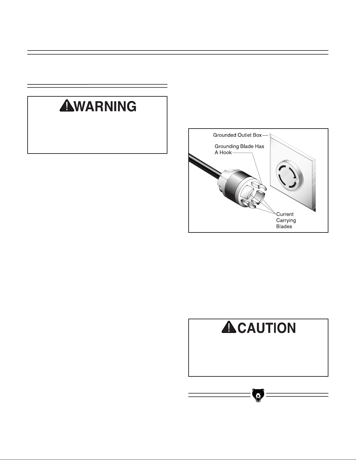
Figure 1a. Typical locking type L15-30 plug and
receptacle.
Serious personal injury could occur if you
connect your machine to the power source
before you have completed the set up
process. DO NOT connect the machine to
the power source until instructed to do so.
Wiring
The Model G0501 is prewired for 220V 3-phase
operation.
Amperage Draw
The Model G0501 has a 10 HP main motor and a
1 HP scoring motor that will draw the following
amps at 220V 3-phase:
Arbor Motor............................................25 Amps
Scoring Motor ..........................................3 Amps
Circuit Breaker Requirements
Install the machine on a dedicated circuit to
reduce the possibility of overloading the circuit
and tripping the circuit breaker. If the circuit
breaker trips and the circuit is of the correct load
capacity, have the circuit inspected by qualified
electrician. Never use a larger circuit breaker
than stated below, or you will increase the risk of
fire.
Circuit Breaker ............................30 Amp, 3 Pole
Minimum Cord Requirements
For 220V 3-phase operation, use the following
type of cord (a cord is not provided):
Cord................................................3 pole, 4 wire
Gauge ..............................................................10
Plug Type
The plug you install on your cord will depend
upon the type of service you currently have or
plan to install. We recommend using the following
plug and receptacle for your machine on a dedicated circuit only (see Figure 1a for an example):
Plug & Receptacle ..................................L15-30
220V 3-Phase
SECTION 3: CIRCUIT REQUIREMENTS
Page 12
-10- G0501 Sliding Table Saw
A fire may occur if your particular electrical
configuration does not comply with local
and state codes. The best way to ensure
compliance is to check with your local
municipality or a licensed electrician.
Your Shop Circuit Capacity
Always check to see if the wires in your circuit are
capable of handling the amperage draw from
your machine, as well as any other machines that
could be operating on the same circuit. If you are
unsure, consult a qualified electrician.
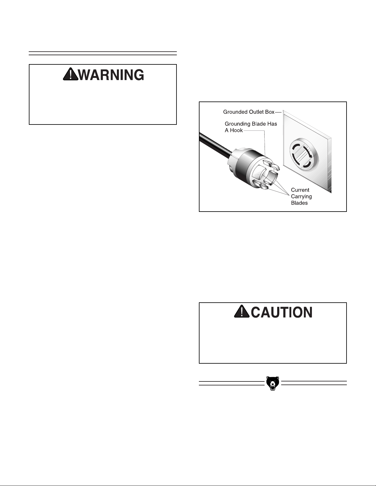
Figure 1b. Typical locking type L15-20 plug and
receptacle.
Serious personal injury could occur if you
connect your machine to the power source
before you have completed the setup
process. DO NOT connect the machine to
the power source until instructed to do so.
Wiring
The Model G0501 is prewired for 220V 3-phase
operation. If 440 voltage is required, rewire the
machine per the instructions on page 12 and follow the circuit requirements on this page.
Amperage Draw
The Model G0501 has a 10 HP main motor and a
1 HP scoring motor that will draw the following
amps at 440V 3-phase :
Arbor Motor ........................................12.5 Amps
Scoring Motor ......................................1.5 Amps
Circuit Breaker Requirements
Install the machine on a dedicated circuit to
reduce the possibility of overloading the circuit
and tripping the circuit breaker. If the circuit
breaker trips and the circuit is of the correct load
capacity, have the circuit inspected by qualified
electrician. Never use a larger circuit breaker
than stated below, or you will increase the risk of
fire.
Circuit Breaker ............................20 Amp, 3 Pole
Minimum Cord Requirements
For 440V 3-phase operation, use the following
type of cord (a cord is not included):
Cord................................................3 pole, 4 wire
Gauge ..............................................................12
Plug Type
The plug you install on your cord will depend
upon the type of service you currently have or
plan to install. We recommend using the following
plug and receptacle for your machine on a dedicated circuit only (see Figure 1b for an example):
Plug & Receptacle ..................................L15-20
440V 3-Phase
Page 13

G0501 Sliding Table Saw -11-
In the event of an electrical malfunction or breakdown, grounding provides a path of least resistance for electric current to reduce the risk of
electric shock. This machine must be equipped
with an electric cord that has an equipment
grounding conductor. This conductor must be
grounded in accordance with all local codes and
ordinances.
Improper connections of the electrical-grounding
conductor can result in the risk of electric shock.
Check with a qualified electrician or one of our
service personnel if the grounding instructions
are not completely understood, or if you are in
doubt as to whether the machine is properly
grounded.
Electrocution or fire could
result if this machine is
not grounded correctly.
Make sure all electrical circuits are grounded before
you connect them to the
machine. DO NOT use the
Model G0501 if it is not
grounded.
Because of the high amperage draw from this
machine, we do not recommend the use of extension cords. Instead, position your equipment near
installed wiring to eliminate the need for extension cords.
Extension CordsGrounding
Page 14

-12- G0501 Sliding Table Saw
The Model G0501 can be rewired for 440V operation. This rewiring job consists of disconnecting
the saw from the power source, changing the
connections on the voltage transformer, changing
the overload relays for the cutting motor and
scoring motor, and rewiring the cutting motor and
scoring motor.
The necessary overload relays for this procedure
can be purchased in the Model G0501 440V
Conversion Kit by calling our customer service
number at (800) 523-4777.
This procedure takes moderate electrical skill and
the rewiring job must be inspected by a licensed
electrician before the saw is connected to the
power source. Also, the motors can be accessed
easier for rewiring if the blade is moved to 0˚ (90˚
to table) before beginning.
To rewire the Model G0501 for 440V operation:
1. Disconnect the saw from the power source!
2. Open the electrical panel and locate the volt-
age transformer shown in Figure 2.
Rewiring to 440V
Figure 2. Inside view of the control panel.
Figure 3. Wire removed at 220V location and
connected to 440V location.
3. At the voltage transformer, remove the wire
that leads to the “220” terminal and connect
that wire to the “440” terminal (see Figure 3).
4. Remove the main motor overload relay (RH18/26 21-31A) and replace with the 440V
overload relay (RH-18/15 12-18A) that was
included with the Grizzly 440V conversion
kit. Set the overload relay dial to 13A.
5. Remove the scoring motor overload relay
(RH10E/3C 2.4-3.6A) and replace with the
440V overload relay (RH10E/1.7C 1.3-2A)
from the conversion kit. Set the overload
relay dial to 1.7A.
6. Open the motor cabinet door and remove the
motor wiring caps from the main motor and
the scoring motor.
7. Rewire the motors as shown on the diagrams
that are placed on the inside of the motor
wiring caps. Note—The diagram labeled
“Higher” is the correct wiring for 440V.
Voltage
Transformer
Scoring
Motor Relay
Main Motor
Relay
0 220 340 440 480
Voltage Transformer
Page 15

G0501 Sliding Table Saw -13-
1. Flip Stops—Used for quick measurements
for crosscutting.
2. Crosscut Fence—Used during crosscutting
operations. Features a scale and multiple
flip-style stopblocks for precise, repeatable
crosscutting operations.
3. Crosscut Table—Provides a wide, stable
platform for supporting full-size panels during
crosscutting operations.
4. Miter Fence—Allows precise miter cuts
between 30˚ and 135˚.
5. Control Panel & Digital Display—Features
a combination of digital and push-button controls for operating the many features of the
saw.
6. Sliding Table—Conveniently glides the
workpiece through the blade with effortless
precision and ease.
7. Rip Fence—Fully adjustable with microadjustments. Fence face can be positioned
for standard cutting operations, or in the
lower position for blade guard clearance during narrow ripping operations.
8. Riving Knife—Maintains kerf opening during
cutting operations. This function is crucial to
preventing kickback caused by the kerf closing behind the blade.
Figure 4. Main view of machine features and controls.
3
5
6
4
7
8
2
1
Main Features
SECTION 4: FEATURES & CONTROLS
Page 16

-14- G0501 Sliding Table Saw
9. Blade Guard—Fully-adjustable blade guard
allows high visibility of the cutting operation
while maintaining maximum protection
around the saw blade.
10. Upper Dust Collection Port—2" port opening allows effective dust extraction from
above the cutting operation.
11. Main Dust Collection Port—5" port allows
efficient high-volume dust extraction from
below the cutting operation.
13. Main Blade—Performs the cutting operations.
14. Scoring Blade—Small cutting blade that
rotates opposite the main saw blade. The
blade scores the workpiece before the actual cutting operation is performed; thus, preventing tear-out in laminate materials. The
scoring blade is adjustable forward and
backward, up and down, and in thickness of
kerf.
9
10
11
12
13
14
12. Rip Fence Scale—Allows precise measurement of rip cutting operations. Features a
dual calibration block for effortless scale
reading regardless of whether the fence is in
the high or low position.
Figure 5. Blade guard and dust ports.
Figure 7. Blades.
Figure 6. Rip fence scale.
Page 17

G0501 Sliding Table Saw -15-
Control Panel
A. EMERGENCY STOP Button—Disconnects
power to all motors in the motor cabinet.
B. MAIN BLADE OFF Button—Stops the main
saw blade.
C. SCORING BLADE OFF Button—Stops the
scoring blade.
D. MAIN BLADE DOWN Key—Lowers the
height of the main saw blade.
E. SCORING BLADE RIGHT Key—Moves the
scoring blade right for alignment purposes.
F. SCORING BLADE DOWN Key—Lowers the
height of the scoring blade.
G. C Key—Clears typed entries in the display.
H. Keypad—Keys for inputting the desired
angle of the saw blade.
I. Stop Key—Stops the trunnion movement.
J. Start key—Starts trunnion movement after
an angle has been entered.
K. “+” Key—Manually increases the angle of
the saw blades in increments of 0.1˚.
A
N
M
L
K
I
J
B
H
G
C
D
E
F
O
P
Q
T
R
S
L. “-” Key—Manually decreases the angle of
the saw blades in increments of 0.1˚.
M. Set Key—Used to set blade angles entered
into the keypad. Also, used for calibration.
N. Digital Display—Displays the current angle
of the saw blades.
O. SCORING BLADE UP Key—Raises the
height of the scoring blade.
P. ARBOR RPM Display—Displays the current
RPM of the saw blades.
Q. SCORING BLADE LEFT Key—Moves the
scoring blade left for alignment purposes.
R. MAIN BLADE UP Key—Raises the height of
the main saw blade.
S. SCORING BLADE ON Button—Starts the
scoring blade. Note—The main saw blade
must be ON for the scoring blade to start.
T. MAIN BLADE ON Button—Starts the main
saw blade.
Figure 8. Control panel close-up.
Page 18

-16- G0501 Sliding Table Saw
A. Fence Assembly Lock Down Lever—
Secures the fence assembly into position
along the fence rail.
B. Micro-Adjust Knob—Precisely adjusts the
fence.
C. Forward/Backward Slide Lock Handle—
Secures the aluminum fence piece on its forward/backward slide track.
D. Micro-Adjust Lock Knob—Secures the
fence after it has been adjusted with the
micro-adjustment knob.
Figure 9. Rip fence controls.
Blade Guard
Controls
A
B
D
C
Figure 10. Blade guard controls.
A
B
C
A. Height Adjustment Locking Lever—
Secures the blade guard in the desired vertical position by clamping the dovetail slide.
B. Leveling Adjustment Locking Lever—
Allows the blade guard to be adjusted horizontally to level the blade guard with the
table or workpiece.
C. Mechanical Height Control Lever— Raises
and lowers the blade guard to adjust the
height when the height adjustment locking
lever is released.
Rip Fence Controls
Page 19

G0501 Sliding Table Saw -17-
Main Crate:
• Saw Base Unit
• Blade Guard
• Blade Guard Lower Support Arm
• Blade Guard Upper Support Arm
• Blade Guard Swing Arm
• Push Stick
• Large Extension Table
• Large Extension Table Braces (2)
• Small Extension Table
• Small Extension Table Braces (2)
• Crosscut Table
• Riving Knife
• Rip Fence Rail
• Rip Fence Clamp
• Tool Box
—Feet (4)
—Foot Studs (4)
—Combo Arbor Wrench 30, 36 MM
—Combo Wrench 22, 24 MM
—10 pc Hex Key Set
—6 pc Combo Wrench Set
—Arbor Locking Tool
Fence Crate:
• Sliding Table
• Crosscut Fence
• Extruded Aluminum Rip Fence
• Miter Fence
• Long Crosscut Table Brace
• Short Crosscut Table Brace
• Sliding Table End Handle
• Sliding Table End Cap
• Flip Stop w/Indicator on End
• Flip Stop w/Indicator in Middle
• Sliding Table Rail Handle
• Bar w/Scale
• Flat Head Screws (4) M6-1.0 x 30
The Model G0501 is shipped from the manufacturer in a carefully built crate. If you discover the
machine is damaged after you have signed for
delivery, please immediately call Customer
Service at (570) 546-9663 for advice.
Save the containers and all packing materials for
possible inspection by the carrier or its agent.
Otherwise, filing a freight claim can be difficult.
When you are completely satisfied with the condition of your shipment, you should inventory the
equipment from the shipping crate.
The purpose of this section is to guide you
through the required steps to get your machine
out of its crate and into operating condition.
Wear safety glasses during the entire set up
process!
This machine presents
serious injury hazards
to untrained users. Read
through this entire manual to become familiar
with the controls and
operations before starting the machine!
Piece Inventory
Unpacking
About this Section
SECTION 5: SET UP
Page 20

-18- G0501 Sliding Table Saw
Figure 11. Saw unit.
Figure 12. Blade guard assembly.
Figure 13. Extension tables and braces.
Figure 14. Rip fence components and
push stick.
In the event that any non-proprietary parts are
missing (e.g. nuts or washers), we would be glad
to replace them, or for the sake of expediency,
replacements can be obtained at your local hardware store.
Page 21

G0501 Sliding Table Saw -19-
Figure 17. Sliding table.
Figure 15. Crosscut fence components.
Figure 16. Toolbox inventory.
Page 22

-20- G0501 Sliding Table Saw
Hardware Recognition Chart
Page 23
G0501 Sliding Table Saw -21-
Figure 18. Working clearances.
Floor Load
The Model G0501 weighs 2314 lbs. and has a
base footprint of 64
1
⁄2" W x 39" D. Most commercial floors are suitable for your machine. Some
residential floors may require additional reinforcement to support both the machine and operator.
Working Clearances
Consider existing and anticipated needs, size of
material to be processed through each machine,
and space for auxiliary stands, work tables or
other machinery when establishing a location for
your saw. See Figure 18 for the maximum working clearances of the Model G0501.
Unsupervised children and
visitors inside your shop
could cause serious personal injury to themselves. Lock
all entrances to the shop
when you are away and DO
NOT allow unsupervised
children or visitors in your
shop at any time!
The unpainted surfaces are coated with a waxy
oil to protect them from corrosion during shipment. Remove this protective coating with a solvent cleaner or citrus-based degreaser such as
Grizzly’s G7895 Degreaser. To clean thoroughly,
some parts may need to be removed. For opti-
mum performance from your machine, make
sure you clean all moving parts or sliding
contact surfaces that are coated. Avoid chlo-
rine-based solvents as they may damage painted
surfaces should they come in contact. Always follow the manufacturer’s instructions when using
any type of cleaning product.
Gasoline and petroleum
products have low flash
points and could cause
an explosion or fire if
used to clean
machinery. DO NOT use
gasoline or petroleum
products to clean the
machinery.
Smoking near solvents
could ignite an explosion
or fire and cause serious
injury. DO NOT smoke
while using solvents.
Many of the solvents
commonly used to clean
machinery can be toxic
when inhaled or ingested. Lack of ventilation
while using these solvents could cause serious personal health risks
or fire. Take precautions
from this hazard by only
using cleaning solvents
in a well ventilated area.
Site ConsiderationsClean Up
193" (Fully Extended)
243.5"
Page 24

-22- G0501 Sliding Table Saw
Moving & Placing
Saw Base Unit
To remove the saw base unit from the crate
pallet:
1. Cut off and remove all plastic straps from the
crate.
2. Position the forklift forks together and directly above the saw.
3. Place two lifting straps over the forks and
attach the ends to the lifting bolts as shown
in Figure 19.
Figure 20. Foot studs placed in base feet.
Figure 19. Lifting the saw base unit.
4. Lift the saw base unit and move it to your
predetermined location.
5. Before lowering the saw into position, place
safety blocks under the frame and thread the
four foot studs into the frame at least half of
their length.
6. Remove the safety blocks and lower the saw
onto the feet as shown in Figure 20 and
remove the forklift straps.
The Model G0501 is a
heavy machine that
weighs approximately
2300 lbs. Serious personal injury may occur if
safe moving methods
are not followed. To be
safe, you will need assistance and power equipment when moving the
shipping crate and
removing the machine
from the crate.
7. Place a level on the saw table and adjust foot
studs so the the saw table is level from left to
right and from front to back.
8. Lock the foot studs in position by tightening
their jam nuts against the machine body.
Page 25

G0501 Sliding Table Saw -23-
Table Installation
The sliding table for the
Model G0501 weighs
over 350 lbs. Use at least
four strong people to lift
it in position. Improper
lifting techniques or
inadequate lifting assistance could result in
serious crushing or
strain injuries.
Installing the sliding table is a difficult procedure
because the sliding table is very heavy and
because the attachment blocks inside the table
need to be aligned with the attachment holes on
the bottom of the table.
Figure 21. Control panel shipping brace.
Figure 23. Control panel correctly set up.
Figure 22. Control panel face and side cap
screws.
To set up the control panel:
1. Using a 6mm hex wrench, remove the red
control panel shipping brace shown in
Figure 21.
2. Remove the three cap screws on the face of
the control panel to open the cover.
3. Remove the three cap screws and nuts from
the inside left edge of the control panel
(Figure 22).
4. Swing the control panel against the frame of
the saw and secure it in place with the three
caps screws that you removed from the
inside of the control panel in step 3.
5. Close the control panel face and secure it
with the three cap screws that originally kept
it closed, so the control panel is set up similar to the photo in Figure 23.
Setting Up Control
Panel
Page 26

-24- G0501 Sliding Table Saw
Figure 25. Three large caps screws to be
removed from saw base unit.
Figure 24. Blade tilt shipping brace.
Figure 26. Parallel adjustment bolts.
To install the sliding table:
1. Remove the red shipping brace, shown in
Figure 24, from the blade tilt mechanism.
3. Back out the parallel adjustment bolts shown
in Figure 26, but do not completely remove
them or the jam nuts that are installed on
them.
2. Using a 12mm hex wrench, remove the three
large cap screws (Figure 25) from the saw
base unit.
4. While the sliding table is still in its crate, pencil a light mark on the front of the table that
references the middle mounting hole. Note—
This step will save time when positioning the
sliding table on the base unit.
5. Now, locate the middle attachment hole on
the base unit (where you removed the large
cap screws in step 2) and pencil a light alignment mark on the front of the machine base
unit.
6. Use at least four strong people to lift the sliding table onto the base unit. The edge of the
sliding table should be up against the edge of
the base unit table and the penciled reference marks should be aligned with each
other.
7. Have two of your assistants hold the sliding
table in position so that it does not fall while
you are securing it to the base unit.
Page 27

G0501 Sliding Table Saw -25-
Figure 27. Sliding table shipping brace.
Figure 29. Sliding table handles.
Figure 28. Access panel removed (one side
shown).
Figure 30. Sliding table end cap attachment
screws.
8. Remove the shipping brace, shown in Figure
27, from the end of the sliding table.
9. From the end of the sliding table, look inside
the sliding table and locate the three attachment blocks. These need to be positioned
over the attachment holes. The scale bar is
an excellent tool for inserting into the table
and positioning the blocks.
10. Starting at the middle hole, reach through the
dust port opening and stick your finger in the
attachment hole. Have your third assistant
use the scale bar to push or pull the middle
attachment block so that you can align it with
your finger.
11. Once aligned, thread one of the large cap
screws from the base into the attachment
block, but DO NOT completely tighten with
the hex wrench until instructed later in this
manual.
12. Remove the two access panels from the
back of the base unit (Figure 28) so that you
can access both of the remaining attachment
holes.
13. Utilizing the same procedures from steps 10
& 11, thread the remaining two cap screws
from the base into the sliding table attachment blocks.
14. Install the sliding table handles and end cap
(shown in Figure 29 & 30) with two flat head
screws per each, securing from the top of the
table.
Page 28
-26- G0501 Sliding Table Saw
Installing Blade
Guard
The blade guard assembly consists of four
pieces: Lower and upper support arms, a pivoting
swing arm and a clear plastic blade guard shield.
To install the blade guard:
1. Remove the six bolts from the side of the
motor cabinet.
2. Position the lower support arm over the holes
on the side of the motor cabinet and secure
it with the bolts and lock washers removed in
step 1, so the assembly looks similar to
Figure 31.
Figure 31. Lower support arm installed.
Figure 33. Pivot bolt.
Figure 32. Vertical support installed.
3. Unthread the eight bolts from the upper sup-
port arm.
4. Position the upper support arm over the
holes in the lower support arm and secure it
with the bolts removed in step 3 (Figure 32).
6. Position the pivoting swing arm over the saw
table (Figure 34) and secure it with four
M10-1.5 x 25 bolts, lock washers and flat
washers. Note—Get assistance holding the
swing arm in place while securing it to the
support.
Pivot Bolt
Pivoting Swing
Arm
Steel Mounting
Brace
5. Loosen the pivot bolt (Figure 33) at the end
of the swing arm to position the steel mounting brace over the end of the upper support
arm.
Lower Support
Arm
Upper
Support Arm
Page 29
G0501 Sliding Table Saw -27-
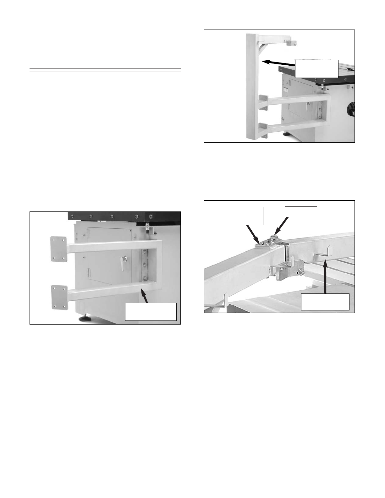
Installing Extension
Tables
To install the extension tables:
1. Assemble the braces to the underside of the
small and large extension table, as shown in
Figures 36 & 37. Note—Do not fully tighten
the braces to the tables. They will need to be
adjusted during installation.
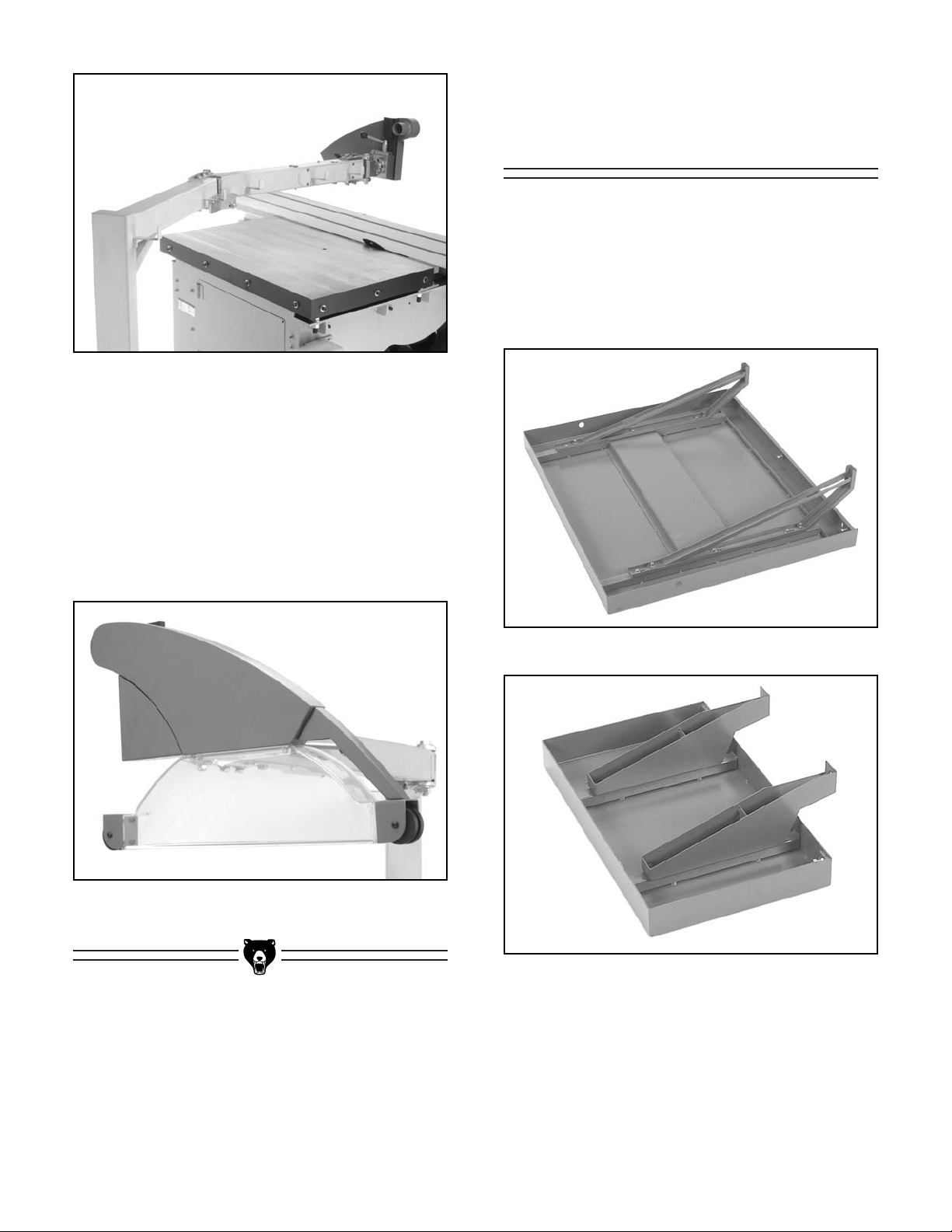
Figure 34. Pivoting swing arm installed on
supports.
Figure 35. Clear blade shield installed.
Figure 36. Large extension table and braces.
Figure 37. Small extension table and braces.
7. Remove the four cap screws under the blade
guard and one cap screw at the front.
8. Position the clear blade shield guide holes
under the blade guard arm (Figure 35) and
secure it with the cap screws removed in
step 7. Note—Overtightening cap screws
may crack the blade guard.
Page 30

-28- G0501 Sliding Table Saw
Figure 38. Hardware location for small table.
Figure 39. Small extension table installed.
Figure 40. Checking with a straight edge.
4. Use the adjustment screws (Figure 39)
under the extension table to level the top surface with the saw table.
5. When the surfaces are level, slide the table
supports against the machine frame and
secure them with the cap screws.
7. Position the adjustment screws between the
table support braces and extension table to
finely tune the table so it is level.
8. To install the large extension table, move to
the back of the saw and remove the four cap
screws from cast iron table and the four cap
screws from the cabinet.
9. With the help of at least two assistants, install
and level the large extension table in the
same manner as the small extension table,
using the hardware removed in step 8.
Figure 41 shows the large extension table
installed correctly.
3. Position the small extension table over the
holes on the cast iron table and secure it with
the three cap screws that you removed in
step 2 (Figure 39). Note—Get assistance
positioning the table and holding it in place
while installing.
Cap Screws
Adjustment Screws
6. Check the surfaces of the table with a
straight edge a shown in Figure 40.
2. Remove the three cap screws, lock washers
and flat washers from the side of the table
(Figure 38, white arrows) and remove the
two cap screws from the motor cabinet
(Figure 38, black arrows).
Figure 41. Large extension table installed.
Page 31

G0501 Sliding Table Saw -29-
6. Slide one end of the aluminum fence piece
over the mounting track on the side of the
fence clamping assembly. Note—The alu-
minum fence piece should slide smoothly
back and forth. The handle on the top of the
clamping assembly rotates to lock the aluminum fence piece into position (Figure 44).
Figure 44. Installing aluminum fence to
clamping assembly in upward position.
Figure 43. Installed clamp assembly.
Figure 42. Fence rail installed.
Rip Fence
4. Secure the fence scale to the edge of the
cast iron/extension table edge with the four
M6-1.0 x 30 flathead cap screws from the
packing inventory.
5. Slide the rip fence clamping assembly onto
the end of the fence rail (Figure 43). Note—
The fence clamping assembly will not slide
onto the rail if the clamping lever is in the
locked position.
To install the rip fence:
1. Locate the fence rail and remove the last nut
and washer from each threaded mounting
post.
2. Position the three rail bolts in the location
holes along the cast iron table and large
extension table. Note—The center mounting
post is positioned closer to one end of the
rail. Align the mounting posts with the the
mounting holes accordingly.
3. Secure the rail by installing the washer and
nut that were removed in step 1 to the backside of the tables. Figure 42 shows the rail
installed.
Lock
Handle
Page 32

-30- G0501 Sliding Table Saw
Figure 45. Installed clamp assembly.
7. Check if the bottom edge of the aluminum
fence piece rests on the top surface of the
table. Note—The aluminum fence piece will
scratch the table surface if the ride height is
not adjusted correctly.
— If the bottom edge of the aluminum fence
piece does not rest on the table, then
fence is correctly adjusted. Proceed to the
next sub-section.
— If the bottom edge of the aluminum fence
piece does rest on the table, then contin-
ue on to the next step.
8. Loosen the cam bolt located on the end of
the fence clamp assembly (see Figure 45).
Crosscut Table
To assemble the crosscut table:
1. Swing the crosscut table brace away from
the table saw base. Note—A magnet holds
the support against the base. A strong pull is
necessary to free the support.
2. Position the brace perpendicular to the long
edge of the sliding table.
3. One end of the crosscut table has a clamping assembly designed to attach to the bar
on the sliding table. The two cap screws
(Figure 46) located under the clamp need to
be backed out far enough to allow the clamp
to slip over the bar on the sliding table.
9. Rotate the cam up or down to adjust the ride
height of the fence.
10. Retighten the cam bolt and check the ride
height. Re-adjust if necessary.
4. Lift the crosscut table and slip the clamp over
the bar on the sliding table and set the other
end of the crosscut table onto the shaft that
protrudes up from the brace (Figure 47).
Figure 46. Cap screws used to secure the
crosscut table clamping assembly.
Page 33

G0501 Sliding Table Saw -31-
Figure 47. Mounting the crosscut table over the
shaft on the brace.
Figure 48. Cross-support assemblies.
Figure 49. Cam lock rod (1 of 2).
5. Remove both end caps from the short cross-
support and remove one end cap from the
long cross-support as shown in Figure 48.
9. Using the handles on the crosscut fence,
slide the 2 cam lock rods into the crosscut
table (Figure 49). Note—Make sure the lock-
ing bolts on the crosscut fence are disengaged so the locating pins will easily fall into
the table extension.
6. Loosen the hold-down assemblies that
secure each of the cross-supports.
7. Slide the cross-supports into position and
secure them by tightening the hold-down
assemblies.
8. Place the crosscut fence on the crosscut
table so that the locating pins fit inside the
guide holes.
10. Install the flip stop units in the crosscut fence
by unlocking the extension piece and aligning the clamp bar on the bottom of the flip
stop unit to slide it into the fence. The correct
order of placement for the flip stop units is
shown in Figure 50.
Figure 50. Correct order of flip stop unit
placement.
Inside Flip Stop
Outside Flip Stop
Mounting
Shaft
Cam Lock Rod
Cross-support
Hold-Down
Assembly
Cross-support
Page 34

-32- G0501 Sliding Table Saw
Miter Fence
To install the miter fence:
1. Loosen the clamp plate with the ratchet han-
dle to prepare the miter fence for installation.
2. Align the fixed bolt in the slot closest to the
blade and align the clamp plate in the other
slot as shown in Figure 51.
Figure 51. Miter fence components aligned for
installation of miter fence.
Fixed Bolt
Clamp Plate
Figure 52. Miter fence set to 45˚ mark on the
miter gauge scale.
3. Thread the fixed bolt into the fixed block. The
miter fence should now slide up and down
the angle range freely.
4. Position the fence at the desired angle and
use the clamp plate ratcheting handle to lock
the fence in place. Figure 52 shows the miter
fence set to 45˚ on the miter fence scale.
Page 35

G0501 Sliding Table Saw -33-
Test Run
Now that the machine is connected to the power
source, it is important to perform a test run to
make sure all the controls are working properly.
Before starting the saw, make sure you
have performed the preceding assembly
and adjustment instructions, and you have
read through the rest of the manual and are
familiar with the various functions and safety issues associated with this machine.
Failure to follow this warning could result in
serious personal injury or even death!
To test run the saw:
1.
Put on safety glasses and make sure any
bystanders are out of the way and also wearing safety glasses.
2. Turn the switch on the side of the control
panel to ON. This is the main power switch.
3. At the front of the control panel, rotate the
red EMERGENCY STOP button until it
springs up. The control panel is now live and
any buttons you push will react accordingly.
4. Turn to page 14 and experiment with all of
the controls until you are familiar and comfortable with them.
— If the blade moves in the wrong direction,
then disconnect the power and switch the
power wires at the circuit breaker in the
electrical box.
— If any problems occur, press the EMG
STOP button. Investigate and correct the
problem before operating the machine
further. If you need help, refer to the troubleshooting section in the back of this
manual or contact our service department
at (570) 546-9663.
The remaining adjustments in this section require
you to connect the power cord to the saw and
install a plug on the power cord. Before begin-
ning, read Section 3: Circuit Requirements to
make sure your setup meets the requirements of
the machine.
To connect the saw to the power source:
1. Read through Section 3: Circuit
Requirements to double-check that your
setup follows the safety and circuit requirements, and that the power cord you have
chosen meets the minimum requirements for
this machine.
2. Open the control panel box.
3. Feed the power cord through the strain relief
on the side of the control panel, and connect
the cord wires to the main terminal (Figure
53).
4. Close the control panel door.
Figure 53. Main terminal located inside saw
control panel.
5. Connect the power cord to an L15-30 Plug.
Note—You must have an L15-30 receptacle
to use with the L15-30 plug.
Power Cord
Page 36

-34- G0501 Sliding Table Saw
Figure 55. Sliding table parallel adjustment bolt
(other side not shown).
9. Repeat steps 5–6 until the gap between your
mark on the blade and the edge of the sliding
table is even at both ends.
10. Tighten the jam nuts on the parallel adjustment bolts to secure them in place
11. Now tighten the three large cap screws
(Page 23, Figure 25) that secure the sliding
table to the base.
Sliding Table
Parallel Adjustment
Now is the point in the assembly process to make
the sliding table parallel with the main saw blade
and tighten the three large cap screws that were
used to secure the sliding table to the saw base.
Besides the tools included with the saw, this procedure requires you to have a precision ruler, a
felt tip pen, and the assistance of another person.
To adjust the sliding table parallel with the
main blade:
1. Set the blade to 0˚ on the control panel (90˚
with the cast iron table).
2. Raise the main blade up as far as it will go.
3. Disconnect the saw from the power source!
4. Mark the center of the blade with a felt tip
pen. This will allow you to take your measurements from the exact same place on the
blade.
5. Move the sliding table all the way to one end,
and using a precision ruler, measure the gap
between the edge of the table and your mark
on the blade as shown in Figure 54.
Figure 54. Measuring gap between sliding table
edge and center of blade with a precision ruler.
6. Move the other end of the sliding table in
front of the blade and measure the gap.
— If the gap is the same on both sides, then
the sliding table is already parallel with
the main blade. Skip to step 10.
— If the gap on one side is different than the
other, then continue with step 7.
7. Move the end of the sliding table that needs
to be adjusted in front of the blade.
8. Using the ruler, watch the gap measurement
and have your assistant slowly make the
adjustments at the parallel adjustment bolts
(Figure 55) until the gap size is equal to the
other side.
Page 37

G0501 Sliding Table Saw -35-
Fence Scale
Alignment
Before operation, the 0" mark on the rip fence
scale must be aligned with the right side of the
blade to ensure that the rip fence measurements
will be accurate.
To align the fence scale with the blade:
1. Set the blade to 0˚ on the control panel (90˚
with the cast iron table).
2. Raise the main blade up as far as it will go.
3. Disconnect the saw from the power source!
4. Remove the stop bolt shown in Figure 56.
Figure 56. Rip fence stop bolts
Figure 58. Rip fence scale lock knob.
5. Move the rip fence all the way against the
blade as shown in Figure 57.
7. Move the fence away from the blade and re-
install the stop bolt that was removed in step
4.
Figure 57. Rip fence aligned with blade.
6. Loosen the scale lock knob (Figure 58),
adjust the scale 0" mark even with the fence,
and tighten the scale knob to keep the scale
in place.
Page 38

-36- G0501 Sliding Table Saw
NOTICE
Remember maximum working clearances
when installing dust hoses.
Dust Collection
The Model G0501 is equipped with two dust ports
that should be properly connected to a dust collection system before operation.
To connect the dust ports to a dust collection
system:
1. Secure a 5" dust hose to the dust port locat-
ed under the saw table (Figure 59).
Figure 59. 5" dust port location.
Figure 60. 2" dust port location.
2. Run the 5" hose to your dust collection sys-
tem.
4. Run the 2" hose along the braces on the
back of the blade guard swing arm to your
dust collection system. Make sure to leave
extra slack in the dust hose near swing arm
pivot points.
3. Connect a 2" dust hose to the port located
above the blade guard shown in Figure 60.
5. Run a ground wire along the dust hose and
attach the wire to the machine to protect
against static electricity.
Page 39

G0501 Sliding Table Saw -37-
NOTICE
The following section was designed to give
instructions on the basic operations of this
machine. However, it is in no way comprehensive of all of the machine’s applications.
WE STRONGLY RECOMMEND that you read
books, trade magazines, or get formal training to maximize the potential of your
machine.
Damage to your eyes, lungs, and ears could
result from using this machine without proper protective gear. Always wear safety glasses, a dust mask, and hearing protection
when operating this machine.
Loose hair and clothing
could get caught in
machinery and cause
serious personal injury.
Keep loose clothing and
long hair away from moving machinery.
Operation Tips
Your safety is important. The tips below are
intended to supplement Section 2: Safety. But
remember, no safety list can be comprehensive
of every situation. The operator is ultimately
responsible for their own safety, as well as the
safety of bystanders. Every cutting operation is
uniquely different and may require safety equipment or safety procedures not mentioned in this
manual.
Please follow these tips EVERY time you use
your saw:
• Stand to the left of the blade line-of-cut when
performing a cutting operation.
• Turn off the saw and allow the blade to come
to a complete stop before removing the cutoff piece.
• Make sure that the riving knife is always
aligned with the main blade before cutting!
• Always position the blade guard to the correct height above the workpiece.
• Carefully plan each cutting operation to avoid
injuries.
• When you release the sliding table lock,
make sure that the knob is positioned so that
it will not lock the table during a cut.
SECTION 6: OPERATIONS
Page 40

-38- G0501 Sliding Table Saw
The blades for the Model G0501 can operate at
3000, 4000, 5000, and 6000 RPM. This speed
can be easily changed by moving the V-belt position on the main motor pulley and arbor pulley.
To change the blade speed:
1. Disconnect the saw from the power
source!
2. Remove the cap screws on the top and bot-
tom right corners, then open the motor cabinet door.
3. Move the belt tension handle (Figure 61)
down to loosen the V-belt.
Changing Blade
Speeds
Figure 61. Belt tension release handle.
The blade can be tilted anywhere from 0˚ to 45˚.
To change the blade tilt:
1. Turn the main power switch ON.
2. Rotate the red EMERGENCY STOP button
until it springs up.
3. Press SET on the keypad.
4. Type in your desired blade tilt. (For example:
If you want the blade to tilt to 30˚, type 3, 0.)
5. Press START on the keypad. The blade
should now move to your desired tilt.
Changing Blade Tilt
Page 41

G0501 Sliding Table Saw -39-
5. Turn the pulley speed switch (Figure 63) so
that the opening in the fins line up with the
belt position. This switch registers the speed
with the control panel.
Figure 62. Belt speed diagram.
Figure 64. Fence against blade as a guide for
aligning the scoring blade.
Figure 63. Pulley speed switch.
The scoring blade must be aligned with the main
blade to ensure satisfactory cutting results.
Before attempting to align the scoring blade with
the main blade, the kerf thickness must match
that of the main blade.
To align the scoring blade set:
1. Move the blade tilt to 0˚ on the control panel
(blade 90˚ to table), and raise the main blade
and scoring blade set up as far as they will
go.
2. Remove the stop bolt from the rip fence, and
move the rip fence against the main blade (or
scoring blade) as shown in Figure 64.
Aligning Scoring
Blade Set
4. Position the V-belt in one of the pulley loca-
tions illustrated in Figure 62, depending on
your desired blade speed.
Pulley Speed
Switch
6. Move the belt tension handle up to tighten
the V-belt.
7. Close and secure the motor cabinet door.
3. Use the control panel to move the scoring
blade so that the rip fence can touch both the
scoring blade and the main blade when positioned as shown in Figure 64.
4. Lower the scoring blade to the correct height
and perform a test cut, then make any final
adjustments.
5000
3000
4000
6000
Page 42

-40- G0501 Sliding Table Saw
The Model G0501 has the capability of rip cutting
full size panels (Figure 65). The sliding table
removes the burden of sliding a large and heavy
panel over a stationary table surface.
This saw also has the capability of rip cutting
smaller boards, using the machine as a traditional table saw (Figure 66). Smaller, lighter boards
are easier to slide across the stationary cast iron
table surface to the right of the saw blade.
Rip Cutting
Figure 65. Rip cutting setup with the sliding
table.
Figure 66. Rip cutting using the traditional
table saw technique.
Determine which cutting operation will be best
suited for the workpiece to be ripped.
— To use the sliding table, read the instruc-
tions titled “Rip cutting with the sliding
table.”
— To use the machine as a traditional table
saw, skip ahead to “Rip cutting using the
traditional table saw technique.”
Rip cutting with the sliding table:
1. Mount the crosscut table to the sliding table.
2. Slide and secure the crosscut table to the
end of the sliding table opposite the sliding
table handle.
3. Install the crosscut fence in the guide pin
holes shown in Figure 67 and lock it in place
with the cam locks. Note—First, drop the
crosscut fence into the outside edge guide
pin hole, then drop the other end of the
crosscut fence into the guide pine hole closest to the sliding table.
Figure 67. Guide pin holes used when mounting
the crosscut fence for rip cutting operations.
4. Set either flip stop to the desired width-of-cut.
Page 43

G0501 Sliding Table Saw -41-
5. Position the blade guard to the correct height
for your workpiece.
6. Load the workpiece onto the table saw. The
set up should look similar to Figure 65.
7. Once all the necessary safety precautions
have been taken, perform the cutting operation.
Rip cutting using the traditional table saw
technique:
1. Slide the crosscut table out of the way.
2. Lock the sliding table into a stationary posi-
tion.
3. Position the rip fence to the desired width-ofcut.
4. Slide the leading end of the rip fence so it is
even with the center of the main saw blade
as shown in Figure 68. Note—This tech-
nique allows the finished cut-off piece to “fall”
away from the blade when the cutting operation is complete; therefore, reducing the possibility of kickback and preventing the trailing
corner of the workpiece from being nicked by
the back edge of the blade.
Figure 68. Rip fence set even with center of
blade.
5. Position the blade guard to the correct height
for your workpiece.
6. Once all the necessary safety precautions
have been taken, load the workpiece onto
the table saw and perform the cutting operation.
Page 44

-42- G0501 Sliding Table Saw
Figure 71. Crosscutting workpieces
using the rip fence as a cut-off gauge.
Lastly, this machine has the capability of crosscutting workpieces while using the rip fence as a
cut-off gauge (Figure 71).
Determine which cutting operation will be best
suited for the workpiece to be crosscut.
— If you will be crosscutting full size panels,
then skip ahead to “Crosscutting full size
panels.”
— If you will be crosscutting smaller panels,
then skip ahead to “Crosscutting smaller
panels.”
— If you will be crosscutting workpieces
using the rip fence as a cut-off gauge,
then skip ahead to “Crosscutting using
the rip fence as a cut-off gauge.”
Figure 70. Crosscutting smaller panels.
Figure 69. Crosscutting full size panel.
With the crosscut fence mounted in the forward
position (Figure 69), the Model G0501 has the
capability of crosscutting full size panels.
With the crosscut fence mounted in the rear position (Figure 70), this machine also has the capability of crosscutting smaller panels.
Crosscutting
Forward Mounted
Crosscut Fence
Rear Mounted
Crosscut Fence
Page 45

G0501 Sliding Table Saw -43-
Crosscutting full size panels:
1. Mount the crosscut table to the sliding table.
2. Install the crosscut fence in the forward guide
pin holes shown in Figure 72 and lock it in
place. Note—First, drop the crosscut fence
into the outside edge guide pin hole, then
drop the other end of the crosscut fence into
the guide pine hole closest to the sliding
table.
Figure 72. Guide pin holes used when mounting
the crosscut fence for full size
panel crosscutting.
3. Set either flip stop to the desired width-of-cut.
Note—If the workpiece extends to the left of
the saw blade more than 66", then the crosscut fence slide needs to be extended.
4. Position the blade guard to the correct height
for your workpiece.
6. Load the workpiece onto the table saw. The
set up should look similar to Figure 69.
7. Once all the necessary safety precautions
have been taken, perform the cutting operation.
Forward Guide
Pin Holes
Rear Guide
Pin Holes
Crosscutting smaller panels:
1. Mount the crosscut table to the sliding table.
2. Install the crosscut fence in the rear guide
pin holes shown in Figure 72 and lock it in
place. Note—First, drop the crosscut fence
into the outside edge guide pin hole, then
drop the other end into the guide pin hole
closest to the sliding table.
3. Set either flip stop to the desired width-of-cut.
Note—If the workpiece extends to the left of
the saw blade more than 66", then the crosscut fence slide needs to be extended.
4. Position the blade guard to the correct height
for your workpiece.
5. Load the workpiece onto the table saw. The
set up should look similar to Figure 69.
6. Once all the necessary safety precautions
have been taken, perform the cutting operation.
Crosscutting using the rip fence as a cut-off
gauge:
1. Mount the crosscut table to the sliding table.
2. Install the crosscut fence in the rear guide
pin holes shown in Figure 72 and lock it in
place. Note—First, drop the crosscut fence
into the outside edge guide pin hole, then
drop the other end into the guide pin hole
closest to the sliding table.
3. Position the rip fence to the desired width-ofcut.
4. Load the workpiece onto the table saw. The
set up should look similar to Figure 71.
5. Slide the leading end of the rip fence behind
the back edge of the workpiece as shown in
Figure 73. Note—When using the crosscut
fence, the workpiece should never be making contact with the saw blade and the rip
fence at the same time.
Page 46

-44- G0501 Sliding Table Saw
Figure 73. Correct rip fence position when per-
forming crosscutting operations.
6. Position the blade guard to the correct height
for your workpiece.
7. Once all the necessary safety precautions
have been taken, perform the cutting operation.
Figure 74. Example of miter cutting operation
for a cut length less than 45".
Figure 75. Example of miter cutting operation
for a cut length over 45".
The miter fence allows miter cuts from 30˚
through 135˚ on boards ranging in length from
9
1
⁄2" through 861⁄2". The table mounted miter scale
has a resolution of
1
⁄2˚. Either end of the flip stop
slide can be slid into the end of the miter fence to
accommodate cut off lengths both over and under
45" as shown in Figure 74 & 75.
Miter Cutting
Page 47

G0501 Sliding Table Saw -45-
Figure 77. Flip stop slide lock knobs.
3. Loosen the lock knobs that secure the flip
stop slide into position in the miter fence
(Figure 77).
To perform a miter cut:
1. Mount the miter fence onto the sliding table.
2. Position the fence at the desired angle and
use the clamp plate ratcheting handle to lock
the fence in place. Figure 76 shows the miter
fence set to 45˚ on the miter fence scale.
Lock Knobs
Flip Stop
Miter Fence
Figure 76. Miter fence set to 45˚ mark on the
miter fence scale.
Clamp Plate
Ratcheting Handle
Figure 78. Miter fence slide installation for cut
lengths between 9
1
⁄2" and 45".
4. Position the flip stop according to the length
of the workpiece you want to cut off to the left
of the blade.
— If the desired cut-off length to the left of
the blade is between 9
1
⁄2" and 45", then
the flip stop-end of the slide bar needs to
be slid into the main miter fence body first
(Figure 78).
— If the desired cut-off length to the left of
the blade is between 45" and 86
1
⁄2, then
the slide bar end opposite the flip stop
needs to be slid into the main miter fence
body first (Figure 79).
Figure 79. Miter fence slide installation for cut
lengths between 45" and 86
1
⁄2.
Page 48

-46- G0501 Sliding Table Saw
5. Position the blade guard to the correct height
for your workpiece.
6. Load the workpiece onto the table saw. The
set up should look similar to Figure 74 or 75.
7. Once all the necessary safety precautions
have been taken, perform the cutting operation.
The Model G0501 will perform best when high
quality, sharp blades are used. Therefore, whenever the main blade starts to get dull, we recommend that you have it resharpened or replace it
with a new blade.
Also, the Model G0501 is designed to accommodate either a 12" or a 14" main blade. But any
time you change blade sizes, the appropriate
sized riving knife must also be changed to match
the size of blade you install.
To change main blade:
1. Move the blade tilt to 0˚ on the control panel
(blade 90˚ to table).
2. Disconnect the saw from the power
source!
3. Move the sliding table all the way to the left
and push the release knob to expose the
internal blade guard that covers the blades
and riving knife, as shown in Figure 80.
Changing Main
Blade
Figure 80. Blade assembly exposed.
4. Pull the blade guard away from the riving
knife to expose the mounting assembly. (The
internal blade guard is held in place with a
magnet.)
5. Insert the arbor lock tool (shaft with the round
knob) into the hole in the cast iron table and
rotate the main blade until the arbor lock tool
drops in place (Figure 81) and locks the
blade.
Figure 81. Locking main blade with the lock
tool.
6. Place a rag over the main blade and put
leather gloves on your hands for protection.
Sliding Table
Release Knob
Page 49

G0501 Sliding Table Saw -47-
The Model G0501 comes with a riving knives for
use with 12" and 14" blades.
To change the riving knife:
1. Move the blade tilt to 0˚ on the control panel
(blade 90˚ to table), and raise the main blade
as far as it will go.
2. Disconnect the saw from the power
source!
3. Move the sliding table all the way to the left
and push the release knob to expose the
internal blade guard (Figure 83) that covers
the blades and riving knife.
Changing Riving
Knives
Figure 83. Blade guard exposed to access
riving knife.
Figure 82. Removing arbor nut to change blade.
4. Pull the blade guard away from the riving
knife to expose the mounting assembly. (The
internal blade guard is held in place with a
magnet.)
5. Remove the center bolt (Figure 84) in the
mounting assembly to remove the mounting
plate.
6. Remove the currently installed riving knife
and install the correct riving knife.
8. Remove the arbor flange and the old main
blade.
9. Install the new main blade, replace the arbor
flange and nut, and tighten the arbor nut to
secure the main blade.
— If you changed blade diameter sizes dur-
ing this procedure, now is the time to
change riving knifes. To do this, follow the
instructions titled “Changing Riving
Knives” in this manual.
— If the kerf thickness is different from your
old blade, the scoring blade kerf must be
adjusted to match the new main blade
kerf. To do this, read the “Changing
Scoring Blade Set” and stack the blade
inserts to match same thickness as the
new blade.
10. Make sure the correct size riving knife is
installed and aligned with the blade.
11. Move the orange blade guard back into its
original position, next to the blades, and center the sliding table.
12. Align the scoring blade to the main blade as
described in the “Aligning Scoring Blade Set”
instructions.
7. Using the 36mm arbor wrench, remove the
arbor nut that secures the main blade (turn
clockwise to loosen, as shown in Figure 82).
Blade Guard
Page 50

-48- G0501 Sliding Table Saw
Figure 86. Scoring blade set separated for
identification.
The scoring blade set consists of an inner and
outer blade and four internal shims. Two of these
shims are 0.008" thick and two are 0.004". These
have been provided so the scoring blade set can
match the kerf thickness of the main blade.
Figure 86 shows a the scoring blade set laid out
for identification.
Changing Scoring
Blade Set
7. Replace the mounting plate and thread in the
center bolt without completely tightening it.
8. Position the riving knife about 3mm or
1
⁄8"
away from the nearest carbide tooth on the
main blade. Note—For a quick gauge, use
the 3mm hex wrench to find the correct spacing between the blade and the riving knife, as
shown in Figure 85.
Figure 85. Checking riving knife distance from
blade tip with 3mm hex wrench.
Figure 84. Center bolt in mounting assembly.
9. Tighten the center bolt to secure the riving
knife in position.
10. Move the internal blade guard (from step 4)
back to its original position, and move the
sliding table back to center.
To change scoring blade set:
1. Move the blade tilt to 0˚ on the control panel
(blade 90˚ to table), and raise the main blade
and scoring blade up as far as they will go.
2. Disconnect the saw from the power
source!
3. Move the sliding table all the way to the left
and push the release knob (Figure 87) to
expose the internal blade guard that covers
the blades and riving knife.
Page 51

G0501 Sliding Table Saw -49-
4. Pull the blade guard away from the blades to
expose the arbor nut as shown in Figure 88.
(The internal blade guard is held in place with
a magnet.)
5. Remove the main blade.
Figure 89. Loosening scoring blade arbor nut.
Figure 88. Scoring blade arbor nut.
6. Place a 23mm wrench behind the scoring
blade on the flats of the arbor shaft, and use
a 22mm wrench at the front to remove the
arbor nut and flange, as shown in Figure 89
(turn counter-clockwise).
7. Remove the scoring blade set and replace
with a new set that is stacked to the same
kerf thickness as the main blade.
8. Install the flange and arbor nut, and tighten
the arbor nut in the reverse order of step 5.
9. Move the orange blade guard back into its
original position, next to the blades, and
move the sliding table to its original position
over the blades.
10. Align the scoring blade to the main blade as
described in the “Aligning Scoring Blade Set”
instructions in this manual.
Figure 87. Sliding table release knob.
Page 52

-50- G0501 Sliding Table Saw
To ensure optimum power transmission from the
motor to the blade and to the hydraulic pump, the
V-belts must be in good condition (free from
cracks, fraying and wear) and operate under
proper tension. Check the V-belts at least every 3
months; more often if the saw is used daily.
See
Section 8: Service Adjustments for instruc-
tions on replacing the belts, if needed.
Always be aware of the condition of your
machine. Routinely check the condition of the following items and repair or replace as necessary:
• Loose mounting bolts.
• Worn switch.
• Worn or damaged blade.
• Worn or damaged blade guard.
Always disconnect
power to the machine
before performing maintenance. Failure to do
this may result in serious
personal injury.
The bearings are sealed and pre-lubricated and
require no lubrication during their usable life.
However, your saw components will operate at
their best if the bearing surfaces are kept clean—
this is especially important for the trunnion bearings.
Bearings
Cleaning the Model G0501 is relatively easy.
Vacuum excess wood chips and sawdust, and
wipe off the remaining dust with a dry cloth. If any
resin has built up, use a resin dissolving cleaner
to remove it. Treat all cast iron and unpainted
steel with a non-staining lubricant after cleaning.
Once a week:
• Clean sliding table surface and grooves.
• Clean the cast iron saw table.
• Clean the roller guideways for the sliding
table.
• Clean the aluminum rip fence and sliding
grooves.
• Clean the rip fence bracket.
Once a month:
• Vacuum inside the motor cabinet.
V-Belts
Miscellaneous
Cleaning
SECTION 7: MAINTENANCE
Page 53

G0501 Sliding Table Saw -51-
Maintenance Performed
Approximate Hours Of Use
Maintenance Log
Date
Page 54

-52- G0501 Sliding Table Saw
Always disconnect
power to the machine
before performing service adjustments. Failure
to do this may result in
serious personal injury.
To change the V-belt on the main motor:
1. Move the blade tilt to 0˚ on the control panel
(blade 90˚ to table), and raise the main blade
and scoring blade set up as far as they will
go.
2. Disconnect the saw from the power
source!
3. Open the motor cabinet door.
4. Move the belt tension handle (Figure 90)
down to loosen the V-belt.
Replacing Belts
Figure 90. Belt tension handle.
5. Remove the old V-belt and replace it with a
new belt.
6. Move the belt tension handle up to tighten
the V-belt.
7. Close and secure the motor cabinet door.
This section is designed to help the operator with
adjustments that were made at the factory and
that might also need to be made during the life of
the machine.
This section is provided for your convenience—it
is not a substitute for the Grizzly Service
Department. If any adjustments arise that are not
described in this manual, then feel free to call the
Grizzly Service Department at (570) 546-9663.
Similarly, if you are unsure of how to perform any
procedure in this section, the Grizzly Service
Department will be happy to guide you through
the procedures or help in any other way.
About Service
SECTION 8: SERVICE ADJUSTMENTS
Page 55

G0501 Sliding Table Saw -53-
To change the belt on the scoring blade
motor:
1. Move the blade tilt to 0˚ on the control panel
(blade 90˚ to table), and raise the main blade
and scoring blade set up as far as they will
go.
2. Disconnect the saw from the power
source!
3. Open the motor cabinet door.
4. Jack up the scoring blade motor with a bottle
jack, as shown in Figure 91, to loosen the
belt. Note—Use wood blocks to raise the bot-
tle jack.
Figure 91. Jacking up scoring motor with a bot-
tle jack to remove the belt.
5. Remove the old belt and install a new belt in
the center of the pulleys.
6. Let the jack down, so the weight of the motor
tensions the belt.
7. Remove the jack and wood blocks, and close
the motor cabinet door.
The blade tilt is calibrated at the factory, but can
be adjusted if it changes during the life of the
machine.
To calibrate the blade tilt:
1. Move the blade tilt to 0˚ on the control panel
(blade 90˚ to table), and raise the main blade
as far as it will go.
2. Place a machinist’s square on the table and
against the blade.
3. Adjust the blade tilt until the blade is perfectly square with the table.
4. At the control panel, press SET.
5. Press 0.
6. Press and hold down SET for five seconds.
This new setting will now be stored in the
control panel.
Calibrating Blade
Tilt
Page 56

-54- G0501 Sliding Table Saw
The riving knife can be aligned with the blade by
adjusting the four setscrews on the mounting
plate.
To align the riving knife:
1. Move the blade tilt to 0˚ on the control panel
(blade 90˚ to table), and raise the main blade
and scoring blade set up as far as they will
go.
2. Disconnect the saw from the power
source!
3. Move the sliding table all the way to the left
and push the release knob to expose the
internal blade guard that covers the blades
and riving knife.
4. Pull the blade guard away from the riving
knife to expose the mounting assembly as
shown in Figure 92. (The internal blade
guard is held in place with a magnet.)
Adjusting Riving
Knife Alignment
Figure 92. Riving knife securing bolt.
Figure 93. Adjusting riving knife alignment.
5. Loosen the securing bolt on the riving knife
mounting plate.
6. Place the rip fence across the carbide teeth
of the main blade and across the riving knife.
7. Adjust the four setscrews (Figure 93) in/out
until the riving knife is aligned with the carbide teeth of the main blade.
8. Tighten the securing bolt to lock the riving
knife in place.
9. Move the blade guard back into position and
center the sliding table.
Securing
Bolt
Page 57

G0501 Sliding Table Saw -55-
Squaring the crosscut fence to the blade ensures
that cuts made with the crosscut fence will be
square. This procedure can be done by using a
piece of scrap plywood as a test piece and making five test cuts, then adjusting the fence as necessary.
To square the crosscut fence with the blade:
1. Make sure the blade is parallel with the slid-
ing table.
2. Prepare the scrap test piece by cutting it to
32" x 32".
3. Number all four sides of the test piece.
4. Using the crosscut fence, cut
1
⁄2" off of each
side of the test piece.
5. Measure the test piece diagonally from corner-to-corner, at all four corners, as shown in
Figure 94.
— If both measurements are not within
1
⁄16",
then the crosscut fence needs to be
adjusted. Proceed to step 6.
— If both measurements are within
1
⁄16" then
you are finished with this procedure.
Squaring Crosscut
Fence to Blade
Figure 95. Crosscut fence adjustment
mechanism (fence removed for clarity).
Figure 94. Crosscut fence adjustment
test piece.
6. Loosen the jam nut and lock bolt shown in
Figure 95.
7. Rotate the adjustment bolt, shown in Figure
95, to move the fence in the necessary direc-
tion that is needed to make the crosscut
fence square.
Lock Bolt
and Jam
Nut
Adjustment
Bolt
8. Tighten the lock bolt and jam nut.
9. Repeat steps 4-8.
Test
Piece
1213
4
Page 58

G0501 Sliding Table Saw -57-
Replacement Blades
80 Tooth Carbide Tipped 14" Blade..........H3388
100 Tooth Carbide Tipped 14" Blade........H3389
The following pages contain aftermarket accessories information, the machine data sheet, parts
diagrams, parts lists, wiring diagrams, troubleshooting information and Warranty/Return information
for your Model G0501.
If you need parts or help in assembling your
machine, or if you need operational information,
call the Grizzly Service Department. Trained service technicians will be glad to help you.
If you have any comments regarding this manual,
please write to Grizzly at the address below:
Grizzly Industrial, Inc.
C
/O Technical Documentation
P.O. Box 2069
Bellingham, WA 98227-2069
We recommend you keep a copy of our current
catalog for complete information regarding
Grizzly's warranty and return policy. If you need
additional technical information relating to this
machine, or if you need general assistance or
replacement parts, please contact the Service
Department at the location listed below.
Grizzly Industrial, Inc.
1203 Lycoming Mall Circle
Muncy, PA 17756
Phone: (570) 546-9663
Fax: (800) 438-5901
E-Mail: techsupport@grizzly.com
Web Site: http://www.grizzly.com
.
Aftermarket
Accessories
SECTION 9: REFERENCE INFO
Page 59

-58- G0501 Sliding Table Saw
Design Type .................................................................................................... Floor Model
Overall Dimensions:
Overall Width ....................................................110" (218" w/Sliding Table Extended)
Overall Depth..........................................................................................................132"
Overall Height ..........................................................................................................55"
Table Height ..........................................................................................................35
1
⁄2"
Table Size (w/Extension Wings) ............................................................55" W x 60" D
Sliding Table Size ................................................................................110" W x 15" D
Sliding Table T-Slot Size ......................................................
7
⁄8" W x 3⁄4" H x (113⁄32" W)
Machine Net Weight (Fully Assembled)..........................................................2314 lbs.
1 of 2 Crate Size ............................................90
1
⁄2" W x 521⁄4" D x 401⁄4" H x 2310 lbs.
2 of 2 Crate Size ..............................................115
1
⁄2" W x 18" D x 111⁄2" H x 440 lbs.
Base Footprint......................................................................................64
1
⁄2" W x 39" D
Capacities:
Maximum Blade Diameter ........................................................................................14"
Maximum Depth of Cut at 90˚ ..............................................................................3
15
⁄16"
Maximum Depth of Cut at 45˚ ................................................................................2
3
⁄4"
Blade Tilt ..............................................................................................................0–45˚
Table w/Rip Fence Max Cutting Width..................................................................51
1
⁄4"
Sliding Table w/Cross Fence Max Cutting Width ..................................................118"
Sliding Table w/Cross Fence Max Cutting Length ..............................................110
1
⁄4"
Miter Fence Cutting Width at 45˚ ............................................................................59"
Construction:
Sliding Table ..................................................................................................Aluminum
Machine Frame......................................................................................................Steel
Fence................................................Single Lever Locking, Extruded Aluminum Sides
Rails ......................................................................................................Chromed Steel
Trunnions ........................................................................................................Cast Iron
Spindle Bearings ................................................Sealed and Lubricated Ball Bearings
Main Motor:
Arbor ..........................................................................................................................1"
Arbor Speed ......................................................................3000/4000/5000/6000 RPM
Horsepower..........................................................................................................10 HP
Phase/Cycle ........................................................................................3-Phase, 60 HZ
Voltage (Prewired 220V) ................................................................................220/440V
Amps ..............................................................................................................25/12.5A
Motor RPM ............................................................................................................3450
Bearings ..............................................................Shielded & Lubricated Ball Bearings
Power Transfer ..............................................................................................Belt Drive
Switch ..........................................................Magnetic w/Thermal Overload Protection
MODEL G0501 SLIDING TABLE SAW
Customer Service #: (570) 546-9663 • To Order Call: (800) 523-4777 • Fax #: (800) 438-5901
MACHINE DATA
SHEET
Page 60

G0501 Sliding Table Saw -59-
Scoring Motor:
Arbor ..........................................................................................................22mm &
3
⁄4"
Arbor Speed..................................................................................................8000 RPM
Horsepower............................................................................................................1 HP
Phase/Cycle ........................................................................................3-Phase, 60 HZ
Voltage ..........................................................................................................220/440V
Amps ..................................................................................................................3/1.5A
Motor RPM ............................................................................................................3450
Bearings ..............................................................Shielded & Lubricated Ball Bearings
Power Transfer ..............................................................................................Belt Drive
Switch ..........................................................Magnetic w/Thermal Overload Protection
Features:
..................................................................................Saw Blade Guard w/2" Dust Port
..........................................................................................................5" Main Dust Port
......................................................................................................Digital Control Panel
............................................................................Riving Knife Alignment is Adjustable
................................................................Electronic Scoring Knife Alignment Controls
..............................................................................12" and 14" Riving Knifes Included
........................................................................................Adjustable Scoring Knife Kerf
........................................................................................Clear Blade Guard w/Rollers
Specifications, while deemed accurate, are not guaranteed.
Page 61

SLIDING TABLE
SAW CAPACITIES
Customer Service #: (570) 546-9663 • To Order Call: (800) 523-4777 • Fax #: (800) 438-5901
MODEL G0501 14" SLIDING TABLE SAW
Ripping Width
Miter Cut 90º
(push cut)
Miter Cut 45º
Cross Cut
Miter Cut 45º
(push cut)
(NO CAPACITY)
Cross Cut
(fence not extended)
Miter Cut 45º
(push cut, fence not extended)
(NO CAPACITY)
Miter Cut 45º
(fence not extended)
Page 62

-60- G0501 Sliding Table Saw
G0501 Machine Frame Assembly
110
111
112 114
115
116
117 118 121113
112 129
119
120
122
123
124
110
126
125
127
105
128
101
109
103
102
108
103
102
107
106
142
143
141
151
102
103
104
105
145
146
144
148
147
149
150
Page 63

G0501 Sliding Table Saw -61-
REF PART # DESCRIPTIONREF PART # DESCRIPTION
126 PLW06M LOCK WASHER 10MM
127 P05010027 U-PROFILE
128 PB01M HEX BOLT M10-1.5 x 30
129 PLW02M LOCK WASHER 4MM
131 P05010031 GEAR
132 PSS02M SET SCREW M6-1.0 X 6
133 PSB23M CAP SCREW M4-.7 X 12
134 P05010034 BASE PLATE
135 PW03M FLAT WASHER 6MM
136 PLW03M LOCK WASHER 6MM
137 PSB01M CAP SCREW M6-1.0 X 16
138 P05010038 ENCODER
139 P05010039 COVER
140 PSB26M CAP SCREW M6-1.0 X 12
141 G8589 GRIZZLY NAMEPLATE
142 P05010142 GRIZZLY LOGO STRIP
143 P05010143 G0501 MODEL NAME
144 P05010144 G0501 MACHINE ID LABEL
145 P05010145 G0501 NOTICE LABEL
146 PLABEL-14 ELECTRIC LABEL
147 PLABEL-12 READ MANUAL LABEL
148 P05010148 KICKBACK HAZARD LABEL
149 P05010149 PREWIRED 220V LABEL
150 P05010150 STRAIN RELIEF
151 P05010151 MAIN POWER SWITCH
101 P05010001 MACHINE FRAME
102 PN13M HEX NUT M16-2.0
103 PW08M FLAT WASHER 16MM
104 PB111M HEX BOLT M10-1.5 X 120
105 PN02M HEX NUT M10-1.5
106 P05010006 PRESSURE PIECE
107 P05010007 LEVELING STUD
108 PSB104M CAP SCREW M16-2.0 X 65
109 P05010009 MAGNETIC SCREW
110 P05010010 LIMIT SWITCH
111 PSB01M CAP SCREW M6-1.0 X 16
112 PW03M FLAT WASHER 6MM
113 P05010013 PLATE
114 P05010014 FIXED POSITION IRON
115 PW06M FLAT WASHER 12MM
116 PB27M HEX BOLT M12-1.75 X 30
117 PSB04M CAP SCREW M6-1.0 X 10
118 PN04M HEX NUT M4-.7
119 P05010019 PLATE
120 P05010020 SAFETY SWITCH
121 PSB50M CAP SCREW M5-.8 X 10
122 PW05M FLAT WASHER 4MM
123 PSB46M CAP SCREW M4-.7 X 40
124 P05010024 HANDLE
125 PSB61M CAP SCREW M10-1.5 X 20
G0501 Machine Frame/Saw Angle Measurement Assemblies
G0501 Saw Angle Measurement Assembly
135
136
138 139 135
137
140
131 133
132
134
Page 64

-62- G0501 Sliding Table Saw
216
G0501 Chip Channel Assembly
218
220
222
217
219
221
223
204
224
225
216
226
227
208 210 214
205
211
207 209
205
213 215
212 209
204
210208
204
206204
237
236
228
205
204210208
229
209230
205211
204
231233
232
205
204
203
202
201 205
240
217
239
238
205
242
243
222
241
204
235 234
Page 65

G0501 Sliding Table Saw -63-
REF PART # DESCRIPTIONREF PART # DESCRIPTION
223 P05010223 STOP
224 PLW05M LOCK WASHER 12MM
225 PSB92M CAP SCREW M12-1.75 X 40
226 P05010226 ARC GEAR
227 P05010227 STRAIGHT PIN M8 X 30
228 P05010228 SEGMENT
229 PB15M HEX BOLT M8-1.25 X 40
230 P05010230 SWIVEL LEVER
231 P05010231 CLAMPING PIN 10MM
232 PLW06M LOCK WASHER 10MM
233 PSB70M CAP SCREW M10-1.5 X 45
234 PSB40M CAP SCREW M8-1.25 X 35
235 P05010235 COVER PLATE
236 PN04M HEX NUT M4-.7
237 PSB50M CAP SCREW M5-.8 X 10
238 P05010238 CHIP FUNNEL
239 PSB01M CAP SCREW M6-1.0 X 16
240 PN01M HEX NUT M6-1.0
241 P05010241 MAIN DIRECTION LABEL
242 P05010242 SCORING DIRECTION LABEL
243 P05010243 DANGER GUARD LABEL
201 P05010201 MAGNETIC SCREW
202 P05010202 CHIP CHANNEL
203 PB03M HEX BOLT M8-1.25 X 16
204 PLW04M LOCK WASHER 8MM
205 PW01M FLAT WASHER 8MM
206 P05010206 LEVER
207 PSB11M CAP SCREW M8-1.25 X 16
208 P05010208 CAM
209 P6202 BALL BEARING 6202
210 PR05M EXT RETAINING RING 15MM
211 PB20M HEX BOLT M8-1.25 X 35
212 P05010212 MOTOR ROCKER
213 PSB46M CAP SCREW M4-.7 X 40
214 PW05M FLAT WASHER 4MM
215 P05010215 SAFETY SWITCH
216 PSB26M CAP SCREW M6-1.0 X 12
217 PLW02M LOCK WASHER 4MM
218 P05010218 PLATE
219 PLW02M LOCK WASHER 4MM
220 P05010220 SET SCREW M8-1.25 X 35
221 PN03M HEX NUT M8-1.25
222 PSB31M CAP SCREW M8-1.25 X 25
G0501 Chip Channel Assembly
Page 66

-64- G0501 Sliding Table Saw
G0501 Saw Blade Adjustment Assembly
302
304
305
306
301
303
315
304
316
304313
313 312 305
304
317
309
304
318
304 311
320
307
308
309
310
319
316
314
323
324 322
321
Page 67

G0501 Sliding Table Saw -65-
REF PART # DESCRIPTIONREF PART # DESCRIPTION
313 P05010313 CLEVIS BOLT M12-1.75
314 P05010314 GROOVED CLEVIS PIN
315 P05010315 SPECIAL HEX SCREW
316 P05010316 BUSHING
317 PN09M HEX NUT M12-1.75
318 P05010318 LINEAR ACTUATOR
319 PSS02M SET SCREW M6-1.0 X 6
320 PR03M EXT RETAINING RING 12MM
321 PSB31M CAP SCREW M8-1.25 X 25
322 PLW04M LOCK WASHER 8MM
323 PW01M FLAT WASHER 8MM
324 P05010324 U-PROFILE
301 PSB64M CAP SCREW M10-1.5 X 25
302 PLW06M LOCK WASHER 10MM
303 P05010303 MOUNTING
304 PW10M FLAT WASHER 14MM
305 PN09M HEX NUT M12-1.75
306 P05010306 LINEAR ACTUATOR
307 P05010307 MOUNTING
308 PW06M FLAT WASHER 12MM
309 PLW05M LOCK WASHER 12MM
310 P05010310 CAP SCREW M12-1.75 X 45
311 PR09M EXT RETAINING RING 20MM
312 P05010312 Y-PROFILE MOUNTING
G0501 Saw Blade Adjustment Assembly
Page 68

-66- G0501 Sliding Table Saw
G0501 Main Saw Assemblies
405
401
402
403
406
404
407
408
409
402
410
411
412
413
414
415
416
419
418
417
448
446
449
447
446
425
445
444
435
436
430
431
450
432
451
452
453
433
454
434
455
456
435
436
457
437
458
425
410
443
459
402
410
460
412
461
442
462
441
440
439
429
428
425
425
402
401
427
438
426
424
463
464
465
466
468
412
410
469
423
470467
422
402
420
421
471
420
488
487
486
485
489
484
483
482
481
427
478
480
477
479
476
420
475
474
427
473
472
Page 69

G0501 Sliding Table Saw -67-
REF PART # DESCRIPTIONREF PART # DESCRIPTION
447 P05010447 EYE BOLT
448 PN02M HEX NUT M10-1.5
449 PN09M HEX NUT M12-1.75
450 PB101M HEX BOLT M12-1.75 X 40
451 PLW05M LOCK WASHER 12MM
452 PW06M FLAT WASHER 12MM
453 P05010453 RIVING KNIFE 14"
453A P05010453A RIVING KNIFE 12"
454 P05010454 STUD BOLT
455 P05010455 PRESSURE PLATE
456 P05010456 ADJUSTMENT SCREW
457 P05010457 CLAMPING PLATE
458 PSB100M CAP SCREW M8-1.25 X 15
459 P05010459 RETAINING PLATE
460 P05010460 FLAT STEEL STRIP
461 P05010461 GUIDE PLATE
462 PFH20M FLAT HD SCR M10-1.5 X 20
463 P05010463 ARBOR LOCKING BOLT
464 P05010464 SAW SHAFT (ARBOR)
465 PK80M KEY 10 x 8 x 40
465 P6207 BALL BEARING 6207
467 P05010467 SPACER
468 P05010468 INNER BEARING RING
469 P05010469 SPACER
470 PFH22M FLAT HD SCR M10-1.5 X 30
471 P05010471 PULLEY
472 P05010472 SPANNER
473 P6207 BALL BEARING 6207
474 P05010474 INNER BEARING RING
475 PSB02M CAP SCREW M6-1.0 X 20
476 P05010476 RIVING KNIFE HOLDER HUB
477 PR52M EXT RETAINING RING 80MM
478 P05010478 RIVING KNIFE SUPPORT
479 P05010479 PARALLEL BAR
480 PN01M HEX NUT M6-1.0
481 PN03M HEX NUT M8-1.25
482 PSB31M CAP SCREW M8-1.25 X 25
483 P05010483 STOP
484 P05010484 INNER BEARING RING
485 P05010485 INTERMEDIATE DISC
486 P05010486 FRONT FLANGE
487 P05010487 ARBOR NUT M25-2.0
488 P05010488 BUSHING
489 PB09M HEX BOLT M8-1.25 X 20
401 PSB64M CAP SCREW M10-1.5 X 25
402 PLW06M LOCK WASHER 10MM
403 P05010403 BRACKET
404 P05010404 SAW ROCKER
405 P05010405 EYE BOLT M12-1.75
406 PN09M HEX NUT M12-1.75
407 P05010407 TUBE
408 P05010408 STEP SWITCH
409 PB70M HEX BOLT M10-1.5 X 16
410 PW04M FLAT WASHER 10MM
411 P05010411 BRACKET
412 PSS01M SET SCREW M6-1.0 X 10
413 P05010413 ROTATIONAL SPEED LOCK
414 PSB23M CAP SCREW M4-.7 X 12
415 PB02M HEX BOLT M6-1.0 X 12
416 P05010416 FLAT SPRING
417 PSS66M SET SCREW M20-2.5 X 65
418 PN28M HEX NUT M20-2.5
419 PTLW7M INT TOOTH WASHER 20MM
420 PN03M HEX NUT M8-1.25
421 PSB40M CAP SCREW M8-1.25 X 35
422 P05010422 WOODEN WEDGE
423 PB32M HEX BOLT M10-1.5 X 25
424 PB14M HEX BOLT M10-1.5 X 35
425 PN02M HEX NUT M10-1.5
426 P05010426 FLAT SPRING
427 PLW04M LOCK WASHER 8MM
428 PSB31M CAP SCREW M8-1.25 X 25
429 P05010429 SET PILLAR
430 P05010430 ADJUSTING LEVER
431 P05010431 ROUND KNOB (FEMALE)
432 PB31M HEX BOLT M10-1.5 X 40
434 P05010434 SPACER
435 PSS16M SET SCREW M8-1.25 X 10
436 P05010436 SPACER
437 P05010437 SHAFT
438 P05010438 POLY-FLEX BELT AVX-10-850
439 P05010439 SPACER
440 P05010440 PULLEY (60HZ, 10HP)
441 PK79M KEY 10 X 8 X 55
442 P05010442 SPACER (10HP)
443 PB116M HEX BOLT M10-1.5 X 45
444 P05010444 MOTOR 10 HP
445 P05010445 MOTOR PLATE
446 P8124039 O-RING P12
G0501 Main Saw Assemblies
Page 70

-68- G0501 Sliding Table Saw
G0501 Scoring Saw Assemblies
501
502
503
504
505
506
507
508
509
510
562
533
534
531
535
532
511
509
528
550
512
563531
513
529
551
514
530
515
516
517
518
519
520
521
522
523
524
525
526
527
528
563
529
552
536
537
538
539
540
548
541
547
550
546
545
534
544
543
542
522
520
549
557
558
556
557
559
521
533
534
560
553
519
561
553
554
555
533
534
560
Page 71

G0501 Sliding Table Saw -69-
G0501 Scoring Saw Assemblies
REF PART # DESCRIPTIONREF PART # DESCRIPTION
532 PSS19M SET SCREW M8-1.25 X 30
533 PN09M HEX NUT M12-1.75
534 PLW05M LOCK WASHER 12MM
535 PSS70M SET SCREW M12-1.75 X 80
536 PSB06M CAP SCREW M6-1.0 X 25
537 PLW03M LOCK WASHER 6MM
538 PW03M FLAT WASHER 6MM
539 P05010539 BELT GG04-16RF-850
540 P05010540 PULLEY
541 P05010541 MOTOR 1HP
542 P05010542 SPACER
543 P05010543 AXLE
544 PB49M HEX BOLT M12-1.75 X 20
545 PW06M FLAT WASHER 12MM
546 P05010546 MOTOR PLATE
547 P05010547 GAS PRESSURE REGULATOR
548 PN03M HEX NUT M8-1.25
549 PSS01M SET SCREW M6-1.0 X 10
550 PR06M EXT RETAINING RING 16MM
551 P05010551 LEVER
552 P05010552 EYE BOLT
553 PR01M EXT RETAINING RING 10MM
554 P05010554 SPECIAL BOLT
555 P05010555 HOLDER
556 PW06M FLAT WASHER 12MM
557 P8124039 O-RING P12
558 P05010558 SPACER
559 P05010559 ADJUSTMENT SPINDLE
560 PSS68M SET SCREW M12-1.75 X 40
561 P05010561 DC MOTOR PLATE
562 P05010562 CONNECTOR
501 PN32M HEX NUT M14-2.0
502 P05010502 FRONT FLANGE
503 P05010503 INNER RING
504 P05010504 REAR FLANGE
505 PSB01M CAP SCREW M6-1.0 X 16
506 P05010506 BEARING COVER
507 P05010507 SHAFT
508 PK81M KEY 6 X 6 X 12
509 P6204 BALL BEARING 6204
510 P05010510 INNER RING
511 P05010511 SCORING SAW ROCKER
512 P05010512 INNER RING
513 P05010513 PULLEY
514 P05010514 SPACER
515 PB06M HEX BOLT M8-1.25 X 12
516 P05010516 O-RING P14
517 P05010517 TORQUE SUPPORT
518 P05010518 DC MOTOR PLATE
519 P05010519 DC MOTOR
520 PLW09M LOCK WASHER 3MM
521 PSB56M CAP SCREW M3-.5 X 10
522 PSS02M SET SCREW M6-1.0 X 6
523 P05010523 ADJUSTMENT SPINDLE
524 PB07M HEX BOLT M8-1.25 X 25
525 PLW04M LOCK WASHER 8MM
526 P05010526 BLOCK
527 P05010527 PROTECTION CAP
528 PN13M HEX NUT M16-2.0
529 PSS67M SET SCREW M16-2 x 60
530 P05010530 CODE
531 PN03M HEX NUT M8-1.25
Page 72

-70- G0501 Sliding Table Saw
G0501 Swinging Arm Assembly
606
604
602
608
611
610
609
608
607
603
602
605
603
601
625
628
626
627
626
625
624
622
622
623
621
620
629
619
618
617
608
612
613
616
615
613
614
608
Page 73

G0501 Sliding Table Saw -71-
G0501 Swinging Arm Assembly
REF PART # DESCRIPTIONREF PART # DESCRIPTION
616 PLW04M LOCK WASHER 8MM
617 PW01M FLAT WASHER 8MM
618 PR37M EXT RETAINING RING 32MM
619 P6002 BALL BEARING 6002
620 P05010620 PLASTIC ROLLER
621 P05010621 CAM
622 PW01M FLAT WASHER 8MM
623 PB20M HEX BOLT M8-1.25 X 35
624 PB09M HEX BOLT M8-1.25 X 20
625 PR05M EXT RETAINING RING 15MM
626 P6202 BALL BEARING 6202
627 P05010627 GUIDE ROLLER
628 P05010628 AXIS
629 P05010629 SWINGING ARM
601 P05010601 CLEANING BRUSH
602 PSB04M CAP SCREW M6-1.0 X 10
603 PW03M FLAT WASHER 6MM
604 PW02M FLAT WASHER 5MM
605 PHTEK23 TAP SCREW #10 X 1/2"
606 P05010606 BRUSH COVER
607 P05010607 STOP
608 PN28M HEX NUT M20-2.5
609 P05010609 TELESCOPING TUBE
610 P05010610 SUPPORT BOLT
611 PW13M FLAT WASHER 20MM
612 P05010612 TOP ARM BOLT
613 P6203 BALL BEARING 6203
614 P05010614 BOTTOM ARM BOLT
615 PN03M HEX NUT M8-1.25
Page 74

'3LIDING4ABLEAND-ITER&ENCE!SSEMBLIES
,%(
,&&
,%&
,%+
,%'
,)-
,%&
,*.
,**
,)(
,)'
,+%
,)-
,).
,*-
,*+
,*)
,%*
,%)
,*,
,*(
,*&
,*%
,,+
,)&
,)%
,(.
,%,
,&-
,)-
,+&
,+'
,,,,*' ,**
,),
,)+
,)*
,))
,()
,+(
,)+
,+)
,(,
,+*
,&',(-
,-+
,(+
,-,
,('
,(&
,(*
,(&
,'*
,(&
,&-
,&'
,')
,(&
,('
,((
,()
,%*
,%-
,%.
,%&
,&'
,&)
,&,
,&.
,'%$'(
,'+
,('
,('
,+)
,+(
,&&
,&+
,',
,%(
,&%
,%(
,&(
,+*
,&&
,&*
,'-
,(%
,%)
,%+
,%+
,'.
,+*
,+.
,+)
,,%
,+(
,,&
,++
,+-
,+,
,,'
,,(
,,*
,,)
",'" <%*%&Ha^Y^c\IVWaZHVl
Page 75

'3LIDING4ABLEAND-ITER&ENCE!SSEMBLIES
,%& E%*%&%,%& 8A:6C>C<7GJH=
,%' E%*%&%,%' :C9HIDE
,%( EC%(B =:MCJIB-"&#'*
,%) E7''B =:M7DAIB-"&#'*M*%
,%* E%*%&%,%* EGDI:8I>DC86E
,%+ EH7%'B 86EH8G:LB+"&#%M'%
,%, E%*%&%,%, HA>9>C<I67A:
,%- EAL%(B AD8@L6H=:G+BB
,%. E%*%&%,%. :C9HIDE
,&% E%*%&%,&% =6C9A:
,&& EC%&B =:MCJIB+"&#%
,&' EAL%)B AD8@L6H=:G-BB
,&( EL%&B ;A6IL6H=:G-BB
,&) EG(,B :MIG:I6>C>C<G>C<('BB
,&* E+%%' 76AA7:6G>C<+%%'
,&+ E%*%&%,&+ EA6HI>8GDAA:G
,&, E%*%&%,&, 86B
,&- E7'%B =:M7DAIB-"&#'*M(*
,&. EH7)%B 86EH8G:LB-"&#'*M(*
,'% E%*%&%,'% GDAA:G7G68@:I
,'& E%*%&%,'& HI::AGDAA:G
,'' E%*%&%,'' HI::AGDAA:G
,'( E;=&)B ;A6I=9H8GB&%"&#*M'*
,') E%*%&%,') EA6I:
,'* E%*%&%,'* B>99A:86GG>6<:
,'+ E%*%&%,'+ AD8@>C<76G
,', E%*%&%,', EG:HHJG:HEG>C<
,'- E%*%&%,'- HE68:G
,'. E%*%&%,'. =:697JIIDC
,(% EHH%'B H:IH8G:LB+"&#%M+
,(& EC%+B =:MCJIB*"#,(' EAL%&B AD8@L6H=:G*BB
,(( E%*%&%,(( 8DCC:8I>C<E>:8:
,() EH7,.B 86EH8G:LB*"#-M(*
,(* E%*%&%,(* HA>9>C<I67A:HJEEDGI
,(+ E%*%&%,(+ HIDE
,(, E7'+B =:M7DAIB-"&#'*M(%
,(- E%*%&%,(- EGDI:8IHIDE
,(. EH7&%*B 86EH8G:LB&)"'#%M)%
,)% EL&%B ;A6IL6H=:G&)BB
2%& 0!24 $%3#2)04)/.2%& 0!24 $%3#2)04)/.
,)& E%*%&%,)& ;>M:9E>:8:
,)' E%*%&%,)' HIDE
,)( EH7&&B 86EH8G:LB-"&#'*M&+
,)) E%*%&%,)) 7JH=>C<
,)* E%*%&%,)* HIDE
,)+ EG%(B :MIG:I6>C>C<G>C<&'BB
,), E%*%&%,), 6M>H
,)- EAC%)B AD8@CJIB-"&#'*
,). E%*%&%,). GJ77:G=6C9A:
,*% E%*%&%,*& H=6;I
,*& E%*%&%,*& @CD77DAIB-"&#'*M(%
,*' EHH(%B H:IH8G:LB&%"&#*M&%
,*( E%*%&%,*( 69?JHIB:CI7G68@:I
,*) E;='&B ;A6I=9H8GB-"&#'*M'*
,** EH7%,B 86EH8G:LB+"&#%M(%
,*+ E%*%&%,*+ GDJC976G
,*, E%*%&%,*, >C9:M>C<EAJC<:G
,*- EL&(B ;A6IL6H=:G'%BB
,*. EC'-B =:MCJIB'%"'#*
,+% E%*%&%,+% 7GJH=7G68@:I
,+& EL%&B ;A6IL6H=:G-BB
,+' E%*%&%,+' B>I:G;:C8:HIDE
,+( EL%)B ;A6IL6H=:G&%BB
,+) E%*%&%,+) HE68:G
,+* E%*%&%,+* HI6G=6C9A:CJI
,++ E%*%&%,++ H=6;I
,+, E%*%&%,+, HE68:G
,+- E%*%&%,+- 7JH=>C<
,+. EHH,&B H:IH8G:LB&%"&#*M+%
,,% EH7%&B 86EH8G:LB+"&#%M&+
,,& E%*%&%,,& E>KDI7AD8@
,,' E%*%&%,,' 8A6BE>C<A:K:G
,,( EL%)B ;A6IL6H=:G&%BB
,,) E%*%&%,,) I"7AD8@
,,* E%*%&%,,* B>I:G;:C8:
,,+ E;='(B ;A6I=9H8GB-"&#'*M&+
,,, EH)&B E=AE=9H8GB&%"&#*M'*
,-+ EAC%)B AD8@CJIB-"&#'*
,-, E%*%&,-, B>I:G;:C8:76G
<%*%&Ha^Y^c\IVWaZHVl ",("
Page 76

-74- G0501 Sliding Table Saw
G0501 Crosscut Table
801
802
803
804
825
826
827
818
821
818
828
816
819
817
830
818
815
832
831
833
814
830
829
828
827
818
826
841
825
824
823
834
835
836
840
822
805
811
821
837
838
839
820
818
806
816
807
809
808
810
811
812
813
814
815
817
818
819
Page 77

G0501 Sliding Table Saw -75-
G0501 Crosscut Table
REF PART # DESCRIPTIONREF PART # DESCRIPTION
822 PB74M HEX BOLT M10-1.5 X 20
823 P05010823 CROSS SLIDE SUPPORT
824 P05010824 RUBBER GUIDE
825 PB07M HEX BOLT M8-1.25 X 25
826 PLW04M LOCK WASHER 8MM
827 P05010827 EYE BOLT
828 P05010828 SPACER
829 P05010829 AXIS FOR ROLLER
830 P6001 BALL BEARING 6001
831 P05010831 ROLLER ELEMENT
832 P05010832 SQUARE PLUG
833 P05010833 CLAMPING ELEMENT
834 PB02M HEX BOLT M6-1.0 X 12
835 PLW03M LOCK WASHER 6MM
836 P05010836 BLOCK
837 PR09M EXT RETAINING RING 20MM
838 P05010838 ECCENTRIC SHAFT
839 P05010839 LEVER STUD
840 P05010840 ROUND KNOB (FEM) 3/8-16
841 P05010841 KNOB BOLT M8-1.25 X 50
801 P05010801 SQUARE PLUG
802 P05010802 LONG CROSS-SUPPORT
803 P05010803 SHORT CROSS-SUPPORT
804 P05010804 SQUARE PLUG
805 P05010805 FIXED PIECE
806 P05010806 GUIDE FENCE
807 PFH24M FLAT HD SCR M10-1.5 X 35
808 P05010808 SQUARE LOCK
809 PR02M EXT RETAINING RING 14MM
810 P05010810 STOP TUBE
811 PW04M FLAT WASHER 10MM
812 PB70M HEX BOLT M10-1.5 X 16
813 P05010813 CROSS SLIDE
814 PFH23M FLAT HD SCR M8-1.25 X 16
815 P05010815 CLAMPING ELEMENT
816 P05010816 90˚ GUIDE
817 P05010817 90˚ GUIDE MOUNT
818 PN03M HEX NUT M8-1.25
819 PB07M HEX BOLT M8-1.25 X 25
820 PSB11M CAP SCREW M8-1.25 X 16
821 P05010821 90˚ ADJUSTMENT BOLT
Page 78

-76- G0501 Sliding Table Saw
G0501 Crosscut Fence
939
938
903
901
936
942
906
911
904
902
937
911
936
940
941
908
991
992
993
994
905
906
907
994
993
992
909
908
991
910
911
912
913
914
915
916
917
918
919
920
921
935
930
933
912
934
932
930
929
928
916
924
925
926
927931
917
918
919
920
922923
922
921
Page 79

G0501 Sliding Table Saw -77-
G0501 Crosscut Fence
REF PART # DESCRIPTIONREF PART # DESCRIPTION
922 P05010922 ROUND KNOB (FEM) 3/8-16
923 P05010923 KNOB BOLT M6-1 X 75
924 P05010924 SUPPORT
925 P05010925 PULL NAIL
926 P05010926 FIXED PIN
927 PFH12M FLAT HD SCR M6-1.0 X 25
928 P05010928 PLATE
929 PB02M HEX BOLT M6-1.0 X 12
930 PHTEK24 TAP SCREW 1/8" X 3/8"
931 P05010931 COVER
932 P05010932 SCALE
933 P05010933 GUIDE PIN
934 P05010934 EXTENSION FENCE
935 P05010935 BLOCK
936 P05010936 BUSHING
937 P05010937 FLIP STOP BRACKET
938 P05010938 FLIP STOP
939 PSS01M SET SCREW M6-1.0 X 10
940 P05010940 AXIS
941 P05010941 MAGNIFIER
942 P05010942 T-NUT BLOCK
901 P05010901 HELICAL PRESSURE SPRING
902 P05010902 CLAMPING PIECE
903 P05010903 SPACER
904 P05010904 STAR KNOB (FEMALE) M8-1.25
905 P05010905 STOP RAIL TUBE
906 PSB106M CAP SCREW M8-1.25 X 90
907 P05010907 SUPPORT
908 PFH25M FLAT HD SCR M4-.7 X 12
909 P05010909 MAGNIFIER
910 P05010910 SQUARE PLUG
911 PSB11M CAP SCREW M8-1.25 X 16
912 PRP62M ROLL PIN 6 x 35
913 P05010913 CROSS FENCE
914 P05010914 FIXED PIN
915 PFH06M FLAT HD SCR M6-1.0 X 20
916 PR39M EXT RETAINING RING 8MM
917 P05010917 ROLLER
918 P05010918 CLAMPING HOLDER
919 PSB01M CAP SCREW M6-1.0 X 16
920 P05010920 CAM
921 P05010921 LEVER STUD
Page 80

-78- G0501 Sliding Table Saw
G0501 Machine Table Assemblies
1001
1022
1021
1020
1007
1019
1016
1017
1018
1031
1018
1017
1016
1015
1023
1024
1002
1003
1004
1005
1006
1006
10141015
1004
1007
1008
1012
1011
1010
1009
1034
1035
1032
1042
1033
1037
1038
1039
1036
1037
1039
1041
1013
1038
1040
1012
1011
Page 81

G0501 Sliding Table Saw -79-
G0501 Machine Table Assemblies
REF PART # DESCRIPTIONREF PART # DESCRIPTION
1019 PSB06M CAP SCREW M6-1.0 X 25
1020 P05011020 TABLE BRACE
1021 PN03M HEX NUT M8-1.25
1022 PSB31M CAP SCREW M8-1.25 X 25
1023 PLW04M LOCK WASHER 8MM
1024 PW01M FLAT WASHER 8MM
1031 P05011031 WIDTH EXTENSION TABLE
1032 PSB06M CAP SCREW M6-1.0 X 25
1033 PLW04M LOCK WASHER 8MM
1034 PW01M FLAT WASHER 8MM
1035 PN03M HEX NUT M8-1.25
1036 P05011036 TABLE BRACE
1037 PW03M FLAT WASHER 6MM
1038 PLW03M LOCK WASHER 6MM
1039 PSB01M CAP SCREW M6-1.0 X 16
1040 PN01M HEX NUT M6-1.0
1041 PSB06M CAP SCREW M6-1.0 X 25
1042 PSB13M CAP SCREW M8-1.25 X 30
1001 P05011001 EXTENSION TABLE
1002 P05011002 MAIN TABLE
1003 P05011003 SCALE
1004 PFH26M FLAT HD SCR M6-1.0 X 30
1005 P05011005 SCALE BRACKET
1006 PSB48M CAP SCREW M6-1.0 X 35
1007 PN01M HEX NUT M6-1.0
1008 P05011008 ROLL PIN 6 x 34
1009 PSB01M CAP SCREW M6-1.0 X 16
1010 P05011010 KNOB BOLT M6-1 X 20
1011 PN01M HEX NUT M6-1.0
1012 PW08M FLAT WASHER 16MM
1013 PSS72M SET SCREW M16-2.0 X 120
1014 P05011014 TABLE STRIP
1015 PSB31M CAP SCREW M8-1.25 X 25
1016 PW03M FLAT WASHER 6MM
1017 PLW03M LOCK WASHER 6MM
1018 PSB01M CAP SCREW M6-1.0 X 16
Page 82

-80- G0501 Sliding Table Saw
G0501 Rip Fence Assembly
1122
1121
1123
1120
1120
1126
1125
1124
1141
1114
1127
1115
1128
1119
1116
1114
1112
1110
1108
1106
1117
1115
1113
1109 1111
1107
1105
1119
1118
1130
1129
1131
1112
1111
1132
11331135
1134
1104
1103
1102
1140
1118
1139
1138
1101
1137
1136
Page 83

G0501 Sliding Table Saw -81-
G0501 Rip Fence Assembly
REF PART # DESCRIPTIONREF PART # DESCRIPTION
1122 P05011122 GRIP
1123 PSS05M SET SCREW M5-.8 X 10
1124 P05011124 STEEL BALL
1125 P05011125 HELICAL PRESSURE SPRING
1126 PSS69M SET SCREW M20-2.5 X 120
1127 PN28M HEX NUT M20-2.5
1128 P05011128 ROUND BAR
1129 P05011129 CAM
1130 P05011130 ROLLER
1131 PR02M EXT RETAINING RING 14MM
1132 PB04M HEX BOLT M6-1 X 10
1133 P05011133 STOP
1134 P05011134 SPACER
1135 PFH05M FLAT HD SCR M5-.8 X 12
1136 P05011136 RIP FENCE
1137 PFH06M FLAT HD SCR M6-1.0 X 20
1138 P05011138 CLAMPING STRIP
1139 P05011139 CLAMP
1140 PB107M HEX BOLT M5-.8 X 12
1141 PW13M FLAT WASHER 20MM
1101 PB15M HEX BOLT M8-1.25 X 40
1102 PW01M FLAT WASHER 8MM
1103 P05011103 CAM
1104 P05011104 PLASTIC ROLLER
1105 P6002 BALL BEARING 6002
1106 PR37M EXT RETAINING RING 32MM
1107 PW01M FLAT WASHER 8MM
1108 PLW04M LOCK WASHER 8MM
1109 P05011109 TOP SECTION
1110 P05011110 CAM
1111 P05011111 LEVER STUD
1112 P05011112 ROUND KNOB (FEM) 1/2-13
1113 P05011113 KNOB BOLT M10-1.5 X 40
1114 PSB04M CAP SCREW M6-1.0 X 10
1115 P05011115 SCRAPER
1116 P05011116 LOWER RIP FENCE BLOCK
1117 PRP08M ROLL PIN 6 x 30
1118 P05011118 CAM
1119 P05011119 SPECIAL SCR M16-1.5 X 80
1120 PW04M FLAT WASHER 10MM
1121 P05011121 SUPPORT
Page 84

-82- G0501 Sliding Table Saw
G0501 Blade Guard Assembly
1264
1212
1265
1213
1216
1217
1218
1219
1220
1221
1222
1224
1223 1209
1225
1210
1226
1227
1231
1230
1230
1229
1278
1222
1232
1201
1263
1262
1260
1258
1257
1256
1228
1224
1210
1225
1261
1259
1226
1255
1209
1203
1207
1210
1228
1209
1222
1220
1208
1254
1221
1253
1203
1246
1248
1247
1211
1217
1245
1202
1202
1206
1203
1249
1250
1251
1252
1203
1204
1205
1205
1202
1229
1230
1243
1229
1230
1270
1271
1272
1229
1281
1242
1280
1202
1279
1273
1222
1241
1269
1233
1235
1216
1239
1240
1268
1236
1238
1210
1209
1208
1234
1234
1237
1239
1237
1208
1209
1210
1238
1266
1267
1250
1202
1204
1222
1273
1276
1208
1209
1210
1264
1274
1275
1222
1273
1222
1273
1277
1273
1222
Page 85

G0501 Sliding Table Saw -83-
G0501 Blade Guard Assembly
REF PART # DESCRIPTIONREF PART # DESCRIPTION
1243 PR09M EXT RETAINING RING 20MM
1244 P05011244 LEVER STUD
1245 P05011245 SPECIAL KNOB BOLT
1246 P05011246 CONNECTING ARM
1247 PB03M HEX BOLT M8-1.25 X 16
1248 P05011248 WIRE FIXED BLOCK
1249 P05011249 ROD
1250 PSB01M CAP SCREW M6-1 X 16
1251 PN01M HEX NUT M6-1
1252 P05011252 GUIDE
1253 P05011253 ROLLER
1254 P05011254 CONNECTOR
1255 PN09M HEX NUT M12-1.75
1256 P05011256 CONNECTOR
1257 P05011257 KNOB (FEMALE) M10-1.5
1258 P05011258 BUSH
1259 P05011259 SPRING PIN 6 X 35MM
1260 P05011260 CONNECTOR
1261 PSB26M CAP SCREW M6-1 X 12
1262 P05011262 AXIS
1263 P05011263 BLOCK
1264 PR03M EXT RETAINING RING 12MM
1265 P05011265 RING
1266 P05011266 GUIDE BLOCK
1267 P05011267 WIRE
1268 P05011268 BLOCK
1269 PSB15M CAP SCREW M5-.8 X 20
1270 P05011270 DUST HOOD
1271 P05011271 COVER
1272 P05011272 HANDLE
1273 PLW03M LOCK WASHER 6MM
1274 P05011274 AXIS
1275 P05011275 ROLLER
1276 P05011276 ROLLER BRACKET
1277 P05011277 SAW GUARD
1278 PW02M FLAT WASHER 5MM
1279 PLABEL-33 UNPLUG TABLE SAW LABEL
1280 PLABEL-11 SAFETY GLASSES LABEL
1281 P05011281 BLADE/KNIFE GUARD LABEL
1201 P05011201 SUPPORT ARM
1202 PN03M HEX NUT M8-1.25
1203 PLW04M LOCK WASHER 8MM
1204 PSB40M CAP SCREW M8-1.25 X 35
1205 PW01M FLAT WASHER 8MM
1206 P05011206 STOP
1207 PB20M HEX BOLT M8-1.25 X 35
1208 PB32M HEX BOLT M10-1.5 X 25
1209 PLW06M LOCK WASHER 10MM
1210 PW04M FLAT WASHER 10MM
1211 P05011211 SUPPORT ARM FRAME
1212 PB01M HEX BOLT M10-1.5 X 30
1213 P05011213 CAM LOCKING HANDLE
1216 PSB11M CAP SCREW M8-1.25 X 16
1217 PN04M HEX NUT M4-.7
1218 P05011218 ROLLER BRACKET
1219 PLN05M LOCK NUT M10-1.5
1220 PSB21M CAP SCREW M4-.7 X 30
1221 P05011221 ROLLER
1222 PSB04M CAP SCREW M6-1 X 10
1223 PB76M HEX BOLT M12-1.75 X 110
1224 PW06M FLAT WASHER 12MM
1225 PB74M HEX BOLT M10-1.5 X 20
1226 P05011226 FIXED PLATE
1227 PB111M HEX BOLT M10-1.5 X 120
1228 P05011228 BUSH
1229 PLW01M LOCK WASHER 5MM
1230 PB112M HEX BOLT M5-.8 X 12
1231 P05011231 LEVER STUD
1232 P05011232 COVER
1233 P05011233 PULL SPRING 12 X 1.4MM
1234 PB82M HEX BOLT M8-1.25 X 80
1235 P05011235 PULL SPRING 11 X 1.5MM
1236 PB113M HEX BOLT M16-2.0 X 120
1237 PW08M FLAT WASHER 16MM
1238 P05011238 FIXED PLATE
1239 P05011239 BUSHING
1240 PN13M HEX NUT M16-2.0
1241 P05011241 CONNECTOR
1242 PSB31M CAP SCREW M8-1.25 X 25
Page 86

-84- G0501 Sliding Table Saw
G0501 Electrical Panel Components
1301
1308
1309
1302
1303
1309 1309 1309
1314
1309 1309 1309 1309 1309
1307
1304
1310
1310 1310 1310
1307
1305
1304
1306
1305
1311
1312
1317
1313
1320
1315
1316
1319
1318
Page 87

G0501 Sliding Table Saw -85-
G0501 Electrical Panel Components
REF PART # DESCRIPTIONREF PART # DESCRIPTION
1312 P05011312 FUSE 3A
1313 P05011313 TRANSFORMER SP-TBS,1PH, 220V
1314 P05011314 MAG CONTACTOR CN-25
1315 P05011315 OVR-RELAY RH 18/26
1316 P05011316 OVR-RELAY RH 10E/3C
1317 P05011317 POWER SELECTOR SWITCH 220V
1318 P05011318 TERMINAL STRIP 1 X 4
1319 P05011319 TERMINAL STRIP 1 X 35
1320 P05011320 CONTROL PANEL FACE
1321 P05011321 440V CONVERSION KIT (2 RELAYS)
1301 P05011301 DIGITAL CONTROL DISPLAY DP-525
1302 P05011302 ARBOR R.P.M DISPLAY
1303 P05011303 BUTTON I.C PLATE
1304 P05011304 ON BUTTON JC01,250VAC6A(4P)
1305 P05011305 OFF BUTTON JC01,250VAC6A(2P)
1306 P05011306 E-STOP BUTTON 250VAC6A(2P)
1307 P05011307 COMMUTATOR KBPC2506
1308 P05011308 POWER SUPPLY OUTPUT 0V,12V
1309 P05011309 MAG CONTACTOR CN-11
1310 P05011310 RELAY FMY2-TN,AC220/240
1311 P05011311 RELAY LY 4NT,200/220VAC
Page 88

-86- G0501 Sliding Table Saw
Motor Troubleshooting
Motor will not start. 1. Low voltage. 1. Check power line for proper voltage.
2. Open circuit in motor or loose 2. Inspect all lead connections on motor for loose or open
connections. connections.
Motor will not start; fuses or circuit 1. Short circuit in line cord or plug. 1. Repair or replace cord or plug for damaged insulation and
breakers blow. shorted wires.
2. Short circuit in motor or loose 2. Repair or replace all connections on motor for loose or
connections. shorted terminals or worn insulation.
3. Circuit or motor overloaded. 3. Reduce amperage load on circuit or motor.
Motor fails to develop full power 1. Power line overloaded with lights, 1. Reduce load on power line.
(power output of motor decreases appliances, and other motors.
rapidly with decrease in voltage at 2. Undersized wires or circuits too long. 2. Increase wire sizes or reduce length of wire.
motor terminals). 3. General overloading of power 3. Request a power check from the power company.
company facilities.
Motor overheats. 1. Motor overloaded. 1. Reduce load on motor.
2. Air circulation through the motor 2. Clean out motor to provide normal air circulation.
restricted.
Motor stalls (resulting in blown 1. Short circuit in motor or loose 1. Repair or replace connections on motor for loose or short
fuses or tripped circuit). connections. ed terminals or worn insulation.
2. Low voltage. 2 Correct the low voltage conditions.
3. Incorrect fuses or circuit breakers in 3. Install correct fuses or circuit breakers.
power line.
4. Motor overloaded. 4. Reduce load on motor.
Main blade runs backwards.
1. Two of the power wires reversed. 1. Switch two of the power wires at the terminal strip.
Blade slows when cutting. Blade 1. V-belt loose. 1. Tighten V-belt.
makes a squealing noise, 2. V-belt worn out. 2. Replace V-belt.
especially on start-up.
Symptom Possible Cause Possible Solution
Page 89

G0501 Sliding Table Saw -87-
Performance Troubleshooting
Rip fence scratches table.
Cuts made on the sliding table are
not square.
Cuts made with the crosscut fence
are not square.
Cuts made with the rip fence are not
square.
The rip fence scale is not accurate.
The scoring blade cannot be
aligned with both the left and right
edges of the main blade.
Tilt angle shown on digital display is
incorrect.
Belt tension handle does not adequately loosen the V-belt.
1. Fence ride not adjusted properly.
2. Extension table not flush with cast iron
table.
1. The sliding table is not parallel with the
blade.
1. The crosscut fence is not square to the
blade.
2. The sliding table is not parallel with the
blade.
1. The rip fence is not parallel with the
blade.
1. The rip fence scale is out of calibration
or was not set up correctly.
1. The scoring blade kerf thickness does
not match that of the main blade.
1. The blade tilt has not been calibrated
or is out of adjustment.
1. The nut on the adjustment stud is positioned too high up on the stud.
1. Adjust the fence cam bolt as described on
page 30, steps
8-10.
2. Adjust the extension table as described on page 28, steps
2-7.
1. Adjust the sliding table to be parallel with the blade as
described on page 34.
1. Adjust the crosscut fence as described on page 54.
2. Adjust the sliding table to be parallel with the blade as
described on page 34.
1. Slide the rip fence over to the blade and adjust the rail until
the fence is parallel with the blade.
1. Adjust the rip fence scale as described on page 35.
1. Remove the scoring blade and add or subtract shims in
the center. See “Changing Scoring Blade Set” on
page 48
for more details.
1. Calibrate the blade tilt as described on page 52.
1. Move the knob all the way up and tighten the nut on the
adjustment stud to increase tension when knob is moved
down.
Symptom Possible Cause Possible Solution
Page 90

-88- G0501 Sliding Table Saw
G0501 CONTROL PANEL
(BACK SIDE) DIAGRAM
01
+BA-
White
Red
Green
Encoder
4213 4 16 4
Black
20191817161513 1412 21 22
02
0V
33
34
35
36
12V
1234567891011
19
223
4
710232521
4
04
03
66
25
4
40
05 05
41 2
41
40
55
04
06
43
E
H6 A6
H6 A6
H5
H5
H4A5
A4
H4A5 A4
H3
H3
42A3
41
42A3 41
0V
0V
12V
36 35
12V 3536
34 33 30 29
3334 2930
2728 25
2728 25
23
21
23
21 16
19
19
16
13
13
10
10 67
7 6
544 4233 2
5
444
Motor Wiring Diagram
10Hp Main Motor
X2Z2 Y2
Y1Z1 X1
V2U2 W2
U1 V1 W1
LOWER
VOLTAGE
(220V)
Z1
W2
U1 V1 W1
Y1
X1
V2
U2
X2Z2 Y2
HIGHER
VOLTAGE
(440V)
1Hp Scoring Motor
5
4
7
8
2
1
LOWER
VOLTAGE
(220V)
6 5
9
3
4
7
1
HIGHER
VOLTAGE
(440V)
6
8
9
2
3
Page 91

G0501 Sliding Table Saw -89-
G0501 Electrical Panel
0V,Red
24V,Blue 10V,Blue
07
0V,Blue
22
+
-
M5a M5b M6a M6b
20 2 22
CN-11 CN-11 CN-11 CN-11
08
G32
+
-
0V
12V
220V0V
380V 415V
400V
IN-PUT
13
PT
OUT-PUT
09 09 09 09 10 10 10 10
-
21
+
RST 5
440V
14
5
M1
CN-25
0V
10V0V 24V220V0V
RH 18/26 RH 10E/3C
10V0V0V 24V0V 220V
U V W 32 31
20 26 24
+
-
+
32
41
15
+
-
24 26
19 25 23
--
R S T 6
6 M2
+
-
++
---+-
09 09 09 09 09
32
CN-11
9
CN-11 CN-11
5U
+
--
16
31W V
2
+
-
+
-
222
8
+
11 8
12M3a M3b2
10 7
+
24V,Red
9
12
R1 R2 R4R3
11
27
2
-
28
2
2 M4b
15 18162
M4a
CN-11
+
-
0V,Red
07
0V,Blue
-
15 18
17
14
29
2
2
17 14
+
CN-11
+
+
10V,Red
+H -H +L -L
R5 F F
11 12
30
2
13
422
+H -H +L -L
1R2
21
3
3
0V220V
S
17
E
H6 A6 A4A5H5 H4 A3 34
H3A4H4A5H5A6H6
H3 42 41 36 35
12V0V
34353612V0V4142A3
19192123252728293033
2733 30 2829 2125 23 16
16
765444321013
71013 6 44432
5
R ES T
Page 92

-90- G0501 Sliding Table Saw
Grizzly Industrial, Inc. warrants every product it sells for a period of 1 year to the original purchaser from
the date of purchase. This warranty does not apply to defects due directly or indirectly to misuse, abuse,
negligence, accidents, repairs or alterations or lack of maintenance. This is Grizzly’s sole written warranty
and any and all warranties that may be implied by law, including any merchantability or fitness, for any particular purpose, are hereby limited to the duration of this written warranty. We do not warrant or represent
that the merchandise complies with the provisions of any law or acts unless the manufacturer so warrants.
In no event shall Grizzly’s liability under this warranty exceed the purchase price paid for the product and
any legal actions brought against Grizzly shall be tried in the State of Washington, County of Whatcom.
We shall in no event be liable for death, injuries to persons or property or for incidental, contingent, special, or consequential damages arising from the use of our products.
To take advantage of this warranty, contact us by mail or phone and give us all the details. We will then
issue you a “Return Number,’’ which must be clearly posted on the outside as well as the inside of the carton. We will not accept any item back without this number. Proof of purchase must accompany the merchandise.
The manufacturers reserve the right to change specifications at any time because they constantly strive to
achieve better quality equipment. We make every effort to ensure that our products meet high quality and
durability standards and we hope you never need to use this warranty.
Please feel free to write or call us if you have any questions about the machine or the manual.
Thank you again for your business and continued support. We hope to serve you again soon.
WARRANTY AND RETURNS
Page 93

CUT ALONG DOTTED LINE
___Other__________________________________________________
9. How many of your woodworking machines are Grizzly? _____________
10. Which benchtop tools do you own? Check all that apply.
___1" x 42" Belt Sander ___6" - 8" Grinder
___5" - 8" Drill Press ___Mini Lathe
___8" Table Saw ___10" - 12" Thickness Planer
___8" - 10" Bandsaw ___Scroll Saw
___Disc⁄Belt Sander ___Spindle⁄Belt Sander
___Mini Jointer
___Other__________________________________________________
11. How many of the machines checked above are Grizzly? ____________
12. Which portable⁄hand held power tools do you own? Check all that apply.
___________________________________________________________
___________________________________________________________
___________________________________________________________
13. What machines⁄supplies would you like Grizzly Industrial to carry?
___________________________________________________________
___________________________________________________________
___________________________________________________________
14. What new accessories would you like Grizzly Industrial to carry?
___Builders Hardware ___Hand Tools
___Fasteners ___Wood Components
___Other__________________________________________________
15. What other companies do you purchase your tools and supplies from?
__________________________________________________________
__________________________________________________________
16. Do you think your purchase represents good value?
___Yes ___No
17. Would you recommend Grizzly Industrial to a friend?
___Yes ___No
18. Would you allow us to use your name as a reference for Grizzly customers
in your area?
Note: We never use names more than three times.
___Yes ___No
19. Comments:__________________________________________________
__________________________________________________________
___________________________________________________________
___________________________________________________________
1. How did you learn about us?
___Advertisement ___Friend
___Catalog ___Card Deck
___World Wide Web
___Other__________________________________________________
2. Which of the following magazines do you subscribe to.
___American Woodworker ___Practical Homeowner
___Cabinetmaker ___Shop Notes
___Family Handyman ___Today’s Homeowner
___Fine Homebuilding ___WOOD
___Fine Woodworking ___Wooden Boat
___Home Handyman ___Woodshop News
___Journal of Light Construction ___Woodsmith
___Old House Journal ___Woodwork
___Popular Mechanics ___Woodworker
___Popular Science ___Woodworker’s Journal
___Popular Woodworking ___Workbench
___Other__________________________________________________
3. Which of the following woodworking⁄remodeling shows do you watch?
___Backyard America ___The New Yankee Workshop
___Home Time ___This Old House
___The American Woodworker ___Woodwright’s Shop
___Other__________________________________________________
4. What is your annual household income?
___$20,000-$29,999 ___$60,000-$69,999
___$30,000-$39,999 ___$70,000-$79,999
___$40,000-$49,999 ___$80,000-$89,999
___$50,000-$59,999 ___$90,000 +
5. What is your age group?
___20-29 ___50-59
___30-39 ___60-69
___40-49 ___70 +
6. How long have you been a woodworker?
___0 - 2 Years ___8 - 20 Years
___2 - 8 Years ___20+ Years
7. How would you rank your woodworking skills?
___Simple ___Advanced
___Intermediate ___Master Craftsman
8. What stationary woodworking tools do you own? Check all that apply.
___Air Compressor ___Panel Saw
___Band Saw ___Planer
___Drill Press ___Power Feeder
___Drum Sander ___Radial Arm Saw
___Dust Collector ___Shaper
___Horizontal Boring Machine ___Spindle Sander
___Jointer ___Table Saw
___Lathe ___Vacuum Veneer Press
___Mortiser ___Wide Belt Sander
Name ____________________________________________________________________________________
Street ____________________________________________________________________________________
City ______________________________________________________________State________Zip_________
Phone Number_______________________E-Mail_______________________FAX________________________
MODEL: G0501 Sliding Table Saw Serial #______________________ Order _______________________
The following information is given on a voluntary basis. It will be used for marketing purposes to help us develop better products and services. Of
course, all information is strictly confidential.
WARRANTY CARD
Page 94

TAPE ALONG EDGES--PLEASE DO NOT STAPLE
FOLD ALONG DOTTED LINE
FOLD ALONG DOTTED LINE
GRIZZLY INDUSTRIAL, INC.
P.O. BOX 2069
BELLINGHAM, WA 98227-2069
Place
Stamp
Here
Name_______________________________
Street_______________________________
City______________State______Zip______
Send a Grizzly Catalog to a friend:
Page 95

Page 96

Buy Direct and Save with Grizzly® – Trusted, Proven and a Great Value!
Visit Our Website Today And Discover
Why Grizzly
• SECURE ORDERING
• ORDERS SHIPPED WITHIN 24 HOURS
• E-MAIL RESPONSE WITHIN ONE HOUR
®
Is The Industry Leader!
-OR-
Call Today For A
Full Color Catalog
FREE
 Loading...