

Page 1

MODEL G0459/G0459P
12" DRUM SANDER
OWNER’S MANUAL
177335
COPYRIGHT © OCTOBER, 2005 BY GRIZZLY INDUSTRIAL, INC. REVISED MARCH, 2013 (TR)
WARNING: NO PORTION OF THIS MANUAL MAY BE REPRODUCED IN ANY SHAPE
OR FORM WITHOUT THE WRITTEN APPROVAL OF GRIZZLY INDUSTRIAL, INC.
(FOR MODELS MANUFACTURED SINCE 7/11) #BL7307 PRINTED IN TAI WAN
Page 2

This manual provides critical safety instructions on the proper setup,
operation, maintenance, and service of this machine/tool. Save this
document, refer to it often, and use it to instruct other operators.
Failure to read, understand and follow the instructions in this manual
may result in fire or serious personal injury—including amputation,
electrocution, or death.
The owner of this machine/tool is solely responsible for its safe use.
This responsibility includes but is not limited to proper installation in
a safe environment, personnel training and usage authorization,
proper inspection and maintenance, manual availability and comprehension, application of safety devices, cutting/sanding/grinding tool
integrity, and the usage of personal protective equipment.
The manufacturer will not be held liable for injury or property damage
from negligence, improper training, machine modifications or misuse.
Some dust created by power sanding, sawing, grinding, drilling, and
other construction activities contains chemicals known to the State
of California to cause cancer, birth defects or other reproductive
harm. Some examples of these chemicals are:
• Lead from lead-based paints.
• Crystalline silica from bricks, cement and other masonry products.
• Arsenic and chromium from chemically-treated lumber.
Your risk from these exposures varies, depending on how often you
do this type of work. To reduce your exposure to these chemicals:
Work in a well ventilated area, and work with approved safety equipment, such as those dust masks that are specially designed to filter
out microscopic particles.
Page 3

Table of Contents
INTRODUCTION ............................................... 2
Manual Accuracy ........................................... 2
Contact Info.................................................... 2
Machine Description ...................................... 2
Identification ................................................... 3
Machine Data Sheet ...................................... 4
SECTION 1: SAFETY ....................................... 8
Safety Instructions for Machinery .................. 8
Additional Safety for Drum Sanders ............ 10
SECTION 2: POWER SUPPLY ...................... 11
SECTION 3: SETUP ....................................... 13
Needed for Setup ......................................... 13
Unpacking .................................................... 13
Inventory ...................................................... 13
Site Considerations ...................................... 14
Mounting ...................................................... 15
Installing Crank Handle ................................ 15
Dust Collection ............................................. 16
Power Connection........................................ 16
Test Run ...................................................... 17
Recommended Adjustments ........................ 17
SECTION 4: OPERATIONS ........................... 18
Operation Overview ..................................... 18
Basic Controls .............................................. 19
Disabling & Locking Switch.......................... 19
Sanding Tips ................................................ 20
Stock Inspection and Requirements ............ 20
Depth of Cut ................................................. 21
Variable Speed ............................................ 22
Sanding ........................................................ 22
Choosing Sandpaper ................................... 23
Paper Replacement ..................................... 23
SECTION 6: MAINTENANCE ......................... 25
Schedule ...................................................... 25
Cleaning ....................................................... 25
Lubrication ................................................... 25
SECTION 7: SERVICE ................................... 27
Troubleshooting ........................................... 27
Gauge Blocks............................................... 30
V-Belt Service .............................................. 30
Conveyor Tensioning & Tracking................. 32
Drum Adjustments ....................................... 33
Pressure Roller Height ................................. 35
Scale Pointer Calibration ............................. 36
Table Lift Screws ......................................... 37
Conveyor Belt Replacement ........................ 38
Changing Motor Brushes ............................. 42
SECTION 8: WIRING ...................................... 43
Wiring Safety Instructions ............................ 43
Electrical Components ................................. 44
Wiring Diagram ............................................ 45
SECTION 9: PARTS ....................................... 46
Frame ........................................................... 46
Frame Parts List .......................................... 47
Drum ............................................................ 48
Conveyor ...................................................... 49
Conveyor Parts List ..................................... 50
Label Placement .......................................... 50
WARRANTY AND RETURNS ........................ 53
SECTION 5: ACCESSORIES ......................... 24
Page 4

INTRODUCTION
Manual Accuracy
We are proud to offer this manual with your new
machine! We've made every effort to be exact
with the instructions, specifications, drawings, and
photographs of the machine we used when writing this manual. However, sometimes errors do
happen and we apologize for them.
Also, owing to our policy of continuous improvement, your machine may not exactly match the
manual. If you find this to be the case, and the difference between the manual and machine leaves
you in doubt, check our website for the latest
manual update or call technical support for help.
Before calling, find the manufacture date of your
machine by looking at the date stamped into the
machine ID label (see below). This will help us
determine if the manual version you received
matches the manufacture date of your machine.
Contact Info
We stand behind our machines. If you have any
service questions, parts requests or general questions about the machine, please call or write us at
the location listed below.
Grizzly Industrial, Inc.
1203 Lycoming Mall Circle
Muncy, PA 17756
Phone: (570) 546-9663
Fax: (800) 438-5901
E-Mail: techsupport@grizzly.com
If you have any comments regarding this manual,
please write to us at the address below:
C
/O Technical Documentation Manager
Grizzly Industrial, Inc.
P.O. Box 2069
Bellingham, WA 98227-2069
Email: manuals@grizzly.com
Manufacture Date
of Your Machine
For your convenience, we post all available manuals and manual updates for free on our website
at www.grizzly.com. Any updates to your model
of machine will be reflected in these documents
as soon as they are complete.
Machine Description
A drum sander is used to remove surface material
from stock using an abrasive belt that is wrapped
tightly around a drum.
A conveyor pulls the workpiece toward the sanding drum while pressure rollers hold the workpiece
steady, so the sanding drum can remove a thin
layer from the top of the workpiece.
On the G0459/G0459P, a crank handle is used to
control cutting depth and a variable speed knob
adjusts the conveyor speed for the specific type
of workpiece and finish.
The only difference between the Model G0459
and G0459P is the paint color.
-2-
Model G0459/G0459P (Mfg. 7/11+)
Page 5
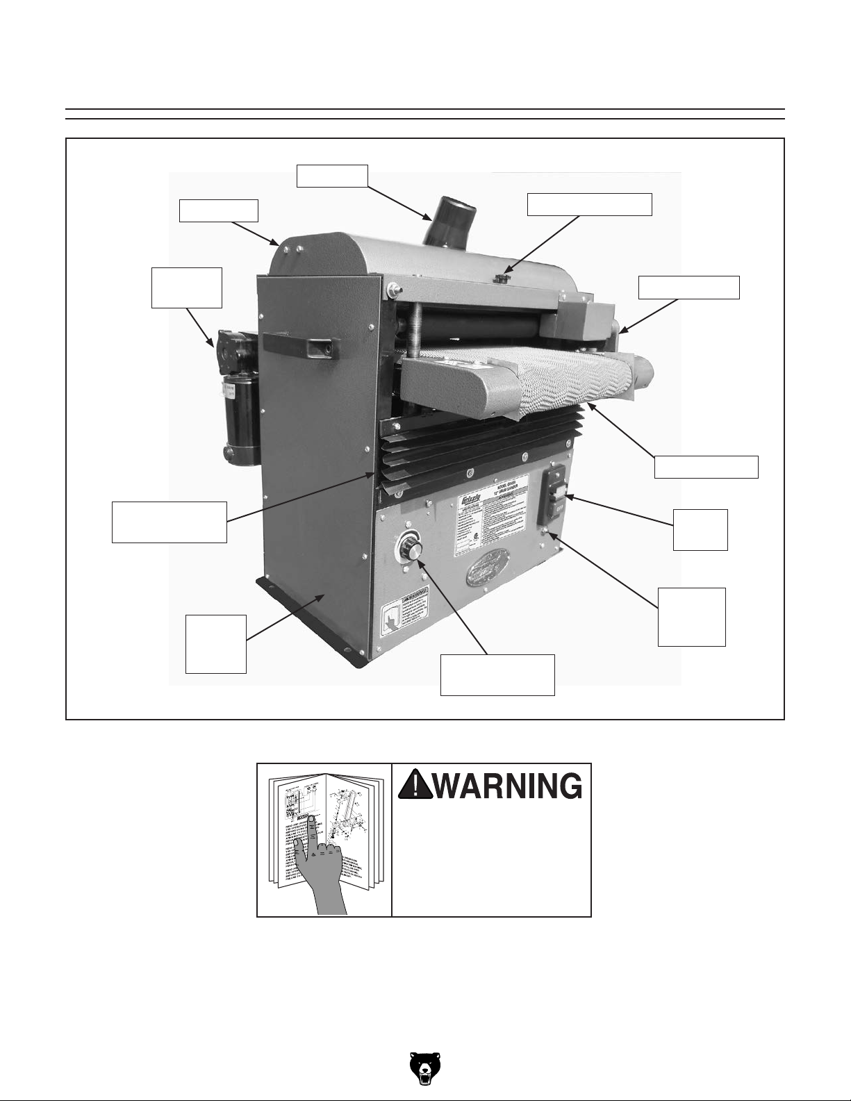
Identification
Dust Port
Top Cover
DC Feed
Motor
Front Elevation
Chain Guard
Drum
Sander
Frame
Cover Lock Knob
Crank Handle
Conveyor Belt
On/Off
Switch
Thermal
Circuit
Breaker
Variable Speed
Control
Model G0459/G0459P (Mfg. 7/11+)
Figure 1. Front view, Model G0459.
To reduce the risk of
serious injury when using
this machine, read and
understand this entire
manual before beginning
any operations.
-3-
Page 6

MACHINE DATA
SHEET
Customer Service #: (570) 546-9663 · To Order Call: (800) 523-4777 · Fax #: (800) 438-5901
MODEL G0459 12" BABY DRUM SANDER
Product Dimensions:
Weight.............................................................................................................................................................. 139 lbs.
Width (side-to-side) x Depth (front-to-back) x Height........................................................................... 27 x 24 x 27 in.
Footprint (Length x Width)..................................................................................................................... 22-1/4 x 12 in.
Shipping Dimensions:
Type..................................................................................................................................................... Cardboard Box
Content........................................................................................................................................................... Machine
Weight.............................................................................................................................................................. 166 lbs.
Length x Width x Height....................................................................................................................... 26 x 27 x 27 in.
Must Ship Upright................................................................................................................................................... Yes
Electrical:
Power Requirement........................................................................................................... 115V, Single-Phase, 60 Hz
Prewired Voltage.................................................................................................................................................. 115V
Full-Load Current Rating..................................................................................................................................... 13.3A
Minimum Circuit Size.............................................................................................................................................. 15A
Connection Type....................................................................................................................................... Cord & Plug
Power Cord Included.............................................................................................................................................. Yes
Power Cord Length............................................................................................................................................... 11 ft.
Power Cord Gauge......................................................................................................................................... 14 AWG
Plug Included.......................................................................................................................................................... Yes
Included Plug Type................................................................................................................................................ 5-15
Switch Type.................................................................................................................... ON/OFF Push Button Switch
Motors:
Main
Type................................................................................................................. TEFC Capacitor-Start Induction
Horsepower............................................................................................................................................. 1.5 HP
Phase............................................................................................................................................ Single-Phase
Amps............................................................................................................................................................ 13A
Speed................................................................................................................................................ 3450 RPM
Power Transfer ............................................................................................................................... V-Belt Drive
Bearings........................................................................................................ Sealed & Permanently Lubricated
Feed
Type..................................................................................................................................................... Universal
Horsepower............................................................................................................................................. 1/8 HP
Phase............................................................................................................................................ Single-Phase
Amps........................................................................................................................................................... 0.3A
Speed.............................................................................................................................................. 5 – 55 RPM
Power Transfer ............................................................................................................................... Direct Drive
Bearings........................................................................................................ Sealed & Permanently Lubricated
-4-
Model G0459/G0459P (Mfg. 7/11+)
Page 7

Main Specifications:
Operation Information
No Of Sanding Heads....................................................................................................................................... 1
Maximum Board Width.............................................................................................................................. 12 in.
Minimum Board Width................................................................................................................................. 2 in.
Maximum Board Thickness................................................................................................................... 3-1/2 in.
Minimum Board Thickness....................................................................................................................... 1/8 in.
Minimum Board Length................................................................................................................................ 8 in.
Sandpaper Speed.............................................................................................................................. 2127 FPM
Conveyor Feed Rate.................................................................................................................. 2.5 – 17.3 FPM
Sandpaper Length..................................................................................................................................... 70 in.
Sandpaper Width......................................................................................................................................... 3 in.
Drum Information
Infeed Sanding Drum Type................................................................................................................. Aluminum
Infeed Sanding Drum Size........................................................................................................................... 4 in.
Construction
Conveyor Belt......................................................................................................................................... Rubber
Body........................................................................................................................................................... Steel
Paint........................................................................................................................................... Powder Coated
Other Related Information
Sanding Belt Tension..................................................................................................................... Hook & Loop
No Of Pressure Rollers..................................................................................................................................... 2
Pressure Roller Type.............................................................................................................................. Rubber
Pressure Roller Size.............................................................................................................................. 1-3/8 in.
Conveyor Belt Length.......................................................................................................................... 49-3/4 in.
Conveyor Belt Width............................................................................................................................ 12-1/4 in.
No Of Dust Ports.............................................................................................................................................. 1
Dust Port Size........................................................................................................................................ 2-1/2 in.
Other Specifications:
Country Of Origin ............................................................................................................................................. Taiwan
Warranty ........................................................................................................................................................... 1 Year
Approximate Assembly & Setup Time ........................................................................................................ 15 Minutes
Serial Number Location .................................................................................................................................. ID Label
ISO 9001 Factory .................................................................................................................................................... No
CSA Certified ......................................................................................................................................................... Yes
Features:
Hoop & Loop Sanding Belt Tension/Sandpaper
Industrial-Duty Rubber Conveyor Belt
2-1/2" Dust Port
Variable Speed Conveyor
V-Belt Main Motor; Direct Drive Feed Motor
4" Aluminum Sanding Drum
Green Powder Coated Paint
Steel Dust Scoop Maximizes Dust Collection Efficiency
Two Adjustable Pressure Rollers
Thickness Scale
Welded Steel Construction
Side Handles for Portability
Model G0459/G0459P (Mfg. 7/11+)
-5-
Page 8

MACHINE DATA
SHEET
Customer Service #: (570) 546-9663 · To Order Call: (800) 523-4777 · Fax #: (800) 438-5901
MODEL G0459P 12" BABY DRUM SANDER, POLAR BEAR
SERIES®
Product Dimensions:
Weight.............................................................................................................................................................. 139 lbs.
Width (side-to-side) x Depth (front-to-back) x Height........................................................................... 27 x 24 x 27 in.
Footprint (Length x Width)..................................................................................................................... 22-1/4 x 12 in.
Shipping Dimensions:
Type..................................................................................................................................................... Cardboard Box
Content........................................................................................................................................................... Machine
Weight.............................................................................................................................................................. 162 lbs.
Length x Width x Height....................................................................................................................... 27 x 26 x 27 in.
Must Ship Upright................................................................................................................................................... Yes
Electrical:
Power Requirement........................................................................................................... 115V, Single-Phase, 60 Hz
Prewired Voltage.................................................................................................................................................. 115V
Full-Load Current Rating..................................................................................................................................... 13.3A
Minimum Circuit Size.............................................................................................................................................. 15A
Connection Type....................................................................................................................................... Cord & Plug
Power Cord Included.............................................................................................................................................. Yes
Power Cord Length............................................................................................................................................... 11 ft.
Power Cord Gauge......................................................................................................................................... 14 AWG
Plug Included.......................................................................................................................................................... Yes
Included Plug Type................................................................................................................................................ 5-15
Switch Type.................................................................................................................... ON/OFF Push Button Switch
Motors:
Main
Type................................................................................................................. TEFC Capacitor-Start Induction
Horsepower............................................................................................................................................. 1.5 HP
Phase............................................................................................................................................ Single-Phase
Amps............................................................................................................................................................ 13A
Speed................................................................................................................................................ 3450 RPM
Power Transfer ............................................................................................................................... V-Belt Drive
Bearings........................................................................................................ Sealed & Permanently Lubricated
Feed
Type..................................................................................................................................................... Universal
Horsepower............................................................................................................................................. 1/8 HP
Phase............................................................................................................................................ Single-Phase
Amps........................................................................................................................................................... 0.3A
Speed.............................................................................................................................................. 5 – 55 RPM
Power Transfer ............................................................................................................................... Direct Drive
Bearings........................................................................................................ Sealed & Permanently Lubricated
-6-
Model G0459/G0459P (Mfg. 7/11+)
Page 9

Main Specifications:
Operation Information
No Of Sanding Heads....................................................................................................................................... 1
Maximum Board Width.............................................................................................................................. 12 in.
Minimum Board Width................................................................................................................................. 2 in.
Maximum Board Thickness................................................................................................................... 3-1/2 in.
Minimum Board Thickness....................................................................................................................... 1/8 in.
Minimum Board Length................................................................................................................................ 8 in.
Sandpaper Speed.............................................................................................................................. 2127 FPM
Conveyor Feed Rate.................................................................................................................. 2.5 – 17.3 FPM
Sandpaper Length..................................................................................................................................... 70 in.
Sandpaper Width......................................................................................................................................... 3 in.
Drum Information
Infeed Sanding Drum Type................................................................................................................. Aluminum
Infeed Sanding Drum Size........................................................................................................................... 4 in.
Construction
Conveyor Belt......................................................................................................................................... Rubber
Body........................................................................................................................................................... Steel
Paint........................................................................................................................................... Powder Coated
Other Related Information
Sanding Belt Tension..................................................................................................................... Hook & Loop
No Of Pressure Rollers..................................................................................................................................... 2
Pressure Roller Type.............................................................................................................................. Rubber
Pressure Roller Size.............................................................................................................................. 1-3/8 in.
Conveyor Belt Length.......................................................................................................................... 49-3/4 in.
Conveyor Belt Width............................................................................................................................ 12-1/4 in.
No Of Dust Ports.............................................................................................................................................. 1
Dust Port Size........................................................................................................................................ 2-1/2 in.
Other Specifications:
Country Of Origin ............................................................................................................................................. Taiwan
Warranty ........................................................................................................................................................... 1 Year
Approximate Assembly & Setup Time ........................................................................................................ 15 Minutes
Serial Number Location ................................................................................................................... ID Label on Front
ISO 9001 Factory .................................................................................................................................................... No
CSA Certified ......................................................................................................................................................... Yes
Features:
Hoop & Loop Sanding Belt Tension/Sandpaper
Industrial-Duty Rubber Conveyor Belt
2-1/2" Dust Port
Variable Speed Conveyor
V-Belt Main Motor; Direct Drive Feed Motor
4" Aluminum Sanding Drum
White Powder Coated Paint
Steel Dust Scoop Maximizes Dust Collection Efficiency
Two Adjustable Pressure Rollers
Thickness Scale
Welded Steel Construction
Side Handles for Portability
Model G0459/G0459P (Mfg. 7/11+)
-7-
Page 10

SECTION 1: SAFETY
For Your Own Safety, Read Instruction
Manual Before Operating This Machine
The purpose of safety symbols is to attract your attention to possible hazardous conditions.
This manual uses a series of symbols and signal words intended to convey the level of importance of the safety messages. The progression of symbols is described below. Remember that
safety messages by themselves do not eliminate danger and are not a substitute for proper
accident prevention measures. Always use common sense and good judgment.
Indicates an imminently hazardous situation which, if not avoided,
WILL result in death or serious injury.
Indicates a potentially hazardous situation which, if not avoided,
COULD result in death or serious injury.
Indicates a potentially hazardous situation which, if not avoided,
MAY result in minor or moderate injury. It may also be used to alert
against unsafe practices.
This symbol is used to alert the user to useful information about
NOTICE
proper operation of the machine.
Safety Instructions for Machinery
OWNER’S MANUAL. Read and understand this
owner’s manual BEFORE using machine.
TRAINED OPERATORS ONLY. Untrained operators have a higher risk of being hurt or killed.
Only allow trained/supervised people to use this
machine. When machine is not being used, disconnect power, remove switch keys, or lock-out
machine to prevent unauthorized use—especially
around children. Make workshop kid proof!
DANGEROUS ENVIRONMENTS. Do not use
machinery in areas that are wet, cluttered, or have
poor lighting. Operating machinery in these areas
greatly increases the risk of accidents and injury.
MENTAL ALERTNESS REQUIRED. Full mental
alertness is required for safe operation of machinery. Never operate under the influence of drugs or
alcohol, when tired, or when distracted.
ELECTRICAL EQUIPMENT INJURY RISKS. You
can be shocked, burned, or killed by touching live
electrical components or improperly grounded
machinery. To reduce this risk, only allow qualified
service personnel to do electrical installation or
repair work, and always disconnect power before
accessing or exposing electrical equipment.
DISCONNECT POWER FIRST.
nect machine from power supply BEFORE making
adjustments, changing tooling, or servicing machine.
This prevents an injury risk from unintended startup
or contact with live electrical components.
EYE PROTECTION. Always wear ANSI-approved
safety glasses or a face shield when operating or
observing machinery to reduce the risk of eye
injury or blindness from flying particles. Everyday
eyeglasses are not approved safety glasses.
Always discon-
-8-
Model G0459/G0459P (Mfg. 7/11+)
Page 11

WEARING PROPER APPAREL. Do not wear
clothing, apparel or jewelry that can become
entangled in moving parts. Always tie back or
coverlong hair.Wearnon-slip footwearto avoid
accidentalslips,whichcouldcauselossofworkpiececontrol.
hAzARdOus dusT. Dust created while using
machinery may cause cancer, birth defects, or
long-term respiratory damage. Beaware ofdust
hazardsassociatedwitheachworkpiecematerial,
andalwayswearaNIOSH-approvedrespiratorto
reduceyourrisk.
hEARING PROTECTION. Always wear hearing protectionwhen operating or observingloud
machinery. Extended exposure to this noise
withouthearing protectioncan causepermanent
hearingloss.
REMOVE AdJusTING TOOLs. Tools left on
machinery can become dangerous projectiles
uponstartup.Neverleavechuckkeys,wrenches,
or any other tools on machine. Always verify
removalbeforestarting!
INTENdEd usAGE. Only use machine for its
intendedpurposeand never makemodifications
not approved by Grizzly. Modifying machine or
using it differently than intended may result in
malfunctionormechanicalfailurethatcanleadto
seriouspersonalinjuryordeath!
AWKWARd POsITIONs. Keep proper footing
andbalanceatalltimeswhenoperatingmachine.
Donotoverreach!Avoidawkwardhandpositions
that makeworkpiece control difficult orincrease
the
riskofaccidentalinjury.
ChILdREN & BYsTANdERs. Keepchildrenand
bystandersatasafedistancefromtheworkarea.
Stopusingmachineiftheybecomeadistraction.
FORCING MAChINERY.Donot force machine.
Itwill dothe jobsafer andbetter at the rate for
whichitwasdesigned.
NEVER sTANd ON MAChINE. Serious injury
may occur if machine is tipped or if the cutting
toolisunintentionallycontacted.
sTABLE MAChINE. Unexpectedmovementduring operation greatly increases risk of injury or
lossofcontrol.Beforestarting,verifymachineis
stableandmobilebase(ifused)islocked.
usE RECOMMENdEd ACCEssORIEs.Consult
thisowner’smanualorthemanufacturerforrecommended accessories. Usingimproper accessorieswillincreasetheriskofseriousinjury.
uNATTENdEd OPERATION. To reduce the
risk of accidentalinjury, turn machine off and
ensure all moving parts completely stop before
walking away. Never leave machine running
whileunattended.
MAINTAIN WITh CARE.Followallmaintenance
instructions and lubrication schedules to keep
machine in good working condition. A machine
that is improperly maintained could malfunction,
leading
ChECK dAMAGEd PARTs. Regularly inspect
machine for any condition that may affect safe
operation.Immediatelyrepairorreplacedamaged
ormis-adjustedpartsbeforeoperatingmachine.
MAINTAIN POWER CORds. When disconnecting cord-connected machines from power, grab
andpulltheplug—NOTthecord.Pullingthecord
may damage the wires inside. Do not handle
cord/plug with wethands.Avoidcord damageby
keepingitawayfromheatedsurfaces,hightraffic
areas,harshchemicals,andwet/damplocations.
toseriouspersonalinjuryordeath.
GuARds & COVERs.Guardsandcoversreduce
accidental contact with moving parts or flying
debris. Make sure they are properly installed,
undamaged,andworkingcorrectly.
Model G0459/G0459P (Mfg. 7/11+)
EXPERIENCING dIFFICuLTIEs. If at any time
youexperiencedifficultiesperformingtheintendedoperation,stopusingthemachine!Contactour
TechnicalSupportat(570)546-9663.
-9-
Page 12

Additional Safety for Drum Sanders
FEEDING STOCK. Do not stand in the direct
path of a workpiece at the infeed end when feeding your stock. Never sand more than one piece
of stock at a time. DO NOT jam the workpiece
into the machine during operation. Firmly grasp
the workpiece in both hands and ease it into the
machine using light pressure.
MINIMUM STOCK DIMENSIONS. Do not sand
any stock thinner than
shorter than 8". Do not sand thin stock by using a
“dummy” board under your workpiece.
SAFETY COVERS. All covers must be closed
and in place before starting machine.
CLOTHING. Do not wear loose clothing while
operating this machine. Roll up or button long
sleeves at the cuff.
HAND PROTECTION. Do not place hands near,
or in contact with, sanding drum during operation.
DO NOT allow fingers to get pinched between
board and conveyor belt during operation. This
may pull the operator’s hand into the machine and
cause serious injury!
DUST COLLECTION SYSTEM. Never operate
the sander without an adequate dust collection
system in place and running.
1
⁄8", narrower than 2", or
INSPECTING WORKPIECES. Always inspect
every workpiece for nails, staples, knots, and
other imperfections that could be dislodged and
thrown from the machine during sanding operations. Do not use workpieces with these defects.
EXPERIENCING DIFFICULTIES. Any problem,
with the exception of conveyor belt tracking, that
is concerned with any moving parts or accessories, must be investigated and corrected with the
power disconnected, and after all moving parts
have come to a complete stop.
MAINTENANCE AND ADJUSTMENTS. Never
attempt to adjust conveyor belt tracking when the
sanding drum is running.
Perform machine inspections and maintenance
service promptly when called for. Disconnect
power before performing maintenance or adjustments to the sander.
RESPIRATOR AND SAFETY GLASSES. Always
wear a respirator and safety glasses while operating the machine. Dust and chips are created when
sanding. Some debris will be ejected, becoming
hazards to the eyes and lungs.
-10 -
Model G0459/G0459P (Mfg. 7/11+)
Page 13

SECTION 2: POWER SUPPLY
Before installing the machine, consider the availability and proximity of the required power supply
circuit. If an existing circuit does not meet the
requirements for this machine, a new circuit must
be installed. To minimize the risk of electrocution,
fire, or equipment damage, installation work and
electrical wiring must be done by an electrican or
qualified service personnel in accordance with all
applicable codes and standards.
Electrocution, fire, or
equipment damage may
occur if machine is not
correctly grounded and
connected to the power
The full-load current rating is the amperage a
machine draws at 100% of the rated output power.
On machines with multiple motors, this is the
amperage drawn by the largest motor or sum of all
motors and electrical devices that might operate
at one time during normal operations.
The full-load current is not the maximum amount
of amps that the machine will draw. If the machine
is overloaded, it will draw additional amps beyond
the full-load rating.
If the machine is overloaded for a sufficient length
of time, damage, overheating, or fire may result—
especially if connected to an undersized circuit.
To reduce the risk of these hazards, avoid overloading the machine during operation and make
sure it is connected to a power supply circuit that
meets the requirements in the following section.
For your own safety and protection of
Note: The circuit requirements listed in this manual apply to a dedicated circuit—where only one
machine will be running at a time. If this machine
will be connected to a shared circuit where multiple machines will be running at the same time,
consult a qualified electrician to ensure that the
circuit is properly sized for safe operation.
A power supply circuit includes all electrical
equipment between the breaker box or fuse panel
in the building and the machine. The power supply circuit used for this machine must be sized to
safely handle the full-load current drawn from the
machine for an extended period of time. (If this
machine is connected to a circuit protected by
fuses, use a time delay fuse marked D.)
This machine is prewired to operate on a 115V
power supply circuit that has a verified ground and
meets the following requirements:
Availability
supply.
Full-Load Current Rating
Circuit Requirements
Nominal Voltage ........................................ 115V
Cycle .......................................................... 60 Hz
Phase ........................................... Single-Phase
Power Supply Circuit ......................... 15 Amps
property, consult an electrician if you are
unsure about wiring practices or electrical
codes in your area.
Full-Load Current Rating at 115V... 13.3 Amps
Model G0459/G0459P (Mfg. 7/11+)
-11-
Page 14
Improper connection of the equipment-grounding
wire can result in a risk of electric shock. The
wire with green insulation (with or without yellow
stripes) is the equipment-grounding wire. If repair
or replacement of the power cord or plug is necessary, do not connect the equipment-grounding
wire to a live (current carrying) terminal.
Check with a qualified electrician or service personnel if you do not understand these grounding
requirements, or if you are in doubt about whether
the tool is properly grounded. If you ever notice
that a cord or plug is damaged or worn, disconnect it from power, and immediately replace it with
a new one.
We do not recommend using an extension cord
with this machine.
cord, only use it if absolutely necessary and only
on a temporary basis.
Extension cords cause voltage drop, which may
damage electrical components and shorten motor
life. Voltage drop increases as the extension cord
size gets longer and the gauge size gets smaller
(higher gauge numbers indicate smaller sizes).
Any extension cord used with this machine must
contain a ground wire, match the required plug
and receptacle, and meet the following requirements:
Grounding & Plug Requirements
Serious injury could occur if you connect
it will not fit the outlet, have a qualified
electrician install the proper outlet with a
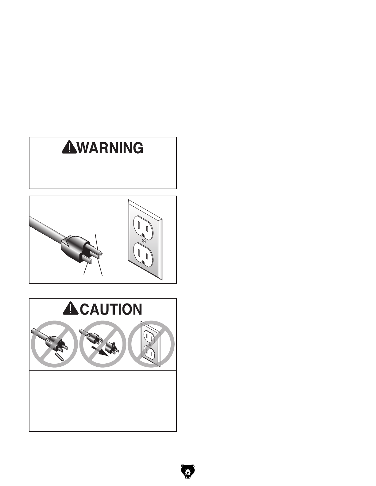
This machine MUST be grounded. In the event
of certain malfunctions or breakdowns, grounding
reduces the risk of electric shock by providing a
path of least resistance for electric current.
This machine is equipped with a power cord that
has an equipment-grounding wire and a grounding plug (similar to the figure below). The plug
must only be inserted into a matching receptacle
(outlet) that is properly installed and grounded in
accordance with all local codes and ordinances.
the machine to power before completing the
setup process. DO NOT connect to power
until instructed later in this manual.
GROUNDED
5-15 RECEPTACLE
Grounding Prong
5-15 PLUG
Neutral Hot
Figure 2. Typical 5-15 plug and receptacle.
Extension Cords
If you must use an extension
Minimum Gauge Size ...........................14 AWG
Maximum Length (Shorter is Better).......50 ft.
Two-prong outlets do not meet the grounding
requirements for this machine. Do not modify
or use an adapter on the plug provided—if
verified ground.
-12-
SHOCK HAZARD!
Model G0459/G0459P (Mfg. 7/11+)
Page 15

SECTION 3: SETUP
Your machine was carefully packaged for safe
transportation. Remove the packaging materials
from around your machine and inspect it. If you
discover any damage, please call us immediately
at (570) 546-9663
Save the containers and all packing materials for
possible inspection by the carrier or its agent.
Otherwise, filing a freight claim can be difficult.
When you are completely satisfied with the condition of your shipment, inventory the contents.
The following is a list of items shipped with your
machine. Before beginning setup, lay these items
out and inventory them.
If any non-proprietary parts are missing (e.g. a
nut or a washer), we will gladly replace them; or
for the sake of expediency, replacements can be
obtained at your local hardware store.
To reduce your risk of
serious injury, read this
entire manual BEFORE
using machine.
Wear safety glasses during the entire setup process!
This machine and its components are very heavy.
Get lifting help or use
power lifting equipment
such as a forklift to move
heavy items.
Unpacking
for advice.
Inventory
Needed for Setup
The following are needed to complete the setup
process, but are not included with your machine.
Description Qty
• Safety Glasses ........................................... 1
• Additional People ....................................... 1
• Screwdriver Phillips #2 ............................... 1
• Dust Collection System .............................. 1
• Dust Hose 2
• Hose Clamps 2
• Lag Bolts
• Open End Wrench or Socket
• Drill ............................................................. 1
• Drill Bit
Model G0459/G0459P (Mfg. 7/11+)
1
⁄2" ........................................... 1
1
⁄2" ...................................... 2
5
⁄16 -18 x 40 (Not Included) .......... 4
1
⁄4” ................................................... 1
1
⁄2 ” ................ 1
Box 1: (Figure 3) Qty
A. Drum Sander (not shown) .......................... 1
B. Crank Handle ............................................. 1
C. Dust Port 2
D. Hex Wrench 3mm ....................................... 1
Figure 3. G0459/G0459P Inventory.
1
⁄2 " ............................................. 1
B
C
D
NOTICE
If you cannot find an item on this list, carefully check around/inside the machine and
packaging materials. Often, these items get
lost in packaging materials while unpacking or they are pre-installed at the factory.
-13-
Page 16
Site Considerations
Weight Load
Physical Environment
Place this machine near an existing power source.
Shadows, glare, or strobe effects that may distract
Refer to the Machine Data Sheet for the weight
of your machine. Make sure that the surface upon
which the machine is placed will bear the weight
of the machine, additional equipment that may be
installed on the machine, and the heaviest workpiece that will be used. Additionally, consider the
weight of the operator and any dynamic loading
that may occur when operating the machine.
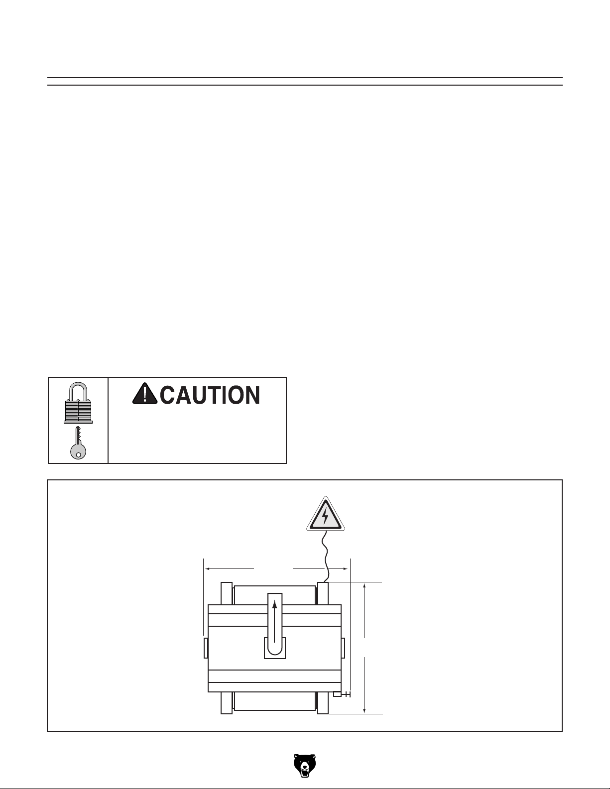
Space Allocation
Consider the largest size of workpiece that will
be processed through this machine and provide
enough space around the machine for adequate
operator material handling or the installation of
auxiliary equipment. With permanent installations,
leave enough space around the machine to open
or remove doors/covers as required by the maintenance and service described in this manual.
See below for required space allocation.
Children or untrained people
may be seriously injured by
this machine. Only install in an
access restricted location.
The physical environment where the machine is
operated is important for safe operation and longevity of machine components. For best results,
operate this machine in a dry environment that is
free from excessive moisture, hazardous chemicals, airborne abrasives, or extreme conditions.
Extreme conditions for this type of machinery are
generally those where the ambient temperature
range exceeds 41°–104°F; the relative humidity
range exceeds 20–95% (non-condensing); or the
environment is subject to vibration, shocks, or
bumps.
Electrical Installation
Make sure all power cords are protected from
traffic, material handling, moisture, chemicals,
or other hazards. Make sure to leave access to
a means of disconnecting the power source or
engaging a lockout/tagout device, if required.
Lighting
Lighting around the machine must be adequate
enough that operations can be performed safely.
or impede the operator must be eliminated.
-14-
261/2"
24"
Figure 4. Minimum working clearances.
Model G0459/G0459P (Mfg. 7/11+)
Page 17
Mounting
The base of this machine has holes that allow
it to be mounted to a workbench. We strongly
recommend that you mount your machine to
a workbench to prevent it from moving during
operation. An unexpected movement could result
in an injury or property damage.
The strongest mounting option is a "Through
Mount" where holes are drilled all the way through
the workbench, and hex bolts, washers, and hex
nuts are used to secure the drum sander to the
workbench.
Hex
Bolt
Flat Washer
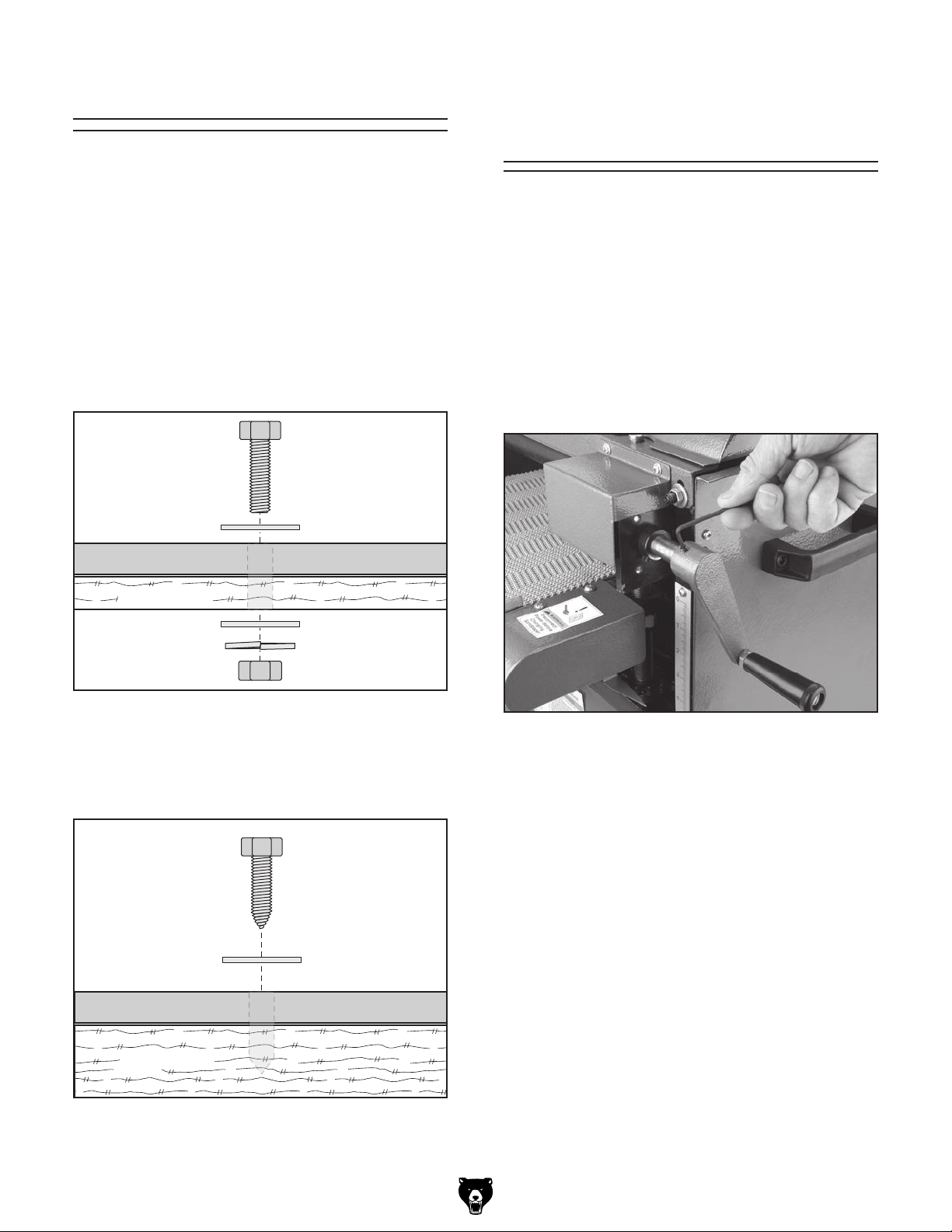
Installing Crank
Handle
Components and Hardware Needed: Qty
Crank Handle .................................................... 1
The crank handle is installed on the front right
lift screw shaft, and is held in place with two set
screws already threaded into the handle.
To mount the handwheel, place the crank handle
over the shaft shown in Figure 7 and, using a
3mm hex wrench, secure the handle with the two
set screws.
Machine Base
Workbench
Flat Washer
Lock Washer
Hex Nut
Figure 5. Example of a through mount setup.
Another option for mounting is a "Direct Mount"
where the machine is simply secured to the workbench with a lag screw.
Lag Screw
Flat Washer
Machine Base
Figure 7. Crank handle installation.
Workbench
Figure 6. Example of a direct mount setup.
Model G0459/G0459P (Mfg. 7/11+)
-15-
Page 18
Dust Collection
After you have completed all previous setup
instructions and circuit requirements, the machine
is ready to be connected to the power supply.
To avoid unexpected startups or property damage, use the following steps whenever connecting
or disconnecting the machine.
1. TurnthemachinepowerswitchOFF.
2.
matching
is
1. TurnthemachinepowerswitchOFF.
2.
completely
cord
DO NOT operate the Model G0459/G0459P
without an adequate dust collection system.
This sander creates substantial amounts of
wood dust while operating. Failure to use a
dust collection system can result in short
and long-term respiratory illness.
Recommended CFM at Dust Port: 150 CFM
Do not confuse this CFM recommendation with
the rating of the dust collector. To determine the
CFM at the dust port, you must consider these
variables: (1) CFM rating of the dust collector,
(2) hose type and length between the dust collector and the machine, (3) number of branches
or wyes, and (4) amount of other open lines
throughout the system. Explaining how to calculate these variables is beyond the scope of
this manual. Consult an expert or purchase a
good dust collection "how-to" book.
Power Connection
Connecting Power
Insert the power cord plug into a
power supply receptacle. The machine
nowconnectedtothepowersource.
To connect a dust collection hose:
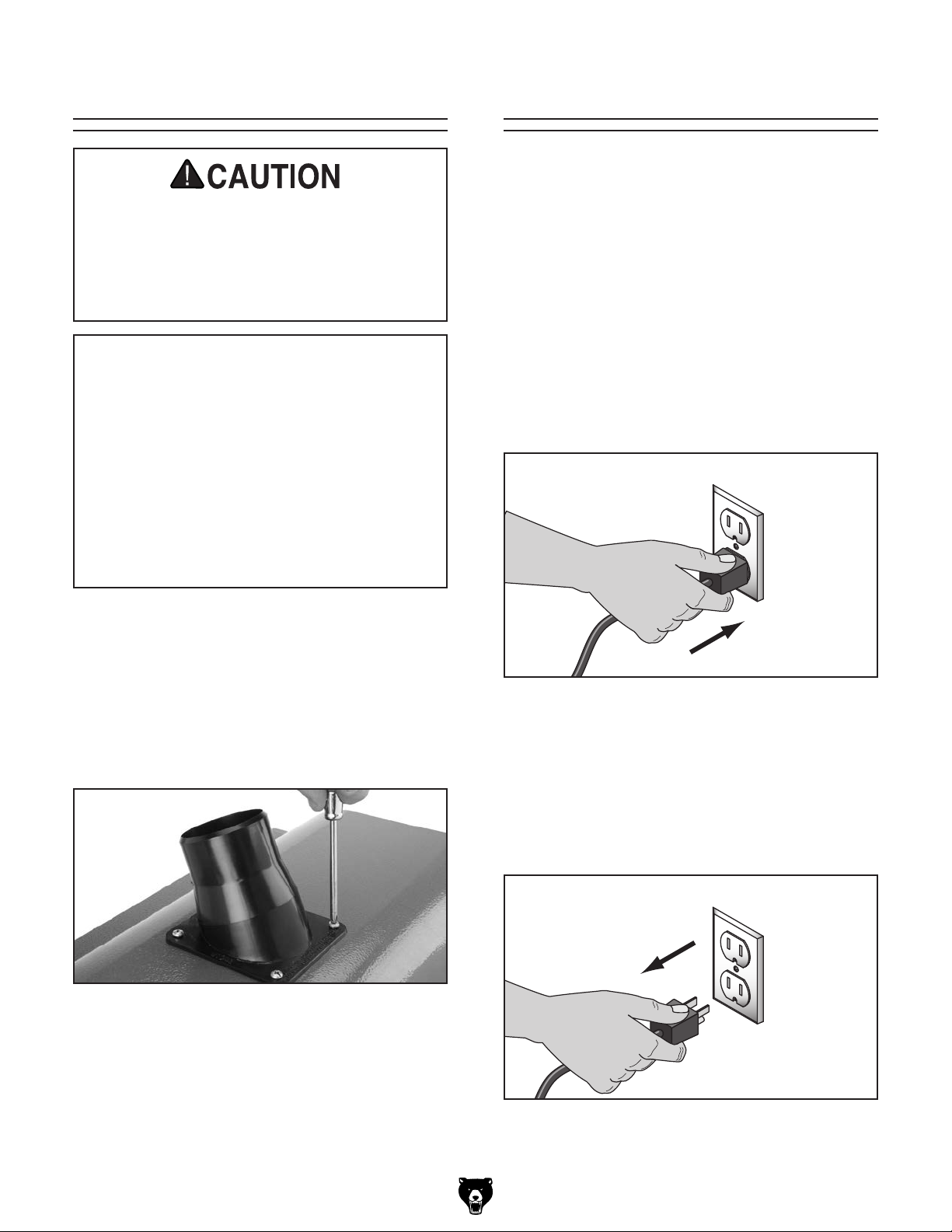
1. Remove the four Phillips head screws at the
dust port hole.
1
2. Place the 2
mounting holes and secure with the screws
removed in Step 1 (see Figure 8).
Figure 8. Dust port installation.
3. Fit a 21⁄2" dust hose over the dust port and
secure in place with a hose clamp.
⁄2" dust port over the top cover
Figure 9. Connecting power.
Disconnecting Power
Graspthemoldedplugandpullit
outofthereceptacle.Donotpullbythe
asthismaydamagethewiresinside.
4. Tug the hose to make sure it does not come
off. Note: A tight fit is necessary for proper
performance.
-16 -
Figure 10. Disconnecting power.
Model G0459/G0459P (Mfg. 7/11+)
Page 19

Test Run
Once the assembly is complete, test run your
machine to make sure it runs properly.
If, during the test run, you cannot easily locate
the source of an unusual noise or vibration, stop
using the machine immediately, then review the
Troubleshooting on Manual Page 23.
If you still cannot remedy a problem, contact our
Tech Support at (570) 546-9663 for assistance.
To test run the machine:
Recommended
Adjustments
For your convenience, the adjustments listed
below have been performed at the factory and
no further setup is required to operate your
machine.
However, because of the many variables involved
with shipping, some of these adjustments may
need to be repeated to ensure optimum results.
Keep this in mind as you start to use your new
drum sander.
1. Make sure you have read the safety instructions at the beginning of the manual and that
the machine is setup properly.
2. Make sure all tools and objects used during
setup are cleared away from the machine.
3. Turn the machine ON, then rotate the vari-
able speed knob clockwise to start the conveyor belt.
4. Listen to and watch for abnormal noises or
actions. The machine should run smoothly
with little or no vibration or rubbing noises.
— Strange or unusual noises should be inves-
tigated and corrected before operating the
machine further. Always disconnect the
machine from power when investigating or
correcting potential problems.
5. Turn the machine OFF.
Step-by-step instructions for these adjustments can be found in SECTION 7: SERVICE
ADJUSTMENTS.
1. V-Belt Service (Page 30). Perform after the
first 16 hours.
2. Conveyor Tensioning & Tracking (Page 32).
3. Drum Adjustments (Page 33).
4. Pressure Roller Height (Page 35).
Model G0459/G0459P (Mfg. 7/11+)
-17-
Page 20

SECTION 4: OPERATIONS
The purpose of this overview is to provide the novice machine operator with a basic understanding
of how the machine is used during operation, so
the
discussed later
in this manual
Due to the generic nature of this overview, it is
not
more about specific operations,
manual and
rienced
research outside of this manual by reading "howto" books, trade magazines, or websites.
To reduce your risk of
serious injury, read this
entire manual BEFORE
To reduce risk of eye injury from flying
Operation Overview
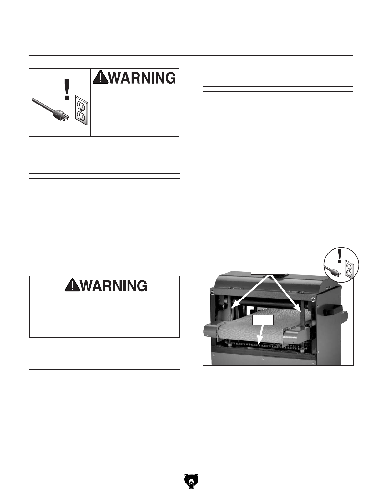
To complete a typical operation, the operator
does the following:
1. Examines the workpiece to make sure it is
suitable for sanding.
machine controls/components
are easier to understand.
intended to be an instructional guide. To learn
read this entire
seek additional training from expe-
machine operators, and do additional
using machine.
chips or lung damage from breathing dust,
always wear safety glasses and a respirator
when operating this machine.
2. Places the workpiece on the conveyor table
under or next to the front pressure roller, and
adjusts the table height until the top surface
of the workpiece just touches the front pressure roller.
3. Checks the outfeed side of the machine to
make sure the workpiece can safely pass all
the way through without interference from
other objects.
4. Wears safety glasses and a respirator.
5. Starts the dust collector.
6. Turns the sander ON, adjusts conveyor
speed, places the workpiece flat on the
conveyor, then lets the conveyor feed the
workpiece into the sander.
7. Slowly raises the conveyor table using the
hand crank until the sandpaper begins sanding the workpiece.
8. Stands at the side of the sander and retrieves
the workpiece from the outfeed end.
If you are not experienced with this type
of machine, WE STRONGLY RECOMMEND
that you seek additional training outside of
this manual. Read books/magazines or get
formal training before beginning any projects. Regardless of the content in this section, Grizzly Industrial will not be held liable
for accidents caused by lack of training.
-18-
9. Stops the machine.
Model G0459/G0459P (Mfg. 7/11+)
Page 21

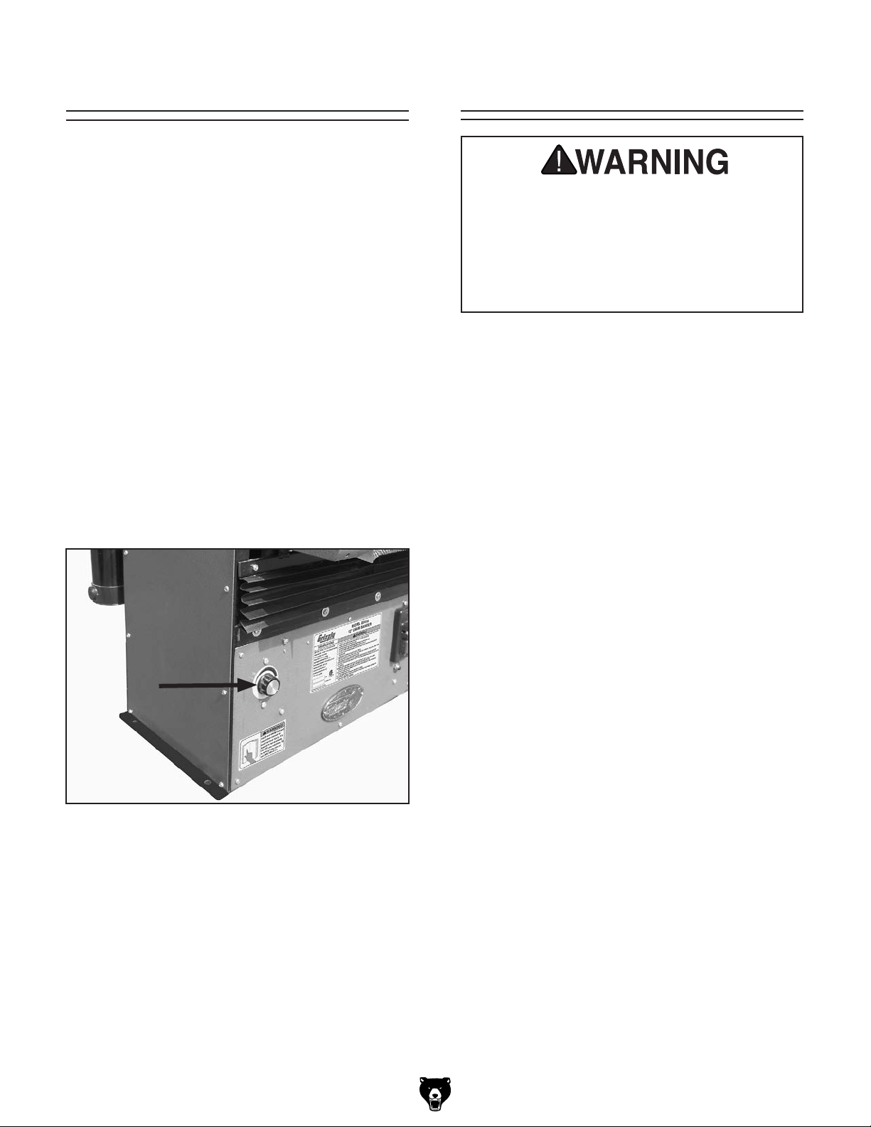
Basic Controls
Children or untrained people can be
. This
To help prevent unsupervised operation,
The ON/OFF switch can be disabled and locked
by inserting a padlock through the ON button,
as shown. Locking the switch in this manner can
prevent unauthorized operation of the machine,
which is especially important if the machine is not
stored inside an access-restricted building.
IMPORTANT:
only restricts its function. It is not a substitute
for disconnecting power from the machine when
adjusting or servicing.
Refer to Figure 11 and the following descriptions
to become familiar with the basic controls of this
machine.
A. Variable Speed Knob: Adjusts feed rate
from 2.47–17.3 FPM. Rotate clockwise to
increase feed speed, rotate counterclockwise
to decrease feed speed.
Disabling & Locking
Switch
B. Hand Crank: Used to raise or lower the con-
veyor table to control depth of cut. Each full
rotation of the hand crank raises or lowers the
conveyor table approximately 0.027" (0.69
mm).
C. On Button: Turns motor ON.
D. Off Button: Turns motor OFF.
A
Figure 11. G0459/G0459P controls.
Locking the switch with a padlock
Padlock
Shaft
B
Figure 12. Switch disabled by a padlock.
C
D
seriously injured by this machine
risk increases with unsupervised operation.
disable and lock the switch before leaving
machine unattended! Place key in a wellhidden or secure location.
Model G0459/G0459P (Mfg. 7/11+)
NOTICE
The padlock shaft diameter is important to
the disabling function of the switch. With
any padlock used to lock the switch, test
the switch after installation to ensure that it
is properly disabled.
Figure 13. Minimum lock shaft requirements.
-19 -
Page 22

Sanding Tips
• Replace the sandpaper with a higher grit to
achieve a finer finish.
1
• Raise the table with a maximum of
the crank handle until the workpiece is the
desired thickness.
⁄4 turn of
Stock Inspection and
Requirements
Some workpieces are not safe or may require
modification before they are safe to sand. Before
sanding, inspect all workpieces for the following:
• Reduce snipe when sanding more than one
board of the same thickness by feeding them
into the sander with the front end of the second board touching the back end of the first
board.
• Feed boards into the sander at different points
on the conveyor to maximize sandpaper life
and prevent uneven conveyor belt wear.
• DO NOT sand boards less than 8" long or
less than
workpiece and the drum sander.
• Extend the life of the sandpaper by regularly
using a PRO-STICK
24).
• When sanding workpieces with irregular surfaces, such as cabinet doors, take very light
sanding passes to prevent gouges. When
the drum moves from sanding a wide surface
to sanding a narrow surface, the load on
the motor will be reduced, and the drum will
speed up, causing a gouge.
1
⁄8" thick to prevent damage to the
®
sanding pad (Page
• Material Type: This machine is intended for
ONLY sanding natural and man-made wood
products. This machine is NOT designed
to sand metal, glass, stone, tile, drywall or
cementitious backerboard.
• Foreign Objects: Nails, staples, dirt, rocks
and other foreign objects are often embedded in wood. While sanding, these objects
can become dislodged and tear the sandpaper. Always visually inspect your workpiece
for these items. If they can't be removed, DO
NOT sand the workpiece.
• Excessive glue or finish: Sanding
workpieces with excess glue or finish will load
up the abrasive, reducing its usefulness and
lifespan.
• Workpiece Dimensions: DO NOT sand
boards less than 8" long, 2" wide and
thick to prevent damage to the workpiece to
reduce the risk of your hands contacting the
sandpaper (see Figure 14).
1
⁄8"
• DO NOT edge sand boards. This can cause
boards to kickback, causing serious personal
injury. Edge sanding boards also can cause
damage to the conveyor belt and sandpaper.
• When sanding workpieces with a bow or
crown, place the high point up (prevents the
workpiece from rocking) and take very light
passes.
• Feed the workpiece at an angle to maximize
stock removal and sandpaper effectiveness,
but feed the workpiece straight to reduce
sandpaper grit scratches for the finish passes.
-20-
8" Min.
1
⁄8" Min.
2" Min.
Figure 14. Minimum dimensions for sanding.
Model G0459/G0459P (Mfg. 7/11+)
Page 23

Depth of Cut
The optimum depth of cut will vary based on
the type of wood, feed rate, and sandpaper grit.
Under most sanding conditions, the depth should
not exceed 0.006" (0.15 mm) (approx.
the handwheel). Each full turn of the crank handle
raises the conveyor table approximately 0.027"
(0.69 mm). Attempts to remove too much material
can cause jamming, wood burning, rapid paper
wear or tearing, poor finish, belt slippage, and
motor damage.
To set the depth of cut:
1. Rotate the crank handle (Figure 15) until
the conveyor table is well below the sanding
drum, place the workpiece on the table, then
raise the table, until the front pressure roller
just touches the top of the workpiece.
Note: When adjusting the table to sand a
thicker workpiece, lower and then raise the
table to remove backlash from the adjustment mechanism. If the table is lowered too
far, the conveyor belt may rub against the
chain, leaving grease on the belt.
1
⁄4 turn of
Crank
Handle
Figure 15. Setting depth of cut.
2. Turn the sander ON, start the conveyor (see
Variable Speed on Page 22), and feed the
workpiece into the sander. SLOWLY raise
the conveyor table until the workpiece makes
light contact with the sanding drum. This
is the correct height to begin sanding the
workpiece.
Model G0459/G0459P (Mfg. 7/11+)
-21-
Page 24
The variable speed knob allows you to increase
the feed rate from 2.47–17.3 FPM. The correct
speed to use depends on the type of stock you
are using (hardwood vs. softwood) and the stage
of finish you are at with that workpiece.
As a general rule, a slower feed rate sands the
surface smoother, but runs the risk of burning the
wood; a faster feed rate removes material faster,
but runs the risk of overloading the motor.
Use trial-and-error to determine the best settings
for your specific applications.
SandingVariable Speed
DO NOT sand more than one board at a time.
Minor variations in thickness can cause one
board to be propelled by the rapidly spinning
sanding drum and ejected from the machine.
NEVER stand directly in front of the outfeed
area of the machine. Failure to do so could
result in severe personal injury.
To sand a workpiece:
To adjust the conveyor speed:
1. Start the conveyor.
2. Rotate the variable speed knob (Figure
16) clockwise to increase the feed speed,
or counterclockwise to decrease the feed
speed.
1. Adjust the table height according to the
instructions in Depth of Cut on Page 21.
2. Start the dust collector, turn the sander ON,
and start the conveyor.
3. Feed the workpiece through the sander.
Retrieve the workpiece by standing at the
side—not at the outfeed end.
4. Run wide stock through two or three times
without adjusting the table height. Turn the
stock 180° between passes to ensure an
even cut.
-22-
Figure 16. Variable speed knob.
Model G0459/G0459P (Mfg. 7/11+)
Page 25

70"
12 3/
4
"
12 3/
4
"
3"
Choosing Sandpaper
There are many types of sanding belts to choose
from. We recommend aluminum oxide for general workshop environments. Below is a chart
that groups abrasives into different classes, and
shows which grits fall into each class.
Grit Class Usage
36 Extra Coarse Rough sawn boards,
thickness sanding,
and glue removal.
60 Coarse Thickness sanding
and glue removal.
80–100 Medium Removing planer
marks and initial finish
sanding.
120 –180 Fine Finish sanding.
The general rule of thumb is to sand a workpiece
with progressively higher grit numbers, with no
one grit increase of more than 50. Avoid skipping
grits; the larger the grit increase, the harder it will
be to remove the scratches from the previous
grit.
Ultimately, the type of wood you use and your
stage of finish will determine the best grit types to
install on your sander.
4. Use the old sandpaper as a pattern to cut
out the new sandpaper, or use the pattern in
Figure 17, to cut the sandpaper to the neces-
sary shape.
Figure 17. Sandpaper pattern.
5. Wrap the sanding drum with the new sandpa-
per. Make sure to wrap the sandpaper tight
and try to keep the gaps to a minimum.
3
6. Tape both ends with
(Figure 18), making at least two complete
passes so that the second layer is directly on
top of the first.
⁄4" strapping tape
Paper Replacement
The Model G0459/G0459P is designed for 3"
wide hook-and-loop sandpaper rolls.
To change sandpaper:
1. DISCONNECT POWER TO THE SANDER!
2. Open the top cover to expose the drum.
3. Unwind the old sandpaper and notice the
direction that it was wrapped around the
drum.
Model G0459/G0459P (Mfg. 7/11+)
Figure 18. Sandpaper ends taped on
Model G0459.
-23-
Page 26

SECTION 5: ACCESSORIES
Some aftermarket accessories can be
installed on this machine that could cause
it to function improperly, increasing the risk
of serious personal injury. To minimize this
risk, only install accessories recommended
for this machine by Grizzly.
NOTICE
Refer to the newest copy of the Grizzly
Catalog for other accessories available for
this machine.
Aluminum Oxide Hook & Loop Sanding Rolls,
3" x 50'
H4422—60 Grit: Use for thickness sanding and
glue removal.
H4779—80 Grit: Use for removing planer marks
and initial finish sanding.
H4423—100 Grit: Use for removing planer marks
and initial finish sanding.
H4780—120 Grit: Use for finish sanding.
H4424—150 Grit: Use for finish sanding.
H1052—Clear Flexible Hose 4” x 10’
G3124—Wire Hose Clamps - 2
G3123—Flexible Hose - 2
Everything you need to hook your sander up to a
dust collector.
G3119 — 4" x 2
Made with Anti-Static Additive! Made in USA.
G4679—Anti-Static Grounding Kit
We've hand picked a selection of commonly used
dust collection components for machines with 4"
dust ports.
G1843—4" Plastic Blast Gate
H1052
G1843
Figure 19. Dust collection accessories.
1
⁄2" Adapter
G3124
G4679
1
1
⁄2" x 10'
G3123
⁄2"
G3119
PRO-STICK® Sanding Pad
Extend the life of your sandpaper! Just feed this
crepe-rubber cleaning pad through your drum
sander to remove dust build-up from the sandpaper without damage.
Size Model
12" X 15" X
-24-
3
⁄4" ........................................ H7331
G1163—1HP Dust Collector
Effective dust collection not only keeps your shop
cleaner and more pleasant to work in, it can also
keep you healthier. 1HP motor, 450 CFM, 2 cubic
feet bag capacity, 13
intake hole make this a great companion to your
new sander!
Figure 20. Model G1163 Dust Collector.
Model G0459/G0459P (Mfg. 7/11+)
1
⁄2" x 24" bag size, and 4"
Page 27
SECTION 6: MAINTENANCE
Lubrication
Always disconnect power
to the machine before
performing maintenance.
Failure to do this may
result in serious personal injur y.
An essential part of lubrication is cleaning the
components before lubricating them.
This step is critical because dust and chips build
up on lubricated components, which makes them
hard to move. Simply adding more grease to builtup grime will not result in smooth moving parts.
Schedule
For optimum performance from your machine,
follow this maintenance schedule and refer to any
specific instructions given in this section.
Daily Check:
• Loose mounting bolts.
• Worn switch.
• Worn or damaged cords or plugs.
• Damaged V-belt.
• Any other unsafe condition.
DO NOT attempt to investigate or adjust
any features of the machine while it is running. Wait until the machine is turned OFF,
unplugged, and all working parts have come
to a rest before you do anything!
DISCONNECT POWER TO SANDER BEFORE
PERFORMING LUBRICATION!
Chain
Clean the chain with mineral spirits and a brush
or rag, then apply light machine oil to the chain.
Turn the hand crank to move the conveyor up or
down to distribute the oil. Do not apply too much
oil, as it will attract dirt and sawdust and will clog
the chain mechanism.
Table Lift
Screw
Chain
Cleaning
Cleaning the Model G0459/G0459P is relatively
easy. From time to time, vacuum wood dust off of
the internal components, especially the motor.
Model G0459/G0459P (Mfg. 7/11+)
Figure 21. Chain and table lift screws lubrication
locations.
Table Lift Screws
These should be lubricated with lithium grease
every six months.
Use mineral spirits and a stiff brush to clean the
table lift screws (Figure 21), then paint lithium
grease onto the threads. Move the table up or
down to spread the grease thoroughly over the
threads.
-25-
Page 28

Pillow Block Bearings
These must be lubricated every 20 hours of
operation. Use a grease gun to pump one or two
shots of a high-quality grease into each grease fitting (Figure 22), located on the top of each pillow
block bearing.
Figure 22. Location to lubricate pillow block
bearing.
Failure to routinely inspect your drum sander
for damage and wear could result in unsatisfactory work results, premature component
or machinery failure, or operator injury. We
recommend you create a checklist for routine
inspection and maintenance. Remember to
always disconnect the drum sander from its
power source before attempting to inspect,
adjust, or repair this machine!
-26-
Model G0459/G0459P (Mfg. 7/11+)
Page 29

Review the troubleshooting and procedures in this section if a problem develops with your machine. If you
need replacement parts or additional help with a procedure, call our Technical Support at (570) 546-9663.
Note: Please gather the serial number and manufacture date of your machine before calling.
SECTION 7: SERVICE
Troubleshooting
Motor & Electrical
Symptom Possible Cause Possible Solution
Machine does not
start or a breaker
trips.
Machine has
vibration or noisy
operation.
Motor overheats. 1. Motor overloaded.
1. Plug or receptacle is at fault or wired
incorrectly.
2. Start capacitor is faulty.
3. Motor connection is wired incorrectly.
4. Power supply is faulty, or is switched OFF.
5. Centrifugal Switch is at fault.
6. Motor ON button or ON/OFF switch is
faulty.
7. Motor is at fault.
1. Motor or component is loose.
2. Motor fan is rubbing on fan cover.
3. V-belt(s) is worn or is loose.
4. Pulley is loose.
5. Motor bearings are at fault.
6. Centrifugal switch.
2. Air circulation through the motor restricted.
1. Test power plug and receptacle for good contact and
correct wiring.
2. Test and replace capacitor as required (see photo,
Page 44).
3. Correct motor wiring (see Page 45).
4. Make sure all hot lines and grounds are operational
and have correct voltage on all legs.
5. Adjust or replace the centrifugal switch.
6. Replace faulty ON button or ON/OFF switch (see
photo, Page 44).
7. Test, repair or replace motor.
1. Inspect, replace for stripped or damaged bolts/nuts,
and re-tighten with thread locking fluid.
2. Replace dented fan cover, and replace loose or
damaged fan.
3. Inspect belt(s), replace as matched sets, and
re-tension.
4. Remove pulley, replace shaft, pulley, setscrew, and
key as required, and realign.
5. Check bearings, replace motor or bearings as
required.
6. Normal snap/click sound on RPM wind down. No
problem exists.
1. Reduce load on motor.
2. Clean off motor to provide normal air circulation.
Model G0459/G0459P (Mfg. 7/11+)
-27-
Page 30

Sanding Operations
Symptom Possible Cause Possible Solution
Machine stalls or is
underpowered.
Machine lacks
power; drum stops
turning under load.
1. Dust collection ducting is at fault.
2. Low power supply voltage.
3. Belt is slipping.
4. Motor connection is wired incorrectly.
5. Plug or receptacle is at fault.
6. Pulley or sprocket is slipping on shaft.
7. Motor bearings are at fault.
8. Machine is undersized for the task.
9. Motor has overheated.
10. Centrifugal switch is at fault.
11. Motor is at fault.
1. V-belt loose.
2. Too much pressure on pressure rollers.
1. Seal all leaks, size ducts correctly, eliminate bends,
and refer to Dust Collection Basics Handbook (ISBN
0-9635821-2-7) for further recommendations.
2. Make sure all hot lines and grounds are operational
and have correct voltage on all legs.
3. Replace bad belt, align pulleys, and re-tension.
4. Correct motor wiring (see Page 45).
5. Test power plug and receptacle for good contact and
correct wiring.
6. Replace loose pulley and shaft.
7. Rotate motor shaft for noisy or burnt bearings,
repair/replace as required.
8. Use new sandpaper with appropriate grit, and reduce
the feed rate/depth of sanding.
9. Unobstructed motor cooling air flow, let motor cool,
and reduce workload on machine.
10. Adjust or replace the centrifugal switch.
11. Test, repair or replace motor.
1. Tighten V-belt (Page 30).
2. Reduce pressure roller pressure (Page 35).
Machine slows when
sanding, making
a squealing noise,
especially on startup.
Loud repetitious
noise coming from
machine.
Vibration when
sanding.
Grinding,
screeching, or
rubbing noise when
sanding drum is
powered up.
1. V-belt loose.
2. V-belt worn out.
1. Pulley setscrews or keys are missing or
loose.
2. Motor fan is hitting the cover.
3. V-belt is defective.
1. Loose drum pillow block bearings.
2. Worn drum pillow block bearings.
1. Drum bearings lack sufficient grease.
2. Drum bearings are worn and need
replacement.
1. Tighten V-belt (Page 30).
2. Replace V-belt (Page 31).
1. Inspect keys and setscrews. Replace or tighten if
necessary.
2. Adjust fan cover mounting position, tighten fan, or
shim fan cover.
3. Replace V-belt (Page 31).
1. Tighten drum pillow block bearings.
2. Replace drum pillow block bearings.
1. Grease the pillow block bearings (Page 26).
2. Replace the drum bearings.
-28-
Model G0459/G0459P (Mfg. 7/11+)
Page 31

Symptom Possible Cause Possible Solution
Short V-belt
lifespan.
Conveyor slips
under load.
1. Pulleys not aligned correctly.
2. Improperly tensioned.
1. Conveyor is too loose.
2. Too much load.
1. Align pulleys (Page 31).
2. Properly tension V-belts (Page 30).
1. Tension conveyor (Page 32).
2. Decrease load.
Conveyor tracks to
one side; conveyor
hits the roller cover.
Workpiece pulls
to one side during
sanding operations.
Excessive snipe. 1. Too much pressure from all the pressure
Workpiece kicks out
of sander.
Sandpaper tears
off drums during
operation.
Table elevation
controls are stiff and
hard to adjust.
Poor dust collection. 1. Dust collection lines incorrectly sized for
Grease on
conveyor belt
1. Conveyor tracking is incorrect. 1. Track the conveyor so it runs straight (Page 32).
1. The sanding drum is not parallel with the
table.
rollers.
2. Too much pressure from the rear pressure
roller.
3. Lack of outfeed support.
1. Not enough pressure from the pressure
rollers.
1. Nail/staple in workpiece.
2. Sandpaper not tightened or fastened
correctly.
3. Drum not perpendicular to the feed
direction.
1. Table lift screws are dirty or loaded with
sawdust.
this machine.
2. Dust collector underpowered or too far
away from this machine.
1. Chain too low. 1. Raise table far enough up so it doesn't touch chain.
1. Adjust the sanding drum parallel to the table (Page
33).
1. Reduce pressure roller pressure (Page 35).
2. Reduce rear pressure roller pressure (Page 35).
3. Set up outfeed table or have someone catch the
workpiece as it comes out.
1. Increase pressure roller pressure (Page 35).
1. Sand only clean workpieces.
2. Install the sandpaper correctly (Page 23).
3. Adjust the drum perpendicular to the feed direction
(Page 33).
1. Clean and regrease table lift screws (Page 25).
1. Use at least an 8" main line with two 6" branch lines
that each Y into 2
2. Upgrade your dust collector or decrease the distance
from the dust collector to the machine.
1
⁄2" at the machine.
Model G0459/G0459P (Mfg. 7/11+)
-29-
Page 32

Gauge Blocks
15
30
45
V-Belt Service
Tools Needed: Qty
6' Long 2x4 ........................................................ 1
Miter Saw (or Circular Saw) ............................... 1
Jointer ................................................................ 1
Table Saw .......................................................... 1
The gauge blocks described here will be required
to complete most of the service procedures in this
section.
To make the gauge blocks:
1. Edge joint the concave edge of the 2x4 flat on
a jointer, as shown in Figure 23.
Figure 23. Edge jointing on a jointer.
2. Place the jointed edge of the 2x4 against the
table saw fence and rip cut just enough off
the opposite side to square up the two edges
of the 2x4, as shown in Figure 24.
Tools Needed: Qty
Hex Wrench 6mm .............................................. 1
Wrench 12mm ................................................... 1
Straightedge ...................................................... 1
Ruler .................................................................. 1
Phillips Head Screwdriver #2 ............................ 1
Tension
A new V-belt often stretches and loosens up during the first 16 hours of use. After this period, it
should be inspected and re-tensioned if necessar y.
Proper tension is important for optimum power
transmission. However, too much tension may
cause premature bearing failure.
To test V-belt tension:
1. Remove the right handle and side panel.
2. Using a straightedge and ruler (Figure 25),
push on the middle of the V-belt. The correct
V-belt tension is achieved when the V-belt
can be deflected
sure.
1
⁄2"–3⁄4" with moderate pres-
Opposite
Edge Rip
Cut with
Table Saw
Previously
Jointed Edge
Held Against
Fence
Figure 24. Rip cutting on a table saw.
3. Cut the 2x4 into two even pieces to make two
36" long wood gauge blocks.
Note: Steps 1 & 2 can be skipped, but having
these wood gauge blocks at an even height is
critical to the accuracy of your overall adjustments.
-30-
Figure 25. Checking V-belt tension with a
straightedge and a ruler.
3. Re-install the side panel and handle.
Model G0459/G0459P (Mfg. 7/11+)
Page 33

To adjust V-belt tension:
1. DISCONNECT POWER TO THE SANDER!
2. Open the rear panel.
Pulley Alignment
Pulley alignment is another important factor in
power transmission and belt life. The pulleys
should be parallel to each other and in the same
plane (coplaner) for optimum performance.
3. Loosen the motor mount bolts and raise or
lower the motor bracket, as shown in Figure
26, to loosen or tighten the V-belt.
4. Tighten the motor mount bolts and replace
the rear panel.
Motor
Plate
Bracket
Figure 26. V-belt tension controls.
Bolts
Each pulley can be adjusted by loosening the set
screws that secure the pulley to the shaft, sliding
the pulley in/out, and retightening the set screws
to lock the pulley in place.
To align the pulleys:
1. DISCONNECT POWER TO THE SANDER!
2. Remove the right handle and side panel.
3. Remove the V-belt.
4. Place a straightedge across the face of the
motor pulley and drum pulley to check the
alignment. The straightedge should sit evenly
on the top and bottom part of both pulleys, as
shown in Figure 27.
Removal/Replacement
Replace the V-belt if you notice fraying, cracking,
glazing, or any other damage. A worn/damaged
V-belt will not provide optimum power transmission from the motor to the drums.
V-belt removal and replacement is simply a matter
of loosening the V-belt, rolling it off of the pulleys,
replacing it, and re-tensioning it.
Figure 27. Checking pulley alignment with a
straightedge.
5. Adjust the pulleys as necessary until they are
all coplanar with each other.
6. Re-install the side panel and handle.
Model G0459/G0459P (Mfg. 7/11+)
-31-
Page 34

Conveyor Tensioning
& Tracking
2. Turn both of the conveyor adjustment bolts
counterclockwise one full turn at a time until
the conveyor belt no longer slips during
operation.
Tools Needed: Qty
Wrench 19mm ................................................... 1
Phillips Head Screwdriver #2 ............................ 1
Tensioning
The conveyor may slightly stretch with continued
use and will eventually need to be tensioned. This
is most obvious if the conveyor starts slipping on
the rollers.
When you tension the conveyor, focus on tensioning the adjustment bolts in even increments.
Tensioning one side more than the other will
cause tracking problems, which will require you to
take additional steps to get the sander operating
correctly.
To tension the conveyor:
1. Use a magic marker, correction fluid, or
fingernail polish to mark the front of the conveyor tensioning bolt on both sides (Figure
28). This step will aid you in keeping track
of the rotations as you turn the bolts, so they
remain as even as possible.
—If the conveyor starts tracking to one side,
immediately turn the drum sander OFF and
perform the tracking instructions.
Tracking
The conveyor must track straight. If the conveyor
tracks to either side, then the tracking must be
corrected or the conveyor will become damaged
and have to be replaced.
Replacing a damaged conveyor is a big job.
Always be careful to make sure that the belt does
not travel too far to one side or the other.
Tracking the conveyor is a balancing process that
takes patience and a small degree of trial-anderror. Usually you must over-tighten the loose side
(the side the belt is tracking towards) to make the
conveyor move to the middle of the rollers, then
loosen that same side to make the conveyor stay
in position. If you adjust the bolt too much either
way, then you have to repeat the process until the
conveyor rides in the middle and stays there during continuous operation.
To track the conveyor:
Adjustment
Bolt
Figure 28. One side of conveyor tensioning &
tracking controls (guard removed for clarity).
Note: Removing the front right and left roller
guard covers makes it easier to access the
adjustment bolts. Be sure to re-install the
guards when adjustments are complete.
-32-
1. Turn the conveyor ON and watch it track.
2. Determine which side the conveyor is track-
ing towards (the loose side) and tension the
adjustment bolt on that side until the conveyor tracks in the opposite direction.
Note: Tracking changes may take up to three
minutes before they are noticeable.
3. When the conveyor is near the middle of the
rollers or table, loosen the adjustment bolt
until the conveyor stops moving and tracks
straight.
—If the conveyor tracks too far to the other
side, then adjust the bolt as necessary to
bring it back and repeat Steps 2 & 3 until
the tracking is correct.
Model G0459/G0459P (Mfg. 7/11+)
Page 35

Drum Adjustments
The drums can be adjusted in fine increments at
the pillow block bearings and in larger increments
by using the table lift screws (Page 37).
Tools Needed: Qty
Hex Wrench 4mm .............................................. 1
Wrench 19mm ................................................... 1
Wrench 10mm ................................................... 1
Socket 14mm ..................................................... 1
Measuring Tape ................................................. 1
Gauge Blocks (see Page 30) ............................ 2
Feeler Gauge Set .............................................. 1
For the Model G0459/G0459P Drum Sander
to function properly, the sanding drum must be
aligned in two directions: (1) parallel to the conveyor belt (see Figure 29 below) and (2) perpendicular to feed direction (see Figure 30).
Sanding Drum
While adjusting the drum, keep in mind that having the drum parallel to the conveyor belt is critical
to the sanding operation. Care should be taken to
make the tolerances as close as possible (within
0.002" from one side to the other) when adjusting
the drum height.
The tolerances for having the drum perpendicular
to the feed direction are much more forgiving,
even allowing up to
to the other before causing problems.
To align the sanding drum parallel to the conveyor belt:
1. DISCONNECT POWER TO THE SANDER!
2. Open the top cover.
3. Loosen the lock nuts (see Figure 31) on the
drum pillow block bearing.
1
⁄8" difference from one side
Conveyor Belt
Figure 29. Drum parallel to conveyor belt.
Sanding Drum
90˚
Feed
Direction
Figure 30. Drum perpendicular to feed direction.
Pillow Block Bearing
Locknut
Setscrews
Figure 31. Pillow block bearing adjustments.
Model G0459/G0459P (Mfg. 7/11+)
-33-
Page 36

4. Place the gauge blocks on the conveyor table
and position them under the pressure rollers,
as shown in Figure 32.
Figure 32. Gauge blocks positioned under
pressure rollers and sanding drum.
5. Raise the table until the gauge blocks just
touch the bottom of the sanding drum.
Note: A good way to know when they are
touching is to rock the sanding drum back
and forth while raising the table until you hear
or feel contact with the gauge blocks.
6. Lower the table one full turn of the crank handle. Wait until the chain starts moving before
starting to count the crank handle rotation.
7. Starting at one end, place a 0.002" feeler
gauge between the sanding drum and the
gauge block. (The feeler gauge should slide
with moderate resistance, without forcing the
drum to roll.)
2. Rotate the setscrews
1
⁄8 of a turn clockwise to
raise the pillow block bearings (see Figure
31).
Note: Turn all setscrew sets an equal
amount.
3. Tighten the lock nuts and recheck the alignment using the gauge blocks, repeating Steps
1–8 from the previous subsection. Tightening
the lock nuts will pull the drum downward
slightly. Be sure to adjust to compensate
for this movement. Do not over tighten the
lock nuts. The pillow block bearings can
break if over tightened.
To adjust the sanding drum perpendicular to
the feed direction:
1. DISCONNECT POWER TO THE SANDER!
2. First measure the distance between the out-
side of the drum and the inside of the dust
scoop (Figure 33). The distances should be
1
within
⁄8" of each other at each end of the
drum.
Brace
Sanding Drum
Dust Scoop
8. Repeat Step 7 at the other end of the drum.
—If the difference between the two sides is
0.002" or less, skip to the subsection that
covers how to adjust the sanding drum
perpendicular to the feed direction on this
page.
— If the difference between the two sides is
more than 0.002", then one side must be
adjusted to within 0.002" of the other (with
the ultimate goal of making them dead
even). Continue to the next step.
To adjust the pillow block bearings:
1. Loosen the lock nuts (see Figure 31) on
one of the pillow block bearings that requires
adjustment.
-34-
Figure 33. Measuring distance between drum
and dust scoop.
3. If the measurements are not within 1⁄8", the
drum can be moved by loosening the lock
nuts on the pillow block bearings and moving
one end of the drum forward or backward as
necessary in the slotted holes.
Note: After you have adjusted the drum, do
not forget to tighten the lock nuts and recheck
the alignment by repeating Steps 1–3.
Model G0459/G0459P (Mfg. 7/11+)
Page 37

Pressure Roller
Height
Tools Needed: Qty
Wrenches/Sockets 10mm .................................. 1
Gauge Blocks (see Page 30) ............................ 2
However, you can only minimize snipe so much
before the workpiece will slip or kick out, causing
a hazard to the operator. If this happens, you have
raised the pressure rollers too high for them to
function as intended—the pressure rollers MUST
be lowered to prevent injury.
Factory Setting:
Distance Below Sanding Drum ......0.080" (2mm)
The pressure rollers are factory set at 0.080"
(2mm) below the bottom of the sanding drum
and are fully adjustable either up/down with the
four lower adjustment bolts (Figure 34). After
the adjustment has been made, always lock the
jam nuts against the bottom to prevent them from
moving.
Roller Mount
Bracket
Jam Nut
Lower Adjustment Bolts
Raising the pressure rollers too high to minimize snipe will cause the workpiece to slip
or kick out, causing a hazard to the operator. You MUST lower the pressure rollers to
prevent injury!
These instructions will restore the pressure rollers
to the factory setting.
To adjust the pressure rollers to the factory
setting:
1. DISCONNECT POWER TO THE SANDER!
2. Open the top cover.
3. Place the gauge blocks on the conveyor table
and position them under all the pressure rollers (Figure 32).
4. Raise the table so the gauge blocks touch
the bottom of the sanding drum, as shown in
Figure 35.
Figure 34. Pressure roller adjustment hex nuts.
Proper pressure on the workpiece helps avoid
kickback and keeps the workpiece from slipping. However, as pressure increases on the
workpiece, snipe also increases (some degree of
snipe is normal with all drum sanders).
If snipe becomes a problem, you can minimize it
by reducing pressure. To lower pressure, turn the
lower adjustment bolts counterclockwise to raise
the pressure roller height. To increase pressure,
turn the lower adjustment bolts clockwise (lowering pressure rollers).
Model G0459/G0459P (Mfg. 7/11+)
Figure 35. Gauge block touching bottom of
sanding drum.
-35-
Page 38

5. Turn the crank handle three full rotations
(counting from the point of actual table movement so handwheel freeplay does not affect
your count) to lower the table so the gauge
blocks are below the pressure rollers, as
shown in Figure 36.
Figure 37. Pressure rollers set correct distance
below bottom of sanding drum.
9. Tighten the jam nuts (Figure 34) to lock the
adjustment.
Figure 36. Gauge blocks below pressure rollers.
Note: You may open the side covers to gain better
access for the following adjustments. This is not
required.
6. Turn a lower adjustment bolt on one side of a
pressure roller clockwise to lower that end of
the pressure roller until it touches the gauge
block.
7. Repeat Step 6 for the opposite side of the
same pressure roller.
8. Repeat Steps 6–7 with the second pressure
roller. Each pressure roller should look like
Figure 37 when properly adjusted.
Scale Pointer
Calibration
Tools Needed: Qty
Phillips Head Screwdriver .................................. 1
In order for the scale pointer to be accurate, it
must be calibrated.
We recommend calibrating your scale pointer
any time you adjust the drum height or table lift
screws.
To calibrate the scale pointer:
1. Sand a workpiece with the drum sander
and measure the thickness of the sanded
workpiece.
2. Loosen the screw that secures the scale
pointer and adjust it to the thickness of the
workpiece.
-36-
Model G0459/G0459P (Mfg. 7/11+)
Page 39

Table Lift Screws
Tools Needed: Qty
Hex Wrench 6mm .............................................. 1
Wrench/Socket 12mm ....................................... 1
Chalk, Correction Fluid, or Paint ....................... 1
Phillips Head Screwdriver #2 ............................ 1
Flat Head Screwdriver ....................................... 1
The table lift screws are connected by a chain and
driven by the crank handle. (When the chain is
removed from a sprocket on one of the lift screws,
that lift screw can adjust that portion of the table
up/down independently to assist in setting the
table parallel to the drum.)
Adjusting the table lift screws will only be necessary if you need to adjust the drum height more
than allowed at the pillow block bearing adjustments, or if you have removed the table or chain
(see Page 41) during a service procedure and you
need to reset the drum parallel to the table.
Figure 38. Marking sprocket tooth and chain.
5. Loosen the chain by loosening the hex nut on
the bottom of the idler roller sprocket shown
in Figure 39.
Each complete tooth rotation on the sprocket represents 0.007" or .18mm of table elevation movement. For example, if the rear of the table was
0.007" low, rotate both rear table lift screws to the
next sprocket tooth in the same chain position.
You can easily rotate the sprockets from the top of
the table lift screws with a flat head screwdriver.
To adjust the table lift screws:
1. DISCONNECT POWER TO THE SANDER!
2. Open the right side and front panels.
3. Raise the table up to at least the 1" mark on
the height scale.
4. At the lift screw that needs to be adjusted,
mark the end of a sprocket tooth and the
chain hole where that tooth is meshed, as
shown in Figure 38.
NOTICE
Marking chain and sprocket locations will
save you a substantial amount of time when
you re-install the chain. Make sure you have
done this before removing the chain.
Figure 39. Idler roller sprocket.
6. Carefully move the chain off of only the
marked sprocket.
7. Keep track of the marked chain hole and
rotate the sprocket the necessary number of
teeth away from the marked one to meet the
difference in height needed.
8. Fit the chain back over the sprocket, making
sure the new sprocket tooth is inserted into
the marked chain hole.
9. Re-tension the chain and check the new
height setting.
10. Repeat Steps 5–9 as needed until the table
height is parallel to the drums in all four corners, tighten the idler sprocket and calibrate
the scale pointer.
Model G0459/G0459P (Mfg. 7/11+)
-37-
Page 40

Conveyor Belt
Replacement
Tools Needed: Qty
Hex Wrench 6mm .............................................. 1
Wrench/Socket 19mm ....................................... 1
Wrenches/Sockets 14mm .................................. 2
Wrench/Socket 12mm ....................................... 1
Wrench 10mm ................................................... 1
Phillips Head Screwdriver #2 ............................ 1
Measuring Tape ................................................. 1
Gauge Blocks (see Page 30) ............................ 2
Feeler Gauge Set .............................................. 1
Assistant for Lifting Help ................................... 1
Flashlight or Work Light ..................................... 1
Correction Fluid or Paint .................................... 1
Black Felt Tipped Pen ....................................... 1
NEW
PHOTO
Figure 40. Locations to remove top cover
mounting hardware.
3. Remove the right handle and side panel (2
cap screws and 6 tap screws).
Replacing the conveyor belt is a big job and
requires moderate mechanical skill and a fair
amount of patience. For planning purposes, expect
to have your machine out of operation for at least
a few hours.
As you remove hardware to complete these
instructions, we recommend putting all the bolts,
screws, washers, etc. back into the holes from
which they came. This simple habit will take slightly longer when disassembling the machine, but it
will save you a lot of time and reduce frustration
during reassembly.
To replace the conveyor belt:
1. DISCONNECT POWER TO THE SANDER!
2. Remove the top cover by loosening the hex
bolts and removing the Phillips head screws
(Figure 40) securing the top cover support.
4. Remove the gear cover (2 Phillips head
screws) and loosen the 2 hex nuts securing
the brace and remove it.
5. Remove the dust scoop (4 hex bolts and
4 flat washers), compression springs and
spring plates (Figure 41) from the front pressure roller and set the roller aside.
Spring
Plate
Compression
Spring
-38-
Figure 41. Front pressure roller components.
Model G0459/G0459P (Mfg. 7/11+)
Page 41
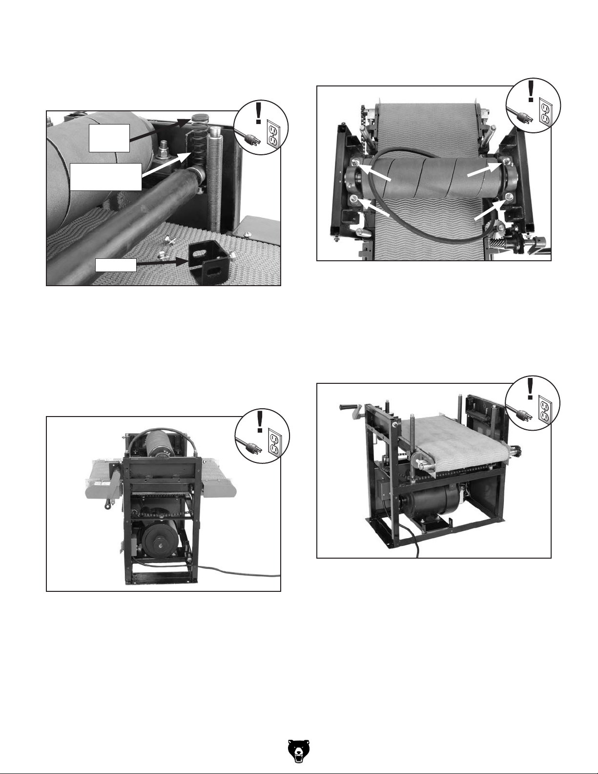
6. Remove the rear pressure roller (4 hex bolts
and 4 flat washers) along with the brackets, compression springs, and spring plates
shown in Figure 42.
Spring
Plate
Compression
Spring
NEW
Bracket
Figure 42. Rear pressure roller components.
7. Remove the rear panel.
8. Loosen the hex bolts securing the motor
bracket to the frame, raise the motor and
remove the V-belt from the motor pulley (see
Page 31 for help). The drum sander should
now look similar to Figure 43.
PHOTO
9. Remove the sanding drum (4 lock nuts and 4
flat washers) and V-belt (Figure 44).
NEW
PHOTO
Figure 44. Location to remove sanding drum
components.
10. Remove the front roller end guard covers (4
Phillip head screws) and the rear roller end
guard covers (4 Phillip head screws), and set
the covers aside. The drum sander should
now look similar to Figure 45.
Figure 43. Drum sander disassembled
to Step 8.
Model G0459/G0459P (Mfg. 7/11+)
Figure 45. Drum sander disassembled
to Step 10.
-39-
Page 42
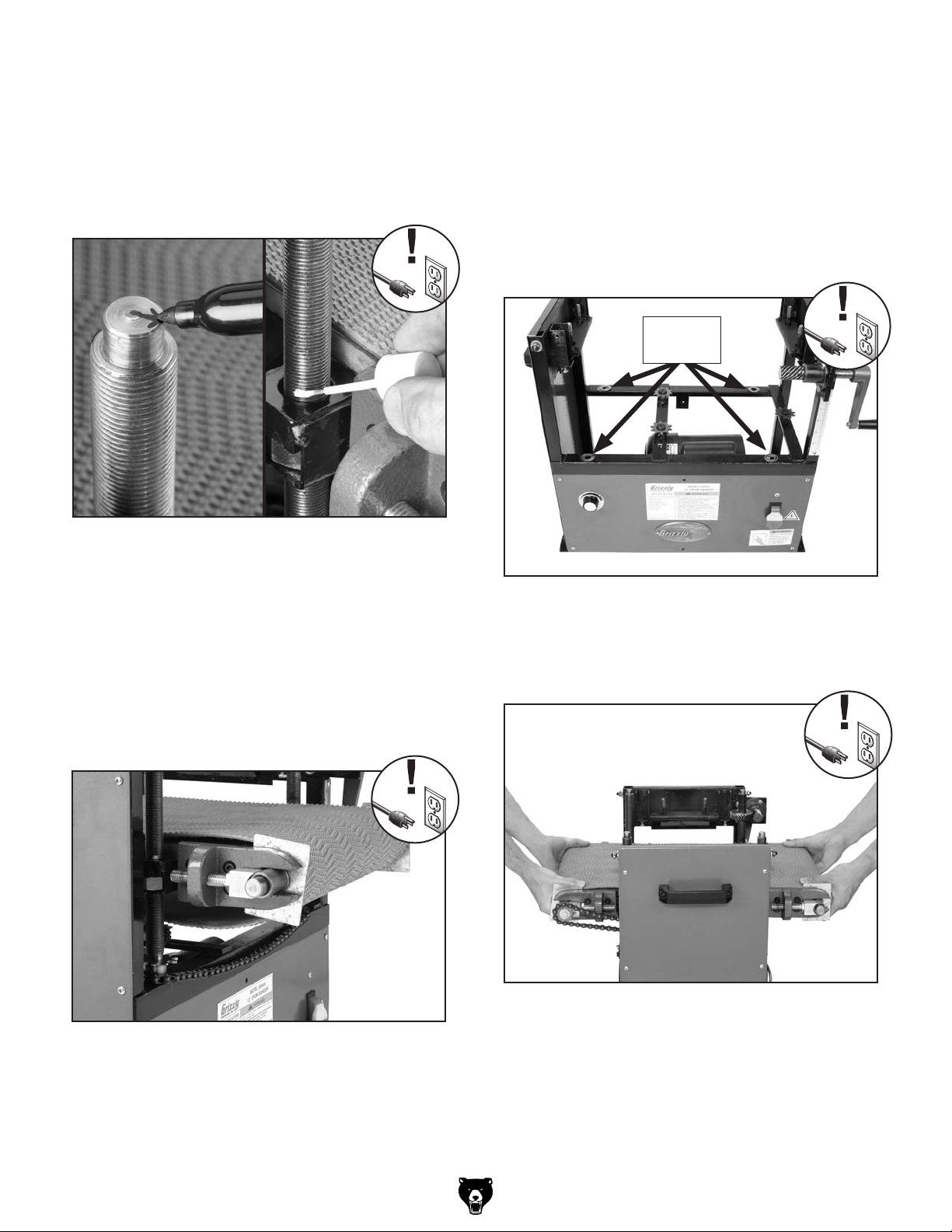
11. Mark the top of the table lift screws with
arrows (all pointing in same direction) and
mark the screws with liquid correction fluid
above the mounting bracket (Figure 46).
Later, when you reassemble the conveyor
table, you can use these marks to reset the
table height close to the current position.
NEW
PHOTO
Figure 46. Locations to mark table lift screws.
15. Disconnect the conveyor feed motor wires
from the circuit board.
16. Remove the scale pointer.
Before removing the table, note the number and
location of brass shims (Figure 48) under the
table lift screws. Knowing their correct position
will help you align the conveyor table during reassem bly.
Brass
Shims
12. Mark the chain and sprockets with correction
fluid.
13. Loosen the idler roller sprocket (Figure 39),
carefully pull the chain off of all the sprockets,
and remove it from the cabinet.
14. Loosen the conveyor belt at the front adjustments, as shown in Figure 47.
Figure 47. Conveyor belt loosened at the front
adjustments (only one shown).
Figure 48. Brass shims.
17. With the help of an assistant, carefully lift
the table off of the drum sander cabinet, as
shown in Figure 49.
Figure 49. Example of lifting the table off of the
drum sander cabinet with two people.
-40-
Model G0459/G0459P (Mfg. 7/11+)
Page 43
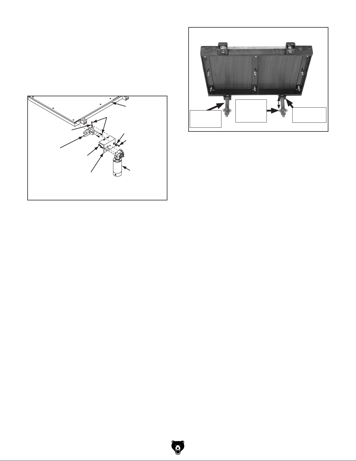
18. Lay the conveyor table on the edge of a
workbench so the conveyor motor can hang
freely.
19. Remove the conveyor motor (4 cap screws)
from the conveyor motor cover, and remove
the conveyor motor cover from left rear roller
bracket (3 cap screws and 3 flat washers).
Table
Cap Screws
Flat Washer
Left Rear
Roller Bracket
Cap
Screw
Conveyor
Motor
Cover
Flat Washer
Cap Screw
Conveyor
Motor
Figure 50. Removing conveyor motor and rear
roller bracket (not all components shown for
clarity).
20. Remove the rear left roller bracket (2 cap
screws).
21. Remove the rear roller.
22. Remove the front left roller bracket (2 cap
screws) and the front roller.
Front
Rear
Lift Screw
Right
Sprocket
Mounting
Bracket
Figure 51. Conveyor belt removed from table.
26. Measure the distance between the front right
table lift screw sprocket and the mounting
bracket. If necessary, rotate the rear shaft so
the sprocket-bracket distance is the same as
the front right table lift screw.
27. Install the new belt.
28. Re-install the front left and rear left table
lift screws to match the front right lift screw
height.
29. Reassemble the drum sander by reversing
the disassembly steps.
30. After reassembly, adjust the drums and pressure rollers to their proper settings. See Drum
Adjustments on Page 33 and Pressure
Roller Height on Page 35.
23. Remove the front right and rear roller brack-
ets (4 cap screws).
24. Place the right side of the conveyor on a flat
surface, then unthread and remove the front
and rear table lift screws.
25. Remove the belt. The table should look like
Figure 51.
Model G0459/G0459P (Mfg. 7/11+)
31. After you have re-installed the conveyor table,
make sure the four lower pressure roller
adjustment bolts are threaded the same distance into the roller mount brackets (Figure
34).
32. After re-installing the top cover and brace,
tighten the mounting bolts.
-41-
Page 44

33. Before re-installing the gear box cover, try
raising and lowering the conveyor table with
the crank handle. If the helical gears (see
Figure 52) are not engaged, the crank handle will only raise the table.
Changing Motor
Brushes
If this happens, loosen the crank handle
mounting bolts, and move the helical gear
around until the teeth mesh with the helical
crank handle gear, then secure the crank
handle.
Crank Handle
Helical Gear
Helical
Gear
Figure 52. Helical gear and crank handle helical
gear.
34. Re-install and secure the brace.
Tools Needed: Qty
Flat Head Screwdriver ....................................... 1
If the motor fails to develop full power or otherwise
appears to run sluggishly, the motor brushes may
need to be replaced.
To replace the motor brushes:
1. DISCONNECT POWER TO THE SANDER!
2. Remove each brush cover and remove the
brushes from the motor, as shown in Figure
53.
Motor Brush
Motor Brush
Cover
35. Try moving the conveyor table up and down.
36. Continue adjusting the helical gear and crank
handle helical gear until the crank handle
raises and lowers the conveyor table.
Figure 53. Motor brush components removed
(one of two brushes shown).
3. Insert the new carbon brushes into the holes
in the motor housing.
4. Re-install the brush covers.
-42-
Model G0459/G0459P (Mfg. 7/11+)
Page 45

These pages are current at the time of printing. However, in the spirit of improvement, we may make changes to the electrical systems of future machines. Compare the manufacture date of your machine to the one
number and manufacture date of your
machine before calling. This information can be found on the main machine label.
machine
SECTION 8: WIRING
stated in this manual, and study this section carefully.
If there are differences between your machine and what is shown in this section, call Technical Support at
(570) 546-9663 for assistance BEFORE making any changes to the wiring on your machine. An updated
wiring diagram may be available. Note: Please gather the serial
Wiring Safety Instructions
SHOCK HAZARD. Working on wiring that is connected to a power source is extremely dangerous.
Touching electrified parts will result in personal
injury including but not limited to severe burns,
electrocution, or death. Disconnect the power
from the machine before servicing electrical components!
MODIFICATIONS. Modifying the wiring beyond
what is shown in the diagram may lead to unpredictable results, including serious injury or fire.
This includes the installation of unapproved aftermarket parts.
WIRE CONNECTIONS. All connections must
be tight to prevent wires from loosening during
machine operation. Double-check all wires disconnected or connected during any wiring task to
ensure tight connections.
CIRCUIT REQUIREMENTS. You MUST follow
the requirements at the beginning of this manual when connecting your machine to a power
source.
WIRE/COMPONENT DAMAGE. Damaged wires
or components increase the risk of serious personal injury, fire, or machine damage. If you notice
that any wires or components are damaged while
performing a wiring task, replace those wires or
components.
MOTOR WIRING. The motor wiring shown in
these diagrams is current at the time of printing
but may not match your machine. If you find this
to be the case, use the wiring diagram inside the
motor junction box.
CAPACITORS/INVERTERS. Some capacitors
and power inverters store an electrical charge for
up to 10 minutes after being disconnected from
the power source. To reduce the risk of being
shocked, wait at least this long before working on
capacitors.
EXPERIENCING DIFFICULTIES. If you are experiencing difficulties understanding the information
included in this section, contact our Technical
Support at (570) 546-9663.
The photos and diagrams
included in this section are
best viewed in color. You
can view these pages in
color at www.grizzly.com.
Model G0459/G0459P (Mfg. 7/11+)
-43-
Page 46

Electrical Components
Figure 54. Feed motor.
Figure 55. Drum motor wiring.
Figure 57. Capacitor.
Figure 58. Variable speed control and circuit
board.
-44-
Figure 56. Switch box wiring.
READ ELECTRICAL SAFETY
ON PAGE 43!
Model G0459/G0459P (Mfg. 7/11+)
Page 47

ON
OFF
FEED
Ground
The motor wiring shown here is
current at the time of printing, but it
may not match your machine.
Always use the wiring diagram
inside the motor junction box.
Ground
MOTOR
(Figure 54)
Wiring Diagram
ON/OFF SWITCH
(Figure 56)
CIRCUIT
BOARD
(Figure 58)
VARIABLE
CONTROL
(Figure 58)
DC
SPEED
S Capacitor
300MFD
125VAC
DRUM MOTOR
(Figure 55)
2
6
3
5
THERMAL
CIRCUIT
BREAKER
1
(Figure 56)
Neutral
Hot
115 VAC
Ground
5-15 Plug
(As Recommended)
Model G0459/G0459P (Mfg. 7/11+)
wiring diagram
READ ELECTRICAL SAFETY
ON PAGE 43!
-45-
Page 48

225
211
44
12
29
14
20-2
20-7
20-3
12-1
20-6
20-4V2
12-2
104
20-5
135
136
SECTION 9: PARTS
Frame
29
10
13
29
14-1
8-7
22
130
120
8-4
8-3
8-5
8-2
6
8-7
7-1
7-2
44
45
40
34
24
100
57-2
111
59
122
57-1
33V2
103
99
134
117
118
108
101
17
134
133
29
17
18
135
107
11
29
19
223
22
24
5-1
22
24
134
110
109
5
4
20-1
28
55
54
212V3
119
112V2
32V3
209
209-1
119
113
115
29
20V2
138
114
3
54-1
57
8-7
8-1
6
8-7
29
2
46V2
56V2
137
121
8-6
7-1
7-2
9
1
30-1V2
30-2V2
8-7
8-1
6
8-7
6
8-7
30-3V2
40
34
30-4V2
15
8-7
8-1
135
136
16V2
30-5
134
132
31-1
29
29
224
29
31V2
4
5
5-1
-46-
Model G0459/G0459P (Mfg. 7/11+)
Page 49

Frame Parts List
REF PART # DESCRIPTION REF PART # DESCRIPTION
1 P0459001 FRAME 32V3 P0459P032V3 FRONT PANEL V3.01.11
2 PN02 HEX NUT 5/16-18 33V2 P0459033V2 PUSH BUTTON SWITCH V2.03.09
3 PW07 FLAT WASHER 5/16 34 PN02 HEX NUT 5/16-18
4 P0459004 SIDE PANEL 40 PW07 FLAT WASHER 5/16
4 P0459P004 SIDE PANEL 44 PN05 HEX NUT 1/4-20
5 P0459005 HANDLE 45 PB05 HEX BOLT 1/4-20 X 3/4
5-1 PCAP09 CAP SCREW 5/16-18 X 5/8 46V2 P0459046V2 PC BRD CONSOLE UNIT V2.03.09
6 P0459006 SPROCKET V1 54 P0459054 VARIABLE SPEED CTL KNOB
7-1 P0459007-1 SPROCKET SHAFT 54-1 P0459054-1 POTENTIOMETER
7-2 P0459007-2 SPROCKET 55 P0459055 SPEED INDICATOR LABEL
8-1 P0459008-1 TABLE LEAD SCREW (1) 56V2 P0459056V2 SWITCH BOX V2.03.09
8-2 P0459008-2 TABLE LEAD SCREW (2) 56V2 P0459P056V2 SWITCH BOX V2.03.09
8-3 P0459008-3 BUSHING 57 PFS17 FLANGE SCREW 10-24 X 1/2
8-4 P0459008-4 WORM GEAR 25-TEETH 57-1 PN07 HEX NUT #10-24
8-5 PK06M KEY 5 X 5 X 10 57-2 PS06 PHLP HD SCR 10-24 X 3/8
8-6 P0459008-6 BUSHING 59 PTLW02M EXT TOOTH WASHER 5MM
8-7 PW01 FLAT WASHER 1/2 99 PAW03M HEX WRENCH 3MM
9 P0459009 ELEVATION CHAIN 100 P0459100 DUST SCOOP
10 P0459010 FRONT BRACE 100 P0459P100 DUST SCOOP
10 P0459P010 FRONT BRACE 101 P0459101 WORM GEAR SHAFT BRACKET
11 P0459011 DEPTH SCALE 103 P0459103 SHAFT MOUNT
12 P0459012 RIGHT SUPPORT ARM 104 P0459104 WORM GEAR
12-1 PS41 PHLP HD SCR 6-32 X 1/4 107 P0459107 BUSHING
12-2 PN12 HEX NUT 6-32 108 PB19 HEX BOLT 1/4-20 X 1/2
13 G2977 UNIVERSAL DUST PORT 2-1/2" 109 P0459109 COLLAR
14 P0459014 TOP COVER 110 P0459110 WORM GEAR MOUNT WASHER
14 P0459P014 TOP COVER 111 P0459111 WIRES
14-1 P0459014-1 HINGE 112V2 P0459112V2 GEAR COVER V2.07.11
15 P0459015 REAR BRACE 112V2 P0459P112V2 GEAR COVER V2.07.11
15 P0459P015 REAR BRACE 113 P0459113 CRANK HANDLE
16V2 P0459016V2 REAR PANEL V2.03.09 113 P0459P113 CRANK HANDLE
16V2 P0459P016V2 REAR PANEL V2.03.09 114 P0459114 HANDLE
17 PSS03 SET SCREW 1/4-20 X 3/8 115 PN08 HEX NUT 3/8-16
18 P0459018 MOTOR PULLEY 117 PW07 FLAT WASHER 5/16
19 PK110 KEY 1/4 X 1/4 X 1 118 PB03 HEX BOLT 5/16-18 X 1
20V2 P0459020V2 MOTOR 1.5HP 110V 1PH V2.03.09 119 PSS11 SET SCREW 1/4-20 X 1/4
20-1 P0459020-1 MOTOR BRACKET 120 P0459120 OL RELAY YS 20A
20-2 P0459020-2 S CAP 300M 125V 1-1/2 X 3-1/8 121 P0459121 HEX NUT SIZE M11-1
20-3 P0459020-3 CAPACITOR COVER 122 P0459122 JUMPER
20-4V2 P0459020-4V2 JUNCTION BOX V2.03.09 130 P0459130 PC BOARD COVER
20-5 P0459020-5 FAN COVER 132 P0459132 FRONT ELEVATION CHAIN GUARD
20-6 P0459020-6 MOTOR FAN 133 P0459133 REAR ELEVATION CHAIN GUARD
20-7 P0459020-7 CENTRIFUGAL SWITCH 134 PS06 PHLP HD SCR 10-24 X 3/8
22 PB07 HEX BOLT 5/16-18 X 3/4 135 PW03 FLAT WASHER #10
24 PW07 FLAT WASHER 5/16 136 PN07 HEX NUT #10-24
28 P0459028 FLANGE SCREW M3-.6 X 16 137 P0459137 PADLOCK STORAGE HOOK
29 PHTEK7 TAP SCREW #8 X 3/8 138 P0459138 SWITCH PADLOCK
30-1V2 P0459030-1V2 POWER CORD V2.03.09 209 G9987 GRIZZLY NAMEPLATE-MINI
30-2V2 P0459030-2V2 MOTOR CORD V2.03.09 209-1 PHTEK24 TAP SCREW #5 X 3/8
30-3V2 P0459030-3V2 VS POWER CORD V2.03.09 211 P0459211 COVER LOCK KNOB
30-4V2 P0459030-4V2 DC MOTOR CORD V2.03.09 212V3 P0459212V3 MACHINE ID LABEL CSA V3.07.11
30-5 P0459030-5 CONTROL WIRE 212V3 P0459P212V3 MACHINE ID LABEL CSA V3.01.11
31V2 P0459031V2 STRAIN RELIEF MGB16 V2.07.11 223 PLABEL-75 POLAR BEAR LOGO 2-1/2 X 9-1/2
31-1 P0459031-1 STRAIN RELIEF 3/4" 224 PPAINT-24 POLAR BEAR WHITE TOUCH-UP PAINT
32V3 P0459032V3 FRONT PANEL V3.01.11 225 P0459P225 MODEL NUMBER LABEL
Model G0459/G0459P (Mfg. 7/11+)
-47-
Page 50

Drum
86
85
81
27
74
86
85
82
73
88
70
25
89-1
89
17
94
23
42
90
26
89
89-1
88
74
73
71
70
25
89-1
89
23
89
89-1
90
26
88
74
73
86
88
98
92-1
REF PART # DESCRIPTION REF PART # DESCRIPTION
17 PSS03 SET SCREW 1/4-20 X 3/8 82 PSS51 SET SCREW 5/16-24 X 1/2
23 PB02 HEX BOLT 1/4-20 X 5/8 85 PW02 FLAT WASHER 3/8
25 PN05 HEX NUT 1/4-20 86 PLN01 LOCK NUT 3/8-16
26 P0459026 SPRING PLATE 88 P0459088 COMP SPRING 24-20-8MM 63L
27 P0459027 ADJUST PLATE 89 PB51 HEX BOLT 1/4-20 X 3/8
42 PK34M KEY 5 X 5 X 20 89-1 PW06 FLAT WASHER 1/4
70 P0459070 PRESSURE ROLLER 90 P0459090 BRACKET
71 P0459071 SANDING DRUM 92 P0459092 HOOK & LOOP SANDBELT
73 PR08M EXT RETAINING RING 19MM 92-1 P0459092-1 HOOK & LOOP DRUM COVER
74 P1066062 BUSHING 94 P0459094 DRUM PULLEY
81 P1066081A PILLOW BLOCK BEARING 98 PVA36 V-BELT 4L360
92
74
73
86
85
85
81
82
27
-48-
Model G0459/G0459P (Mfg. 7/11+)
Page 51

57
50-1
51-3V2
125
127
64
65V3
50-2
102
35
57
36
58
64
35
17
79
25
125
80
124
77
51-2V4
123
Conveyor
52
66
74
64
61
51-1V2
126
60
35
78
76
76
127
83
38V2
78
63
65-1
60
51V2
58
39V4
69
61
64
74
57
50-1
39V4-1
39V4-2
39V4-3
39V4-4
39V4-6
39V4-5
39V4-5
Model G0459/G0459P (Mfg. 7/11+)
39V4-7
39V4-8
39V4-9
39V4-14
39V4-11
39V4-7
39V4-13
39V4-10
39V4-15
39V4-12
39V4-16
39V4-14
39V4-13
-49-
Page 52

Conveyor Parts List
REF PART # DESCRIPTION
REF PART # DESCRIPTION REF PART # DESCRIPTION
17 PSS03 SET SCREW 1/4-20 X 3/8 51-2V4 P0459051-2V4 LEFT REAR ROLLER BRACKET V4.01.11
25 PN05 HEX NUT 1/4-20 51-3V2 P0459051-3V2 RIGHT REAR ROLLER BRACKET V2.07.11
35 PN03 HEX NUT 3/4-16 52 PFH12 FLAT HD SCR 1/4-20 X 1
36 P0459036 TABLE FRAME 57 PFS17 FLANGE SCREW 10-24 X 1/2
38V2 P0459038V2 CONVEYOR MOTOR BRACKET V2.03.09 58 PCAP01 CAP SCREW 1/4-20 X 5/8
39V4 P0459039V4 DC FEED MOTOR 105W V4.11.09 60 P0459060 ROLLER BRACKET BOLT
39V4-1 PS56M PHLP HD SCR M4-.7 X 16 61 P0459061 BUSHING SUPPORT
39V4-2 PLW02M LOCK WASHER 4MM 63 P0459063 SET SCREW 1/4-20 X 3/16
39V4-3 P0459039V4-3 END CASE V4.11.09 64 P0459064 PLATE
39V4-4 P0459039V4-4 DRIVE GEAR V4.11.09 65V3 P0459065V3 DRIVE ROLLER V3.09.09
39V4-5 P6003ZZ BALL BEARING 6003ZZ 65-1 P0459065-1 IDLER ROLLER
39V4-6 P0459039V4-6 MAIN CASE V4.11.09 66 P0459066 TABLE
39V4-7 P6000ZZ BALL BEARING 6000ZZ 69 P0459069 CONVEYOR BELT 1220 X 312MM
39V4-8 PR06M EXT RETAINING RING 16MM 74 P1066062 BUSHING
39V4-9 P0459039V4-9 ARMATURE V4.11.09 76 PW06 FLAT WASHER 1/4
39V4-10 P0459039V4-10 FEED MOTOR POWER CORD V4.11.09 77 P0459077 SCALE POINTER
39V4-11 P0459039V4-11 STATOR HOUSING V4.11.09 78 PCAP01 CAP SCREW 1/4-20 X 5/8
39V4-12 P0459039V4-12 MIDDLE CAP V4.11.09 79 PS06 PHLP HD SCR 10-24 X 3/8
39V4-13 P0459039V4-13 CARBON BRUSH ASSEMBLY V4.11.09 80 PW03 FLAT WASHER #10
39V4-14 P0459039V4-14 PLASTIC LOCK CAP V4.11.09 83 PCAP28M CAP SCREW M6-1 X 15
39V4-15 P0459039V4-15 END CAP V4.11.09 102 PLN02 LOCK NUT 1/4-20
39V4-16 PS19M PHLP HD SCR M5-.8 X 6 123 P0459123 COLLAR
50-1 P0459050-1 LEFT ROLLER END GUARD COVER 124 PK23M KEY 5 X 5 X 25
50-2 P0459050-2 RIGHT ROLLER END GUARD COVER 125 P6003-2RS BALL BEARING 6003-2RS
51V2 P0459051V2 LEFT ROLLER BRACKET V2.07.11 126 PSS11 SET SCREW 1/4-20 X 1/4
51-1V2 P0459051-1V2 RIGHT FRONT ROLLER BRACKET V2.07.11 127 PCAP06 CAP SCREW 1/4-20 X 1
Label Placement
214
REF PART # DESCRIPTION
55 P0459055 SPEED INDICATOR LABEL
209 G9987 GRIZZLY NAMEPLATE-MINI
212V3 P0459212V3 MACHINE ID LABEL CSA V3.07.11
212V3 P0459P212V3 MACHINE ID LABEL CSA V3.07.11
213 P0459213 RESPIRATOR-GLASSES LABEL
214 PLABEL-22 HAND PINCH IN BELT LABEL
215 P0459215 KICKBACK HAZARD LABEL
216 P0459216 DISCONNECT POWER LABEL
217 PLABEL-14 ELECTRICITY LABEL
218 PLABEL-12B READY MANUAL HZ LABEL
221 PPAINT-1 GRIZZLY GREEN TOUCH-UP PAINT
222 PPAINT-7 BLACK TOUCH-UP PAINT
222
213
55
218
212V2
209
Safety labels warn about machine hazards and ways to prevent injury. The owner of this machine
MUST maintain the original location and readability of the labels on the machine. If any label is
removed or becomes unreadable, REPLACE that label before using the machine again. Contact
Grizzly at (800) 523-4777 or www.grizzly.com to order new labels.
215
216
217
221
-50-
Model G0459/G0459P (Mfg. 7/11+)
Page 53

WARRANTY CARD
Name _____________________________________________________________________________
Street _____________________________________________________________________________
City _______________________ State _________________________ Zip _____________________
Phone # ____________________ Email _________________________________________________
Model # ____________________ Order # _______________________ Serial # __________________
The following information is given on a voluntary basis. It will be used for marketing purposes to help us develop
better products and services. Of course, all information is strictly confidential.
1. How did you learn about us?
____ Advertisement ____ Friend ____ Catalog
____ Card Deck ____ Website ____ Other:
2. Which of the following magazines do you subscribe to?
____ Cabinetmaker & FDM
____ Family Handyman
____ Hand Loader
____ Handy
____ Home Shop Machinist
____ Journal of Light Cont.
____ Live Steam
____ Model Airplane News
____ Old House Journal
____ Popular Mechanics
3. What is your annual household income?
____ $20,000-$29,000 ____$30,000-$39,000 ____ $40,000-$49,000
____ $50,000-$59,000 ____$60,000-$69,000 ____ $70,000+
CUT ALONG DOTTED LINE
4. What is your age group?
____ 20-29 ____ 30-39 ____ 40-49
____ 50-59 ____ 60-69 ____ 70+
5. How long have you been a woodworker/metalworker?
____ 0-2 Years ____ 2-8 Years ____ 8-20 Years ____ 20+ Years
6. How many of your machines or tools are Grizzly?
____ 0-2 ____ 3-5 ____ 6-9 ____10+
____ Popular Science
____ Popular Woodworking
____ Precision Shooter
____ Projects in Metal
____ RC Modeler
____ Rie
____ Shop Notes
____ Shotgun News
____ Today’s Homeowner
____ Wood
____ Wooden Boat
____ Woodshop News
____ Woodsmith
____ Woodwork
____ Woodworker West
____ Woodworker’s Journal
____ Other:
7. Do you think your machine represents a good value? _____Yes _____No
8. Would you recommend Grizzly Industrial to a friend? _____Yes _____No
9. Would you allow us to use your name as a reference for Grizzly customers in your area?
Note: We never use names more than 3 times. _____Yes _____No
10. Comments: _____________________________________________________________________
_________________________________________________________________________________
_________________________________________________________________________________
_________________________________________________________________________________
Page 54

FOLD ALONG DOTTED LINE
FOLD ALONG DOTTED LINE
Place
Stamp
Here
GRIZZLY INDUSTRIAL, INC.
P.O. BOX 2069
BELLINGHAM, WA 98227-2069
Send a Grizzly Catalog to a friend:
Name_______________________________
Street_______________________________
City______________State______Zip______
TAPE ALONG EDGES--PLEASE DO NOT STAPLE
Page 55

WARRANTY AND RETURNS
We shall in no event be liable for death, injuries to persons or property or for incidental, contingent, special,
WARRANTY AND RETURNS
Grizzly Industrial, Inc. warrants every product it sells for a period of 1 year to the original purchaser from
the date of purchase. This warranty does not apply to defects due directly or indirectly to misuse, abuse,
negligence, accidents, repairs or alterations or lack of maintenance. This is Grizzly’s sole written warranty
and any and all warranties that may be implied by law, including any merchantability or fitness, for any particular purpose, are hereby limited to the duration of this written warranty. We do not warrant or represent
that the merchandise complies with the provisions of any law or acts unless the manufacturer so warrants.
In no event shall Grizzly’s liability under this warranty exceed the purchase price paid for the product and
any legal actions brought against Grizzly shall be tried in the State of Washington, County of Whatcom.
or consequential damages arising from the use of our products.
To take advantage of this warranty, contact us by mail or phone and give us all the details. We will then
issue you a “Return Number,’’ which must be clearly posted on the outside as well as the inside of the
carton. We will not accept any item back without this number. Proof of purchase must accompany the
merchandise.
The manufacturers reserve the right to change specifications at any time because they constantly strive to
achieve better quality equipment. We make every effort to ensure that our products meet high quality and
durability standards and we hope you never need to use this warranty.
Please feel free to write or call us if you have any questions about the machine or the manual.
Thank you again for your business and continued support. We hope to serve you again soon.
Page 56

Buy Direct and Save with Grizzly®– Trusted, Proven and a Great Value!
~Since 1983~
Visit Our Website Today For
Current Specials!
ORDER
24 HOURS A DAY!
1-800-523-4777
 Loading...