

Page 1

MODEL G0458
18" OPEN-END DRUM SANDER
OWNER'S MANUAL
COPYRIGHT © AUGUST, 2005 BY GRIZZLY INDUSTRIAL, INC. REVISED JUNE, 2011 (TS)
WARNING: NO PORTION OF THIS MANUAL MAY BE REPRODUCED IN ANY SHAPE
OR FORM WITHOUT THE WRITTEN APPROVAL OF GRIZZLY INDUSTRIAL, INC.
(FOR MODELS MANUFACTURED SINCE 5/11) #TRCREWPCBL7423 PRINTED IN CHINA
Page 2

This manual provides critical safety instructions on the proper setup,
operation, maintenance, and service of this machine/tool. Save this
document, refer to it often, and use it to instruct other operators.
Failure to read, understand and follow the instructions in this manual
may result in fire or serious personal injury—including amputation,
electrocution, or death.
The owner of this machine/tool is solely responsible for its safe use.
This responsibility includes but is not limited to proper installation in
a safe environment, personnel training and usage authorization,
proper inspection and maintenance, manual availability and comprehension, application of safety devices, cutting/sanding/grinding tool
integrity, and the usage of personal protective equipment.
The manufacturer will not be held liable for injury or property damage
from negligence, improper training, machine modifications or misuse.
Some dust created by power sanding, sawing, grinding, drilling, and
other construction activities contains chemicals known to the State
of California to cause cancer, birth defects or other reproductive
harm. Some examples of these chemicals are:
• Lead from lead-based paints.
• Crystalline silica from bricks, cement and other masonry products.
• Arsenic and chromium from chemically-treated lumber.
Your risk from these exposures varies, depending on how often you
do this type of work. To reduce your exposure to these chemicals:
Work in a well ventilated area, and work with approved safety equipment, such as those dust masks that are specially designed to filter
out microscopic particles.
Page 3

Table of Contents
INTRODUCTION ............................................... 2
Manual Accuracy ........................................... 2
Contact Info.................................................... 2
Identification ................................................... 3
Machine Data Sheet ...................................... 4
SECTION 1: SAFETY ....................................... 6
Safety Instructions for Machinery .................. 6
Additional Safety for Drum Sanders .............. 8
SECTION 2: POWER SUPPLY ........................ 9
SECTION 3: SETUP ....................................... 11
Needed for Setup ......................................... 11
Unpacking .................................................... 11
Inventory ...................................................... 12
Site Considerations ...................................... 13
Assembly ..................................................... 14
Dust Collection ............................................. 17
Test Run ...................................................... 18
Recommended Adjustments ........................ 18
SECTION 4: OPERATIONS ........................... 19
Depth of Cut ................................................. 19
Variable Speed ............................................ 20
Sanding ........................................................ 20
Sanding Tips ................................................ 21
Choosing Sandpaper ................................... 21
Paper Replacement ..................................... 22
SECTION 5: ACCESSORIES ......................... 24
SECTION 6: MAINTENANCE ......................... 25
Schedule ...................................................... 25
Cleaning ....................................................... 25
Lubrication ................................................... 25
Sanding Belts ............................................... 26
V-Belt Tensioning......................................... 27
SECTION 7: SERVICE ................................... 28
Troubleshooting ........................................... 28
Replacing V-Belts ........................................ 30
Pulley Alignment .......................................... 31
Feed Belt Tracking ....................................... 31
Feed Belt Tension ........................................ 32
Feed Belt Replacement ............................... 33
Gauge Blocks............................................... 34
Table Adjustments ....................................... 34
Pressure Plate Adjustments ........................ 35
SECTION 8: WIRING ...................................... 37
Wiring Safety Instructions ............................ 37
Wiring Diagram ............................................ 38
G0458 Parts Breakdown .............................. 39
WARRANTY & RETURNS ............................. 45
Page 4

INTRODUCTION
We are proud to offer this manual with your new
machine! We've made every effort to be exact
with the instructions, specifications, drawings,
and photographs of the machine we used when
writing this manual. However, sometimes we still
make
Also, owing to our policy of continuous improvement, your machine may not exactly match the
manual. If you find this to be the case, and the dif-
ference between the manual and machine leaves
you in doubt,
manual update or call technical support for help.
Before calling, find the manufacture date of your
machine by looking at the date stamped into the
machine ID label (see below). This will help us
determine if the manual version you received
matches the manufacture date of your machine.
For your convenience, we
-
uals and
on our website
at
model
of
as soon as they are complete.
We stand behind our machines. If you have
any questions or need help, use the information
below to contact us. Before contacting, please get
the serial number and manufacture date of your
machine. This will help us help you faster.
We want your feedback on this manual. What did
you like about it? Where could it be improved?
Please take a few minutes to give us feedback.
Email: manuals@grizzly.com
Manual Accuracy
an occasional mistake.
www.grizzly.com. Any updates to your
machine will be reflected in these documents
check our website for the latest
Manufacture Date
of Your Machine
post all available man
manual updates for free
Contact Info
Grizzly Technical Support
1203 Lycoming Mall Circle
Muncy, PA 17756
Phone: (570) 546-9663
Email: techsupport@grizzly.com
Grizzly Documentation Manager
P.O. Box 2069
Bellingham, WA 98227-2069
-2-
Model G0458 (Mfg. Since 5/11)
Page 5

Identification
E
A
B
F
C
D
Figure 1. Main controls/components of the sander.
A. Circuit Breaker
B. ON/OFF Switch w/Lockout Key
C. Feed Speed Scale
D. Variable Speed Feed Rate Knob
E. Return Roller
F. Table Height Adjustment Handwheel
G. Feed Belt
H. Dust Port
G
H
Model G0458 (Mfg. Since 5/11)
-3-
Page 6

Machine Data Sheet
MACHINE DATA
SHEET
Customer Service #: (570) 546-9663 · To Order Call: (800) 523-4777 · Fax #: (800) 438-5901
MODEL G0458 18" 1-1/2 HP SINGLE-PHASE OPEN END
DRUM SANDER
Product Dimensions:
Weight.............................................................................................................................................................. 198 lbs.
Width (side-to-side) x Depth (front-to-back) x Height........................................................................... 35 x 24 x 50 in.
Footprint (Length x Width)............................................................................................................................ 35 x 17 in.
Shipping Dimensions:
Type.......................................................................................................................................................... Wood Crate
Content........................................................................................................................................................... Machine
Weight.............................................................................................................................................................. 328 lbs.
Length x Width x Height....................................................................................................................... 25 x 33 x 33 in.
Must Ship Upright................................................................................................................................................... Yes
Electrical:
Power Requirement........................................................................................................... 110V, Single-Phase, 60 Hz
Prewired Voltage.................................................................................................................................................. 110V
Full-Load Current Rating........................................................................................................................................ 15A
Minimum Circuit Size.............................................................................................................................................. 20A
Connection Type....................................................................................................................................... Cord & Plug
Power Cord Included.............................................................................................................................................. Yes
Power Cord Length.......................................................................................................................................... 6-1/2 ft.
Power Cord Gauge......................................................................................................................................... 14 AWG
Recommended Power Cord................................................................................................................................... N/A
Plug Included.......................................................................................................................................................... Yes
Included Plug Type................................................................................................................................................ 5-15
Recommended Plug Type...................................................................................................................................... N/A
Switch Type.................................................................................................. Paddle Safety Switch w/Removable Key
Voltage Conversion Kit........................................................................................................................................... N/A
Inverter Type.......................................................................................................................................................... N/A
Inverter Size........................................................................................................................................................... N/A
Recommended Phase Converter........................................................................................................................... N/A
-4-
Motors:
Main
Type................................................................................................................. TEFC Capacitor-Start Induction
Horsepower............................................................................................................................................. 1.5 HP
Phase............................................................................................................................................ Single-Phase
Amps............................................................................................................................................................ 15A
Speed................................................................................................................................................ 1725 RPM
Power Transfer ............................................................................................................................... V-Belt Drive
Bearings..................................................................................................... Shielded & Permanently Lubricated
Model G0458 (Mfg. Since 5/11)
Page 7

Main Specifications:
Operation Information
No Of Sanding Heads....................................................................................................................................... 1
Maximum Board Width.............................................................................................................................. 36 in.
Minimum Board Width................................................................................................................................. 1 in.
Maximum Board Thickness................................................................................................................... 4-1/2 in.
Minimum Board Thickness....................................................................................................................... 1/8 in.
Minimum Board Length................................................................................................................................ 6 in.
Sandpaper Speed.............................................................................................................................. 4000 FPM
Conveyor Feed Rate........................................................................................................................ 2 – 12 FPM
Sandpaper Length..................................................................................................................................... 82 in.
Sandpaper Width......................................................................................................................................... 3 in.
Drum Information
Infeed Sanding Drum Type................................................................................................................. Aluminum
Infeed Sanding Drum Size........................................................................................................................... 4 in.
Construction
Conveyor Belt................................................................................................................................... Sandpaper
Body........................................................................................................................................................... Steel
Base........................................................................................................................................................... Steel
Paint........................................................................................................................................... Powder Coated
Other Related Information
Floor To Table Height......................................................................................................................... 35 - 40 in.
Sanding Belt Tension.................................................................................................................. Spring Loaded
Conveyor Belt Length.......................................................................................................................... 44-1/2 in.
Conveyor Belt Width.................................................................................................................................. 18 in.
Belt Roller Size...................................................................................................................................... 1-1/2 in.
No Of Dust Ports.............................................................................................................................................. 1
Dust Port Size........................................................................................................................................ 2-1/2 in.
Other Specifications:
Country Of Origin ............................................................................................................................................... China
Warranty ........................................................................................................................................................... 1 Year
Approximate Assembly & Setup Time ...................................................................................................... 1-1/2 Hours
Serial Number Location .................................................................................................................................. ID Label
ISO 9001 Factory .................................................................................................................................................... No
CSA Certified .......................................................................................................................................................... No
Features:
Spring-Loaded Sanding Belt Tension
Sandpaper Conveyor Belt
2-1/2" Dust Port
Variable Speed Conveyor
V-Belt Motor Drive
4" Aluminum Sanding Drum
Green and Putty Powder Coated Paint
Stand Alone Dust Collection with Dust Bag
Stationary Drum Headstock
Board Return Roller
Safety Switch
Easy Access for Sandpaper Changes
Model G0458 (Mfg. Since 5/11)
-5-
Page 8

SECTION 1: SAFETY
For Your Own Safety, Read Instruction
Manual Before Operating This Machine
The purpose of safety symbols is to attract your attention to possible hazardous conditions.
This manual uses a series of symbols and signal words intended to convey the level of importance of the safety messages. The progression of symbols is described below. Remember that
safety messages by themselves do not eliminate danger and are not a substitute for proper
accident prevention measures. Always use common sense and good judgment.
Indicates an imminently hazardous situation which, if not avoided,
WILL result in death or serious injury.
Indicates a potentially hazardous situation which, if not avoided,
COULD result in death or serious injury.
Indicates a potentially hazardous situation which, if not avoided,
MAY result in minor or moderate injury. It may also be used to alert
against unsafe practices.
This symbol is used to alert the user to useful information about
NOTICE
OWNER’S MANUAL. Read and understand this
owner’s manual BEFORE using machine.
TRAINED OPERATORS ONLY. Untrained operators have a higher risk of being hurt or killed.
Only allow trained/supervised people to use this
machine. When machine is not being used, disconnect power, remove switch keys, or lock-out
machine to prevent unauthorized use—especially
around children. Make workshop kid proof!
DANGEROUS ENVIRONMENTS. Do not use
machinery in areas that are wet, cluttered, or have
poor lighting. Operating machinery in these areas
greatly increases the risk of accidents and injury.
MENTAL ALERTNESS REQUIRED. Full mental
alertness is required for safe operation of machinery. Never operate under the influence of drugs or
alcohol, when tired, or when distracted.
proper operation of the machine.
ELECTRICAL EQUIPMENT INJURY RISKS. You
can be shocked, burned, or killed by touching live
electrical components or improperly grounded
machinery. To reduce this risk, only allow qualified
service personnel to do electrical installation or
repair work, and always disconnect power before
accessing or exposing electrical equipment.
DISCONNECT POWER FIRST.
nect machine from power supply BEFORE making
adjustments, changing tooling, or servicing machine.
This prevents an injury risk from unintended startup
or contact with live electrical components.
EYE PROTECTION. Always wear ANSI-approved
safety glasses or a face shield when operating or
observing machinery to reduce the risk of eye
injury or blindness from flying particles. Everyday
eyeglasses are not approved safety glasses.
Always discon-
-6-
Model G0458 (Mfg. Since 5/11)
Page 9

WEARING PROPER APPAREL. Do not wear
clothing, apparel or jewelry that can become
entangled in moving parts. Always tie back or
coverlong hair. Wearnon-slip footwear to avoid
accidentalslips,whichcouldcause lossofworkpiececontrol.
hAzARdOus dusT. Dust created while using
machinery may cause cancer, birth defects, or
long-term respiratory damage. Be aware of dust
hazardsassociatedwitheachworkpiecematerial,
andalwayswearaNIOSH-approvedrespiratorto
reduceyourrisk.
hEARING PROTECTION. Always wear hearing protection when operating or observing loud
machinery. Extended exposure to this noise
withouthearing protection can cause permanent
hearingloss.
REMOVE AdJusTING TOOLs. Tools left on
machinery can become dangerous projectiles
uponstartup.Neverleavechuckkeys,wrenches,
or any other tools on machine. Always verify
removalbeforestarting!
INTENdEd usAGE. Only use machine for its
intendedpurposeand nevermake modifications
not approved by Grizzly. Modifying machine or
using it differently than intended may result in
malfunctionormechanicalfailurethatcanleadto
seriouspersonalinjuryordeath!
AWKWARd POsITIONs. Keep proper footing
andbalanceatalltimeswhenoperatingmachine.
Donotoverreach!Avoidawkwardhandpositions
that make workpiece control difficult or increase
the
riskofaccidentalinjury.
ChILdREN & BYsTANdERs. Keepchildrenand
bystandersatasafedistancefromtheworkarea.
Stopusingmachineiftheybecomeadistraction.
FORCING MAChINERY.Donot forcemachine.
Itwill do the job safer and better at the rate for
whichitwasdesigned.
NEVER sTANd ON MAChINE. Serious injury
may occur if machine is tipped or if the cutting
toolisunintentionallycontacted.
sTABLE MAChINE. Unexpectedmovementduring operation greatly increases risk of injury or
lossofcontrol.Beforestarting,verify machineis
stableandmobilebase(ifused)islocked.
usE RECOMMENdEd ACCEssORIEs.Consult
thisowner’smanualorthemanufacturerforrecommended accessories. Using improper accessorieswillincreasetheriskofseriousinjury.
uNATTENdEd OPERATION. To reduce the
risk of accidental injury, turn machine off and
ensure all moving parts completely stop before
walking away. Never leave machine running
whileunattended.
MAINTAIN WITh CARE.Followallmaintenance
instructions and lubrication schedules to keep
machine in good working condition. A machine
that is
leadingtoseriouspersonalinjuryordeath.
ChECK dAMAGEd PARTs. Regularly inspect
machine for any condition that may affect safe
operation.Immediatelyrepairorreplacedamaged
ormis-adjustedpartsbeforeoperatingmachine.
MAINTAIN POWER CORds. When disconnecting cord-connected machines from power, grab
andpulltheplug—NOTthecord.Pullingthecord
may damage the wires inside. Do not handle
cord/plugwithwethands.Avoidcorddamage by
keepingitawayfromheatedsurfaces,hightraffic
areas,harshchemicals,andwet/damplocations.
improperly maintained could malfunction,
GuARds & COVERs.Guardsandcoversreduce
accidental contact with moving parts or flying
debris. Make sure they are properly installed,
undamaged,andworkingcorrectly.
Model G0458 (Mfg. Since 5/11)
EXPERIENCING dIFFICuLT IEs. If at any time
youexperiencedifficulties performingtheintendedoperation,stopusingthemachine!Contactour
TechnicalSupportat(570)546-9663.
-7-
Page 10

Additional Safety for Drum Sanders
FEEDING STOCK. Do not allow anyone to stand
in the path of the workpiece at the outfeed end
when feeding your stock. Never sand more than
one piece of stock at a time. Do not jam the
workpiece into the machine during operation.
Firmly grasp the workpiece in both hands and
ease it into the machine using light pressure.
MINIMUM STOCK DIMENSIONS. Do not sand
any stock thinner than
shorter than 6". Do not sand thin stock by using a
“dummy” board under your workpiece.
CLOTHING. Do not wear loose clothing while
operating this machine. Roll up or button sleeves
at the cuff.
HAND PROTECTION. Do not place hands near,
or in contact with, sanding drums during operation. Do not allow fingers to get pinched between
board and conveyor belt during operation. This
may pull the operator’s hand into the machine and
cause serious injury!
1
⁄8", narrower than 1⁄8", or
DUST COLLECTION SYSTEM. Never operate
the sander without an adequate dust collection
system in place and running.
UNAT TEND ED OPER ATION . Never leave the
machine running unattended.
REPLACING SANDING PAPER. Replace sanding paper when it becomes worn.
EXPERIENCING DIFFICULTIES. Any problem,
with the exception of conveyor belt tracking that is
concerned with any moving parts or accessories,
must be investigated and corrected with the power
disconnected, and after all moving parts have
come to a complete stop.
MAINTENANCE AND ADJUSTMENTS. Never
attempt to adjust conveyor belt tracking when the
sanding drums are engaged. Perform machine
inspections and maintenance service promptly
when called for. Disconnect power before performing maintenance or adjustments on the sander.
INSPECTING WORKPIECES. Always inspect
workpiece for nails, staples, knots, and other
imperfections that could be dislodged and thrown
from the machine during sanding operations.
Like all machines there is danger associated
with this machine. Accidents are frequently
caused by lack of familiarity or failure to pay
attention. Use this machine with respect
and caution to lessen the possibility of
operator injury. If normal safety precautions
are overlooked or ignored, serious personal
injury may occur.
RESPIRATOR AND SAFETY GLASSES. Always
wear a respirator and safety glasses while operating the machine. Dust and chips are created when
sanding. Some debris will be ejected, becoming
hazards to the eyes and lungs.
No list of safety guidelines can be complete.
Every shop environment is different. Always
consider safety first, as it applies to your
individual working conditions. Use this and
other machinery with caution and respect.
Failure to do so could result in serious personal injury, damage to equipment, or poor
work results.
-8-
Model G0458 (Mfg. Since 5/11)
Page 11

SECTION 2: POWER SUPPLY
Before installing the machine, consider the availability and proximity of the required power supply
circuit. If an existing circuit does not meet the
requirements for this machine, a new circuit must
be installed. To minimize the risk of electrocution,
fire, or equipment damage, installation work and
electrical wiring must be done by an electrican or
qualified service personnel in accordance with all
applicable codes and standards.
Electrocution, fire, or
equipment damage may
occur if machine is not
correctly grounded and
connected to the power
The full-load current rating is the amperage a
machine draws at 100% of the rated output power.
On machines with multiple motors, this is the
amperage drawn by the largest motor or sum of all
motors and electrical devices that might operate
at one time during normal operations.
The full-load current is not the maximum amount
of amps that the machine will draw. If the machine
is overloaded, it will draw additional amps beyond
the full-load rating.
If the machine is overloaded for a sufficient length
of time, damage, overheating, or fire may result—
especially if connected to an undersized circuit.
To reduce the risk of these hazards, avoid overloading the machine during operation and make
sure it is connected to a power supply circuit that
meets the requirements in the following section.
For your own safety and protection of
Note: The circuit requirements listed in this manual apply to a dedicated circuit—where only one
machine will be running at a time. If this machine
will be connected to a shared circuit where multiple machines will be running at the same time,
consult a qualified electrician to ensure that the
circuit is properly sized for safe operation.
A power supply circuit includes all electrical
equipment between the breaker box or fuse panel
in the building and the machine. The power supply circuit used for this machine must be sized to
safely handle the full-load current drawn from the
machine for an extended period of time. (If this
machine is connected to a circuit protected by
fuses, use a time delay fuse marked D.)
This machine is prewired to operate on a 110V
power supply circuit that has a verified ground and
meets the following requirements:
Availability
supply.
Full-Load Current Rating
Circuit Requirements
Nominal Voltage ...............................110V/120V
Cycle .......................................................... 60 Hz
Phase ........................................... Single-Phase
Power Supply Circuit ......................... 20 Amps
property, consult an electrician if you are
unsure about wiring practices or electrical
codes in your area.
Full-Load Current Rating at 110V ...... 15 Amps
Model G0458 (Mfg. Since 5/11)
-9-
Page 12

Improper connection of the equipment-grounding
wire can result in a risk of electric shock. The
wire with green insulation (with or without yellow
stripes) is the equipment-grounding wire. If repair
or replacement of the power cord or plug is necessary, do not connect the equipment-grounding
wire to a live (current carrying) terminal.
Check with a qualified electrician or service personnel if you do not understand these grounding
requirements, or if you are in doubt about whether
the tool is properly grounded. If you ever notice
that a cord or plug is damaged or worn, disconnect it from power, and immediately replace it with
a new one.
We do not recommend using an extension cord
with this machine.
cord, only use it if absolutely necessary and only
on a temporary basis.
Extension cords cause voltage drop, which may
damage electrical components and shorten motor
life. Voltage drop increases as the extension cord
size gets longer and the gauge size gets smaller
(higher gauge numbers indicate smaller sizes).
Any extension cord used with this machine must
contain a ground wire, match the required plug
and receptacle, and meet the following requirements:
Grounding & Plug Requirements
Serious injury could occur if you connect
it will not fit the outlet, have a qualified
electrician install the proper outlet with a
This machine MUST be grounded. In the event
of certain malfunctions or breakdowns, grounding
reduces the risk of electric shock by providing a
path of least resistance for electric current.
This machine is equipped with a power cord that
has an equipment-grounding wire and a grounding plug (similar to the figure below). The plug
must only be inserted into a matching receptacle
(outlet) that is properly installed and grounded in
accordance with all local codes and ordinances.
the machine to power before completing the
setup process. DO NOT connect to power
until instructed later in this manual.
GROUNDED
5-15 RECEPTACLE
Grounding Prong
5-15 PLUG
Neutral Hot
Figure 2. Typical 5-15 plug and receptacle.
Extension Cords
If you must use an extension
Minimum Gauge Size ...........................12 AWG
Maximum Length (Shorter is Better).......50 ft.
Two-prong outlets do not meet the grounding
requirements for this machine. Do not modify
or use an adapter on the plug provided—if
verified ground.
-10 -
SHOCK HAZARD!
Model G0458 (Mfg. Since 5/11)
Page 13

SECTION 3: SETUP
Your machine was carefully packaged for safe
transportation. Remove the packaging materials
from around your machine and inspect it. If you
discover any damage, please call us immediately
at (570) 546-9663
Save the containers and all packing materials for
possible inspection by the carrier or its agent.
Otherwise, filing a freight claim can be difficult.
When you are completely satisfied with the condition of your shipment, inventory the contents.
Keep children and pets away
from plastic bags or packing
materials shipped with this
Needed for Setup
This machine presents
serious injury hazards
to untrained users. Read
through this entire manual to become familiar with
the controls and operations before starting the
machine!
Wear safety glasses during the entire set up process!
The following are needed to complete the setup
process, but are not included with your machine:
Description Qty
• Safety Glasses (for each person) ................1
• Assistants ....................................................2
• Wrench or Socket 13mm .............................1
• Wrench or Socket 14mm .............................2
• Hex Wrench 4mm ........................................2
• Phillips Head Screwdriver............................1
• Wood Blocks ..............................(three 2x4s)
• Wood Shims ...............................(as needed)
The Model G0458 is a
heavy machine. DO NOT
over-exert yourself while
unpacking or moving
your machine—get assistance.
Unpacking
for advice.
SUFFOCATION HAZARD!
machine. Discard immediately.
Model G0458 (Mfg. Since 5/11)
-11-
Page 14

Inventory
The following is a list of items shipped with your
machine. Before beginning setup, lay these items
out and inventory them.
If any non-proprietary parts are missing (e.g. a
nut or a washer), we will gladly replace them; or
for the sake of expediency, replacements can be
obtained at your local hardware store.
F
B
E
G
H
Box 1: (Figures 3 & 4) Qty
A. Drum Sander .............................................. 1
A
C
J. Hardware and Tools (Not Shown)
D
Figure 4. Additional box contents.
— Handwheel ............................................ 1
— Handwheel Handle M10-1.5 ................... 1
— Phillips Head Screw M6-1 x 25 .............. 1
— Flat Washer 5mm .................................. 1
— Hex Bolt M8-1.25 x 20 ........................... 4
— Hex Nut M8-1.25 ................................... 4
— Flat Washer 8mm .................................. 8
— Carriage Bolt M8-1.25 x 15 .................. 24
— Serrated Flange Nut M8-1.25 .............. 24
— Combination Wrench 8/12mm ............... 1
— Hex Wrenches 4, 5, 6mm ................ 1 ea
I
Figure 3. Box Contents.
B. Dust Bag ..................................................... 1
C. Dust Hose Clamp ....................................... 1
D. Dust Port .................................................... 1
E. Stand Legs ................................................. 4
F. Bottom Long Brackets ................................ 2
G. Top Long Brackets ..................................... 2
H. Bottom Short Brackets ............................... 2
I. Top Short Brackets ..................................... 2
NOTICE
If you cannot find an item on this list, carefully check around/inside the machine and
packaging materials. Often, these items get
lost in packaging materials while unpacking or they are pre-installed at the factory.
-12-
Model G0458 (Mfg. Since 5/11)
Page 15
Site Considerations
Weight Load
Physical Environment
Place this machine near an existing power source.
Shadows, glare, or strobe effects that may distract
Refer to the Machine Data Sheet for the weight
of your machine. Make sure that the surface upon
which the machine is placed will bear the weight
of the machine, additional equipment that may be
installed on the machine, and the heaviest workpiece that will be used. Additionally, consider the
weight of the operator and any dynamic loading
that may occur when operating the machine.
Space Allocation
Consider the largest size of workpiece that will
be processed through this machine and provide
enough space around the machine for adequate
operator material handling or the installation of
auxiliary equipment. With permanent installations,
leave enough space around the machine to open
or remove doors/covers as required by the maintenance and service described in this manual.
See below for required space allocation.
Children or untrained people
may be seriously injured by
this machine. Only install in an
access restricted location.
The physical environment where the machine is
operated is important for safe operation and longevity of machine components. For best results,
operate this machine in a dry environment that is
free from excessive moisture, hazardous chemicals, airborne abrasives, or extreme conditions.
Extreme conditions for this type of machinery are
generally those where the ambient temperature
range exceeds 41°–104°F; the relative humidity
range exceeds 20–95% (non-condensing); or the
environment is subject to vibration, shocks, or
bumps.
Electrical Installation
Make sure all power cords are protected from
traffic, material handling, moisture, chemicals,
or other hazards. Make sure to leave access to
a means of disconnecting the power source or
engaging a lockout/tagout device, if required.
Lighting
Lighting around the machine must be adequate
enough that operations can be performed safely.
or impede the operator must be eliminated.
Dust Port
Model G0458 (Mfg. Since 5/11)
110V
24"
35"
Figure 5. Minimum working clearances.
-13-
Page 16

Assembly
We recommend assembling the stand upside
down. To make it easier, have an assistant hold
the pieces while you assemble the stand.
Do not final tighten stand bolts until the
stand components have been assembled.
To assemble the machine:
1. Mount a top and bottom long bracket to a
stand leg and loosely secure with two M8-1.25
x 15 carriage bolts and serrated flange nuts
as shown in Figure 6.
x2
Bottom Long
Bracket
2. Secure a second leg to the top and bottom
long brackets with two M8-1.25 x 15 carriage
bolts and serrated flange nuts as shown in
Figure 7.
x2
Leg
Figure 7. A completed stand leg assembly.
3. Mount a top and bottom short bracket to the
left and right sides of the stand leg assembly
completed in Step 2 as shown in Figure 8.
Secure with two M8-1.25 x 15 carriage bolts
and serrated flange nuts.
Leg
Top long bracket
Figure 6. Top and bottom long brackets secured
to a stand leg.
Bottom
Short
Bracket
Top Short Bracket
Figure 8. Top and bottom short brackets
secured to a stand leg assembly.
x2
-14-
Model G0458 (Mfg. Since 5/11)
Page 17

4. Build the rest of the stand assembly, as
shown in Figure 9, with the remaining hardware.
x10
Figure 9. Completed stand assembly.
5. Turn the stand upright and adjust it so the
legs are evenly positioned, then tighten all
the stand fasteners.
Figure 10. Sander tipped back on pallet against
pulley cover.
9. Place two stacks of blocks the same height
as the pallet and about 15 inches apart on
the floor near the sander base as shown in
Figure 11.
The sander is very heavy.
DO NOT over-exert yourself while unpacking or
moving your machine—
get assistance.
6. Make sure the sander is still resting on the
shipping pallet.
7. Place the pallet and stand near the permanent mounting location (once the sander is
mounted to the stand it will be difficult to
move).
8. With help of an assistant, tilt the sander back
so the side with pulley cover faces the pallet,
move the left bottom edge of the sander forward, and rest the left side of the sander on
the pallet as shown in Figure 10.
Note: The base should stick out a few inches
beyond the edge of the pallet.
Figure 11. Blocks set near sander base.
Model G0458 (Mfg. Since 5/11)
-15-
Page 18

10. Lay the stand on the blocks as shown in
Figure 12.
Figure 12. Stand resting on blocks.
11. Align the holes, and secure the stand to the
sander with the remaining hex bolts, washers, and hex nuts (Figure 13).
14. Tilt the sander upright, as shown in Figure
14, so the rear legs touch the floor.
If the legs start to slide when tilting, you
MUST have a third person hold the stand
from sliding to avoid personal injury or
machine damage!
Note: If the holes do not align, add wood
shims to adjust the block heights.
x4
Figure 13. Mounting sander to stand.
12. Lift up on the stand and remove the blocks.
13. Tighten the mounting bolts.
Figure 14. Tilting sander upright.
15. Thread the handwheel handle into the
handwheel and tighten it.
16. Slide the handwheel over the shaft, making
sure the shaft pin (Figure 15) inserts into the
slots in the handwheel.
Shaft Pin
-16 -
Slots
Figure 15. Installing handwheel.
17. Secure the handwheel with an M5-.8 x 10 cap
screw and 5mm flat washer.
Model G0458 (Mfg. Since 5/11)
Page 19
18. Slide the dust port over the fan housing and
tighten the included Phillips head screw
(Figure 16).
Fan Housing
Dust Port
Figure 16. Installing dust port.
Dust Collection
DO NOT operate the Model G0458 without
adequate dust collection. This sander creates substantial amounts of wood dust while
operating. Failure to use dust collection can
result in short and long-term respiratory illness.
You may attach the Model G0458 drum sander
to a dust collection system if you do not use the
included dust bag. If you are using your own dust
collection system, we recommend using a system
that can collect a minimum of 400 CFM AT THE
DUST PORT.
19. Slide the dust hose clamp over the dust
bag, insert the bag and clamp over the dust
port (Figure 17), and secure with the clamp
handle. DO NOT overtighten the clamping
adjustment or it may break!
Clamp
Dust Bag
Figure 17. Installing dust bag and clamp.
Dust Port
Note: Do not confuse this CFM recommendation
with the rating of the dust collector. To determine
the CFM at the dust port, you must take into
account many variables, including the rating of
the dust collector, the length of hose between the
dust collector and the machine, the amount of
branches or wyes, and the amount of other open
lines throughout the system.
When the dust collection is working properly, a
fine layer of dust may be present on your stock
as it comes out of the sander. This is a normal
characteristic of all drum sanders.
To connect the dust ports to a dust collector:
1
1. Attach a 2
port and secure with a hose clamp.
⁄2" dust collection hose to the dust
Model G0458 (Mfg. Since 5/11)
-17-
Page 20

Test Run
Now that the machine is assembled, perform a
test run to make sure all the controls are working
properly.
Recommended
Adjustments
For your convenience, the adjustments listed
below have been performed at the factory and
no further setup is required to operate your
machine.
Before starting the sander, make sure you
have performed the preceding assembly
and adjustment instructions, and you have
read through the rest of the manual and
are familiar with the various functions and
safety issues associated with this machine.
Failure to follow this warning could result in
serious personal injury!
To test run the sander:
1. Put on safety glasses and make sure any
bystanders are out of the way and also wearing safety glasses.
2. Connect the sander to power.
3. Flip the ON/OFF switch ON. Make sure that
your finger is poised over the ON/OFF switch,
just in case there is a problem.
The drum sander should run smoothly, with
little or no vibration or rubbing noises. Strange
or unnatural noises MUST be investigated
and corrected before operating the machine
further. To avoid injury or damage to the
machine, DO NOT attempt to make adjustments to the machine without turning it Off
and unplugging it from its power source.
However, because of the many variables involved
with shipping, some of these adjustments may
need to be repeated to ensure optimum results.
Keep this in mind as you start to use your new
drum sander.
Step-by-step instructions for these adjustments can be found in SECTION 7: SERVICE
ADJUSTMENTS.
1. V-Belt Tensioning (Page 27). Perform after
the first 16 hours.
2. Feed Belt Tensioning & Tracking (Pages 31
& 32).
3. Table Adjustments (Page 34).
Investigate and correct any problems before
operating the machine further. If you need help,
refer to the Troubleshooting section in the back
of this manual or contact Tech Support at (570)
546-9663.
-18-
Model G0458 (Mfg. Since 5/11)
Page 21

SECTION 4: OPERATIONS
Damage to your eyes, lungs, and ears could
result from using this machine without
proper protective gear. Always wear safety
glasses, a respirator, and hearing protection
when operating this machine.
Depth of Cut
The optimum depth of cut will vary based on
the type of wood, feed rate, and sandpaper grit.
Attempts to remove too much material can cause
jamming, wood burning, rapid paper wear or tearing, poor finish, and belt slippage.
To set the depth of cut:
1. Rotate the table height handwheel (Figure
18) until the table is too low, then raise the
table, allowing a gap between the workpiece
and the sanding drum.
Loose hair and clothing could get caught in
machinery and cause serious personal injury. Keep
loose clothing and long
hair away from moving
machinery.
NOTICE
If you have never used this type of machine
or equipment before, WE STRONGLY RECOMMEND that you read books, trade magazines, or get formal training before beginning any projects. Regardless of the content in this section, Grizzly Industrial will
not be held liable for accidents caused by
lack of training.
Note: When adjusting the table to sand a
thicker workpiece, lower and then raise the
table to remove backlash from the adjustment mechanism.
Figure 18. Table height handwheel.
2. Turn ON the feed belt and sanding drum and
feed the workpiece into the sander. SLOWLY
raise the feed belt until the workpiece makes
light contact with the sanding drum. This
is the correct height to begin sanding the
workpiece.
Model G0458 (Mfg. Since 5/11)
3. After the initial pass, turn the handwheel up to
1
⁄4 turn (1⁄64" or 0.4mm)—the maximum depth
for most sanding conditions. Note: Each full
turn of the table height handwheel raises
the feed table approximately 0.060" (
1.5mm.
1
⁄16") or
-19 -
Page 22

Variable Speed
The variable speed knob allows you to increase
the feed rate from 2–12 FPM. The correct speed
to use depends on the type of stock you are using
(hardwood vs. softwood) and the stage of finish
with that workpiece.
As a general rule, a slower feed rate will sand
the surface smoother, but runs the risk of burning
the wood; a faster feed rate will remove material
faster, but runs the risk of overloading the motor
or damaging the sandpaper.
Use trial-and-error to determine the best settings
for your specific applications.
To adjust the feed belt speed:
Sanding
DO NOT sand more than one board at a
time. Minor variations in thickness can
cause one board to be propelled by the
rapidly spinning sanding drum and ejected
from the machine. NEVER stand directly in
front of the outfeed area of the machine.
Failure to do so could result in severe personal injury.
To sand a workpiece:
1. Adjust the table height according to the
instructions in Depth of Cut on Page 19.
1. Turn ON the feed belt (DO NOT adjust con-
veyor speed when the conveyor motor is
Off).
Adjusting the variable speed when the conveyor motor is Off can damage the V-belt
and the adjusting mechanism.
2. Rotate the variable speed knob (Figure 19)
counterclockwise to increase the feed speed,
or clockwise to decrease the feed speed.
2. Make sure the filter bag is secure (or start
the dust collector, if connected) and turn the
sander ON.
3. Feed the workpiece through the sander.
Retrieve the workpiece by standing at the
side—not at the outfeed end.
4. Run wide stock through two or three times
without adjusting the table height. Turn the
stock 180° between passes to ensure an
evenly sanded surface.
Overloading the motor or pushing the sander to failure weakens the electrical system.
Repeatedly doing so is abuse to the machine
that will cause motor, capacitor, or thermal
breaker damage, which is not covered by
the warranty.
-20-
Figure 19. Variable speed knob.
Model G0458 (Mfg. Since 5/11)
Page 23

Sanding Tips
Choosing Sandpaper
• Replace the sandpaper with a higher grit to
achieve a finer finish.
1
• Raise the table a maximum of
handwheel until the workpiece is the desired
thickness.
• Reduce snipe when sanding more than one
board of the same thickness by feeding them
into the sander with the front end of the second board touching the back end of the first
board.
• Feed boards into the sander at different points
on the conveyor to maximize sandpaper life
and prevent uneven conveyor belt wear.
• DO NOT sand boards less than 6" long or
less than
workpiece and the drum sander.
• Extend the life of the sandpaper by regularly
using a PRO-STICK
24).
• When sanding workpieces with irregular surfaces, such as cabinet doors, take very light
sanding passes to prevent gouges. When
the drum moves from sanding a wide surface
to sanding a narrow surface, the load on
the motor will be reduced, and the drum will
speed up, causing a gouge.
1
⁄8" thick to prevent damage to the
®
sanding pad (Page
⁄4 turn of the
There are many types of sanding belts to choose
from. We recommend Aluminum Oxide for general workshop environments. Below is a chart
that groups abrasives into different classes, and
shows which grits fall into each class.
Grit Class Usage
36 Extra Coarse Rough sawn boards,
thickness sanding,
and glue removal.
60 Coarse Thickness sanding
and glue removal.
80–100 Medium Removing planer
marks and initial finish sanding.
120 –180 Fine Finish sanding.
The general rule of thumb is to sand a workpiece
with progressively higher grit numbers, with no
one grit increase of more than 50. Avoid skipping
grits; the larger the grit increase, the harder it will
be to remove the scratches from the previous
grit.
Ultimately, the type of wood you use and your
stage of finish will determine the best grit types to
install on your sander.
• DO NOT edge sand boards. This can cause
boards to kickback, causing serious personal
injury. Edge sanding boards also can cause
damage to the conveyor belt and sandpaper.
• When sanding workpieces with a bow or
crown, place the high point up (prevents the
workpiece from rocking) and take very light
passes.
• Feed the workpiece at an angle to maximize
stock removal and sandpaper effectiveness,
but feed the workpiece straight to reduce
sandpaper grit scratches for the finish passes.
Model G0458 (Mfg. Since 5/11)
-21-
Page 24

Paper Replacement
6. Loosen the cap screw on the left clamp and
remove the sandpaper.
Tools Needed: Qty
Flat Head Screwdriver ...................................... 1
Hex Wrench 4mm .............................................. 1
Hex Wrench 5mm .............................................. 1
Carton Cutter or Utility Knife ............................. 1
The Model G0458 is designed for 3" wide sandpaper rolls. Turn to SECTION 5: ACCESSORIES on
Page 24 for grit selection and model numbers.
To change the paper:
1. Disconnect power to the sander!
2. Open the top cover, remove the three cap
screws that secure the chip deflector to the
sander frame, and set the deflector aside.
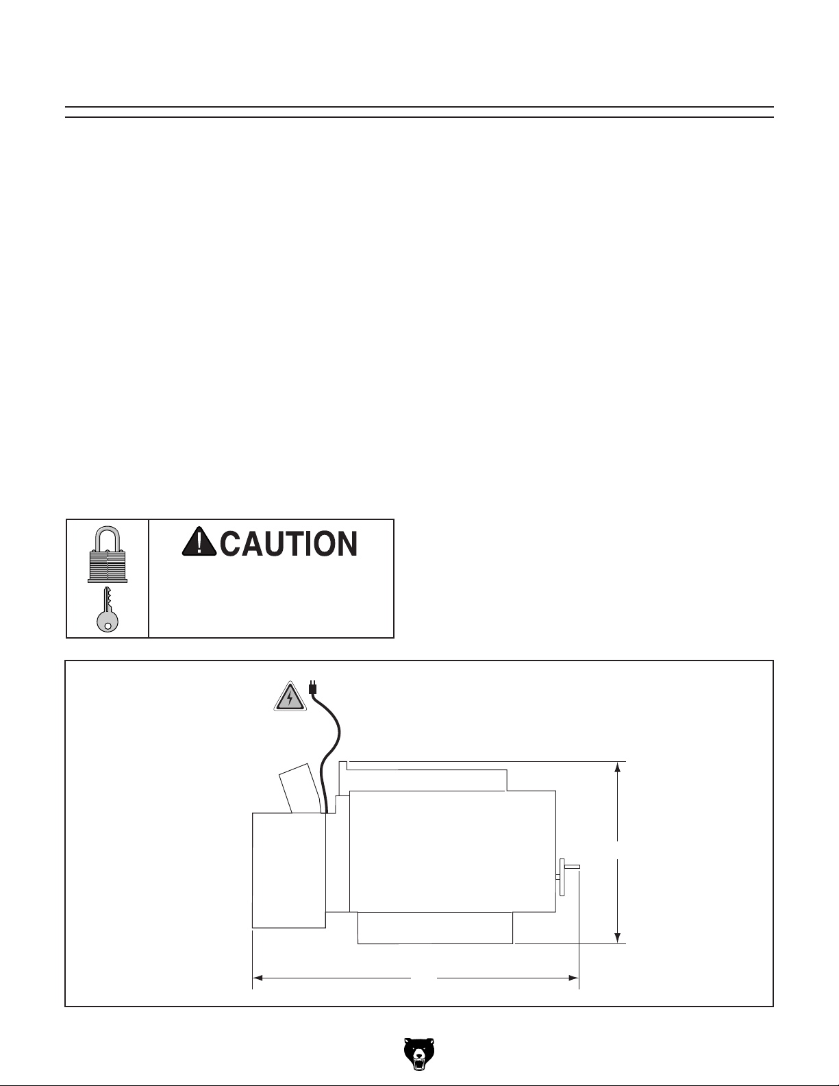
3. Loosen the cap screw on the right springloaded clamp as shown in Figure 20.
Right
Clamp
Tension
Access
Wheel
Hole
7. Use the old sandpaper as a pattern, or use
the pattern in Figure 21, to cut a new piece of
sandpaper to the necessary shape. After cut-
1
ting the 12
⁄2" angled sides, measure 2" along
the same sides and cut off the ends with a
knife.
"
2
1
⁄
12
12
2"
"
2
1
⁄
2"
3"
87"
Figure 21. Sandpaper pattern.
8. Insert the left corner of the new sandpaper
into the left clamp and tighten the cap screw
as shown in Figure 22. The angled side of
the sandpaper must be flush with the left
drum edge. If the sandpaper overlaps the
edge, you may have difficulty closing the
cover.
Figure 20. Loosening cap screw on right spring-
loaded clamp.
4. Remove the sandpaper from the clamp.
Note: You can use a flat head screwdriver to
loosen the clamp to free the sandpaper.
5. Rotate the drum to remove the sandpaper
belt.
-22-
Left
Clamp
Figure 22. Securing sandpaper in left clamp.
Model G0458 (Mfg. Since 5/11)
Page 25

9. Wrap the sandpaper around the drum (Figure
23), ensuring there are no bubbles or over-
lapping edges.
Figure 23. Wrapping sandpaper around drum.
10. When the sandpaper reaches the right side
of the drum, move the sandpaper out of the
way with a 4mm wrench and place it into the
access hole.
11. Rotate the drum toward you so the wrench
rests against the frame as shown in Figure
24.
12. Firmly hold down the sandpaper with both
hands, rotate the drum toward you, then wrap
the end of the sandpaper over the top of the
drum (Figure 25).
Figure 25. Wrapping sandpaper over tension
wheel.
13. Place the end of the sandpaper into the
clamp, secure it, and remove the hex wrench
from the access hole.
14. If the sandpaper does not fit into the right
clamp, you may have inserted the sandpaper
too deeply into the left clamp. Also, check to
make sure the length, width, and angled cuts
match the pattern in Figure 21. Make adjustments to the sandpaper if necessary.
Access
Hole
Figure 24. Hex wrench inserted into access hole
on right tension wheel.
Model G0458 (Mfg. Since 5/11)
If sandpaper completely covers the access
hole, you may have placed too little sandpaper into the left clamp. Unwrap the sandpaper
and redo Steps 8–13.
15. In either case, reinstall the sandpaper, repeat
Steps 9–13, and continue adjusting the paper
until it fits into the clamp.
16. When finished, reinstall the chip deflector,
secure it with the three cap screws, and close
the cover.
-23-
Page 26

SECTION 5: ACCESSORIES
Some aftermarket accessories can be
installed on this machine that could cause
it to function improperly, increasing the risk
of serious personal injury. To minimize this
risk, only install accessories recommended
for this machine by Grizzly.
NOTICE
Refer to the newest copy of the Grizzly
Catalog for other accessories available for
this machine.
Aluminum Oxide Sanding Rolls 3" x 22'
T23880—60 Grit: Use for thickness sanding and
glue removal.
T23881—80 Grit: Use for removing planer marks
and initial finish sanding.
T23882—100 Grit: Use for removing planer marks
and initial finish sanding.
T23883—120 Grit: Use for finish sanding.
T23884—150 Grit: Use for finish sanding.
T23885—180 Grit: Use for finish sanding.
T23886—220 Grit: Use for finish sanding.
G1163—1HP Floor Model Dust Collector
G0710—1HP Wall-Mount Dust Collector
Excellent point-of-use dust collectors that can
be used next to the machine with only a small
amount of ducting. Specifications: 450 CFM, 7.2"
static pressure, 2 cubic foot bag, and 30 micron
filter. Motor is 1HP, 110V/220V, 14A/7A.
PRO-STICK® Sanding Pad
Extend the life of your sandpaper! Just feed this
crepe-rubber cleaning pad through your drum
sander to remove dust build-up from the sandpaper without damage.
Size Model
15" X 20" X 1
Figure 27. PRO-STICK
T2199 2— Pow er Twi st
Smooth running with less vibration and noise
than solid belts. The Power Twist
customized in minutes to any size—just add or
remove sections to fit your needs. Size:
replaces all "A" sized V-belts. Requires one Power
®
V-belt to replace the stock V-belt on your
Twi st
Model G0458.
1
⁄8" ...................................... H2845
®
sanding pad.
®
V-Belt 1⁄2" x 4'
®
V-belts can be
1
⁄2" x 4';
Model G0710
Model G1163
Figure 26. Point-of-use dust collectors.
-24-
Figure 28. Power twist V-belt.
Model G0458 (Mfg. Since 5/11)
Page 27

SECTION 6: MAINTENANCE
Always disconnect power
to the machine before
performing maintenance.
Failure to do this may
result in serious personal injury.
Schedule
For safe and optimum performance from a
machine that is used on a daily basis, follow this
maintenance schedule and refer to any specific
instructions given in this section.
Daily Checks and Maintenance:
• Loose mounting bolts.
• Damaged sanding belt.
• Worn switch.
• Worn or damaged cords or plugs.
• Damaged V-belts.
• Any other unsafe condition.
• Oil the feed belt roller and drive bushings.
• Clean/vacuum dust buildup from inside cabinet and off of the motor.
Cleaning
Cleaning the Model G0458 is relatively easy.
Vacuum excess sawdust, and wipe off the remaining dust with a dry cloth.
Lubrication
The feed belt bushings should be lubricated daily
with a light machine oil. Lubricate the chains and
gears with a high-quality, lithium-based grease.
The bearings do not need lubrication.
Avoid using excess lubrication. Too much lubricant attracts sawdust and will clog the chain.
Bushings: Must be oiled daily or each time the
sander is used. Oil the bushings on each end of
the feed belt rollers and remove the pulley cover
and oil the drive bushings (see Figure 29).
Model G0458 (Mfg. Since 5/11)
Figure 29. Bushing locations.
-25-
Page 28
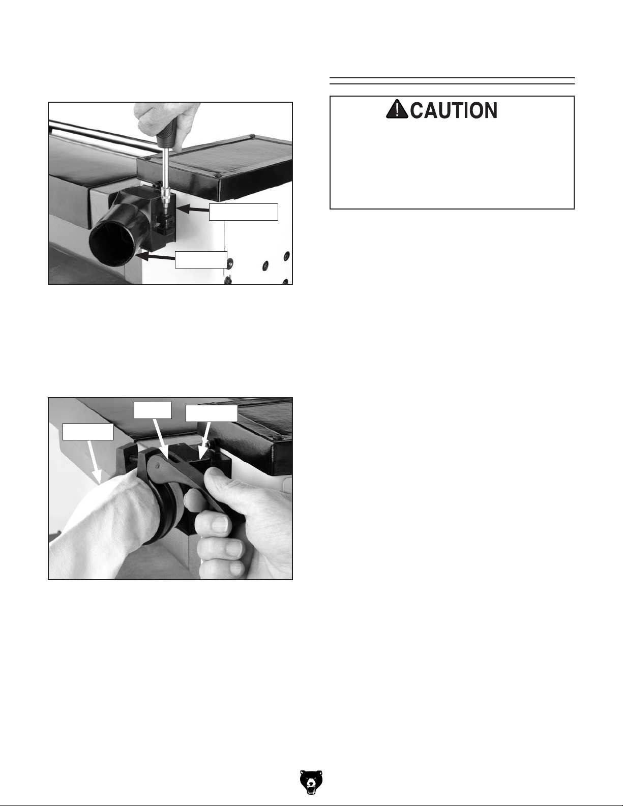
Feed Belt Drive: Lubricate with lithium grease
monthly. Wipe sawdust and dirt impregnated
grease off of the chain and gears shown in
Figures 30 & 31. Apply fresh lithium grease to the
gears and chain.
Figure 30. Feed belt drive chain.
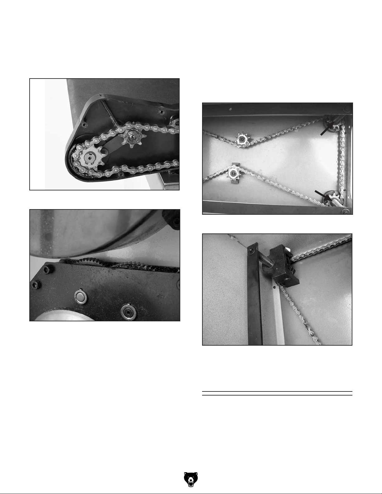
Table Lift Mechanism: Lubricate the table lift
screws, chain, and helical gear with lithium grease
every six months. Clean the chain and table lift
screws (Figure 32), then rub lithium grease onto
the chain links and screw threads. Clean the helical gear (Figure 33) and place a dab of grease on
the teeth. Move the table up or down to spread the
grease thoroughly throughout the mechanism.
Figure 31. Feed belt gears.
Figure 32. Table lift screws (only two shown).
Figure 33. Helical gear.
Sanding Belts
-26-
You can greatly increase the lifespan of your
sanding belts if you clean them often. Cleaning
pads (Accessories on Page 24) are the fastest
way to remove sawdust build-up.
Model G0458 (Mfg. Since 5/11)
Page 29

V-Belt Tensioning
Tools Needed: Qty
Hex Wrenches 4 & 8mm .............................. 1 Ea
Phillips Head Screwdriver ...................................1
Pry Bar ...............................................................1
Proper tension is important for optimum power
transmission. However, too much tension may
cause premature bearing failure.
3. Check the tension of the feed belt V-belt, then
adjust the tension by loosening the motor
mount cap screws shown in Figure 35 and
pushing down on the motor mount to tighten
the V-belts.
Feed Belt
V-Belt
Correct V-belt tension is achieved when the
V-belts can be deflected
the middle with moderate pressure. See Figure
34 for an example of how to perform a V-belt
deflection test with a straightedge and ruler.
Figure 34. Checking V-belt tension with a
straightedge and a ruler.
1
⁄2 "–3⁄4" when pushed in
Motor Mount
Cap Screws
Figure 35. Feed belt V-belt tension.
4. Tension the sanding drum V-belt by sliding
the idler roller (Figure 36) into the V-belt until
the belt is correctly tensioned, then replace
the pulley cover.
Idler
Roller
Always inspect V-belts for damage or deterioration when adjusting for tension. Should
you find evidence of cracking, abrasion or
damage from wood chips or other foreign
materials, replace the belt immediately. Belt
breakage may lead to mechanical damage
or operator injury.
To adjust V-belt tension:
1. Disconnect power to the sander!
2. Open the pulley cover.
Model G0458 (Mfg. Since 5/11)
Figure 36. Sanding drum V-belt tension.
NOTICE
New V-belts will often stretch and loosen
after moderate use. Check frequently after
installation and re-tension if necessary.
-27-
Page 30

SECTION 7: SERVICE
Review the troubleshooting and procedures in this section if a problem develops with your machine. If you
need replacement parts or additional help with a procedure, call our Technical Support at (570) 546-9663.
Note: Please gather the serial number and manufacture date of your machine before calling.
Troubleshooting
Motor & Electrical
Symptom Possible Cause Possible Solution
Machine does not start or
a breaker trips.
Machine stalls or is
underpowered.
1. Plug/receptacle is faulty or wired incorrectly.
2. Start capacitor is faulty.
3. Motor connection is wired incorrectly.
4. Power supply is faulty, or is switched OFF.
5. Safety switch key is at fault.
6. Motor ON/OFF switch is faulty.
7. Centrifugal switch is at fault.
8. Cable or wiring is open or has high
resistance.
9. Motor is at fault.
1. Wrong workpiece material.
2. Low power supply voltage.
3. Run capacitor is faulty.
4. Filter bags are at fault.
5. V-belts are slipping.
6. Plug or receptacle is at fault.
7. Motor connection is wired incorrectly.
8. Motor bearings are at fault.
9. Machine is overloaded.
10. Motor has overheated.
11. Centrifugal switch is at fault.
12. Motor is at fault.
1. Test power plug and receptacle for good
contact and correct wiring.
2. Test capacitor and replace if necessary.
3. Correct motor wiring (see Page 38).
4. Make sure hot lines and grounds are
operational and have correct voltage on all
legs.
5. Install or replace safety key, or replace
switch assembly.
6. Replace faulty ON/OFF switch.
7. Adjust or replace the centrifugal switch.
8. Check for disconnected or corroded
connections, troubleshoot wires for internal
or external breaks, then repair or replace
wiring.
9. Test, then repair or replace motor.
1. Only process wood with correct moisture
content, and no glues, or resins.
2. Make sure hot lines and grounds are
operational and have correct voltage on all
legs.
3. Test capacitor and replace if necessary.
4. Empty and clean filter bag.
5. Replace bad belts, align pulleys, and
re-tension the V-belts (see Pages 27 & 30).
6. Test power plug and receptacle for good
contact and correct wiring.
7. Correct motor wiring (see Page 38).
8. Rotate motor shaft for noisy or burnt
bearings, repair/replace as required.
9. Use new sandpaper with appropriate grit,
and reduce the feed rate/depth of sanding.
10. Check motor cooling air flow, let motor cool,
and reduce workload on machine.
11. Adjust/replace the centrifugal switch.
12. Test motor, and repair/replace if necessary.
-28-
Model G0458 (Mfg. Since 5/11)
Page 31

Symptom Possible Cause Possible Solution
Machine has vibration or
noisy operation.
1. Motor or component is loose.
2. V-belts are worn or loose.
3. Motor fan is rubbing on fan cover.
4. Pulley is loose.
5. Machine is incorrectly mounted to the floor.
6. Cast iron motor mount is at fault.
7. Motor bearings are at fault.
1. Inspect for stripped/damaged bolts/nuts,
replace/re-tighten with thread locking fluid.
2. Inspect belts, replace and re-tension (see
Pages 27 & 30).
3. Replace dented fan cover/damaged fan.
4. Remove pulley, replace shaft, pulley,
setscrew, and key as required, and realign.
5. Machine has loose anchor studs in floor, or
is sitting on uneven floor. Replace/tighten
relocate as required.
6. Using leverage and a small pry bar to
inspect, carefully replace loose/broken
mounts.
7. Check bearings, replace motor or bearings
as required.
Sanding Operations
Symptom Possible Cause Possible Solution
Vibration when sanding. 1. Loose drum bearings.
2. Worn drum bearings.
1. Tighten drum bearings.
2. Replace drum bearings.
Grinding, screeching,
or rubbing noise when
sanding drums are
powered up.
Short V-belt lifespan. 1. Pulleys not aligned correctly.
Machine lacks power;
drums stop turning under
load.
Feed belt slips under load. 1. Feed belt is too loose.
Feed belt tracks to one
side or hits the feed table
mounts.
Excessive snipe. 1. Lack of outfeed support.
Workpiece kicks out of
sander.
Sandpaper tears off drums
during operation.
Table elevation controls
are stiff and hard to adjust.
1. Drum bushings lack sufficient oil.
2. Drum bushings are worn and need
replacement.
2. Improperly tensioned.
1. V-belts loose.
2. Too much pressure on pressure plates.
2. Too much load.
1. Feed belt tracking is incorrect. 1. Track the feed belt so it runs straight (see
2. Too much pressure from pressure plates.
3. Too much pressure from the rear pressure
plate.
1. Not enough pressure from the pressure
plates.
1. Nail/staple in workpiece.
2. Sandpaper not tightened or fastened
correctly.
1. Table lift screws are dirty or loaded with
sawdust.
2. Chain idler sprocket cap screws have been
over tightened.
3. Elevation handle helical gear is dirty or
loaded with sawdust.
1. Oil the drum bushings (see Page 25).
2. Replace the drum bushings.
1. Align pulleys (see Page 31).
2. Properly tension V-belts (see Page 27).
1. Tighten V-belts (see Page 27).
2. Raise the pressure plates (Page 35).
1. Tension feed belt (see Page 32).
2. Decrease load.
Page 31).
1. Set up an outfeed table or have someone
catch the workpiece as it comes out.
2. Raise the pressure plates (Page 35).
3. Raise the rear pressure plate (Page 35).
1. Lower the pressure plates (Page 35).
1. Sand only clean workpieces.
2. Install the sandpaper correctly (see Page
22).
1. Clean and re-grease table lift screws (see
Page 26).
2. Adjust the cap screws on the idler sprocket
so it can spin freely.
3. Clean and re-grease the helical gear (see
Page 26).
Model G0458 (Mfg. Since 5/11)
-29-
Page 32

Replacing V-Belts
4. Remove the cap screws securing the bearing
bracket and rotate the bearing bracket 90˚.
Tools Needed: Qty
Hex Wrenches 4, 6 & 8mm .......................... 1 Ea
Phillips Head Screwdriver ...................................1
Pry Bar ...............................................................1
Inspect the V-belts closely; if you notice fraying,
cracking, glazing, or any other damage, replace
the belts. A worn/damaged V-belt will not provide
optimum power transmission from the motor to
the drum and feed belt.
V-belt removal and replacement is simply a matter of loosening the V-belts, rolling them off of
the pulleys, replacing them with new belts, then
retensioning them.
To replace the V-belts:
1. Disconnect power to the sander!
2. Open the pulley cover.
5. Slide the sanding drum V-belt off of the motor
pulley, then lift the motor mount to remove
the feed V-belt.
Note: You may need to use a pry bar to lift
the motor mount.
6. To replace the variable speed belt, remove
the cap screw securing the pulley shown in
Figure 38, then remove the outer half of the
pulley.
Variable
Speed Pulley
Note: If you plan on replacing the variable
speed belt, loosen the cap screw securing
the variable speed pulley (figure 38) before
loosening the motor mount cap screws.
3. Loosen the motor mount cap screws shown
in Figure 37 and loosen the cap screw securing the idler roller.
Bearing
Bracket
Motor Mount Cap Screws
Idler
Roller
Figure 38. Variable speed pulley.
7. Compress the spring behind the inner half
of the variable speed pulley, slide the outer
half of the pulley over the shaft and key, then
thread in the cap screw.
8. Install the new feed and drum V-belts, reattach the bearing bracket, and tension
according to the instructions on Page 27.
9. Tighten the variable speed pulley cap screw
and replace the pulley cover.
-30-
Figure 37. Belt drive system.
Model G0458 (Mfg. Since 5/11)
Page 33

Pulley Alignment
Tools Needed: Qty
Hex Wrenches 4 & 8mm .............................. 1 Ea
Phillips Head Screwdriver ...................................1
Pry Bar ...............................................................1
Pulley alignment is another important factor in
power transmission and belt life. The pulleys
should be parallel to each other and in the same
plane (coplaner) for optimum performance.
4. Remove the V-belts.
5. Loosen the set screws on the motor pulley
and align the motor pulley with the feed belt
pulley.
6. Loosen the set screws on the sanding belt
pulley and align the sanding belt pulley with
the motor pulley.
7. Tighten the set screws, replace the V-belts,
and repeat Step 3. Belts should be parallel
and aligned as shown in Figure 39.
Each pulley can be adjusted by loosening the set
screw that secures the pulley to the shaft, sliding
the pulley in/out, and retightening the set screw to
lock the pulley in place.
To align the pulleys:
1. Disconnect power to the sander!
2. Open the pulley cover.
3. Looking from the top, sight down the V-belts
and pulleys and check to see that the pulleys
are parallel and aligned with each other (see
Figure 39).
— If the pulleys are aligned, go to Step 9.
— If the pulleys are NOT aligned, perform
Steps 4 –8.
Sanding
Drum
Sanding
Drum
Pulley
8. Adjust the pulleys again, if necessary, until
they are all coplanar with each other.
9. Replace the pulley cover.
Feed Belt Tracking
Tools Needed: Qty
Wrench 8mm ......................................................1
Hex Wrench 4mm ...............................................1
The feed belt must track straight. If the feed belt
tracks to either side, then the tracking must be
corrected or the feed belt will become damaged
and have to be replaced.
Tracking the feed belt is a balancing process that
takes patience and a small degree of trial-anderror. Usually you must over-tighten the loose side
(the side the belt is tracking towards) to make the
feed belt move to the middle of the rollers, then
loosen that same side to make the feed belt stay
in position. If you adjust the bolt too much either
way, then you have to repeat the process until the
feed belt rides in the middle and stays there during continuous operation.
Motor
Alignment
Figure 39. The pulleys should be parallel and
aligned.
Model G0458 (Mfg. Since 5/11)
Motor Pulley
Setscrew
Note: Tracking affects tension, so tension must
always be adjusted after tracking.
To track the feed belt:
1. Turn the feed belt ON and watch it track. If
the belt moves to one side, immediately stop
the machine and adjust the belt tracking. If
the belt tracks evenly, leave it alone.
-31-
Page 34

2. Loosen the lock nut (Figure 40) on the side
that the feed belt tracks towards and tension
the tracking adjustment screw until the feed
belt tracks in the opposite direction.
Note: Small tracking changes may take up to
three minutes before they are noticeable.
To tension the feed belt:
1. Loosen the feed roller lock screws, shown in
Figure 41, on both sides of the feed belt.
Feed Belt
Feed Roller
Lock Screws
Lock Nut
Tensioning
Bolt
Lock Nut
Figure 40. Feed belt tracking adjustment bolt.
3. When the feed belt is near the middle of the
rollers or table, loosen the tracking adjustment screw until the feed belt stops moving
and tracks straight.
—If the feed belt tracks too far to the other
side, loosen the tracking adjustment screw
as necessary to bring it back. Repeat
Steps 2 & 3 until the tracking is correct.
Tracking
Adjustment
Screw
Feed Belt Tension
Tools Needed: Qty
Wrench 12mm ....................................................2
Hex Wrench 6mm ...............................................1
The feed belt will stretch when new and will eventually need to be tensioned. This is most obvious
if the feed belt starts slipping on the rollers.
When you tension the feed belt, focus on adjusting
the tensioning bolts in even increments. Adjusting
one side more than the other will cause tracking
problems, which will require you to take additional
steps to get the sander operating correctly.
Figure 41. Feed belt tensioning controls.
2. Use a permanent marker, paper correction
fluid, or fingernail polish to mark the feed belt
tensioning bolt on both sides. This step will
aid you in keeping track of the rotations as
you turn the bolts, so they remain as even as
possible.
3. Loosen the lock nuts and turn both of the
feed belt tensioning bolts clockwise one full
turn at a time until the feed belt no longer
slips during operation.
—If the feed belt starts tracking to one side,
back off the feed belt tensioning bolt that is
being adjusted.
—If the feed belt continues tracking to one
side, immediately turn the drum sander
Off and perform the tracking instructions.
4. Tighten the lock nuts to lock the feed belt
tensioning bolts in place.
Note: When tensioned properly the belt
should not lift off the table, slide back and
forth, or slip.
DO NOT over-tension the feed belt, this may
cause premature wearing of the belt, bushings, and cause strain on the motor.
-32-
Model G0458 (Mfg. Since 5/11)
Page 35

Feed Belt
5. Have an assistant lift the outside edge of the
table, then slide the feed belt off.
Replacement
Tools Needed: Qty
Wrench 12mm ....................................................2
Hex Wrench 6mm ...............................................1
An Assistant .......................................................1
Replacing the feed belt is a simple process, but
will require tensioning and tracking when completed.
To replace the feed belt:
1. Disconnect power to the sander!
2. Use a permanent marker, paper correction
fluid, or fingernail polish to mark the front of
the feed belt tensioning bolt (Figure 41) on
both sides. This step will aid you in returning
the bolts to their original position, reducing
the amount of tracking necessary.
6. Clean any dirt or dust off of the table and rollers, have an assistant lift the table, then slide
the new feed belt on.
7. Re-install and tighten all of the table cap
screws.
8. Tighten the feed belt adjustment bolts equally, then follow the tensioning instructions on
Page 32.
Note: The feed belt will stretch slightly when
new and will need to be re-tensioned after a
short amount of use.
9. Track the new feed belt according to the
instructions on Page 31.
Note: One side of the belt may need to be
tighter than the other for the belt to track
straight.
3. Loosen the lock nuts shown in Figure 41 and
turn both of the feed belt adjustment bolts
counterclockwise one full turn at a time to
release the tension from the feed belt.
4. Remove the outside table cap screws shown
in Figure 42 and loosen the corresponding
cap screws on the inside edge.
Table Cap
Screws
Figure 42. Feed belt table outside cap screws.
Model G0458 (Mfg. Since 5/11)
-33-
Page 36

Gauge Blocks
15
30
45
Table Adjustments
Tools Needed: Qty
6' Long 2x4 .........................................................1
Miter Saw (or Circular Saw) ................................1
Jointer .................................................................1
Table Saw ...........................................................1
The gauge blocks described here will be required
to complete the remaining service procedures in
this section.
To make the gauge blocks:
1. Edge joint the concave edge of the 2x4 flat on
a jointer, as shown in Figure 43.
Figure 43. Edge jointing on a jointer.
2. Place the jointed edge of the 2x4 against the
table saw fence and rip cut just enough off
the opposite side to square up the two edges
of the 2x4, as shown in Figure 44.
Aligning the drums parallel to the conveyor belt
(Figure 45) is critical for sanding accuracy. Care
should be taken to make the tolerances as close
as possible (within 0.002" from one side to the
other) when adjusting the drum height.
Sanding Drum
Conveyor Belt
Figure 45. Drum parallel to conveyor belt.
Tools Needed: Qty
Hex Wrenches 3 & 6mm .............................. 1 Ea
Gauge Blocks .....................................................2
Feeler Gauge Set ...............................................1
To align the drums:
1. Disconnect power to the sander!
Opposite
Edge Rip
Cut with
Table Saw
Previously
Jointed Edge
Held Against
Fence
Figure 44. Rip cutting on a table saw.
3. Cut the 2x4 into two even pieces to make two
36" long wood gauge blocks.
Note: Steps 1 & 2 can be skipped, but hav-
ing the gauge blocks at an equal height is
critical to the accuracy of your adjustments.
-34-
2. Remove the sandpaper from the drum and
place the gauge blocks as shown in Figure
46.
Figure 46. Gauge blocks placed under drums.
Model G0458 (Mfg. Since 5/11)
Page 37

3. Raise the table until the gauge blocks just
touch the drum.
Pressure Plate
Note: A good way to know when they are
touching is to rock the drum back and forth
while raising the table until you hear or feel
contact with the gauge blocks.
4. Lower the table one full crank of the handwheel
(taking handwheel free-play into consideration; or in other words, wait until the chain
starts moving before starting to count the
handwheel rotation).
5. Starting at one end, find the largest size feeler
gauge that can pass between the drum and
your gauge block. (The feeler gauge should
slide with moderate resistance, without forcing the drum to roll.)
6. Repeat Step 5 at the other end of the drum.
—If the difference between the two sizes is
0.002" or less, then no adjustment is necessary.
Adjustments
Tools Needed: Qty
Wrench 8mm ......................................................1
Hex Wrench 4mm ...............................................1
Gauge Blocks (see Page 34) .............................2
Feeler Gauge Set ...............................................1
When properly positioned, the pressure plates
should be approximately 0.004" lower than the
drum.
Adjusting the pressure plates is a fine balance
between too much pressure and not enough. Too
much pressure can cause problems like snipe
or overloading the motor, not enough pressure
may allow the workpiece to kick out of the sander
towards the operator.
The pressure plates have been set correctly at the
factory. Do not adjust the pressure plates unless
absolutely necessary.
— If the difference between the two sizes is
more than 0.002", then one end must be
adjusted to within 0.002" from the other.
Continue to the next step.
7. Loosen the table cap screws and adjust the
height of the table by rotating the adjustment
knob shown in Figure 47.
Table Cap
Screws
Table Height
Adjustment
Knob
To check pressure plate adjustment:
1. Disconnect power to the sander!
2. Place the gauge blocks on the feed belt as
shown in Figure 46.
3. Raise the table until the gauge blocks just
touch the rear pressure plate.
4. Find the largest size feeler gauge that can
pass between the drum and your gauge block.
(The feeler gauge should slide with moderate
resistance, without forcing the drum to roll.)
—If the gap is 0.004" (0.1mm) or less, then
no adjustment of the rear pressure plate is
necessary.
— If the gap is more than 0.004" (0.1mm),
then the rear pressure plate must be
adjusted.
Figure 47. Table height adjustment knob.
8. Tighten the table cap screws and repeat
Steps 5 & 6.
Model G0458 (Mfg. Since 5/11)
-35-
Page 38

5. Raise the table until the gauge blocks just
touch the drum.
6. Find the largest size feeler gauge that can
pass between the front pressure plate and
your gauge block. (The feeler gauge should
slide with moderate resistance, without forcing the drum to roll.)
—If the gap is 0.004" (0.1mm) or less, then
no adjustment of the front pressure plate is
necessary.
— If the gap is more than 0.004" (0.1mm),
then the front pressure plate must be
adjusted.
To adjust the rear pressure plate:
1. Disconnect power to the sander!
2. Loosen the lock nuts and tighten the cap
screws on both ends of the rear pressure
plate shown in Figure 48 to raise the pressure plate, or loosen the cap screw to lower
the pressure plate.
To adjust the front pressure plate:
1. Disconnect power to the sander!
2. Loosen the lock nuts and tighten the cap
screws on both ends of the front pressure
plate shown in Figure 49 to raise the pressure plate, or loosen the cap screw to lower
the pressure plate.
3. Adjust the front pressure plate until it is equal
to, or up to 0.004" (0.1mm) lower than the
height of the drum.
Lock Nut
Front Pressure
Plate Adjustment
Front
Pressure
Plate
Cap Screw
Rear
Pressure
Plate
Lock Nut
Figure 48. Rear pressure plate adjustments.
3. Adjust the rear pressure plate until it is equal
to, or up to 0.004" (0.1mm) lower than the
height of the drum.
Rear Pressure
Plate Adjustment
Cap Screw
Figure 49. Front pressure plate adjustments.
-36-
Model G0458 (Mfg. Since 5/11)
Page 39

These pages are current at the time of printing. However, in the spirit of improvement, we may make changes to the electrical systems of future machines. Compare the manufacture date of your machine to the one
number and manufacture date of your
machine before calling. This information can be found on the main machine label.
machine
SECTION 8: WIRING
stated in this manual, and study this section carefully.
If there are differences between your machine and what is shown in this section, call Technical Support at
(570) 546-9663 for assistance BEFORE making any changes to the wiring on your machine. An updated
wiring diagram may be available. Note: Please gather the serial
Wiring Safety Instructions
SHOCK HAZARD. Working on wiring that is connected to a power source is extremely dangerous.
Touching electrified parts will result in personal
injury including but not limited to severe burns,
electrocution, or death. Disconnect the power
from the machine before servicing electrical components!
MODIFICATIONS. Modifying the wiring beyond
what is shown in the diagram may lead to unpredictable results, including serious injury or fire.
This includes the installation of unapproved aftermarket parts.
WIRE CONNECTIONS. All connections must
be tight to prevent wires from loosening during
machine operation. Double-check all wires disconnected or connected during any wiring task to
ensure tight connections.
CIRCUIT REQUIREMENTS. You MUST follow
the requirements at the beginning of this manual when connecting your machine to a power
source.
WIRE/COMPONENT DAMAGE. Damaged wires
or components increase the risk of serious personal injury, fire, or machine damage. If you notice
that any wires or components are damaged while
performing a wiring task, replace those wires or
components.
MOTOR WIRING. The motor wiring shown in
these diagrams is current at the time of printing
but may not match your machine. If you find this
to be the case, use the wiring diagram inside the
motor junction box.
CAPACITORS/INVERTERS. Some capacitors
and power inverters store an electrical charge for
up to 10 minutes after being disconnected from
the power source. To reduce the risk of being
shocked, wait at least this long before working on
capacitors.
EXPERIENCING DIFFICULTIES. If you are experiencing difficulties understanding the information
included in this section, contact our Technical
Support at (570) 546-9663.
The photos and diagrams
included in this section are
best viewed in color. You
can view these pages in
color at www.grizzly.com.
Model G0458 (Mfg. Since 5/11)
-37-
Page 40

wiring diagram
Wiring Diagram
Neutral
5-15 Plug
Hot
Ground
110
VAC
Ground
Overload Switch
(viewed from behind)
Paddle Switch
(viewed from behind)
-38-
READ ELECTRICAL SAFETY
ON PAGE 37!
Model G0458 (Mfg. Since 5/11)
Page 41

G0458 Parts Breakdown
221
7
6
5
82
271
247
75
100
263
165
248
225
277
268
269
13
14
238
103
101
265
264
15
239
100-6
100-3
100-2
100-5
100-4
214
279
159
141
113
215
280
160
134
133
216
219
161
243
137
217
282
220
244
114
285
284
97
266
276
267
288
245
115
286
98
270
295
162
287
135
110
99
272
246
136
102
237
100-1
212
211
208
298
126
9
249
94
95
185
132
128
127
290
109
92
93
184
182
224
130
129
111
89
96
213
283
183
157
241
138
139
140
88
89
278
158
242
106
116
79
199
198
178
167
24
60
201
203
191
179
168
235
146
117
281
64
147
143
142
251
80
69
202
83
74
149
148
144
118
73
68
65
90
72
67
204
181
150
119
91
84
66
205
153
151
88
206
152
123
120
71
88
85
297
154
124
87
209
207
155
125
122
121
112
210
156
131
175
234
262
32
19
18
176
79
258
260
256
31
21
20
189
78
77
223
253
22
63
200
190
177
86
81
76
105
104
23
62
61
196
195
194
193
192
53
52
51
50
4
2
3
222
108
11
39
35
164
250
54
40
34
197
218
59
107
43
42
41
33
70
236
58
44
273
163
12
57
45
56
274
226
227
48
47
228
36
25
1
46
26
8
169
275
229
49
31
37
27
186
233
170
230
38
22
28
187
172
171
257
16
173
231
259
29
10
188
174
166
232
261
255
254
24
30
17
Model G0458 (Mfg. Since 5/11)
-39-
Page 42

REF PART # DESCRIPTION REF PART # DESCRIPTION
1 PLW06M LOCK WASHER 10MM 51 PK07M KEY 6 X 6 X 20
2 PS05M PHLP HD SCR M5-.8 X 8 52 P0458052 FAN COVER
3 PW02M FLAT WASHER 5MM 53 PSB18M CAP SCREW M4-.7 X 8
4 PSB03M CAP SCREW M5-.8 X 8 54 PSS20M SET SCREW M8-1.25 X 8
5 P0458005 BEARING RETAINER 56 P0458056 COLLECTOR TUBE
6 P0458006 BEARING CAP 57 PS05M PHLP HD SCR M5-.8 X 8
7 PSB33M CAP SCREW M5-.8 X 12 58 PS47M PHLP HD SCR M6-1 X 25
8 PS47M PHLP HD SCR M6-1 X 25 59 P0458059 COLLECTOR TUBE
9 PEC06M E-CLIP 20MM 60 P0458060 LINK
10 PLW04M LOCK WASHER 8MM 61 P0458061 PIN
11 P0458011 SPONGE STRIP 62 PLW01M LOCK WASHER 5MM
12 P0458012 SPONGE STRIP 63 PSB38M CAP SCREW M5-.8 X 25
13 PAW06M HEX WRENCH 6MM 64 PSS02M SET SCREW M6-1 X 6
14 PAW05M HEX WRENCH 5MM 65 P0458065 BRACKET
15 PAW04M HEX WRENCH 4MM 66 P0458066 ADJUSTING ROD
16 PSB100M CAP SCREW M8-1.25 X 15 67 PN06M HEX NUT M5-.8
17 PW01M FLAT WASHER 8MM 68 P0458068 RETAINER
18 P0458018 PULLEY 69 P0458069 SPECIAL NUT
19 P0458019 PULLEY 70 P0458070 DUST PORT
20 P0458020 COMPRESSION SPRING 71 PSB01M CAP SCREW M6-1 X 16
21 P0458021 SPACER 72 PS09M PHLP HD SCR M5-.8 X 10
22 P6003 BEARING 6003ZZ 73 PW02M FLAT WASHER 5MM
23 P0458023 SHAFT 74 P0458074 KNOB 8MM
24 P6003 BEARING 6003ZZ 75 P0458075 GRIZZLY.COM LABEL
25 P0458025 THRUST BALL BEARING 76 P0458076 SPEED SCALE
26 P0458026 PULLEY 77 P0458077 GEAR
27 P0458027 COGGED V-BELT 400VK15-22 78 PSB64M CAP SCREW M10-1.5 X 25
28 P0458028 PULLEY 79 PSB02M CAP SCREW M6-1 X 20
29 P0458029 BUSHING 80 PSS07M SET SCREW M5-.8 X 5
30 P0458030 GEAR 52/12T 81 PW04M FLAT WASHER 10MM
31 PK02M KEY 5 X 5 X 40 82 P0458082 SIDE COVER
32 P0458032 SHAFT 83 P0458083 GEAR
33 PSB95M CAP SCREW M5-.8 X 30 84 P0458084 SIDE COVER
34 P0458034 INSIDE COVER 85 P0458085 CHAIN 132-410
35 PSB38M CAP SCREW M5-.8 X 25 86 P0458086 SIDE CASTING
36 P0458036 SHAFT 87 PW03M FLAT WASHER 6MM
37 P0458037 SPACER 88 PSB04M CAP SCREW M6-1 X 10
38 PW02M FLAT WASHER 5MM 89 PW03M FLAT WASHER 6MM
39 P0458039 GEAR 70T 90 P0458090 TURNMETER COVER
40 P6004 BEARING 6004ZZ 91 PS08M PHLP HD SCR M5-.8 X 12
41 P0458041 BEARING COVER 92 P0458092 SPROCKET
42 P0458042 GEAR 58/12T 93 P0458093 SPACER
43 P0458043 PULLEY 94 P0458094 IDLER BRACKET
44 P0458044 SPACER 95 PSS14M SET SCREW M8-1.25 X 12
45 P0458045 INSIDE COVER 96 PK11M KEY 6 X 6 X 40
46 P0458046 SPROCKET 97 PVA44 V-BELT A44
47 P0458047 FAN 98 P0458098 PULLEY
48 PSB64M CAP SCREW M10-1.5 X 25 99 PVM26 V-BELT M-26 3L260
49 PR05M EXT RETAINING RING 15MM 100 P0458100 MOTOR 1-1/2HP 115V
50 PSS01M SET SCREW M6-1 X 10
G0458 Parts List
-40-
Model G0458 (Mfg. Since 5/11)
Page 43

G0458 Parts List
REF PART # DESCRIPTION REF PART # DESCRIPTION
100-1 P0458100-1 MOTOR BRACKET 148 P0458148 SPECIAL NUT
100-2 P0458100-2 CAPACITOR 25MFD 250VAC 149 P0458149 EXTENSION SPRING
100-3 PC300S CAPACITOR 300MFD 125VAC 150 P0458150 TENSION WHEEL ASSY
100-4 P0458100-4 MOTOR FAN 151 P0458151 CHAIN PROTECTOR
100-5 P0458100-5 FAN COVER 152 PS05M PHLP HD SCR M5-.8 x 8
100-6 P0458100-6 CAP COVER /JUNCTION BOX 153 PS19M PHLP HD SCR M5-.8 x 6
101 P0458101 LOWER CASTING 154 PR09M EXT RETAINING RING 20MM
102 P0458102 SHAFT 155 P0458155 SPACER
103 P0458103 HANDWHEEL 156 P0458156 ROLLER
104 P0458104 SWITCH KEY 157 PSB31M CAP SCREW M8-1.25 X 25
105 P0458105 SWITCH 158 PW01M FLAT WASHER 8MM
106 P0458106 SPROCKET 159 P0458159 EXTENSION BRACKET
107 P0458107 COVER 160 PW01M FLAT WASHER 8MM
108 PB95M HEX BOLT M5-.8 X 16 161 PSB11M CAP SCREW M8-1.25 X 16
109 P6103043 BEARING 6904ZZ 162 P0458162 ELEVATING SCREW
110 PR03M EXT RETAINING RING 12MM 163 PN01M HEX NUT M6-1
111 P0458111 BEARING COVER 164 P0458164 EYE BOLT M6-1 X 50
112 PS68M PHLP HD SCR M6-1 X 10 165 P0458165 CONVEYOR BELT
113 P0458113 GEAR 166 P0502058 BEARING 6205ZZ
114 PSS07M SET SCREW M5-.8 X 5 167 PSB06M CAP SCREW M6-1 X 25
115 P0458115 WORM 168 PSB06M CAP SCREW M6-1 X 25
116 P0458116 BRACKET 169 P0458169 STRAIN RELIEF
117 PSB130M CAP SCREW M10-1.5 X 16 170 P0458170 BEARING SEAT
118 P0458118 SIDE COVER 171 PR11M EXT RETAINING RING 25MM
119 PHTEK26M TAP SCREW M5- X 10 172 PSB06M CAP SCREW M6-1 X 25
120 PS38M PHLP HD SCR M4-.7 X 10 173 P0458173 LOCKING BLOCK
121 P0458121 DUST COVER 174 P0458174 FIXED PAN
122 P0458122 FIXED COLLAR 175 P0458175 FIXED PAN
123 PR05M EXT RETAINING RING 15MM 176 P0458176 HEAD SHAFT
124 P0458124 SPROCKET 177 PK99M KEY 6 X 6 X 15
125 P0458125 BUSHING 178 P0458178 DRUM
126 P0458126 SPACER 179 P0458179 SANDPAPER
127 P0458127 CHAIN COVER 181 P0458181 FIXED PAN
128 PSB03M CAP SCREW M5-.8 X 8 182 P0458182 EXTENSION SPRING
129 PW02M FLAT WASHER 5MM 183 PSB33M CAP SCREW M5-.8 X 12
130 P0458130 GUIDE PLATE 184 PSB06M CAP SCREW M6-1 X 25
131 PW02M FLAT WASHER 5MM 185 P0458185 FIXED PAN
132 PSB79M CAP SCREW M5-.8 X 35 186 P0458186 HEAD COVER
133 PR09M EXT RETAINING RING 20MM 187 P0458187 CHIP GUIDE BRACKET
134 P0458134 EXTENSION BRACKET 188 P0458188 SIDE COVER
135 P0458135 BUSHING 189 P0458189 SPONGE STRIP
136 P0458136 ROLLER 190 PSB04M CAP SCREW M6-1 X 10
137 P0458137 TABLE 191 P0458191 PRESSURE PLATE
138 PB09M HEX BOLT M8-1.25 X 20 192 P0458192 BRACKET
139 PN03M HEX NUT M8-1.25 193 P0458193 ROLLER PIN
140 PSB11M CAP SCREW M8-1.25 X 16 194 P0458194 BUSHING
141 PW01M FLAT WASHER 8MM 195 P0458195 ROLLER
142 PSB02M CAP SCREW M6-1 X 20 196 PS40M PHLP HD SCR M5-.8 X 16
143 PW03M FLAT WASHER 6MM 197 PSB01M CAP SCREW M6-1 X 16
144 P0458144 SPROCKET 198 P0458198 HINGE
146 P0458146 CHAIN 199 PS05M PHLP HD SCR M5-.8 X 8
147 P0458147 SPACER
Model G0458 (Mfg. Since 5/11)
-41-
Page 44

G0458 Parts List
REF PART # DESCRIPTION REF PART # DESCRIPTION
200 PSB33M CAP SCREW M5-.8 X 12 247 P0458247 ROD
201 P0458201 CHIP DEFLECTOR PLATE 248 PSB79M CAP SCREW M5-.8 X 35
202 PFH43M FLAT HD SCR M6-1 X 10 249 P0458249 SPACER
203 PFH07M FLAT HD SCR M5-.8 X 10 250 P0458250 PIN
204 PSS24M SET SCREW M5-.8 X 25 251 PLW06M LOCK WASHER 10MM
205 PN06M HEX NUT M5-.8 253 P0458253 PULLEY COVER
206 P0458206 BUSHING 254 P0458254 PULLEY SHAFT
207 PSB142M CAP SCREW M10-1.5 X 10 255 P0458255 PULLEY
208 PSB64M CAP SCREW M10-1.5 X 25 256 PB04M HEX BOLT M6-1 X 10
209 PSB33M CAP SCREW M5-.8 X 12 257 PB04M HEX BOLT M6-1 X 10
210 P0458210 PRESSURE PLATE 258 PB04M HEX BOLT M6-1 X 10
211 P0458211 LINK 259 PW03M FLAT WASHER 6MM
212 PSB04M CAP SCREW M6-1 X 10 260 PW03M FLAT WASHER 6MM
213 P0458213 SPRING SHEET 261 P0458261 BEARING 6002ZZ
214 P0458214 HEADCASTING 262 PW21M FLAT WASHER 32MM
215 P0502058 BEARING 6205ZZ 263 P0458263 STAND
216 P0458216 BEARING COVER 264 P0458264 FRONT SUPPORTING PLATE
217 PSB26M CAP SCREW M6-1 X 12 265 P0458265 SIDE SUPPORTING PLATE
218 P0458218 COLLAR 266 P0458266 FRONT PLATE
219 PN06M HEX NUT M5-.8 267 P0458267 SIDE PLATE
220 PSS34M SET SCREW M5-.8 X 16 268 PCB06M CARRIAGE BOLT M8-1.25 X 16
221 PW02M FLAT WASHER 5MM 269 PFN01M FLANGE NUT M8-1.25
222 P0458222 DUST HOSE CLAMP 270 PB09M HEX BOLT M8-1.25 X 20
223 P0458223 SWITCH RESET 271 PN03M HEX NUT M8-1.25
224 PLW04M LOCK WASHER 8MM 272 PW01M FLAT WASHER 8MM
225 P0458225 OPEN END WRENCH 8/12MM 273 P0458273 DUST BAG
226 PS19M PHLP HD SCR M5-.8 X 6 274 PW02M FLAT WASHER 5MM
227 PTLW02M EXT TOOTH WASHER 5MM 275 P0458275 G0458 LABEL
228 P0458228 SPACER 276 P0458276 GRIZZLY LOGO
229 PSB33M CAP SCREW M5-.8 X 12 277 P0458277 MACHINE ID LABEL
230 PW02M FLAT WASHER 5MM 278 PLABEL-11 SAFETY GLASSES LABEL
231 PS05M PHLP HD SCR M5-.8 X 8 279 PLABEL-12 READ MANUAL LABEL
232 P0458232 STRAIN RELIEF 280 PLABEL-32 DUST MASK LABEL
233 P0458233 POWER CORD 281 PLABEL-14 ELECTRICITY LABEL
234 P0458234 COMPRESSION SPRING 282 PS98M PHLP HD SCR M3-.5 X 16
235 P0458235 PLATE 283 PN07M HEX NUT M3-.5
236 PW03M FLAT WASHER 6MM 284 P0458284 CONNECTING CORD
237 PRP02M ROLL PIN 3 X 16 285 PW02M FLAT WASHER 5MM
238 PW02M FLAT WASHER 5MM 286 PB112M HEX BOLT M5-.8 X 12
239 PSB33M CAP SCREW M5-.8 X 12 287 PSS02M SET SCREW M6-1 X 6
241 P0458241 ROD 288 P0458288 LOCK NUT 5/8-8
242 PSB33M CAP SCREW M5-.8 X 12 290 P0458290 BUSHING
243 P0458243 PLATE 295 P0458295 WAVE WASHER 40MM
244 PW02M FLAT WASHER 5MM 297 P0458297 SPRING RETAINER
246 PN06M HEX NUT M5-.8 298 PCAP50M CAP SCREW M5-.8 X 10
Safety labels help reduce the risk of serious injury caused by machine hazards. If any label comes
off or becomes unreadable, the owner of this machine MUST replace it in the original location
before resuming operations. For replacements, contact (800) 523-4777 or www.grizzly.com.
-42-
Model G0458 (Mfg. Since 5/11)
Page 45

WARRANTY CARD
Name _____________________________________________________________________________
Street _____________________________________________________________________________
City _______________________ State _________________________ Zip _____________________
Phone # ____________________ Email _________________________________________________
Model # ____________________ Order # _______________________ Serial # __________________
The following information is given on a voluntary basis. It will be used for marketing purposes to help us develop
better products and services. Of course, all information is strictly confidential.
1. How did you learn about us?
____ Advertisement ____ Friend ____ Catalog
____ Card Deck ____ Website ____ Other:
2. Which of the following magazines do you subscribe to?
____ Cabinetmaker & FDM
____ Family Handyman
____ Hand Loader
____ Handy
____ Home Shop Machinist
____ Journal of Light Cont.
____ Live Steam
____ Model Airplane News
____ Old House Journal
____ Popular Mechanics
3. What is your annual household income?
____ $20,000-$29,000 ____ $30,000-$39,000 ____ $40,000-$49,000
____ $50,000-$59,000 ____ $60,000-$69,000 ____ $70,000+
CUT ALONG DOTTED LINE
4. What is your age group?
____ 20-29 ____ 30-39 ____ 40-49
____ 50-59 ____ 60-69 ____ 70+
5. How long have you been a woodworker/metalworker?
____ 0-2 Years ____ 2-8 Years ____ 8-20 Years ____20+ Years
6. How many of your machines or tools are Grizzly?
____ 0-2 ____ 3-5 ____ 6-9 ____10+
____ Popular Science
____ Popular Woodworking
____ Precision Shooter
____ Projects in Metal
____ RC Modeler
____ Rie
____ Shop Notes
____ Shotgun News
____ Today’s Homeowner
____ Wood
____ Wooden Boat
____ Woodshop News
____ Woodsmith
____ Woodwork
____ Woodworker West
____ Woodworker’s Journal
____ Other:
7. Do you think your machine represents a good value? _____Yes _____No
8. Would you recommend Grizzly Industrial to a friend? _____ Yes _____No
9. Would you allow us to use your name as a reference for Grizzly customers in your area?
Note: We never use names more than 3 times. _____Yes _____No
10. Comments: _____________________________________________________________________
_________________________________________________________________________________
_________________________________________________________________________________
_________________________________________________________________________________
Page 46

FOLD ALONG DOTTED LINE
FOLD ALONG DOTTED LINE
Place
Stamp
Here
GRIZZLY INDUSTRIAL, INC.
P.O. BOX 2069
BELLINGHAM, WA 98227-2069
Send a Grizzly Catalog to a friend:
Name_______________________________
Street_______________________________
City______________State______Zip______
TAPE ALONG EDGES--PLEASE DO NOT STAPLE
Page 47

WARRANTY & RETURNS
Grizzly Industrial, Inc. warrants every product it sells for a period of 1 year to the original purchaser from
the date of purchase. This warranty does not apply to defects due directly or indirectly to misuse, abuse,
negligence, accidents, repairs or alterations or lack of maintenance. This is Grizzly’s sole written warranty
and any and all warranties that may be implied by law, including any merchantability or fitness, for any particular purpose, are hereby limited to the duration of this written warranty. We do not warrant or represent
that the merchandise complies with the provisions of any law or acts unless the manufacturer so warrants.
In no event shall Grizzly’s liability under this warranty exceed the purchase price paid for the product and
any legal actions brought against Grizzly shall be tried in the State of Washington, County of Whatcom.
We shall in no event be liable for death, injuries to persons or property or for incidental, contingent, special,
or consequential damages arising from the use of our products.
To take advantage of this warranty, contact us by mail or phone and give us all the details. We will then issue
you a “Return Number,’’ which must be clearly posted on the outside as well as the inside of the carton. We
will not accept any item back without this number. Proof of purchase must accompany the merchandise.
The manufacturers reserve the right to change specifications at any time because they constantly strive to
achieve better quality equipment. We make every effort to ensure that our products meet high quality and
durability standards and we hope you never need to use this warranty.
Please feel free to write or call us if you have any questions about the machine or the manual.
Thank you again for your business and continued support. We hope to serve you again soon.
Page 48

Buy Direct and Save with Grizzly®– Trusted, Proven and a Great Value!
~Since 1983~
Visit Our Website Today For
Current Specials!
ORDER
24 HOURS A DAY!
1-800-523-4777
 Loading...