

Page 1
BHS 60
73701666-04
Operating Instructions - Translation of the original Operating Instructions
Read operating instructions before use!
GB
Lire attentivement le mode d‘emploi avant chaquemise en service !
Mode d‘emploi - Traduction du mode d’emploi d’origine
FR
Prima della messa in funzione leggere le istruzioni per l‘utilizzo!
Istruzioni per l’uso - Traduzione delle istruzioni per l‘uso originali.
IT
Vor Inbetriebnahme Gebrauchsanweisung lesen !
DE
Gebrauchsanweisung - Originalbetriebsanleitung
Heckenschere
Taille-Haie
Tagliasiepi
Hedge Trimmer
Page 2

Page 3
1
1
Page 4
2
2
3
5
4
6
Page 5

3
8
9
7
Page 6

1. AN UNSERE KUNDEN
Wir möchten uns für Ihre Kaufentscheidung
bedanken.
Bei der Herstellung unserer HECKEN-
SCHERE haben wir zu Ihrem persönlichen
Schutz die geltenden Sicherheitsnormen angewandt.
In dieser
Betriebsanleitung sind alle für den
einwandfreien Betrieb Ihrer HECKENSCHE-
RE erforderlichen
Arbeiten für Montage,
Gebrauch und Wartung beschrieben und
illustriert.
FÜR EIN BESSERES VERSTÄNDNIS
Die Abbildungen zur Montage und Beschreibung der Maschine befinden sich am Anfang
dieses Handbuchs.
Beachten Sie bitte diese Seiten beim Lesen
der Montage- und Bedienungsanleitungen.
Sollte Ihre HECKENSCHERE eine Reparatur oder Serviceleistung benötigen, wenden
Sie sich bitte an Ihren Händler oder eine autorisierte Kundendienststelle.
2. WESENTLICHE SICHERHEITSVORKEHRUNGEN
HINWEISE:
A1 - Der Gebrauch der HECKENSCHERE kann schwere Personen-
schäden verursachen und setzt
daher die Beachtung der folgendenSicherheitsvorschriften voraus:
A2 - Wer die HECKENSCHERE
verwenden will, muss zuerst die
Gebrauchs- und Wartungsanleitungen aufmerksam lesen und sich für
einen korrekten Gebrauch des Geräts genauestens mit den Steuerungen vertraut machen.
A2.1 - Dieses Handbuch zum späteren Nachschlagen aufbewahren.
A3 - Verhindern Sie den Gebrauch
der HECKENSCHERE durch Kinder und Personen, die mit den hieraufgeführten Anweisungen nicht
vertraut sind.
GEFAHR:
A4 - Verwenden Sie die HECKEN-
SCHERE nicht in der Nähe von Per-
sonen (insbesondere Kindern) und
Tieren.
Während des Betriebs sollte stets
ein Mindestabstand von 10 m zwischen der Maschine und anderen
Personen eingehalten werden.
A5 - Achten Sie besonders auf
mögliche Gefahren, die aufgrund
des Maschinengeräuschs überhört
werden könnten.
A6 - Beseitigen Sie alle Gefahrenquellen, Kabel, Elektrokabel aus
dem Arbeitsbereich.
A7 - Für Verletzungen an anderenPersonen oder Gegenständen oder
für Gefahren haftet der Bediener.
ANWENDUNG:
B1 - Verwenden Sie die HECKEN-
SCHERE nur zum Schneiden von-
Hecken, kleineren Bäumen und
Sträuchern. Das Gerät darf nicht
für andere Zwecke angewandt werden.
B2 - Tragen Sie eine für den Gebrauch der HECKENSCHERE geeignete Kleidung sowie Schutzausrüstung. Während der Benützung ist
anliegende und keine lose Kleidung
zu tragen. Tragen Sie keine Sachen, die sich in den beweglichen
Teilen verfangen können.
Gebrauchsanweisung
DE-1
ALLGEMEINE NORMEN
Page 7
B3 – Zugelassene Schutzbrillen
oder Visiere tragen.
B3.1 – Zugelassenen Ohrenschutzgegen Lärm tragen.
B3.2 – Besteht die Gefahr fallender
Gegenstände ist ein Schutzhelm
aufzusetzen.
B4 – Widerstandsfähige Schuhe
mit rutschfesten Sohlen tragen.
B5 – Widerstandsfähige Handschuhe tragen.
B6 - Der Benutzer der HECKENSCHERE muss in guter körper-li-
cher Verfassung sein.
VERWENDEN SIE DAS GERÄT
NICHT bei Müdigkeit, Unwohlsein
oder unter Einwirkung von Alkohol
bzw. anderen Rauschmitteln.
B7 - ACHTUNG Die Abgase sind
giftig und wirken erstickend. Bei
Einatmen können sie auch tödliche
Auswirkungen haben. Der Motor
darf in geschlossenen oder wenig
belüfteten Räumen nicht in Betrieb
genommen werden.
B8 – Die verlängerte Anwendung
des Geräts kann Durchblutungsstörungen in den Händen verursachen (Weiße-Finger-Krankheit), die
auf die Vibrationen zurückzuführen
sind.
Folgende können die Faktoren sein,
die das Erscheinen der Störungen
beeinflussen:
- Persönliche Neigung des Bedieners zur schwachen Durchblutung
der Hände.
- Anwendung des Geräts bei niedrigen Temperaturen (daher werden
warme Handschuhe empfohlen).
- Lange Anwendungszeit ohne Unterbrechungen (die Anwendung mit
Einlegen von Pausen ist empfohlen).
- Bei Verspüren von Kribbeln und
Gefühllosigkeit wird das Aufsuchen
eines Arztes empfohlen.
B8.1 – Das Gerät immer mit beiden Händen halten. Achten Sie auf
einen stabilen und sicheren Stand
auf beiden Beinen. Halten Sie stets
das
Gleichgewicht. Arbeiten Sie
nicht auf instabilen Leitern. Ziehen
Sie beim Schneiden von hohen Hecken ein stabiles Gerüst vor.
B9 - ACHTUNG! Das Benzin und
seine Dämpfe sind leicht entzündlich.
BRANDWUNDEN- UND BRANDGEFAHR.
B9.1 – Den Motor vor dem Nachtan-
ken abstellen.
B9.2 – Während dem Auftanken
nicht rauchen.
B9.3 – Den eventuell verschütteten
Kraftstoff trocknen. Den Motor an
einem von der Auftankstelle entfernten Ortstarten.
B9.4 – Sich vergewissern, dass der
Deckel des Tankbehälters gut verschlossen ist. Auf eventuelle Leckstellen achten.
B10 - SCHUTZVORRICHTUNGEN
B10.1 - DIE VERRIEGELUNG DES
GASZUGS (siehe Abb. 1 Teil 17)
verhindert dessen unbeabsichtigte Aktivierung bei Einstellung des
Drehgriffs.
B10.2 - STOPP-SCHALTER (ON/
OFF) des Motors (Abb. 1 Teil 10).
GEFAHR! Achtung! Die Schnittvorrichtung dreht sich noch für eine
gewisse Zeit nach dem Ausschalten (Schalter auf Position “OFF”)
weiter.
Gebrauchsanweisung
DE-2
Page 8
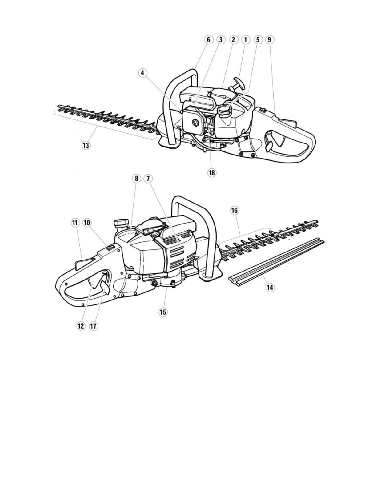
3. BESCHREIBUNG DER MASCHINENTEILE
BAUTEILE Fig.1
1) Griff des Starterseils
2) Starter
3) Chokehebel
4) Zündkerzenkappe
5) Tankverschluss
6) Vorderer Griff mit Schutz
7) Motor
8) Kraftstoffstank
9) Hinterer Griff mit Drehsteuerung
10) Stopp-Schalter des Motors ON/OFF.
11) Gashebelsperre
12) Gashebel
13) Messer
14) Messerschutz
15) Getriebegehäuse
16) Stumpfe Verlängerung
17) Steuerung der Drehverriegelung des
hinteren Griffs
18) Benzinpumpe
4. MONTAGE
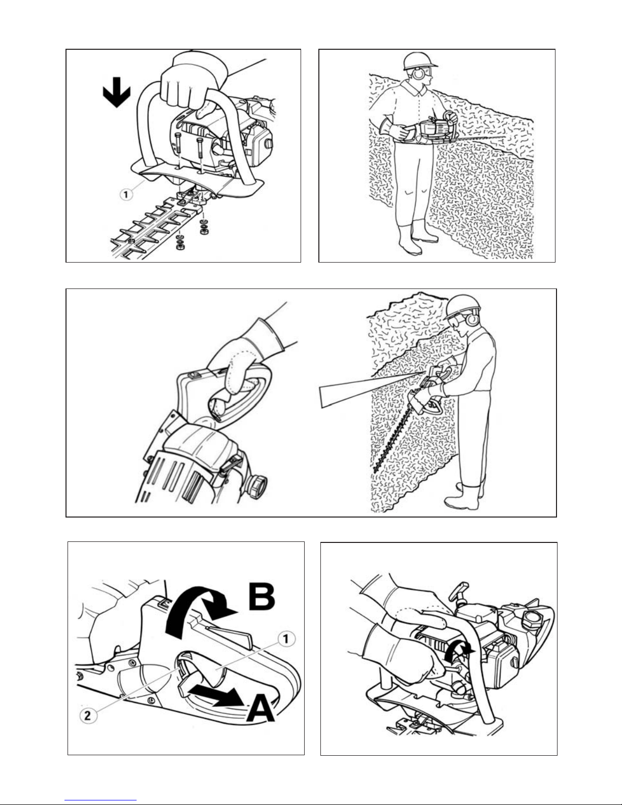
VORDERER GRIFF MIT SCHUTZ
1) Positionieren Sie den Griff (Teil 1) wie in
Abb. 2 dargestellt.
2) Schrauben Sie den Griff mit den 2 Schrau-
ben, Scheiben und Muttern (Abb. 2) fest.
Der Schutz dient zur Gewährleistung eines Sicherheitsabstands zwischen der
Hand des Bedieners und den Messern.
3) Vermeiden Sie Inbetriebsetzungund Gebrauch des nicht vollständig montierten Geräts.
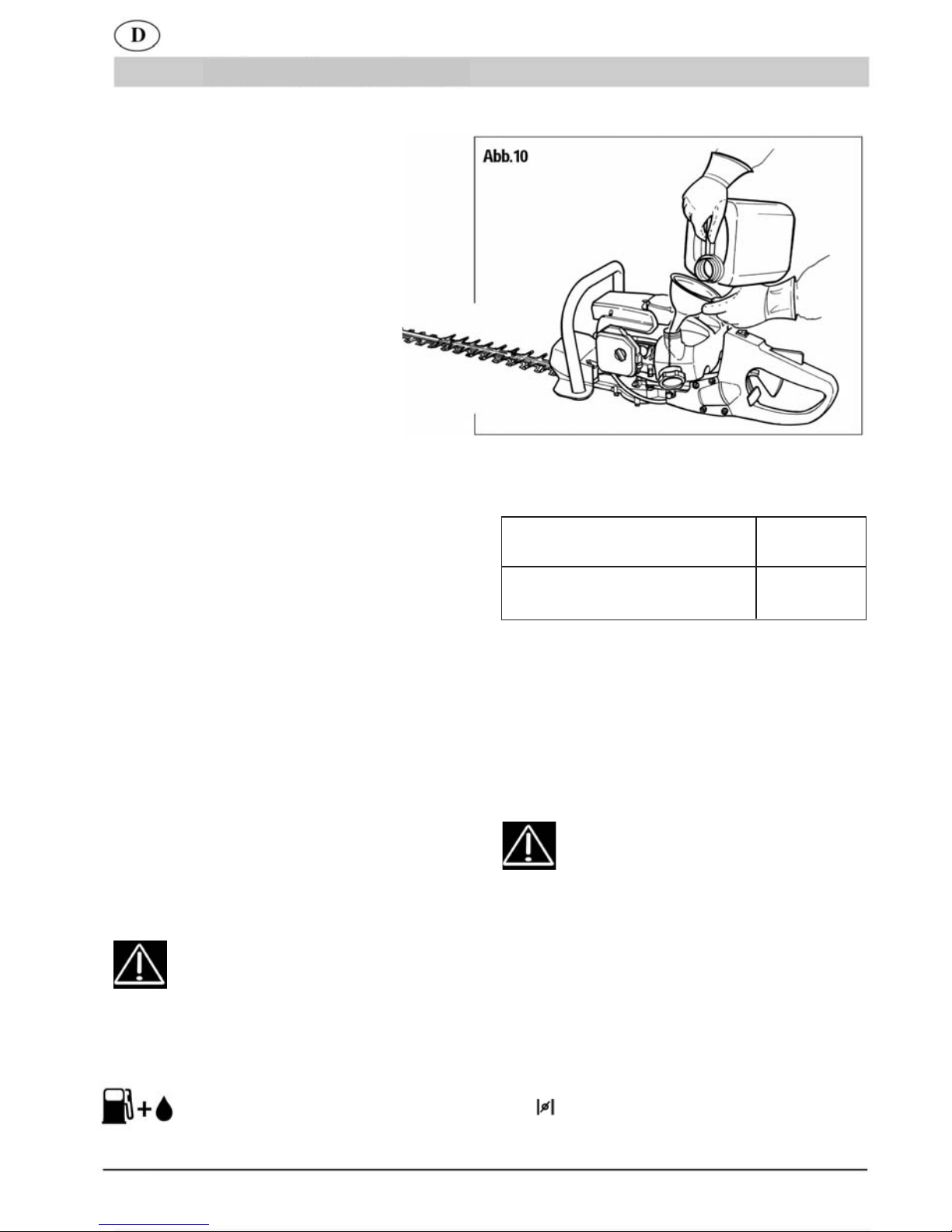
5. TANKEN VON KRAFTSTOFF
1) ACHTUNG! Das Gerät ist mit ei-
nem Zweitaktmotor ausgerüstet.
Der Motor muss mit einer Mischung aus Benzin und Öl für Zweitaktmotoren in folgenden
Verhältnissen versorgt werden.
Bei normalem Öl für
2-Takt-Motoren 1:40 (2,5%)
Bei sy
nthetischem Öl für
2-Takt-Motoren 1:40 (2,5%)
2) Mischen, indem man den Behälter vor jedem Auftanken gut schüttelt.
3) Mischen und Einfüllen des Kraftstoffs dürfen nur im Freien erfolgen (Abb. 10).
4) Den Kraftstoff in einem dafür geeigneten
und gut verschlossenen Behälter aufbewahren.
6. ANLAUF UND STOPP
ACHTUNG! Die im vorstehenden
Kapitel 2. WESENTLICHE SICHERHEITSVORKEHRUNGEN stehenden Hinweise sind strengstens zu
beachten.
ANLAUF BEI KALTEM MOTOR
1) Legen Sie die Heckenschere auf eine sta-
bile Auflage.
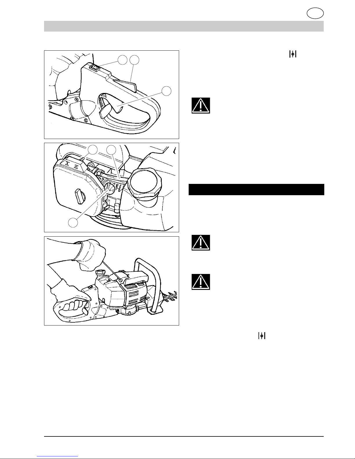
2) Den Stoppschalter (Abb. 11 Teil 1) auf die
Position „ON“ drücken.
3) Stellen Sie den Choke oberhalb der Luft-
filterabdeckung
(Abb. 12 Teil 1) in die Posi-
tion .
4) Die Benzinpumpe (Abb. 12 Teil 2) wiederholt
Gebrauchsanweisung
DE-3
Page 9
Gebrauchsanweisung
D
Abb.12
1 2
1
2
3
Abb.11
3
8) Stellen Sie den Lufthebel zurück (Abb. 12
Teil 1).
9) Ziehen Sie am Starterseil (Abb. 13), bis
der Motor startet.
ACHTUNG - GEFAHR !! Der Motor startet und bleibt beschleunigt; die Messer
sind also in Bewegung.
Lassen Sie den Motor bei gedrücktem Gas hebel einige Sekunden laufen.
10) Lassen Sie den Gashebel los. Der Motor geht
dadurch in Leerlauf, und die Messer bleiben stehen.
MOTOR-STOPP
1) Zum Stoppen des Motors ist der Schalter (Abb.
1 1 T eil 1) in die Position „OFF“ zu stellen.
Abb.13
è
tief drücken, bis der Kraftstoff über den zweiten transparenten Schlauch in den Behälter
zurückkehrt (Abb. 12 Teil 3).
5) Nehmen Sie den hinteren Griff in die linke Hand
und drücken Sie mit der Handfläche gegen die
Gasverriegelung (Abb. 11 Teil 2). Auf diese
Weise wird die Bewegung des Gaszugs
freigegeben (Abb.11 Teil 3).
6) Den Gashebel ganz drücken.
7) Das Starterseil (Abb. 13) bis zu 3 Mal
vollständig ziehen.
ACHTUNG! Machen Sie sich mit der
Bedienung des Stopp-Schalters vertraut,
um im Notfall schnell reagieren zu können.
ACHTUNG! Die Messer bewegen sich
nach dem Loslassen des Gashebels
noch für eine bestimmte Zeit weiter.
ANLAUF MIT WARMEM MOT OR
Gehen Sie wie beim Kaltstart vor, jedoch mit dem
Choke in der Position .
7. ANWENDUNG
Halten Sie das Gerät stets mit beiden Händen
fest. Arbeiten Sie mit voll gedrücktem Gas-
hebel.
SCHNEIDEN DES OBEREN HECKENTEILS
A) Halten Sie das Gerät in horizontaler Position (Abb. 3).
DE-4
Page 10
D
Gebrauchsanweisung
B) Der hintere Griff muss in vertikaler Position sein.
C) Arbeiten Sie aus Sicherheitsgründen nicht mit
dem Gerät über Schulterhöhe.
SCHNEIDEN DER SEITENTEILE DER HECKE
A) Für den vertikalen Schnitt richten Sie den hinte-
ren Griff für eine einfache und ergonomische Haltung von Hand und Arm aus. Halten Sie den vorderen Griff am Seitenteil (siehe Abb. 4 )
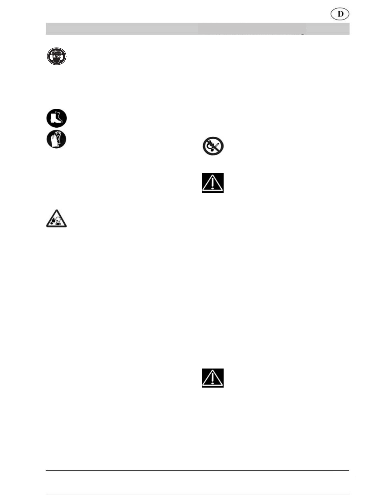
AUSRICHTUNG DES HINTEREN GRIFFS
B) Änderung der Neigung des hinteren Griffs:
1) Lassen Sie den Gashebel los (Abb. 5 T eil 1)
2) Ziehen Sie die Steuerung der Drehverriegelung
(Abb. 5 siehe Pfeil A). Drehen Sie den Griff (Abb. 5
siehe Pfeil B) bis zur gewünschten Neigung.
3) Lassen Sie die Steuerung der Verrieglung
wieder los.
4) Überprüfen Sie, ob die Griffdrehung blockiert ist.
5) Eine Schutzvorrichtung ermöglicht die
Aktivierung der Griffverriegelung (Abb.5
Teil 2) nur bei losgelassenem Gashebel.
Übermäßige Verkrustungen können bedingt sein
durch: - Der Ölanteil im Kraftstoff ist zu hoch bzw.
die Ölqualität ist nicht optimal.
- Luftfilter teilweise verstopft.
2) Die Kerze mit der Hand komplett ins Gewinde
einschrauben, um Schäden am Kerzensitz zu vermeiden; der entsprechende Schlüssel ist nur zum
Festziehen (Abb. 6) zu verwenden.
3) Führen Sie niemals Reparaturen am Gerät selbst
durch (wenn Sie dafür nicht qualifiziert sind). Wenden Sie sich hierzu an eine Kundendienststelle.
4) GETRIEBEGEHÄUSE (Abb. 8)
Füllen Sie alle 40 Betriebsstunden Fett für das Getriebe über den vorgesehenen Schmiernippel (Abb.
8 Teil 1) nach (handelsübliches Getriebefett).
GEFAHR!! Zum Erhalt der ursprüng
lichen Gerätesicherheit sollten niemals Veränderungen am Gerät vorgenommen
werden.
Verwenden Sie im Reparaturfall ausschließlich Originalersatzteile.
LUFTFILTER
8. W ARTUNG UND REPARATUR
GEFAHR!! Führen Sie niemals ir-
gendwelche Kontroll-, Wartungsoder Reparaturarbeiten bei laufendem Motor
durch.
KERZE
Mindestens einmal jährlich oder bei Störungen während des Startens ist der Zustand der Zündkerze
zu überprüfen. Abwarten, bis der Motor kalt ist.
.
1) Die Zündkerzenkappe abziehen und die Kerze mit * Baugruppe: Filter inkl. Luftfiltergehäuse
dem mitgelieferten Schlüssel abschrauben (Abb. 6).
Bei übermäßigen V erkrustungen und beachtlichem
Verschleiß der Elektroden ist die Kerze mit einer
gleichwertigen zu ersetzen (Abb. 7).
Reinigen Sie regelmäßig den Luftfilter (mindestens
alle 20 Stunden); häufiger, wenn Sie in staubiger
Umgebung arbeiten.
1) Die Flügelschraube des Deckels abschrauben
(Abb. 9).
2) Waschen Sie den Filter mit Benzin aus.
3) Den Filter trocknen lassen, bevor er wieder
platziert wird (Abb. 9).
Ein beschädigter Filter* muss ersetzt werden,
um die Lebensdauer des Motors nicht zu ver-
kürzen.
MOTOR-STOPP
DE-5
Page 11

MINDESTDREHZAHL DES MOTORS
- Vergewissern Sie sich bei jedem Gebrauch, dass die Schneidvorrichtung
im Leerlauf nicht in Bewegung ist.
- Sollte sie sich bewegen, wenden Sie sich
an eine Kundendienststelle für eine Korrigierung der Einstellung.
KONTROLLE DER SCHRAUBEN, FESTEN
UND BEWEGLICHEN TEILE
- Vergewissern Sie sich vor jedem Gebrauch,
dass keine Schrauben oder sonstigen Teile
locker bzw. beschädigt sind und keine Risse oder Abnutzungserscheinungen auf den
Messern sichtbar sind.
- Lassen Sie beschädigte Teile vor dem Gebrauch des Geräts von einem autorisierten
Kundendienst austauschen.
REINIGUNG, TRANSPORT UND LAGERUNG
- Leeren Sie für den Transport oder bei längerem Nichtgebrauch des Geräts den Kraftstofftank.
- Keine aggressiven Reinigungsmittel verwenden.
- Das Gerät ist auf einer trockenen und sicheren, Kindern unzugänglichen Stelle zu lagern.
- Stecken Sie zu Transport- und Lagerzwecken
den mitgelieferten Schutz auf die Messer.
ENTSORGUNG UND UMWELTSCHUTZ
Reste von 2-Taktmischung niemals in den Abfluss bzw. die Kanalisation oder ins Erdreich
schütten, sondern umweltgerecht entsorgen,
z.B. an einer Entsorgungsstelle.
Wenn Ihr Gerät eines Tages unbrauchbar
wird oder Sie es nicht mehr benötigen,
geben Sie das Gerät bitte auf keinen Fall
in den Hausmüll, sondern entsorgen Sie
es umweltgerecht. Entleeren Sie den Benzintank sorgfältig und geben Sie die Reste
an eine Sammelstelle. Geben Sie das Gerät
bitte ebenfalls in einer Verwertungsstelle ab.
Kunststoff- und Metallteile können hier getrennt und der Wiederverwertung zugeführt
werden. Auskunft hierzu erhalten Sie auch
in Ihrer Gemeinde- oder Stadtverwaltung.
Notizen:
TECHNISCHE DATEN BHS 60
Gebrauchsanweisung
Gewicht 6,0 kg
(ohne Kraftstoff)
Tankinhalt 600 cm
3
Motorhubraum 25,4 cm
3
Höchstleistung 0,75 kW
Max. Drehzahl <8.300 min
-1
Max. Messerfrequenz 2.000 min
-1
Leerlaufdrehzahl <3.000 min
-1
Schalldruckpegel 98 dB(A)
L
pA
nach (EN ISO 10517) K 3,0 dB(A)
Schallleistungspegel 110 dB(A)
LWA nach (EN ISO 10517)
Max. Vibrationspegel 11,0 m/s
2
vorderer Griff (EN ISO 10517) K 1,5 m/s²
DE-6
Page 12

1. FÉLICITATIONS
Cher client,
Nous vous félicitons d’avoir choisi
un de nos produits pour le jardin.
Le TAILLE-HAIE a été conçue en
tenant compte des normes de sécurité en vigueurpour protéger le
consommateur.
Ce manuel décrit et illustre
les différentes opérations de montage et
d’utilisation, ainsi
que les interventions d’entretien nécessaires pour
maintenir leparfait fonctionnement
de votre TAILLE-HAIE.
POUR FACILITER LA LECTUR
Les illustrations correspondant au
montage et à la description de la
machine se trouvent au début duprésent manuel.
Consulter ces pages pendant la
lecture des instructions de montage
et d’utilisation.
Si votre TAILLE-HAIE a besoin d’as-
sistance ou deréparation, veuillez
vous adresser à notre revendeur ou
à un centre d’assistance agréé.
2. PRECAUTIONS FONDAMENTALES DE
SECURITE
AVIS :
A1 - L’utilisation du TAILLE-HAIE
peut causer de sérieux dommages
aux personnes, il est donc demandé de respecter les consignes de
sécurité suivantes :
A2 – Toute personne qui utilise ou
met en marche le TAILLE-HAIE
doit toutd’abord lire attentivement
le manuel d’utilisation et d’entre-
tien, et se familiariser complètement avec les commandes pour un
usage correct de l’appareil.
A2.1 - Garder ce manuel pour le
consulter
à l’avenir.
A3 – Interdire l’utilisation du TAILLE-
HAIE aux enfants et aux personnes
n’ayant pas pleinement connaissancedes présentes instructions.
DANGER :
A4 – Ne pas mettre en marche et
ne pas utiliser l’appareil à proximité
de personnes (surtout des enfants)
et d’animaux.
Pendant le fonctionnement, il est
conseillé de maintenir une distance
minimale de 10 m entre la machine
et d’autres personnes.
A5 – La plus grande attention est
recommandée quant à de possibles
dangers qui ne peuvent être entendus àcause du bruit de l’appareil.
A6 – Éliminer tout danger, câbles,
câbles électriques de la zone de
travail.
A7 - L’opérateur est responsable
en cas d’accidents ou de risques
auxquelles despersonnes ou des
objets sont soumis.
UTILISATION :
B1 - N’utiliser le TAILLE-HAIE que-
pour tailler les haies, les arbrisseaux etles buissons.
Ne pas utiliser l’appareil pour
d’autres objectifs.
B2 – Porter des vêtements et un
équipement de sécurité adaptés à
l’utilisation du TAILLE-HAIE.
Pendant l’utilisation mettre des
vêtements collants et éviter des
vêtements amples. Ne pas porter
d’objets pouvant se prendre dans
les parties en mouvement.
FR-1
NORMES GENERALES
F
MANUEL D‘INSTRUCTION
Page 13

B3 - Mettre des lunettes de protection ou une visière homologuées.
B3.1 - Mettre un protège-oreilles
pour les bruits, homologué.
B3.2 - Mettre le casque de protection sides objets risquent de tomber.
B4 - Mettre des chaussures robustesavec des semelles anti-dérapage.
B5 - Mettre des gants robustes.
B6 – L’utilisateur du TAILLE-HAIE
doitêtre en bonne forme. NE PAS
UTILISER l’appareil en cas de fa-
tigue, de malaise ou sous l’effet de
l’alcool et de drogues.
B7 - ATTENTION ! Les gaz
d’échappement sont toxiques et asphyxiants; une fois inspirés, ils peuvent être mortels. Le moteur ne doit
jamais fonctionner dans un endroit
fermé et peu ventilé.
B8 - L’utilisation prolongée de l’appareil peut provoquer des troubles
de lacirculation sanguine des mains
(maladie des doigts blancs) provoqués parles vibrations.
Des facteurs qui exercent un impact sur la manifestation peuvent
être les suivants.
- Prédisposition personnelle de
l’opérateur à une mauvaise circulation sanguine dans les mains.
- Utilisation de l’appareil à de basses températures (nous conseillons
donc des gants chauds).
- De longues périodes d’utilisation
sans interruption (nous conseillons
une utilisation à intervalles).
- En cas de fourmillement et engourdissement, nous conseillons
de s’adresser à un médecin.
B8.1 - Prendre toujours l’appareil
avecles deux mains.
Se mettre dans une position stable
etsûre sur les deux jambes. Ne pas
sedéséquilibrer. Ne pas opérer sur
deséchelles instables. Pour tailler
les haies hautes, préférer un échafaudage stable.
B9 - ATTENTION ! L
’essence et ses
vapeurs sont très inflammables.
RISQUES DE BRULURES ET
D’INCENDIE.
B9.1 - Arrêter le moteur avant le
ravitaillement.
B9.2 - Ne pas fumer pendant le
ravitaillement de carburant.
B9.3 - Sécher le carburant éventuellement renversé. Mettre en
marche le moteur loin du lieu de
ravitaillement.
B9.4 - S’assurer que le bouchon
duréservoir est bien serré.
Faire attention à toute perte de
carburant.
B10 – DISPOSITIFS DE SECURITE
B10.1 – Le BLOCAGE DE LA
COMMANDE DE L’ACCELERATEUR (voirfig.1 pièce 17) empêche
l’actionnement accidentel du levier
de l’accélérateur.
B10.2 - INTERRUPTEUR (ON/OFF)
d’arrêt du moteur (fig. 1 pièce 10).
DANGER ! Attention : le dispositif
de coupe continue à tourner pour
quelques instants même après l’actionnement de l’interrupteur en position «OFF».
FR-2
F
MANUEL D‘INSTRUCTION
Page 14

Fig.10
Le moteur doit être alimenté par un mélange d’essence et huile pour des moteurs à 2
temps, dans les pourcentages suivants :
Avec huile normale pour moteur
à 2 temps 1:40 (2,5%)
Avec huile à base synthétique
pour moteur à 2 temps 1:40 (2,5%)
2) Bien mélanger et agiter le conteneur avant
chaque ravitaillement.
3) Préparer le mélange de carburant et effectuer le ravitaillement uniquement en plein
air (fig. 10).
4) Garder le carburant dans un conteneur
spécial prévu à cet effet et avec le bouchon
bien serré.
6. DEMARRAGE ET ARRET
ATTENTION ! Respecter soigneusement les avis du Chap.2 précédent PRECAUTIONS FONDAMENTALES DE SECURITE.
DEMARRAGE A MOTEUR FROID
1) Poser le Taille-haie sur une surface stable.
2) Presser l’interrupteur d’arrêt (fig. 11 pièce
1) en position «ON».
3. DESCRIPTION PARTIES MACHINE
DESCRIPTION Fig. 1
Poignée du câble de démarrage
Démarreur
Levier d’air (starter)
Capuchon de la bougie
Bouchon réservoir carburant
Poignée avant avec protection
Moteur à explosion
Réservoir carburant
Poignée arrière orientable aveccommandes
Interrupteur d’arrêt du moteur ON/OFF.
Blocage commande accélérateur
Levier de l’accélérateur
Lames de coupe
Gaine de protection des lames
Boîte d’engrenages
Extension non affûtée
Commande du blocage de la rotationde
la poignée arrière
Pompe à carburant
4. MONTAGE
POIGNEE AVANT AVEC PROTECTION
1) Positionner la poignée (pièce 1) comme
illustréen fig. 2.
2) Bloquer avec les 2 vis, les rondelles et les
écrous(fig. 2).
La protection a pour fonction d’assurer
unedistance de sécurité entre la main de
l’opérateur et les lames.
3) Ne pas mettre en marche et ne
pasutiliser l’appareil s’il n’est pas
complètement monté.
5. RAVITAILLEMENT CARBURANT
1) ATTENTION ! L’appareil est doté
demoteur à explosion à 2 temps.
1)
2)
3)
4)
5)
6)
7)
8)
9)
10)
11)
12)
13)
14)
15)
16)
17)
18)
FR-3
F
MANUEL D‘INSTRUCTION
Page 15

MANUEL D'INSTRUCTION
F
3) Mettre le starter situé au-dessus du couvercle du
filtre à air (fig. 12 pièce 1) en position .
4) Presser à fond plusieurs fois le bulbe d’amorçage (fig. 12 pièce 2) jusqu’à ce que le carburant
retourne dans le réservoir à travers le deuxième
tube transparent (fig. 12 pièce 3).
5) Saisir la poignée arrière avec la main gauche en
pressant avec la paume le blocage de l’accélérateur (fig. 11 pièce .2), pour libérer ainsi le mouvement du levier de l’accélérateur (fig. 1 1 pièce 3).
6) Presser à fond le levier de l’accélérateur.
7) Tirer à fond jusqu’à 3 fois la poignée du
câble de démarrage (fig.13).
8) Déplacer en arrière le starter dans la position
(fig. 12 pièce 1).
9) Tirer le lanceur (fig. 13) jusqu’au démarrage du
moteur.
A TTENTION – DANGER !! Le moteur
se met en marche et reste accéléré, les
lames sont donc en mouvement.
Laisser fonctionner le moteur avec le levier pressé
pendant quelques secondes.
10) Relâcher le levier de l’accélérateur. Le moteur
reste ainsi en marche au ralenti et les lames s’arrêtent.
Fig.12
1 2
Fig.11
3
1
3
2
Fig.13
è
ARRET MOTEUR
1) Pour arrêter le moteur mettre l’interrupteur (fig.
1 1 pièce 1) en position «OFF».
ATTENTION ! Se familiariser avec
l’actionnement de l’interrupteur d’arrêt afin
d’agir promptement en cas d’urgence.
A TTENTION ! Après avoir relâché le le
vier de l’accélérateur, les lames restent
en mouvement pendant un certain temps.
DEMARRAGE A MOTEUR CHAUD
Procéder comme pour le démarrage à froid, mais
avec le starter en position .
7. UTILISATION
Il faut toujours saisir l’appareil avec les deux
mains. Opérer en pressant au maximum le levier de l’accélérateur.
FR-4
Page 16

F
MANUEL D'INSTRUCTION
TAILLE DE LA PARTIE SUPERIEURE DE LA
HAIE
A) T enir l’appareil en position horizontale (fig. 3).
B) La poignée arrière en position verticale.
C) Pour des motifs de sécurité, ne pas opérer avec
l’appareil au-dessus de la hauteur des épaules.
T AILLE DES P ARTIES LATERALES DE LA HAIE
A) Pour la taille verticale, orienter la poignée ar-
rière de manière à obtenir une position confortable
et ergonomique de la main et du bras. Tenir la
poignée avant pour la partie latérale (voir fig. 4 ).
ORIENT A TION DE LA POIGNEE ARRIERE
B) Pour changer l’inclinaison de la poignée arrière :
1) Relâcher le levier de l’accélérateur (fig. 5 pièce 1)
2) Tirer la commande du blocage de la rotation (fig.
5 voir flèche A ). Tourner la poignée (fig. 5 voir
flèche B), jusqu’à l’inclinaison désirée.
3) Relâcher la commande du blocage.
4) Vérifier que la rotation de la poignée est blo-
quée.
5) Un dispositif de sécurité permet d’ac-
tionner la commande du blocage de la
poignée (fig. 5 pièce 2) uniquement quand
le levier de l’accélérateur est relâché.
8. ENTRETIEN ET REP ARA TION
DANGER !! N’effectuer aucun con
trôle, entretien et réparation avec le
moteur en marche.
clé fournie (fig. 6).
En cas d’incrustations et d’usure excessive des électrodes, remplacer la bougie par une autre de type
équivalent (fig. 7).
Un excès d’incrustations peut être provoqué par
- Pourcentage d’huile excessif dans le carburant et/
ou qualité de l’huile non appropriée.
- Obstruction partielle du filtre à air .
2) Visser manuellement la bougie à fond pour ne
pas endommager son logement. Utiliser la clé spéciale seulement pour le serrage (fig.6).
3) Ne pas réparer l’appareil, si vous n’êtes pas
qualifié pour le faire. S’adresser à un centre d’assistance qualifié.
4) BOITE D’ENGRENAGES (fig. 8)
T outes les 40 heures de fonctionnement, ajouter de
la graisse pour engrenages, à travers le graisseur
prévu à cet effet (fig. 8 pièce 1).
DANGER !! Afin de conserver les con
ditions de sécurité d’origine, ne pas
apporter de modifications à l’appareil.
En cas de réparations, utiliser exclusivement
des pièces de rechange d’origine.
FILTRE A AIR
Nettoyer périodiquement le filtre à air (au moins toutes les 20 heures) ; plus souvent en cas de fonctionnement dans des zones poussiéreuses.
1) Dévisser l’écrou à ailettes du couvercle (fig. 9).
2) Laver avec de l’essence.
3) Laisser sécher le filtre avant son remontage (fig. 9).
Remplacer un filtre endommagé pour ne pas
compromettre la durée du moteur.
BOUGIE
Au moins une fois par an ou en cas de difficulté
dans le démarrage, vérifier l’état de la bougie d’allumage. Attendre le refroidissement du moteur avant
l’opération.
1) Extraire le capuchon et dévisser la bougie par la
FR-5
FIL TRE DU TUY AU D’ASPIRA TION DU CARBURANT
Remplacer une fois par an le filtre après son extraction par un crochet à travers l’ouverture de ravitaillement du réservoir.
Page 17

REGIME DE RALENTI DU MOTEUR
-Vérifier à chaque utilisation que le
dispositif de coupe n’est pas en mouvement au ralenti.
- S’il a tendance à se mettre en mouvement,
s’adresser à un centre d’assistance pour
l’intervention de réglage.
VERIFICATION DES VIS, DES PARTIES
FIXESET EN MOUVEMENT
- Avant utilisation, contrôler qu’il n’y a pas de
vis oude parties desserrées ou abîmées, et
que les lames de coupe ne présentent pas
de criques ou une grande usure.
- Faire remplacer les parties endommagées
par un centre d’assistance agréé avant d’utiliser l’appareil.
NETTOYAGE, TRANSPORT ET REMISAGE
- En cas de transport ou d’inactivité prolongée, vider le réservoir du carburant.
- Ne pas nettoyer avec des liquides agressifs.
- Garder l’appareil dans un milieu sec et sûr,
horsde portée des enfants.
- En cas de transport ou de remisage, couvrir
les lames avec la gaine de protection livrée.
RECYCLAGE ET PROTECTION DE L’ENVIRONNEMENT
Ne jamais verser les restes d’huile de chaîne
ou le mélange pour moteurs à 2 temps dans les
égouts, les canalisations ou sur le sol, mais les
recycler en respectant les principes de protection
de l’environnement, par exemple en les portant
à un centre de traitement des déchets.
Au cas où votre appareil devenait un jour
inutilisable ou si vous n’
en aviez plus l’usage,
ne jetez en aucun cas l’appareil avec les déchets ménagers, mais veillez à un recyclage
conforme aux principes écologiques. Videz soi-
gneusement le réservoir à huile et à essence
et allez déposer les restes dans un centre de
traitement des déchets. Allez déposer l’appa-
reil lui aussi dans un centre de recyclage. Les
éléments en matière synthétique et en métal
seront séparés et réutilisés. Votre commune
ou l’administration urbaine vous fourniront tous
les renseignements à ce sujet.
Note:
DONNEES TECHNIQUES BHS 60
MANUEL D‘INSTRUCTION
Poids 6,0 kg
(sans carburant)
Capacité réservoir 600 cm
3
Cylindrée moteur 25,4 cm
3
Puissance maximum 0,75 kW
Régime maximum du moteur <8.300min
-
1
Fréquence maximale lames 2.000 min
-
1
Régime minimum <3.000min
-
1
Niveau de pression acoustique 98dB(A)
L
pA
selon (EN ISO 10517) K 3,0 dB(A)
Niveau de puissance acoustique 110 dB(A)
LWA selon (EN ISO 10517)
Niveau vibrations max 11,0 m/s
2
poignée avant (EN ISO 10517) K 1,5 m/s²
F
FR-6
Page 18

1. CONGRATULAZIONI
Gentile cliente, vogliamo congratularci con
Lei peraver scelto un nostro prodotto per il
giardino.
Il Vostro TAGLIASIEPI è stato costruito, te-
nendo conto delle norme di sicurezza vigenti
atutela del consumatore.
In questo manuale sono descritte ed illustrate levarie operazioni di montaggio, di uso
ed interventidi manutenzione, necessari per
mantenere in perfetta efficienza il Vostro TA-
GLIASIEPI.
PER FACILITARE LA LETTURA
Le illustrazioni corrispondenti al montaggio
e alla descrizione della macchina si trovano,
all‘inizio del presente fascicolo.
Consultare queste pagine durante la lettura
delle istruzioni di montaggio e di utilizzo.
Nel caso il Vostro TAGLIASIEPI necessitasse di assistenza o riparazione, Vi preghiamo
di rivolgervi al nostro rivenditore o ad un centro assistenza autorizzato.
2. PRECAUZIONI FONDAMENTALIDI
SICUREZZA
A
VVERTENZE:
A1 - L‘utilizzo del TAGLIASIEPI può
provocare seri danni alle persone,
èpertanto richiesto il rispetto delle
seguenti norme di sicurezza:
A2 - Chiunque utilizzi o comunque
metta in moto il TAGLIASIEPI deve
primaleggere attentamente il manuale di istruzioni e manutenzione
e familiarizzare completamente con
i comandi per unuso corretto dell‘apparecchio.
A2.1 - Conservare il presente manuale per consultazioni future.
A3 - Non permettere l‘uso del TAGLIASIEPI ai bambini ed a perso-
ne che non siano completamente a
conoscenza delle presenti istruzioni.
PERICOLO:
A4 - Non mettere in moto e non uti-
lizzare l‘apparecchio in prossimità
di persone (specialmente bambini)
ed animali.
Durante il funzionamento si raccomanda una distanza minima di 10 m
tra la macchina ed altre persone.
A5 - Si raccomanda la massima attenzione verso possibili
pericoli che
non possano essere uditi a causa
del rumore dell‘apparecchio.
A6 - Eliminare qualsiasi pericolo,
cavi, cavi elettrici
dalla zona di la-
voro.
A7 - L‘operatore è responsabile in
casodi incidenti o pericoli occorsi
ad
altre persone od alle loro cose.
UTILIZZO:
B1 - Impiegare il TAGLIASIEPI so-
lamente per tagliare siepi, arboscelli
ecespugli.
Non impiegare l‘apparecchio per
scopi diversi.
B2 - Indossare un‘abbigliamento ed
un equipaggiamento di sicurezza
adatto all‘utilizzo del TAGLIASIEPI.
Durante l‘utilizzo indossare abiti
aderenti e
non sciolti. Non indossa-
re oggetti che possano
impigliarsi
nelle partiin movimento.
B3 - Indossare
occhiali di protezio-
ne ovisiera omologati.
B3.1 - Indossare paraorecchi di protezione per il rumore, omologati.
IT-1
NORME GENERALI
I
MANUALE ISTRUZIONI
Page 19

B3.2 - Indossare il casco di protezionein caso di rischio di caduta di
oggetti.
B4 - Calzare scarpe robuste con
suolenon sdrucciolevoli.
B5 - Indossare guanti robusti.
B6 - Chi utilizza il TAGLIASIEPI
deve essere in buona forma. NON
UTILIZZARE l‘apparecchio in condi-
zioni distanchezza, di malessere o
sotto l‘effetto di alcool e di droghe.
B7 - ATTENZIONE! I gas di scaricosono velenosi ed asfissianti. Se
inspirati possono quindi essere anche mortali. Non fare funzionare il
motore in luogo chiuso o scarsamente ventilato.
B8 - L‘utilizzo prolungato dell‘apparecchio può causare disturbi di circolazione sanguigna alle mani (malattia delledita bianche) attribuibili
alle vibrazioni. Fattori che influiscono sulla manifestazione dei disturbi
possono essere:
- Predisposizione personale dell‘operatore ad una scarsa irrorazione sanguigna delle mani.
- Utilizzo dell‘apparecchio a basse
temperature (si consigliano pertanto guanti caldi).
- Lunghi tempi di utilizzo senza
interruzioni (si consiglia un utilizzo
ad intervalli).
- In caso di manifestazione di formicolioe intorpidimento si raccomanda di consultare un medico.
B8.1 -Sostenere l‘apparecchio sempre con ambedue le mani.
Assumere una posizione stabile e
sicura su entrambe le gambe. Non
sbilanciarsi. Non operare su scale
instabili. Per tagliare siepi alte, preferire una stabile impalcatura.
B9 - ATTENZIONE! la benzina ei
suoi vapori sono estremamente infiammabili.
PERICOLO DI USTIONI ED INCENDIO.
B9.1 - Arrestare il motore
prima del
rifornimento.
B9.2 - Non fumare durante il rifornimento di carburante.
B9.3 -Asciugare il carburante eventualmente rovesciato. Mettere in
moto il motore lontano dal luogo di
rifornimento.
B9.4 - Assicurarsi che il tappo del
serbatoio sia ben serrato. Fare attenzione ad eventuali perdite.
B10 - DISPOSITIVI DI SICUREZZA
B10.1 - Il BLOCCO DEL COMANDO-
DELL‘ACCELERATORE (vedi fig.1
part.17) impedisce l‘azionamento accidentale della leva dell‘acceleratore.
B10.2 -INTERRUTTORE (ON/OFF)
di arresto del motore (fig.1 part.10).
PERICOLO! Attenzione il dispositivo ditaglio continua a girare per un
certotempo anche dopo l‘azionamento dell‘interruttore sulla posizione „OFF“.
3. DESCRIZIONI PARTI MACCHINA
DESCRIZIONE (Fig.1)
Maniglia della fune di avviamento
Avviatore
Levetta dell‘aria
Cappuccio della candela
Tappo serbatoio carburante
Impugnatura anteriore con protezione
Motore a scoppio
Serbatoio carburante
Impugnatura posteriore con comandiorientabile
Interruttore di arresto del motore ON/
OFF.
Blocco del comando dell‘acceleratore
Leva dell‘acceleratore
1)
2)
3)
4)
5)
6)
7)
8)
9)
10)
11)
12)
IT-2
MANUALE ISTRUZIONI
I
Page 20

Lame di taglio
Guaina di protezione lame
Scatola ingranaggi
Estensione non affilata
Comando del fermo di rotazionedell‘impugnatura posteriore
Pompa del carburante
4. MONTAGGIO
IMPUGNATURA ANTERIORE CON PROTEZIONE
1) Posizionare come illustrato nella fig.2
l‘impugnatura (part.1).
2) Bloccare con le n°2 viti, rosette e dadi
(fig.2).
La protezione ha la funzione di assicurare unadistanza di sicurezza tra la mano
dell‘operatore e le lame.
3)
Non mettere in moto e non usarel‘apparecchio se non è completamente montato.
5. RIFORNIMENTO CARBURANTE
1) ATTENZIONE! L‘apparecchio è
equipaggiato di motore a scoppio
a 2 tempi.
Il motore deve essere alimentato con una
miscela dibenzina e olio per motori a 2 tempi, nelle seguenti percentuali.
Con olio normale per motore
2 tempi 1:30 (3,3%)
Con olio a base sintetica per
motore tempi 1:40 (2,5%)
2) Miscelare agitando abbondantemente il
contenitore prima di ogni rifornimento.
3) Preparare la miscela carburante e fare rifornimento solo all‘aperto (fig.10).
4) Conservare il carburante in un contenitore previsto per questo uso e con tappo ben
serrato.
13)
14)
15)
16)
17)
18)
6. AVVIAMENTO E ARRESTO
ATTENZIONE!
Osservare scrupolosamente gli avvertimenti contenuti
nel precedente Cap. 2 PRECAUZIONI FONDAMENTAL
I DI SICUREZZA.
AVVIAMENTO A MOTORE FREDDO
1) Appoggiare il Tagliasiepi su una superficie
stabile.
2) Premere l‘interruttore di arresto (fig. 11
part.1) sulla posizione „ON“.
3) Desplazar la palanca del aire situada encima de la tapa del filtroaire (fig.12 part.1) en
la posizione .
4) Pressare a fondo ripetutamente il bulbo
primer (fig.12 part.2) fino a quando il carburante ritorna nel serbatoio attraverso il se
-
condo tubetto trasparente (fig.12 part.3).
5) Afferrare l‘impugnatura posteriore
con la
mano sinistra premendo con il palmo il blocco acceleratore (fig.11 part.2), si libera in
questo modo il movimento dellaleva acceleratore (fig.1
1 part. 3).
6) Premere a fondo la leva dell‘acceleratore.
7) Tirare a fondo fino a
3 volte la maniglia
della funedi avviamento (fig.13)
IT-3
I
MANUALE ISTRUZIONI
Fig.10
Page 21

MANUALE ISTRUZIONI
I
Fig.12
Fig.11
1 2
3
1
2
3
Fig.13
10) Rilasciare la leva acceleratore. Il motore rima-
ne così in moto al regime minimo quindi le lame si
arrestano.
ARRESTO MOTORE
1) Per arrestare il motore, portare l'iterruttore (fig.1 1
part. 1) nella posizione "OFF".
ATTENZIONE! Prendere familiarità con
l'azionamento dell'interruttore di arresto in
modo di agire prontamente in caso di emergenza.
ATTENZIONE! Le lame continuano a muoversi per un certo tempo dopo il rilascio
della leva acceleratore.
A VVIAMENTO A MOTORE CALDO
Procedere come a motore freddo ma con la levetta
dell'aria spostata nella posizione .
è
8) Spostare indietro la levetta dell'aria del nella
posizione (fig.12 part.1).
9) Tirare la fune di avviamento (fig.13) fino alla
messa in moto del motore.
A TTENZIONE - PERICOLO !! Il motore si
avvia e rimane accelerato quindi le lame
sono in movimento.
Lasciare funzionare il motore a leva premuta per
alcuni secondi.
7. UTILIZZO
Impugnare sempre l'apparecchio con entrambe le mani. Operare premendo al massimo la
leva dell'acceleratore.
TAGLIO DELLA PARTE SUPERIORE DELLA
SIEPE
A) Tenere l'apparecchio in posizione orizzontale
(fig. 3).
B) L'impugnatura posteriore in posizione verticale.
C) Per motivi di sicurezza non operare con l'appa-
recchio al di sopra dell'altezza delle spalle.
TAGLIO DEI FIANCHI DELLA SIEPE
A) Per il taglio verticale, orientare l'impugnatura
posteriore per una facile ed ergonomica posizione
IT-4
Page 22

I
MANUALE ISTRUZIONI
della mano e del braccio. Tenere l'impugnatura
anteriore per la parte laterale (vedi fig. 4 )
ORIENTAMENTO DELL'IMPUGNATURA POSTERIORE
B) Per cambiare l'inclinazione dell'impugnatura
posteriore:
1) Rilasciare la leva dell'acceleratore (fig.5 part.1)
2) Tirare il comando del fermo della rotazione (fig.5
vedi freccia A). Ruotare l'impugnatura (fig.5 vedi
freccia B), fino all'inclinazione desiderata.
3) Rilasciare il comando del fermo.
4) V erificare che la rotazione dell'impugnatura sia
bloccata.
5) Un dispositivo di sicurezza permette di
azionare il comando del fermo impugnatu-
ra (fig.5 part.2) solo quando la leva del-
l'acceleratore è rilasciata.
qualità non appropriata dell'olio.
- Filtro aria parzialmente ostruito.
2) Avvitare la candela a mano fino a fondo filetto per
evitare danni alla sua sede. Usare l'apposita chiave
solo per il serraggio (fig.6).
3) Non effettuare riparazioni dell'apparecchio (se
non si è qualificati per farlo). Rivolgersi ad un centro di assistenza qualificato.
4) SCAT OLA INGRANAGGI (fig.8)
Ogni 40 ore di funzionamento aggiungere grasso
per ingranaggi, tramite l'apposito ingrassatore
(fig.8 part.1).
PERICOLO!! Al fine di conservare le
originali condizioni di sicurezza, non
effettuare modifiche all'apparecchio.
In caso di riparazioni utilizzare esclusivamente parti di ricambio originali.
8. MANUTENZIONE E RIPARAZIONE
PERICOLO!! Non effettuare alcun controllo, manutenzione e riparazione con
motore in moto.
CANDELA
Almeno una volta all'anno od in caso di difficoltà di
messa in moto, verificare lo stato della candela di
accensione. Attendere che il motore si raffreddi prima dell'operazione.
1) Sfilare il cappuccio e svitare la candela con la
chiave in dotazione (fig.6).
In caso di eccessive incrostazioni e notevole usura
degli elettrodi, sostituire la candela con una di tipo
equivalente (fig.7).
Un eccesso di incrostazioni può essere dovuta a:
- Eccessiva percentuale di olio nel carburante e/o
FILTRO ARIA
Pulire periodicamente il filtro aria (almeno ogni 20
ore); più frequentemente se si opera in aree polverose.
1) Svitare la vite a galletto del coperchio (fig.9).
2) Lavare con benzina.
3) Fare asciugare il filtro prima di riposizionarlo
(fig.9).
Sostituire il filtro se danneggiato per non compromettere la durata del motore.
FIL TRO PESCANTE DEL CARBURANTE
Sostituire una volta all'anno il filtro estraendolo con
un gancio attraverso l'apertura di rifornimento del
serbatoio.
REGIME MINIMO DEL MOTORE
- Verificare ad ogni utilizzo che al regime-
minimo il dispositivo di taglio non sia in mo-
vimento.
IT-5
Page 23

- Se tende a muoversi rivolgersi ad un centro
di assistenza per l‘intervento di regolazione.
VERIFICA VITI, PARTI FISSE ED IN MOVIMENTO
- Prima di ogni utilizzo controllare che non
ci siano viti o parti allentate o danneggiate e
che non ci siano cricche o notevoli usure nelle
lame di taglio.
- Fare sostituire ad un centro assistenza
autorizzatole le parti danneggiate prima di
utilizzare l‘apparecchio.
PULIZIA TRASPORTO E RIMESSAGGIO
- In caso di trasporto o di lunga inattività,
vuotare ilserbatoio del carburante.
- Non pulire con liquidi aggressivi.
- Conservare l‘apparecchio in luogo asciutto
e sicuro non accessibile ai bambini.
- In occasione di trasporto o rimessaggio
coprire lelame con l‘apposita guaina di protezione in dotazione.
SMALTIMENTO E PROTEZIONE DELL’AMBIENTE
Non scaricare i residui di olio per catena e/o
miscela negli scarichi, nelle fognature o nel
terreno, bensì smaltirli in modo ecologico, ad
esempio conferendoli in discarica.
Una volta divenuto inutilizzabile o non più
necessario l’attrezzo non potrà essere gettato in nessun caso nella spazzatura di casa,
ma dovrà essere smaltito in modo ecologico.
Svuotare accuratamente i serbatoi di olio e
benzina e conferire i residui di tali sostanze
alla raccolta differenziata. Anche l’attrezzo
dovrà essere consegnato ad un centro di
raccolta e recupero. I componenti di plastica
e metallo qui potranno essere separati e
destinati al riciclo. Informazioni al riguardo
sono disponibili anche presso gli enti pubblici
comunali e municipali.
Note:
DATI TECNICI BHS 60
MANUALE ISTRUZIONI
Peso
6,0 kg
(senza carburante)
Capacità serbatoio 600 cm
3
Cilindrata motore 25,4 cm
3
Potenza massima 0,75 kW
Regime massimo del motore <8.300min
-1
Frequenza massima lame 2.000 min
-1
Regime di minimo <3.000min
-1
Livello di pressione acustica 98 dB(A)
L
pA
secondo (EN ISO 10517) K 3,0 dB(A)
Livello di potenza acustica 110 dB(A)
LWA secondo (EN ISO 10517)
Livello vibrazioni max impug- 11,0 m/s
2
natura posteriore (EN ISO 10517) K 1,5 m/s²
I
IT-6
Page 24

1. CONGRATULATIONS
Dear Client,
May we congratulate you for having chosen
one ofour products for your garden.
Your HEDGETRIMMER has been manufactured in accordance with the current safety
regulations, which protect the consumer.
This manual describes and illustrates the
assembly, use and maintenance operations,
which are required in order to keep your
HEDGETRIMMER inperfect condition.
TO FACILITATE READING
The illustrations relating to the assembly and
machine description are to be found at the
beginning oft his booklet. Keep these pages
open while reading the assembly instructions.
Should your HEDGETRIMMER need servicing or repair, please contact your retailer or
an authorised service centre.
2. ESSENTIAL SAFETY PRECAU TIONS
PRECAUTIONS:
A1 - The use of your HEDGE TRIMMER can cause serious injury,
therefore the following safety instructions should be followed:
A2 - All users of the HEDGETRIMMER must first carefully read the
maintenance and operating manual
and familiarise themselves fully with
all controls for correct operation of
the machine.
A2.1 - Keep this manual for future
reference.
A3 - Do not let children and people
who have not fully read these instructions to use the HEDGETRIM-
MER.
DANGER:
A4 - Do not start up and do not use
the hedgecutter near people (specially children) and animals.
During operation, a minimum distance of 10 m between the machine
and other people should be kept.
A5 - Be aware of any possible dangers which cannot be heard due to
the noise produced by the machine.
A6 - Remove any dangers, cables
or electrical cables from the working area.
A7 - The operator is responsible for
any accidents or hazards that may
occur to other persons or their belongings.
OPERATION:
B1 - Only use the HEDGETRIMMER to cut hedges, bushes and
saplings. Do not use the machine
for other purposes.
B2 - Wear clothing and safety equipment suitable for HEDGETRIMMER
operation. During operation wear
close-fitting clothing and not loose
or baggy garments. Do not wear
objects which can get caught in the
moving parts
B3 - Wear approved protective goggles or visor.
B3.1 - Wear approved noise-damping earplugs.
B3.2 - Wear a safety helmet in areas where objects are likely to fall.
B4 - Wear sturdy shoes with nonslip soles.
B5 - Wear sturdy gloves
OPERATING MANUAL
GB-1
GENERAL REGULATIONS
GB
Page 25

OPERATING MANUAL
GB
B6 – HEDGETRIMMER users must be
in good physical condition. DO NOT
USE the machine if you feel tired, ill or
are under the influence of alcohol or
other drugs.
B7 - CAUTION! Exhaust fumes are
toxic and asphyxiating. If inhaled, these
fumes may even be lethal. Do not start
the engine in closed or poorly ventilate
environments.
B8 - Prolonged use of the machine may
hinder blood circulation to the hands
(Raynaud’s phenomenon) due to vibrations.
The following factors may pose a risk to
the operator’s health:
- Operator is predisposed to poor blood
circulation in the hands.
- The machine is used in cold weather
(warm gloves are strongly recommended).
- The machine is used non-stop for long
periods (we suggest using it at intervals).
- If you feel a tingling sensation or numb
in any way , please seek medical attention.
B8.1 - Always hold the machine with
both hands.
Stand in a safe and steady position on
both legs. Stay balanced. Do not use
on unstable ladders. T o cut tall hedges,
a stable scaffold is recommended.
B9 - CAUTION! Petrol and
its vapours are highly flammable.
BURNING AND FIRE HAZARDS.
B9.1 - Stop the engine before refuel-
ling.
B9.2 - Do not smoke while refuelling.
18) Fuel pump
3. DESCRIPTIONS OF MACHINE
PARTS
1) Starter grip
2) Starter
3) Chock lever
4) Spark plug cap
5) Fuel cap
6) Front handle with guard
7) Combustion engine
8) Fuel tank
9) Rear handle with adjustable controls
10) Engine cut-off switch ON/OFF .
11) Throttle trigger lock out
12) Throttle control lever
13) Cutting blades
14) Cutting blade sleeve
15) Gearbox
16) Blunt extension
17) Rear handle rotation lock control
B9.3 - Wipe off any fuel that may have
spilled. Start up the engine away from
the place where it was refuelled.
B9.4 - Make sure the tank cap is tightened properly.
Beware of any leaks.
B10 – SAFETY DEVICES
B10.1 – the THROTTLE LEVER
LOCK (see fig.1 part. 17) prevents the
accidental use of the throttle control lever.
B10.2 – the ENGINE CUT-OFF
SWITCH (ON/OFF) stops the engine
(fig. 1 part. 10).
DANGER! Caution! The cutting blade
continues to spin for a while even after
the power switch has been shut “OFF”.
Fig. 1 LEGEND
GB-2
Page 26

GB
OPERATING MANUAL
4. ASSEMBL Y
FRONT HANDLE WITH GUARD
1) Position the handle (part. 1.) as illustrated in fig-
ure 2.
2) Clamp with 2 screws, washers and nuts (fig. 2).
The guard is mounted to ensure a safe distance between the hand of the user and the
blade.
3) Do not start or use the machine if
it not fully assembled.
5. REFUELLING
1) CAUTION! The machine is equipped
with a two-stroke engine.
The engine must be supplied with a mixture of petrol and oil for two-stroke engines in the following
ratios.
With normal oil for two-stroke engines 1:30 (3,3%)
With synthetic oil for two-stroke engines 1:40 (2.5%)
2) Mix by stirring the container thoroughly before
refilling the tank.
3) Prepare fuel mixture and only refuel outdoors
(fig. 10).
4) Store the fuel in a container set aside for this
purpose and with tightly sealed cap.
6. ST ARTING AND STOPPING
CAUTION! Strictly heed the warnings
outlined in the chapter 2 above ti-
tled ESSENTIAL SAFETY PRECAUTIONS.
Fig.10
3) Lift the choke lever located above the air filter
cover (fig.12 part.1) and place it in position .
4) Repeatedly press the primer bulb (fig. 12 part. 2)
down until the fuel returns to the tank through the
second transparent hose (fig.12 part. 3).
5) Grip the rear control with the left hand using the
palm of the hand to press the throttle lock (fig.1 1 part.
2), which allows free movement of the throttle control
lever (fig.1 1 part. 3).
6) Press the throttle control lever right down.
7) Pull the starter grip completely as many as 3 times
(fig. 13).
8) Push the choke lever down (fig.12 part.1).
9) Pull the starter cable (fig.13) until the engine starts.
CAUTION - DANGER !! The engine
starts and accelerates causing the blades
to move.
Let the engine run with the lever pressed for a few
seconds.
10) Release the throttle lever. The engine will return
to idle and the blades will stop moving.
COLD ENGINE ST ARTUP
1) Place the hedgecutter on a stable surface.
2) Press the stop button (fig. 1 1 part. 1) to the “ON”
position.
GB-3
Page 27

OPERATING MANUAL
GB
Fig.12
1 2
1
2
3
Fig.11
3
1) T o stop the engine, shut the power switch (fig. 1 1
part. 1) “OFF”.
CAUTION! Familiarise yourself with the
operation of the throttle lock in order to act
quickly in case of an emergency .
CAUTION! The blades continue to move
for a while after the throttle lever is released.
W ARM ENGINE STARTUP
Follow the instruction given for cold engine startup,
but with the choke lever in position .
7. OPERA TION
STOP ENGINE
è
Fig.13
Always grip the machine with both hands. Operate by opening the throttle lever to maximum.
CUTTING THE TOP OF THE HEDGE
A) Keep the machine in a horizontal position (fig. 3).
B) The rear handle in a vertical position.
C) For safety reasons, do not use the machine above
shoulder height.
CUTTING THE SIDES OF THE HEDGE
A) For a vertical cut, move the rear handle into a
comfortable position for the hand and arm. Hold the
front handle with the side grip (see fig. 4)
POSITION OF THE REAR HANDLE
B) T o change the inclination of the rear handle:
1) Release the throttle lever (fig.5 part.1)
2) Engage the rotation lock control (fig. 5 see arrow
A). Rotate the handle (fig. 5 see arrow B), until the
required angle is obtained.
GB-4
Page 28

GB
OPERATING MANUAL
3) Release the rotation lock.
4) Ensure that handle rotation is locked.
5) A safety device allows you to activate
the handle rotation lock (fig. 5 part. 2)
only once the throttle lever is released.
8. MAINTENANCE AND REP AIR
DANGER! Do not carry out any
checks, maintenance and repair op-
erations with engine running.
SP ARK PLUG
At least once a year or if the engine has problems
starting up properly , check the condition of the spark
plug. Wait for the engine to cool before operation.
1) Remove the cap and unscrew the spark plug
with the wrench provided (fig. 6).
If the electrodes are excessively soiled or are very
worn, replace the spark plug with an equivalent
one (fig. 7).
Excessive soiling may be due to: - The oil ratio
used in fuel is too high and/or oil is not of an appropriate type.
- Air filter is partly clogged.
2) Screw the spark plug manually as far as possible
to avoid damaging its socket. Use the wrench provided only to tighten it (fig. 6).
3) Do not carry out repairs on the machine (if you
are not qualified to do so). Contact an authorised
service centre.
4) GEARBOX (fig. 8)
Add grease to the gearbox every 40 hours of operation by using the appropriate grease nipple (fig.
8 part. 1).
DANGER! In order to maintain the
original safety features, do not make
any changes to the machine.
In case of repairs, only use genuine spare
parts.
AIR FILTER
Periodically clean the air filter (at least every 20
hours); more frequently when working in dusty areas.
1) Unscrew the wing nut from the cover (fig. 9).
2) Wash with petrol.
3) Dry the filter before replacing it (fig. 9).
Replace the filter if it is damaged so as not
compromise engine life.
FUEL INTAKE FILTER
Replace the filter once a year by removing it with a
hook through tank-refilling outlet.
ENGINE IDLING SPEED
- Before use, always ensure that the cut
ting blade does not move when engine is
idling.
- If the blade tends to turn, contact a service centre
for adjustment.
CHECKING SCREWS, FIXED PARTS AND
MOVING P ARTS
- Before each use, check that there are no loose or
damaged parts or screws and that there are no
cracks or signs of wear on the cutting blades.
- Replace the damaged parts at an authorised
service centre before using the machine.
CLEANING, TRANSPORT AND STORAGE
- If the hedgecutter must be transported or is not
used for long periods of time, empty the fuel tank.
- Do not clean with aggressive liquids.
- Store the machine in a dry and safe place inac-
cessible to children.
- Before transporting or storing the hedgecutter,
protect the blade with the guard supplied.
GB-5
Page 29

note
TECHNICAL DATA BHS 60
Weight 6,0 kg
(without fuel)
Fuel tank volume 600 cm
3
Engine displacement 25,4 cm
3
Engine performance 0,75 kW
Maximum engine speed <8.300 min
-1
Maximum blade speed 2.000 min
-1
Engine speed at idling <3.000 min
-1
Sound pressure level 98 dB(A)
L
pA
av (EN ISO 10517) K 3,0 dB(A)
Sound power level 110 dB(A)
LWA av (EN ISO 10517)
Max. Vibration level 11,0 m/s
2
front handle (EN ISO 10517) K 1,5 m/s²
GB-6
OPERATING MANUAL
GB
Page 30

EG-Konformitätserklärung
Wir, Ikra GmbH, Schlesier Straße 36, D-64839 Münster, erklären in alleiniger Verantwortung, dass das Produkt
Heckenscheren BHS 60, auf das sich diese Erklärung bezieht, den einschlägigen Sicherheits- und Gesundheits-
anforderungen der EG-Richtlinien 2006/42/EG (Maschinenrichtlinie), 2004/108/EG (EMV-Richtlinie), 2002/88/EG
(Abgasrichtlinie Stufe I) und 2000/14/EG (Geräuschrichtlinie) entspricht. Zur sachgerechten Umsetzung der in den
EG-Richtlinien genannten Sicherheits- und Gesundheitsanforderungen wurden folgende Normen und/oder technische Spezikation(en) herangezogen:
EN ISO 14982:1998; EN ISO 10517:2009
Das Baujahr ist auf dem Typschild aufgedruckt und zusätzlich anhand der fortlaufenden Seriennummer feststellbar.
gemessener Schallleistungspegel L
WA
107,3 dB (A)
garantierter Schallleistungspegel L
WA
110,0 dB (A)
Konformitätsbewertungsverfahren nach Anhang V / Richtlinie 2000/14/EG
DE
Déclaration de Conformité pour la CE
Nous, Ikra GmbH, Schlesier Straße 36, D-64839 Münster, déclarons sous notre seule responsabilité que le
produit taille-haies BHS 60, faisant l’objet de la déclaration sont conformes aux prescriptions fondamentales en
matière de sécurité et de santé stipulées dans les Directives de la 2006/42/CE (directive relative aux machines),
2004/108/CE (directive EMV), 2004/26/CE (prescription en matière de gaz d’échappement) et 2000/14/CE (directives en matière de bruit) modications inclues. Pour mettre en pratique dans les règles de l’art les prescriptions
en matière de sécurité et de santé stipulées dans les Directives de la CEE, il a été tenu compte des normes et/ou
des spécications techniques suivantes:
EN ISO 14982:1998; EN ISO 10517:2009
L’année de fabrication est indiquée sur la plaque de l’appareil et est également repérable sur le numéro de série consécutif.
Niveau sonore mesuré 107,3 dB (A)
Niveau sonore garanti 110,0 dB (A)
Procédure d’évaluation de conformité voir annexe V / directive 2000/14/CE
FR
Münster, 18.12.2010
Gerhard Knorr, Technische Leitung Ikra GmbH
Aufbewahrung der technischen Unterlagen : Gerhard Knorr, Kärcherstraße 57, DE-64839 Münster
Münster, 18.12.2010
Gerhard Knorr, Direction technique Ikra GmbH
La documentation technique est conservée par: Gerhard Knorr, Kärcherstraße 57, DE-64839 Münster
Page 31

Dichiarazione CE di Conformità
Noi, Ikra GmbH, Schlesier Straße 36, D-64839 Münster, dichiara sotto la propria responsabilità che gli TAGLIA-
SIEPI BHS 60, é conforme ai Requisiti Essenziali di Sicurezza e di Tutela della Salute di cui alle Direttive CEE
2006/42/EG (Direttiva Macchine), 2004/108/CE (direttiva EMV), 2004/26/CE (direttiva per il controllo dei gas) e
2000/14/CE (Direttiva sulla rumorosità). Per la verica della Conformità di cui alle Direttive sopra menzionate, sono
state conultate le seguenti norme armonizzate EN e Specicazioni Tecniche Nazionali:
EN ISO 14982:1998; EN ISO 10517:2009
L’anno di costruzione è riportato sulla targhetta dell’apparecchio ed individuabile tramite il numero di serie progressivo.
livello di potenza sonora misurato 107,3 dB (A)
livello di potenza sonora garantito 110,0 dB (A)
Procedura di valutazione della conformità secondo l’allegato V della direttiva 2000/14/CE
IT
EC Declaration of Conformity
We, Ikra GmbH, Schlesier Straße 36, D-64839 Münster, declare under our sole responsibility that the product
Hedge Trimmer BHS 60, to which this declaration relates correspond to the relevant basic safety and health
requirements of Directives 2006/42/EC (Machinery Directive), 2004/108/EC (EMC-Guideline), 2004/26/EC (Emmis-Emmission directive) and 2000/14/EC (noise directive) incl. modications. For the relevant implementation of the safety
and health requirements mentioned in the Directives, the following standards and/or technical specication(s) have
been respected:
EN ISO 14982:1998; EN ISO 10517:2009
The year of manufacture is printed on the nameplate and can be additionally retrieved via the consecutive serial number.
measured acoustic capacity level 107,3 dB (A)
guaranteed acoustic capacity level
110,0 dB (A)
Conformity assessment method to annexe V / Directive 2000/14/EC
GB
Münster, 18.12.2010
Gerhard Knorr, Technical Management Ikra GmbH
Maintenance of technical documentation: Gerhard Knorr, Kärcherstraße 57, DE-64839 Münster
Münster, 18.12.2010
Gerhard Knorr, Direzione tecnica Ikra GmbH
Conservazione della documentazione tecnica: Gerhard Knorr, Kärcherstraße 57, DE-64839 Münster
Page 32

Garantiebedingungen
Für dieses Benzinwerkzeug leisten wir unabhängig von den Verpflichtungen des Händlers aus dem Kaufvertrag
gegenüber dem Endabnehmer wie folgt Garantie:
Die Garantiezeit beträgt 36 Monate und beginnt mit der Übergabe die durch Originalkaufbeleg nachzuweisen ist.
Bei kommerziellem Einsatz sowie Verleih reduziert sich die Garantiezeit auf 12 Monate. Ausgenommen von der
Garantie sind Verschleißteile und Schäden die durch Verwendung falscher Zubehörteile, Reparaturen mit Nichtoriginalteilen, Gewaltanwendungen, Schlag und Bruch sowie mutwillige Motorüberlastung entstanden sind. Garantieaustausch erstreckt sich nur auf defekte Teile, nicht auf komplette Geräte. Garantiereparaturen dürfen nur von autorisierten Werkstätten oder vom Werkskundendienst durchgeführt werden. Bei Fremdeingriff erlischt die Garantie.
Porto, Versand- und Nachfolgekosten gehen zu Lasten des Käufers.
DE
Conditions de garantie
Indépendamment des obligations ressortant du contrat de vente conclu par le fournisseur avec le consommateur
final, nous accordons pour cet appareil l’essence la garantie suivante :
La période de garantie est de 36 mois et entre en vigueur à la remise de l‘outil qui sera justifiée par présentation
du bon d‘achat original. En cas d‘utilisation commerciale ou de location, la période de garantie se limite à 12 mois.
Les pièces d‘usure et les dommages dus à l‘utilisation de pièces non conformes, à des réparations effectuées avec
des pièces non originales, à l‘exercice de la force, à des coups, une destruction ou une surcharge intentionnelle du
moteur sont exclus de la garantie. Les échanges sous garantie ne concernent que les pièces défectueuses et non
les appareils complets. Les réparations sous garantie ne peuvent être effectuées que par des ateliers autorisés
ou par le service après-vente de l‘usine. La garantie s‘éteint en cas d‘intervention étrangère au fournisseur agréé.
Les frais de port, d‘expédition et autres frais annexes sont à la charge du client.
FR
Page 33

Warranty
For this petrol tool, the company provides the end user - independently from the retailer‘s obligations resulting from
the purchasing contract - with the following warranties:
The warranty period is 36 months beginning from the hand-over of the device which has to be proved by the original
purchasing document. For commercial use and use for rent, the warranty period is reduced to 12 months. Wearing
parts and defects caused by the use of not fitting accessories, repair with parts that are no original parts of the
manufacturer, use of force, strokes and breaking as well as mischievous overloading of the motor are excluded
from this warranty. Warranty replacement does only include defective parts, not complete devices. Warranty repair
shall exclusively be carried out by authorized service partners or by the company‘s customer service. In the case
of any intervention of not authorized personnel, the warranty will be held void.
All postage or delivery costs as well as any other subsequent expenses will be borne by the customer.
GB
Garanzia
Per questo attrezzo benzina, indipendentemente dagli obblighi del commerciante di fronte al consumatore, concediamo la seguente garanzia.
Il periodo della garanzia è di 36 mesi ed esso ha inizio al momento dell‘acquisto, il quale è da comprovare mediante
lo scontrino fiscale. Se l‘apparecchio viene utilizzato in modo commerciale, o se viene affittato, questo periodo è
ridotto a 12 mesi. Sono esclusi dalla garanzia: le componenti soggetti ad usura e danni che sono causati dall‘utilizzo di accessori non conformi, da riparazioni con componenti non originali, dall‘utilizzo di troppa forza, da colpi
e rotture come anche il sovraccarico volontario del motore. La sostituzione nell‘ambito della garanzia si riferisce
unicamente alle componenti difettose e non agli apparecchi completi. Le riparazioni, nell‘ambito della garanzia, si
devono eseguire unicamente presso officine autorizzate o presso il servizio clienti dello stabilimento. Al momento
di un intervento non autorizzato, la garanzia cessa di persistere.
I spedizione e quelle seguenti le stesse vanno a carico dell‘acquirente.
IT
Page 34

Service
Raiffeisenverband Salzburg
Wasserfeldstrasse 2
A - 5024 Salzburg
Tel.: 0043 - 662-468 68100
Fax: 0043 - 662-468 68105
AT
DE
Zentral-Genossenschaft eG
Lauterbergstraße 1
D - 76137 Karlsruhe
Tel.: 0049 - 721-352 1325
Fax: 0049 - 721-352 1324
Landi Schweiz AG
Schulriedstrasse 5
CH - 3292 Dotzigen
Tel.: 0041 - 32-352 0111
Fax: 0041 - 32-352 0270
CH
Page 35

Page 36

 Loading...