

Page 1

Grizzly 52
T ree Cutter
Published 01/05 Part No. 02975192C
OPERA TOR'S MANUAL
This Operator's Manual is an integral part of the safe operation
of this machine and must be maintained with the unit at all
times.
Operation Instructions contained in this manual
READ, UNDERSTAND, and FOLLOW the Safety and
ALAMO INDUSTRIAL
1502 E. Walnut
Seguin, Texas 78155
830-372-3551
© 2005 Alamo Group Inc.
$0.00
Page 2

TO THE OWNER/OPERATOR/DEALER
All implements with moving parts are potentially hazardous. There is no substitute for a cautious, safe-minded operator
who recognizes the potential hazards and follows reasonable safety practices. The manufacturer has designed this
implement to be used with all its safety equipment properly attached to minimize the chance of accidents.
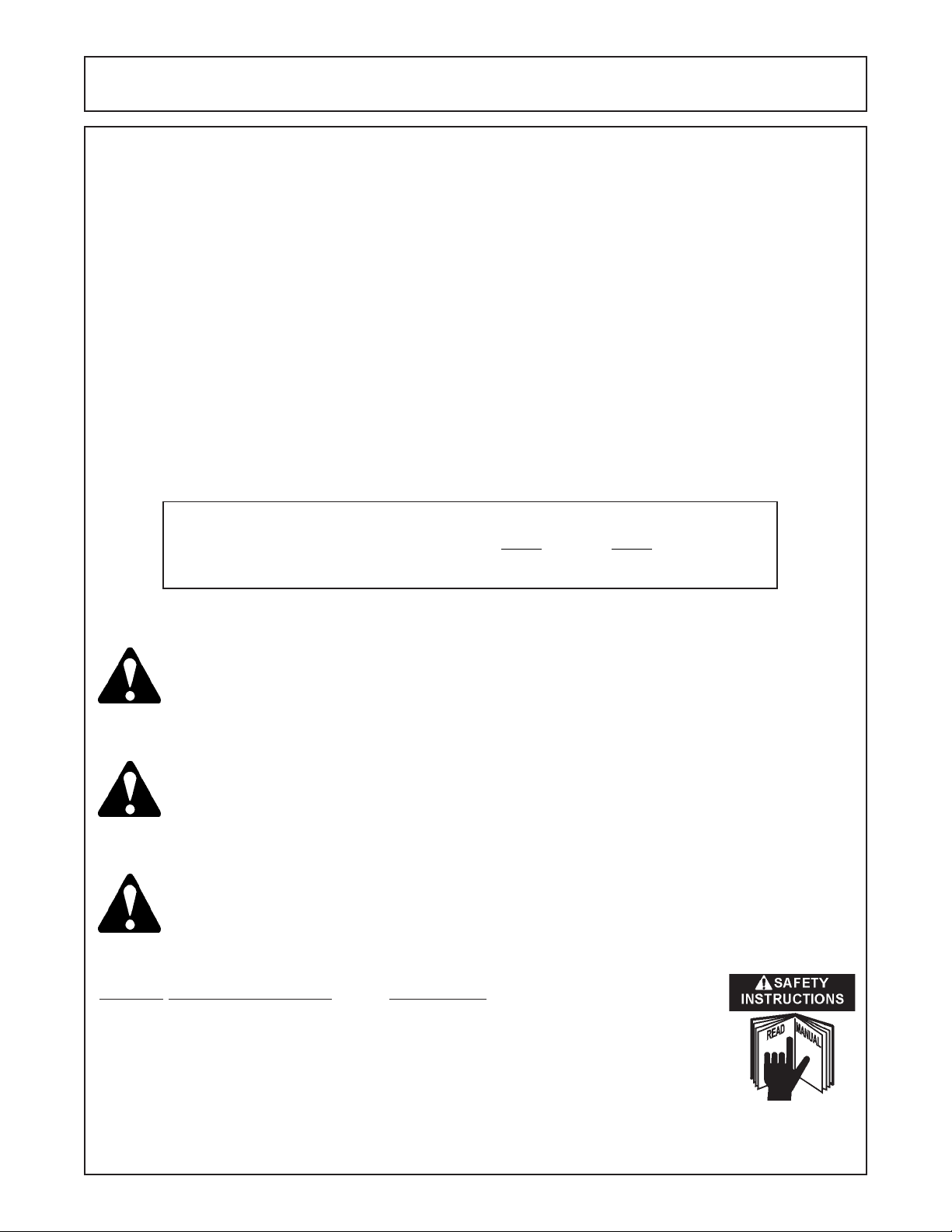
BEFORE YOU START!! Read the safety messages on the implement and shown in your manual.
Observe the rules of safety and common sense!
WARRANTY INFORMATION:
Read and understand the complete Warranty Statement found in this Manual. Fill out the Warranty Registration Form
in full and return it to within 30 Days. Make certain the Serial Number of the Machine is recorded on the Warranty Card
and on the Warranty Form that you retain. The use of “will-fit” parts will void you warranty and can cause catastrophic
failure with possible injury or death
Page 3

BE SAFE!
BE ALERT!
BE ALIVE!
BE TRAINED
before operating
the Mower!
Safety T raining
Makes the Difference
In order to reduce accidents and enhance the safe operation of mowers, Alamo Industrial, in cooperation
with other industry manufacturers has developed the AEM/FEMA Industrial and Agricultural Mower Safety
Practices video and guide book.
The video will familiarize and instruct mower-tractor operators in safe practices when using industrial and
agricultural mowing equipment. It is important that Every Mower Operator be educated in the operation of
their mowing equipment and be able to recognize the potential hazards that can occur while operating a
mower . This video, along with the mower operator’ s manual and the warning messages on the mower, will
significantly assist in this important education.
Y our Authorized Alamo Industrial Dealer may have shown this video and presented you a DVD V ideo
when you purchased your mower . If you or any mower operator have not seen this video, Watch the
Video, Read this Operator’s Manual, and Complete the Video Guidebook before operating your new
mower . If you do not understand any of the instructions included in the video or operator’ s manual or if you
have any questions concerning safety of operation, contact your supervisor, dealer or Alamo Industrial.
If you would like a VHS video tape of the video, please email AEMVideo@alamo-group.com or Fax AEM
VHS V ideo at (830) 372-9529 or mail in a completed copy of the form on the back of this page to AEM
VHS V ideo 1502 E W alnut Street, Seguin, TX 78155. and request the VHS video version. Please include
your name, mailing address, mower model and serial number .
Every operator should be trained for each piece of equipment (Tractor and Mower), understand the intended
use, and the potential hazards before operating the equipment.
Page 4

Alamo Industrial is willing to provide
one (1) AEM Mower Safety Practices Video
Please Send Me: VHS Format – AEM/FEMA Mower Operator Safety Video
DVD Format – AEM/FEMA Mower Operator Safety V ideo
Mower Operator’s Manual
AEM Mower Operator’s Safety Manual
Requester Name:
Requester Address:
City
State
Zip Code
Mower Model: Serial Number:
Date Purchased: Dealer Salesperson:
Dealership Name: Dealership Location:
Phone:
Mail to:
Or Fax to:
Or Email to:
AEM V ideo Services
1502 E Walnut street
Seguin, TX 78155
(830) 372-9529
AEMVideo@alamo-group.com
Page 5

TABLE OF CONTENTS
SAFETY SECTION ...................................................................................................................................... 1-1
Safety Information.............................................................................................................................1-2
Work Area Preparation .....................................................................................................................1-9
Decal Location ................................................................................................................................1-13
Safety Decals.................................................................................................................................. 1-15
Federal Laws & Regulations...........................................................................................................1-18
INTRODUCTION SECTION ...........................................................................................................................2-1
ASSEMBLY SECTION ................................................................................................................................ 3-1
Installation ....................................................................................................................................... 3-2
Precautions .......................................................................................................................................3-2
Hydraulic Schematic.........................................................................................................................3-3
OPERATION SECTION .................................................................................................................................4-1
Pre-Startup (Daily Check List)..........................................................................................................4-2
Blade & Disc Preparation .................................................................................................................4-3
Start Up.............................................................................................................................................4-3
Normal Operation..............................................................................................................................4-4
MAINTENANCE SECTION.... .. . .. .. . .. .. . .. .. . .................................................................................................... 5-1
General Maintenance........................................................................................................................5-2
Disassembly & Assembly ................................................................................................................5-2
Bikon Hub .........................................................................................................................................5-4
Motor Mounting Plate .......................................................................................................................5-6
Bolts & Locknuts ..............................................................................................................................5-6
Blade Arm .........................................................................................................................................5-6
Blade Bolts........................................................................................................................................5-6
Installation & Removal of Locking Assembly ...................................................................................5-7
General Instructions........ ...... ..... ...... ..... ...... ..... ...... ...........................................................................5-8
Hub Installation .................................................................................................................................5-9
Page 6

Page 7

SAFETY
SECTION
Safety Section 1-1
Page 8
SAFETY
A safe and careful operator is the best operator . Safety is of primary importance to the manufacturer and should be to the owner/operator . Most accidents can be avoided by being aware of
your equipment, your surroundings, and observing certain precautions. The first section of this
manual includes a list of Safety Messages that, if followed, will help protect the operator and
bystanders from injury or death. Read and understand these Safety Messages before assembling, operating or servicing this implement. This equipment should only be operated by those
persons who have read the Manual, who are responsible and trained, and who know how to do
so safely and responsibly .
The Safety Alert Symbol combined with a Signal Word, as seen below, is used throughout this
manual and on decals which are attached to the equipment. The Safety Alert Symbol means:
“ATTENTION! BECOME ALERT! YOUR SAFETY IS INVOLVED!” The Symbol and Signal
Word are intended to warn the owner/operator of impending hazards and the degree of possible
injury faced when operating this equipment..
Practice all usual and customary safe working precautions and
above all---remember safety is up to YOU. Only YOU can prevent
serious injury or death from unsafe practices.
CAUTION! The lowest level of Safety Message; warns of possible injury. Decals
located on the Equipment with this Signal Word are Black and Yellow.
WARNING! Serious injury or possible death! Decals are Black and Orange.
DANGER! Imminent death/critical injury. Decals are Red and White. (SG-1)
READ, UNDERSTAND, and FOLLOW the following Safety
Messages. Serious injury or death may occur unless care is
taken to follow the warnings and instructions stated in the Safety
Messages. Always use good common sense to avoid hazards.
(SG-2)
GRIZZLY 52 01/05
© 2005 Alamo Group Inc.
Safety Section 1-2
Page 9
SAFETY
PELIGRO!
DANGER!
WARNING!
WARNING!
Si no lee Ingles, pida ayuda a alguien que
si lo lea para que le traduzca las medidas
INSTRUCTIVO!
¡LEA EL
de seguridad. (SG-3)
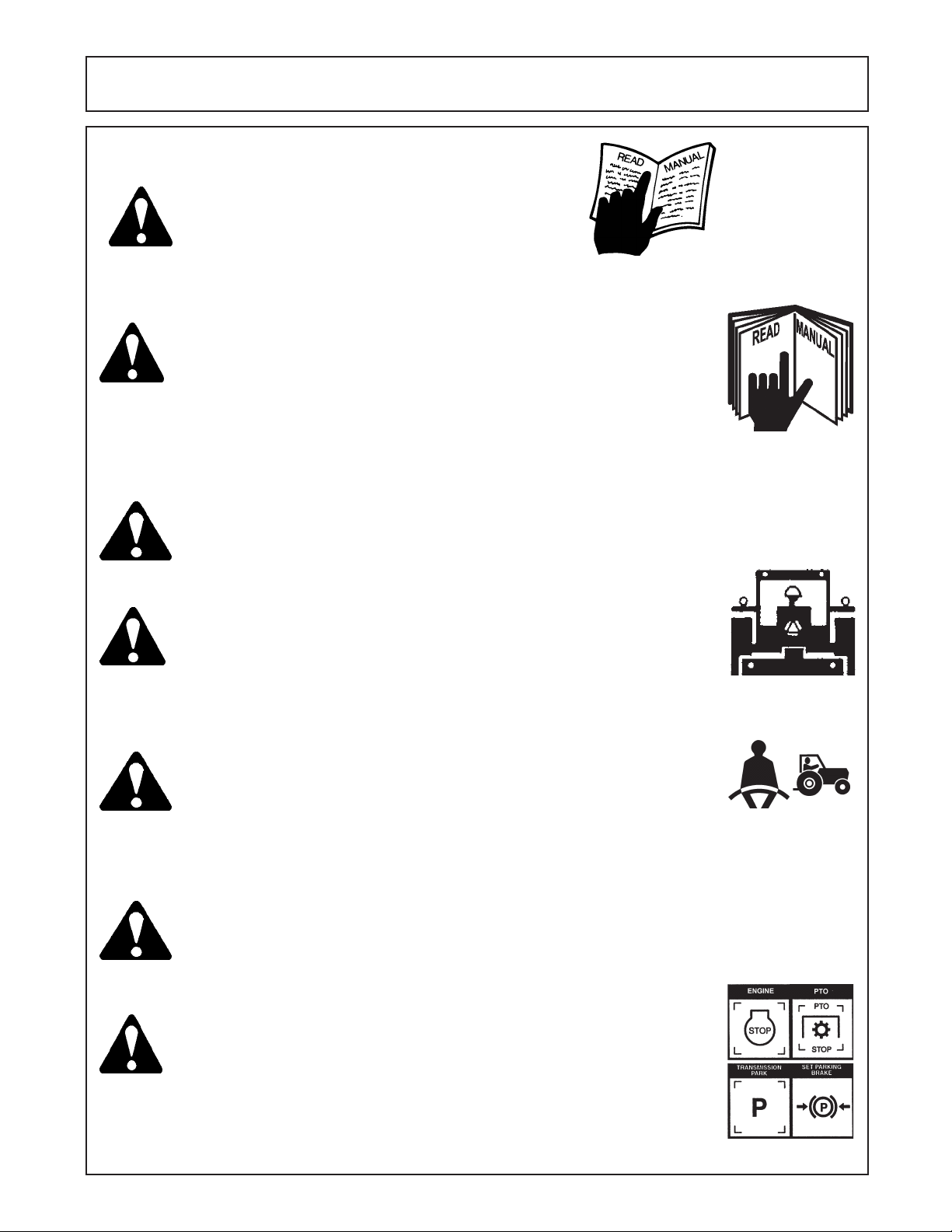
Never operate the Tractor or Implement until you have read and
completely understand this Manual, the Tractor Operator’s Manual,
and each of the Safety Messages found in the Manual or on the Tractor
and Implement. Learn how to stop the tractor engine suddenly in an
emergency. Never allow inexperienced or untrained personnel too
operate the Tractor and Implement without supervision.
Make sure
the operator has fully read and understood the manuals prior to
operation. (SG-4)
Always maintain the safety decals in good readable condition. If the decals are missing, damaged,
or unreadable, obtain and install replacement decals immediately. (SG-5)
Make certain that the “Slow Moving Vehicle” (SMV) sign is installed in
such a way as to be clearly visible and legible. When transporting the
Equipment use the Tractor flashing warning lights and follow all local traffic
regulations. (SG-6)
WARNING!
Operate this Equipment only with a Tractor equipped with an
approved roll-over-protective system (ROPS). Always wear seat
belts. Serious injury or even death could result from falling off the
tractor--particularly during a turnover when the operator could be
pinned under the ROPS. (SG-7)
WARNING!
Do not modify or alter this Implement. Do not permit anyone to modify or alter this Implement,
any of its components or any Implement function. (SG-8)
DANGER!
BEFORE leaving the tractor seat, always engage the brake and/or set
the tractor transmission in parking gear, disengage the PTO, stop the
engine, remove the key, and wait for all moving parts to stop. Place the
tractor shift lever into a low range or parking gear to prevent the tractor
from rolling. Never dismount a Tractor that is moving or while the engine
is running. Operate the Tractor controls from the tractor seat only.
GRIZZLY 52 01/05
© 2005 Alamo Group Inc.
(SG-9)
Safety Section 1-3
Page 10
SAFETY
DANGER!
DANGER!
WARNING!
DANGER!
DANGER!
Never allow children or other persons to ride on the Tractor or Implement.
Falling off can result in serious injury or death.
(SG-10)
Never allow children to operate or ride on the Tractor or Implement.
(SGM-11)
Do not mount the Tractor while the tractor is
moving. Mount the Tractor only when the
Tractor and all moving parts are completely
stopped.
(SG-12)
Start tractor only when properly seated in the Tractor seat. Starting a
tractor in gear can result in injury or death. Read the Tractor operators
manual for proper starting instructions.
(SG-13)
Never work under the Implement, the framework, or
any lifted component unless the Implement is
securely supported or blocked up to prevent sudden
or inadvertent falling which could cause serious
injury or even death. (SG-14)
DANGER!
WARNING!
CAUTION!
Do not operate this Equipment with hydraulic oil
leaking. Oil is expensive and its presence could present a hazard. Do
not check for leaks with your hand! Use a piece of heavy paper or
cardboard. High-pressure oil streams from breaks in the line could
penetrate the skin and cause tissue damage including gangrene. If oil
does penetrate the skin, have the injury treated immediately by a
physician knowledgeable and skilled in this procedure. (SG-15)
The operator and all support personnel should wear hard hats,
safety shoes, safety glasses, and proper hearing protection at all
times for protection from injury including injury from items thrown by
the equipment. (SG-16)
PROLONGED EXPOSURE TO LOUD NOISE MAY CAUSE PERMANENT HEARING LOSS! Tractors with or without an Implement
attached can often be noisy enough to cause permanent hearing
loss. We recommend that you always wear hearing protection if the
noise in the Operator’s position exceeds 80db. Noise over 85db
over an extended period of time will cause severe hearing loss.
Noise over 90db adjacent to the Operator over an extended period of
time will cause permanent or total hearing loss. Note: Hearing loss
from loud noise [from tractors, chain saws, radios, and other such
sources close to the ear] is cumulative over a lifetime without hope
of natural recovery. (SG-I7)
GRIZZLY 52 01/05
© 2005 Alamo Group Inc.
Safety Section 1-4
Page 11
SAFETY
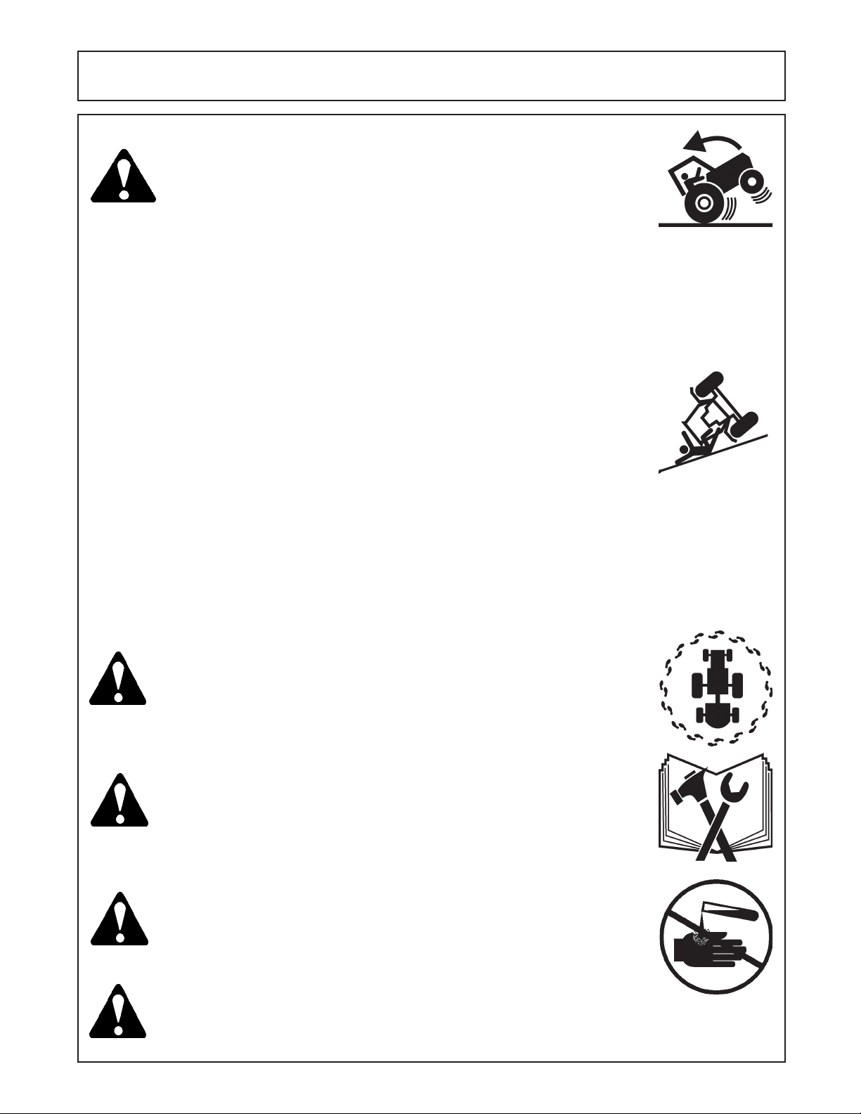
WARNING! Transport only at safe speeds. Serious accidents and injuries can result
from operating this equipment at unsafe speeds. Understand the Tractor
and Implement and how it handles before transporting on streets and
highways. Make sure the Tractor steering and brakes are in good condition and operate properly .
Before transporting the Tractor and Implement, determine the safe
transport speeds for you and the equipment.
the following rules:
Test the tractor at a slow speed and increase the speed slowly.
1.
Apply the Brakes smoothly to determine the stopping
characteristics of the Tractor and Implement.
As you increase the speed of the Tractor the stopping distance
increases. Determine the maximum safe transport speed for
you and this Equipment.
Test the equipment at a slow speed in turns. Increase the speed
2.
through the turn only after you determine that it is safe to operate
at a higher speed. Use extreme care and reduce your speed when
turning sharply to prevent the tractor and implement from turning
over. Determine the maximum safe turning speed for you and this
equipment before operating on roads or uneven ground.
Only transport the Tractor and Implement at the speeds that you
3.
have determined are safe and which allow you to properly control the
equipment.
Be aware of the operating conditions. Do not operate the Tractor with weak or faulty brakes. When operating down
a hill or on wet or rain slick roads, the braking distance increases: use extreme care and reduce your speed.
When operating in traffic always use the Tractor’s flashing warning lights and reduce your speed. Be aware of
traffic around you andwatch out for the other guy . (SG-19)
Make sure you abide by
WARNING!
WARNING!
WARNING!
DANGER!
Never attempt to lubricate, adjust, or remove material from the
Implement while it is in motion or while tractor engine is running. Make
sure the tractor engine is off before working on the Implement.
(SG-20)
Periodically inspect all moving parts for wear and replace when
necessary with authorized service parts. Look for loose fasteners,
worn or broken parts, and leaky or loose fittings. Make sure all pins
have cotter pins and washers. Serious injury may occur from not
maintaining this machine in good working order. (SG-21)
Always read carefully and comply fully with the manufacturers instructions when handling oil, solvents, cleansers, and any other chemical
agent. (SG-22)
Never run the tractor engine in a closed building or without adequate
ventilation. The exhaust fumes can be hazardous to your health.
(SG-23)
GRIZZLY 52 01/05
© 2005 Alamo Group Inc.
Safety Section 1-5
Page 12
SAFETY
DANGER!
KEEP AWAY FROM ROTATING ELEMENTS to prevent entanglement
and possible serious injury or death. (SG-24)
DANGER!
Never allow children to play on or around Tractor or Implement. Children can slip or fall off the
Equipment and be injured or killed. Children can cause the Implement to shift or fall crushing
DANGER!
themselves or others.
NEVER use drugs or alcohol immediately before or while operating the
(SG-25)
Tractor and Implement. Drugs and alcohol will affect an operator’s
alertness and coordination and therefore affect the operator’s ability to
operate the equipment safely. Before operating the Tractor or Implement, an operator on prescription or over-the-counter medication must
consult a medical professional regarding any side effects of the medication that would hinder their ability to operate the Equipment safely.
NEVER knowingly allow anyone to operate this equipment when their
alertness or coordination is impaired. Serious injury or death to the
operator or others could result if the operator is under the influence of
drugs or alcohol. (SG-27)
DANGER! Operate the Tractor and/or Implement controls only while properly seated in the Tractor seat with
the seat belt securely fastened around you. Inadvertent movement of the Tractor or Implement may
cause serious injury or death. (SG-29)
WARNING!
DANGER!
DANGER!
WARNING!
Mow only in conditions where you have clear visibility in daylight or with adequate artificial lighting.
Never mow in darkness or foggy conditions where you cannot clearly see at least 100 yards in front
and to the sides of the tractor and mower. Make sure that you can clearly see and identify
passersby, steep slopes, ditches, drop-offs, overhead obstructions, power lines, debris and foreign
objects. If you are unable to clearly see this type of items discontinue mowing. (SGM-1)
There are obvious and hidden potential hazards in the operation of this
Mower. REMEMBER! This machine is often operated in heavy brush
and in heavy weeds. The Blades of this Mower can throw objects if
shields are not properly installed and maintained. Serious injury or
even death may occur unless care is taken to insure the safety of the
operator, bystanders, or passersby in the area. Do not operate this
machine with anyone in the immediate area. Stop mowing if anyone
is within 100 yards of mower. (SGM-2)
The rotating parts of this machine have been designed and tested for rugged use. However,
they could fail upon impact with heavy, solid objects such as steel guard rails and concrete
abutments. Such impact could cause the broken objects to be thrown outward at very high
velocities. To reduce the possibility of property damage, serious injury, or even death, never
allow the cutting blades to contact such obstacles. (SGM-4)
Do not mow with two machines in the same area except with Cab tractors with the windows closed.
(SGM-11)
GRIZZLY 52 01/05
© 2005 Alamo Group Inc.
Safety Section 1-6
Page 13
SAFETY
WARNING! Extreme care should be taken when operating near loose objects such
as gravel, rocks, wire, and other debris. Inspect the area before
mowing. Foreign objects should be removed from the site to prevent
machine damage and/or bodily injury or even death. Any objects that
cannot be removed must be clearly marked and carefully avoided by
the operator. Stop mowing immediately if blades strike a foreign
object. Repair all damage and make certain rotor or blade carrier is
balanced before resuming mowing. (SGM-5)
WARNING!
Many varied objects, such as wire, cable, rope, or chains, can become entangled in the operating
parts of the mower head. These items could then swing outside the housing at greater velocities
than the blades. Such a situation is extremely hazardous and could result in serious injury or even
death. Inspect the cutting area for such objects before mowing. Remove any like object from the
WARNING!
site. Never allow the cutting blades to contact such items.
Avoid mowing in reverse direction when possible. Check to make sure there are no persons are
(SGM-6)
behind the mower and use extreme care when mowing in reverse. Mow only at a slow ground speed
where you can safely operate and control the tractor and mower. Never mow an area in the reverse
direction that you have not inspected and removed debris or foreign material. (SGM-8)
WARNING! Do not put hands or feet under mower decks. Blade Contact can result
serious injury or even death. (SGM-9)
DANGER!
Replace bent or broken blade with new blades. NEVER ATTEMPT TO STRAIGHTEN BLADES
SINCE THIS WILL LIKELY CRACK OR OTHERWISE DAMAGE THE BLADE WITH
SUBSEQUENT FAILURE AND POSSIBLE SERIOUS INJURY FROM THROWN BLADES.
(SGM-10)
DANGER!
Rotary Mowers are capable under adverse conditions of throwing objects for great distances
(100 yards or more) and causing serious injury or death. Follow safety messages carefully.
STOP MOWING IF PASSERSBY ARE WITHIN 100 YARDS UNLESS:
-Front and Rear Deflectors are installed and in good, working condition;
-Mower Head is running close to and parallel to the ground without exposed Blades;
-Passersby are outside the existing thrown-object zone;
-All areas have been thoroughly inspected and all foreign material such as rocks, cans, glass,
and general debris has been removed.
NOTE:
Where there are grass and weeds high enough to hide debris that could be struck by the
blades, the area should be: inspected and large debris removed, mowed at an intermediate height, inspected closely with any remaining dsebris being removed, and mowed
again at desired final height. (SBM-1)
DANGER!
Use extreme caution when raising the Mower head. Stop the Blades from turning when the
Mower Head is raised and passersby are within 100 yards. Raising the Mower head exposes
the Cutting Blades which creates a potentially serious hazard and can cause serious injury
by objects thrown from the Blades or by contact with the Blades. (SBM-2)
GRIZZLY 52 01/05
© 2005 Alamo Group Inc.
Safety Section 1-7
Page 14
SAFETY
WARNING!
WARNING!
WARNING!
DANGER!
DANGER!
Never Leave the mower unattended while the head is in the
raised position. The mower could fall causing serious injury
to anyone who might inadvertently be under the mower
(SBM-4)
.
The rotating parts of this machine continue to rotate even after the Tractor has been turned off. The
operator should remain in his seat for 60 seconds after the brake has been set, the PTO
disengaged, the tractor turned off, and all evidence of rotation has ceased. (SBM-5)
“Wait a minute...Save a life!”
Relieve hydraulic pressure prior to doing any maintenance or repair work on the Implement.
Place the Mower Head on the ground or securely supported on blocks or stands, disengage
the PTO, and turn off the engine. Push and pull the control Levers or Joystick several times
to relieve pressure prior to starting any maintenance or repair work. (SBM-6)
Always keep a careful lookout and use extreme care when working
around overhead obstructions. Never allow the Mower head or boom
within 10 feet of any power line. When working close to overhead power
lines consult your electric company for a safe code of operation.
(SBM-7)
Never operate the Tractor and Mower Unit without an OPS (Operators
Protective Structure) or Cab to prevent injury from objects thrown from
ground or from overhead trimming. Stop mowing if workers or passersby
are with in 100 yards. (SBM-9)
DANGER!
The Mower shaft speed must not - UNDER ANY CIRCUMSTANCES - exceed 1800 RPM. (SBM-15)
In addition to the design and configuration of this Implement, including Safety Signs and Safety Equipment, hazard
control and accident prevention are dependent upon the awareness, concern, prudence, and proper training of
personnel involved in the operation, transport, maintenance, and storage of the machine. Refer also to Safety
Messages and operation instruction in each of the appropriate sections of the Tractor and Equipment Manuals.
Pay close attention to the Safety Signs affixed to the Tractor and Equipment. (SG-18)
PARTS INFORMATION
Alamo Industrial mowers use balanced and matched system components for blade carriers, blades,
cuttershafts, knives, knife hangers, rollers, drivetrain components, and bearings. These parts are made and
tested to Alamo Industrial specifications. Non-genuine "will fit" parts do not consistently meet these
specifications. The use of “will fit” parts may reduce mower performance, void mower warranties, and present
a safety hazard. Use genuine Alamo Industrial mower parts for economy and safety. (SPAM-1)
SEE YOUR ALAMO DEALER
GRIZZLY 52 01/05
© 2005 Alamo Group Inc.
Safety Section 1-8
Page 15

SAFETY
WORK AREA PREPARATION
It is the intention of this manual to inform owners and their operators of some of the dangers inherent in the
use of this epuipment. The machine is an effective, durable and simple tool and when used correctly will
provide satisfactory results with minimal danger. These warnings are intended to help ensure that
operators and maintenance personnel treat the machine with the respect and care that a powered, edged
tool demands and enjoy trouble-free and safe usage. Do not let accidents happen through ignorance,
carelessness or improper use.
1. Keep children, bystanders and animals a minimum of 300 feet, (100 meters) away from the work area.
2. Post "DANGER" signs as in Figure 1.2 to warn pedistrians and vehicles of the danger and to prevent
them from inadvertently wandering into the area. Obey local regulations and by-laws wherever applicable.
GRIZZLY 52 01/05
© 2005 Alamo Group Inc.
Safety Section 1-9
Page 16

SAFETY
3. An area to be cut must first be inspected for objects that could be thrown or that could damage the
machine. Walk through the area looking for overgrown fences, boulders and rocks, culverts, stumps or
metal objects. Mark the inspected area with flags. If the area is dense and cannot be walked thoroughly it
may be necessary to inspect a smaller area as well as possible, then trim away the part that has been
inspected and can safely be removed. Walk each new area again and repeat the inspection before cutting
more away. Repeat as often as necessary until the area is cleared. It can be damaging and/or dangerous
to work the brushcutter in an area that has not been visually inspected. Note that the DANGER signs should
be placed at least 300 feet beyond the perimeter of the area to be worked, not just 300 feet from where the
machine started operating!
4. Once an area has been cleared, move the DANGER signs and cutting area flags and repeat step 3
above.
It is convenient in many cases to work in 300 foot sections. Move the first Danger sign to the beginning of
the freshly cleared area, place it, then take the first cutting area flag up to the end of the freshly cleared area
300 feet away. Walk and inspect the next 300 feet and place the second cutting area flag. Pick up the
second DANGER sign, and take it a further 300 feet along the road or trail. Note that in many cases the
DANGER area will extend in front of and behind the machine as well as along each side. Post signs
accordingly.
5. The operator's cab must be protected by a strong wire screen or materials capable of withstanding an
object thrown by the Grizzly.
6. Should a vehicle or pedestrian enter the defined DANGER area, immediately stop cutting until the area
is clear again.
7. Objects tend to be thrown out from under the shroud in the direction of rotation and towards the raised
edge of the shroud. Avoid cutting with the head titled at such an angle that objects would be thrown towards
the operator's cab. See figure 1.5 Titling The Cutter Head.
GRIZZLY 52 01/05
© 2005 Alamo Group Inc.
Safety Section 1-10
Page 17

SAFETY
Reversing the direction of rotation of the cutting head on side opening machines increases the chances of
objects being thrown out because of the position of the "gate" in relation to the boom arm.
When clearing brush and small trees, start at the top and then lower the head down through the brush while
sweeping from right to left. This avoids clogging the head with mulched material.
NOTE: Keep the cutting head titled away from the operator when it is raised to avoid throwing splinters
towards the cab.
WARNING! Engage the cutting head with the tractor engine at idle. If the cutter is engaged at high rpm,
severe damage to the coupling could occur.
Always disengage the Grizzly before leaving the machine. Place the Control Valve in the OFF position and
disengage the power take-off. Shut off the engine. A preventor or locking device must be installed on the
control valve handle to prevent inadvertent or accidental engagement when the operator is out of the cab.
GRIZZLY 52 01/05
© 2005 Alamo Group Inc.
Safety Section 1-11
Page 18

SAFETY
A TTENTION!
This unit was shipped with an Operator’s Manual Specifically designed to remain with the unit at all times. This
manual is to be stored in the protective canister shipped with this unit. Because it is not feasible to attach the
protective canister to the unit directly due to severe conditions in which it operates, the canister must be
installed in a secure area such as the operator’s station. Choose a location that allows convenient access by
the operator and easily allows removal of the Operators Manual. Use the adhesive and/or the included fasteners
to securely attach the canister. Operator must read the Operator’s Manual prior to using the unit.
GRIZZLY 52 01/05
© 2005 Alamo Group Inc.
Safety Section 1-12
Page 19

1
Clean Surface
With Alcohol
Before Applying
Tape.
SAFETY
2
3
Cover Holes
With Tape to
Prevent
Moisture From
Entering
Canister.
6
7
4
5
ITEM P ART NO. QT Y DESCRIPTION
1 02977385 1 Sq. Canister
2 02968143 2 1/2' Tape 3M Back to Back
3 02977417 1 Decal, Op. Man. Inside
4 10058000 4 Bolt
5 00024100 4 Flatwasher
6 02967444C 4 Oper. Man. (Inside)
7 00017000 4 Lockwasher
8 02959924 4 Nut Toplock
8
GRIZZLY 52 01/05
© 2005 Alamo Group Inc.
Safety Section 1-13
Page 20

DECAL LOCATION
SAFETY
ITEM PART NO. QTY LEVEL DESCRIPTION
1 00769736 1 WARNING Use/Repair Shield & Guards
2 00769737 2 DANGER Cutting Blades/Thrown Objects
3 02925100 1 IMPORTANT Genuine Parts
4 02967827 1 DANGER Multi-Hazard
5 02967867 2 DANGER Safety Gate Operation
6 02972284 2 LOGO Grizzly
7 02965262 1 WARNING Hose Burst
8 02973050 3 DANGER Danger Stand Clear
9 02973051 1 INSTRUCT Read Operators Instructions
10 02973052 1 DANGER Keep Clear Over Head Wires
11 00725746 1 PELIGRO Peligro Spanish Translation
GRIZZLY 52 01/05
© 2005 Alamo Group Inc.
Safety Section 1-14
Page 21

SAFETY
1 - 00769736
7 - 02965262
2 - 00769737
5 - 02967867
Decals Not Shown
10 - 02973052 - Danger Keep Clear Wires
9 - 02973051 - Read Operator Instructions
8 - 02973050 - Danger Stand Clear
GRIZZLY 52 01/05
© 2005 Alamo Group Inc.
6 - 02972284
Safety Section 1-15
Page 22

SAFETY
GRIZZLY 52 01/05
© 2005 Alamo Group Inc.
4 - 02967827
3 - 02925100
Safety Section 1-16
Page 23

SAFETY
11 - 00725746
GRIZZLY 52 01/05
© 2005 Alamo Group Inc.
Safety Section 1-17
Page 24

SAFETY
FEDERAL LAWS AND REGULATIONS
This section is intended to explain in broad terms the concept and effect of federal laws and regulations concerning
employer and employee equipment operators. This section is not intended as a legal interpretation of the law and
should not be considered as such.
Employer-Employee Operator Regulations
U.S. Public Law 91-596 (The Williams-Steiger Occupational and Health Act of 1970) OSHA
This Act Seeks:
“...to assure so far as possible every working man and woman in the nation safe and healthful working conditions
and to preserve our human resources...”
DUTIES
Sec. 5 (a) Each employer(1) shall furnish to each of his employees employment and a place of employment which are free from recognized
hazards that are causing or are likely to cause death or serious physical harm to his employees;
(2) shall comply with occupational safety and health standards promulgated under this Act.
(b) Each employee shall comply with occupational safety and health standards and all rules, regulations and
orders issued pursuant to this Act which are applicable to his own actions and conduct.
OSHA Regulations
OSHA regulations state in part: “At the time of initial assignment and at least annually thereafter, the employer
shall instruct every employee in the safe operation and servicing of all equipment with which the employee is, or will
be involved.”
Employer Responsibilities:
T o ensure employee safety during T ractor and Implement operation, it is the employer’s responsibility to:
1. Train the employee in the proper and safe operation of the Tractor and Implement.
2. Require that the employee read and fully understand the Tractor and Implement Operator’s manual.
3. Permit only qualified and properly trained employees to operate the Tractor and Implement.
4. Maintain the Tractor and Implement in a safe operational condition and maintain all shields and guards on the
equipment.
5. Ensure the Tractor is equipped with a functional ROPS and seat belt and require that the employee operator
securely fasten the safety belt and operate with the ROPS in the raised position at all times.
6. Forbid the employee operator to carry additional riders on the Tractor or Implement.
7. Provide the required tools to maintain the Tractor and Implement in a good safe working condition and provide
the necessary support devices to secure the equipment safely while performing repairs and service.
8. Require that the employee operator stop mowing if bystanders or passerbys come within 100 yards.
Child Labor Under 16 Y ears of Age
Some regulations specify that no one under the age of 16 may operate power machinery . It is your responsibility
to know what these regulations are in your own area or situation. (Refer to U.S. Dept. of Labor, Employment
Standard Administration, Wage & Home Division, Child Labor Bulletin #102.)
GRIZZLY 52 01/05
© 2005 Alamo Group Inc.
Safety Section 1-18
Page 25

INTRODUCTION
SECTION
Introduction Section 2-1
Page 26

INTRODUCTION
The Grizzly is a dependable machine designed specifically for removal of brush, scrub, shrubbery, small trees and
other undergrowth in rural areas. This machine is not recommended for use in populated and built-up areas.
The Grizzly utilizes hydraulically driven rotating steel blades, rotating disc with cutter bits, or a rotating arbor with
flail hammers. It is usually mounted on the hydraulic boom arm of a tractor, excavator or similar carrier, and
employs the hydraulics system of the carrier for operation of the hydraulic drive motor.
A steel shroud encloses the cutting disc to contain the cuttings and direct them downwards. However, it is
possible for occasional ricochets to escape from under the shroud, particularly if the Grizzly is tipped away from
the horizontal. (See "Safe Section", Section 1). Special precautions must be taken when using the Grizzly in busy
traffic areas.
Under no circumstances will Alamo Industrial accept responsibilty or liability for personal injury or property
damage resulting from the operation of this machine. DO NOT use this machine in the vicinity of people, animals
or structures. Such use is entirely at the risk and responsibility of the operator(s).
The cutter bits are mounted on the rim, upper face and lower face. The disc is mounted on a steel shaft driven
directly by the hydraulic motor.
It is the intention of this manual to inform owners and their operators of some of the dangers inherent in the use
of this equipment. The machine is an effective, durable and simple tool and when used correctly will provide
satisfactory results with minimal danger. These warnings are intended to help ensure that operators and
maintenance personnel treat the machine with the respect and care that a powered, edged tool demands and
enjoy trouble-free and safe usage. Do not let accidents happen through ignorance, carelessness or improper use.
Shock loads are absorbed by the cross over relief valve on the driven motor.
The brushcutters have been designed to help alleviate the environmental problems associated with the increased
use of chemical defoliants.
Suited for clearing roadway or off-highway rights-of-way, clearing of power line underbrush, pipeline rights-of-way,
and forestry thining in dense growth, the brushcutters are both efficient and environmentally acceptable.
Brushcutters are so efficient that the operator can pass from dense brush cutting to grass cutting with the same
machine.
GRIZZLY 52 01/05
© 2005 Alamo Group Inc.
CUTTING BITS, BLADE, & HAMMER
Introduction Section 2-2
Page 27

INTRODUCTION
GENERAL INSTRUCTIONS
The Grizzly has been designed to help alleviate the environmental problems associated with the increased
use of chemical defoliants.
Suited for clearing roadway or off-highway right-of-way, clearing of power line underbrush, pipeline right-of-way and
forestry thinning in dense growth, the Grizzly is both efficient and environmentally acceptable.
The Grizzly is so efficient that the operator can pass from dense brush cutting to grass cutting with the same
machine.
The Grizzly can be adapted to various makes and models of equipment. It is simple and efficient to operate.
It's cutting features range from grass to small trees. The maximum material thickness should not exceed 6"
in diameter.
This is the Safety-Alert symbol. When you see this symbol on your machine or in these
instructions, be alert to the potential for personal injury.
Follow recommended precautions and safe operating practices.
DANGER! A signal word - DANGER, WARNING, or CAUTION - is used with the Safety Alert symbol.
DANGER identifies the most serious hazards.
WARNING! Safety signs with signal word WARNING are typically used to point out more serious
hazards.
CAUTION! General precautions are listed on CAUTION safety sign. CAUTION also calls
attention to safety messages in these instructions.
SAFETY FIRST!
MAKE EVERY DAY A HOLIDAY FROM ACCIDENTS!!
GRIZZLY 52 01/05
© 2005 Alamo Group Inc.
Introduction Section 2-3
Page 28

Page 29

ASSEMBLY
SECTION
Assembly Section 3-1
Page 30

ASSEMBLY
PRE-INSTALLATION
Prior to installing the Girzzly on the carrier, check to make sure that the combination of carrier and Grizzly is correct
and is as ordered.
INSTALLATION
The cutter requires a constant flow of hydraulic oil and must be provided with a supply that will not be reduced
when another function of the machine is used simultaneously.
The control valve must be of the motor spool type that will allow the Grizzly to gradually slow to a stop rather than
"lock up" when the control is moved to the "OFF" position. If a motor spool equipped control valve cannot be
provided then a system of circulating check valves must be used in the vicinity of the drive motor.
The control valve may be electically operated, (HED or STANLEY type), or pressure compensated manual, (Char
Lynn etc.). Some operators prefer a dual direction Parker valve, (PARKER #VS 32ACA9).
The drive motor must be provided with a cross over relief valve to protect it from pressure spikes if the blades
strike a rock, stump or other immovable object.
If dual rotation is preferred, a dual action cross over relief valve is required.
A drain line must be installed from the motor case to the tank. The case drain is provided to prevent oil from
building up behind the output shaft seal. This is particularly important when dual rotation is used. If possible
connect the drain line to the upper part of the tank.
The case drain line must be minimum 1/2" single braid to prevent the line from being crimped, thus shuting off the
oil flow. There is, normally, very little pressure in this line, however it must remain open to allow any oil behind the
seal to escape.
Hydraulic line sizes are important. Pressure lines should be minimum 1" double braid hydraulic lines. The return
line must also be 1" but need only be single braid. Note that if dual rotation is used both lines become pressure
lines so they both must be double braid.
PRECAUTIONS
The maximum oil pressure permitted with the low pressure gear type motor is 2000 p.s.i. The control valve should
be equipped with a pressure relief valve set below 2000 p.s.i.
NOTE:
On medium pressure machines a modified gear type motor may be used allowing pressures up to 2500 p.s.i. High
pressure machines use a high pressure piston type motor. This motor is capable of operating at 3500 p.s.i. with
a correspondingly lower flow rate.
CAUTION! The Grizzly control valve must not be engaged at high engine RPM. When dual direction control is
used, the direction of rotation must not be changed until the cutter head has slowed to a stop.
NOTE: RPM LIMITATION
The shaft speed of the Grizzly must not, under any circumstances, exceed 1800 RPM . Operation in excess
of this maximum RPM may result in damage to component parts and is a safety hazard.
GRIZZLY 52 01/05
© 2005 Alamo Group Inc.
Assembly Section 3-2
Page 31

ASSEMBLY
Note: This is a typical schematic only, refer to the drawing supplied with the machine you purchased for the
appropriate detailed schematic.
HYDRAULIC SCHEMATIC
GRIZZLY 52 01/05
© 2005 Alamo Group Inc.
Assembly Section 3-3
Page 32

ASSEMBLY
ALTERNATE HYDRAULIC SCHEMATIC
GRIZZLY 52 01/05
© 2005 Alamo Group Inc.
Assembly Section 3-4
Page 33

ASSEMBLY
ALTERNATE HYDRAULIC SCHEMATIC
GRIZZLY 52 01/05
© 2005 Alamo Group Inc.
Assembly Section 3-5
Page 34

Page 35

OPERATION
SECTION
Operation Section 4-1
Page 36

OPERATION
IMPORTANT: Read this section carefully and follow the instructions outlined before starting up the machine.
Failure to follow the procedures outlined in this manual may result in personal injury to the operator or bystanders,
or in damage to the machine.
Pre-Startup
Operation of the Grizzly must be restricted to operators who have read and completely understand all Safety
Rules, Precautions and Operating Functions of both Tractor (carrier) and the Alamo Grizzly.
Do not operate the carrier or the Grizzly when tired, ill or under the influence of drugs, alcohol or medication.
The greatest danger when operating the machine is the possibilty of the cutting head throwing debris, wood,
rocks, etc., from under the shroud. To minimize this danger:
Walk around the Grizzly and check it thoroughly for damage, loose bolts, missing cotter pins and wire or
rope etc., possibly wrapped around the shaft.
Peform the operations outlined on the following Daily Check List.
DAILY CHECK LIST
Check:
Grizzly to carrier mounting pins for security & wear Check all cutter blades/bits for condition & retention
Grizzly frame and shroud for damage Main shaft and cutters for wire, rope or other
material wrapped around
Motor and motor baseplate bolts for security Hydraulic lines & connections for chafing, leaks or
looseness
Check all mounting adapter bolts Hydraulic oil level in tank, top up as necessary
Lubricate:
Upper and lower bearing. Use Shell EP2 or equal.
Do not over-grease, one pump of a hand gun is
usually sufficient. Over-greasing will cause high
bearing housing temperature.
Remove:
Material bulid-up inside shroud
Grizzly to carrier hinge pin, again with ordinary,
good quality grease
WARNING! The comsumable wear parts are constructed of specially treated steel of specific composition
to withstand the stresses of operation on the Grizzly. Replace ONLY with genuine Alamo
replacement parts. DO NOT repair if damaged, other than routine sharpening as described in
the Maintenance Section.
GRIZZLY 52 01/05
© 2005 Alamo Group Inc.
Operation Section 4-2
Page 37

OPERATION
Two Blade Arm, Three Blade Disc & Disc (w/ Cutter Bits)
1) Check the attachment of the Grizzly to the carrier to ensure that all attachment point bolts and pins are in good order.
2) Check all hydraulic lines and connections for leaks and security.
3) Check the fluid level in the hydraulic tank.
4) Make sure the control vavle is in the "OFF" position.
Blade Arm/Disc - 1) Check the nuts holding the Blade Arm onto the shaft and the Blades onto the Blade Arm
for tightness and make sure that the nuts are cotter pinned.
2) Being careful of the sharp edges of the Blades, check that the Blades rotate freely on the
Blade Arm/Disc. Figures 1 & 2.
Two Blade Arm w/ Blades
FIGURE 1
Three Blade Rotary Disc
FIGURE 2
Disc - 1) Check cutter bit retention,
e.g. spiral roll pins and lock
rings.
2) Check cutter bit condition.
Figure 3.
FIGURE 3
Start Up
Disc w/ Cutter Bits
Clear all personnel, except the operator, from the vicinity of the machine.
With the Control Valve in the "OFF" position, start up the machine. Bring it up to operating temperature and
check the hydraulic pressure to ensure it is within the operating range. Once it is warmed up reduce the
engine speed to "IDLE".
With the Grizzly horizontal to and about a foot or more above clear ground, momentarily move the Control Valve
to the "CUT" position, then return it to "OFF". As long as no unusual noises are heard from the Grizzly, tilt the
Grizzly towards the cab so that the operator can
see the blades rotating as they slow down. The
cutter should rotate freely. If it does, the Grizzly
is ready for use. If it doesn't, follow the maintenance procedures in the Maintenance Section to
de t e r mine the cause.
Note the direction of rotation. Normal rotation is
clockwise (looking down on the top of the Grizzly).
Note the arrow on the top of the shroud which
indicates normal direction of rotation. See Figure 4.
GRIZZLY 52 01/05
© 2005 Alamo Group Inc.
Operation Section 4-3
FIGURE 4
Page 38

OPERATION
NOTE: Preform the following run-up check over grass if possible to avoid raising dust.
Once the direction of rotation has been determined to be correct and the Control Valve notation indicates
the correct direction (in the case of dual direction installations), return the Grizzly to the horizontal position
a foot or so above the ground and run it up to speed. It will probably be necessary to increase the engine
speed to provide adequate hydraulic pressure/volume to reach maximum shaft speed.
WARNING! DO NOT EXCEED 1800 RPM. The shaft speed of the Grizzly must not - UNDER ANY
CIRCUMSTANCES- exceed 1800 RPM. Operation in excess of the maximum RPM may
result in damage to component parts and is a safety hazard.
Once it is verified that everything is working satisfactorily, shut the machine down and review the Daily
Check List before proceeding.
Normal Operation
CAUTION! First, inspect the area to be cut. Walk through the area looking for rocks, boulders, culverts,
stumps, etc. Mark the area with flags. (See Safety Section for instruction on Work Area
Preparation).
Drive the tractor to the start of the inspected area, lower the cutter head close to the material to be cleared
and engage the cutter. ALWAYS engage the cutter with the tractor engine at IDLE to avoid damage to the
coupling.
Increase the engine speed to bring the cutter speed up to operational level. DO NOT EXCEED1800 RPM
shaft speed. Lower the cutter to the material.
The "GATE" on the cutter shroud is normally on the "front" side of the shroud so the cutting swath is
customarily outwards from the tractor.
Starting close to the tractor, cut or clear the material by sweeping the cutter outwards, then returning over
the cleared area to start the next swath. Keep the cutting head parallel to the ground as far as possible to
keep the debris from spraying outwards. Stop immediately and shut off the engine if the cutter hits a solid
object, or vibrates excessively, and inspect for damage.
!!!!!!CEASE OPERATION IMMEDIATELY IF ANY PERSON OR ANIMAL ENTERS THE WORKING AREA!!!!!
DANGER! DO NOT OPERATE THE GRIZZLY WITHIN 10 FEET OF OVERHEAD POWER LINES!
WARNING! The operator's cab must be protected with a strong wire screen. Avoid cutting with the head
tilted at such an angle that objects could be thrown towards the cab.
WARNING! Only engage the cutting head with the engine at IDLE. Provide a locking device to prevent
accidental engagement when the operator is out of the cab.
GRIZZLY 52 01/05
© 2005 Alamo Group Inc.
Operation Section 4-4
Page 39

MAINTENANCE
SECTION
Maintenance Section 5-1
Page 40

MAINTENANCE
General Maintenance
The importance of regular maintenance and inspection as a means of prolonging the life and maintaining the
efficiency of the Grizzly cannot be overemphasized.
For lubrication use Shell EP2 grease or equal. The bearings are packing during assembly. Each bearings should
be given one 'shot' of grease with a hand gun each day (8 hour shift) before starting up. DO NOT OVER GREASE.
A hot bearing housing usually indicates overgreasing.
Cutter bits may become damaged due to rock impact. It is not necessary to throw away a cutter bit if the carbide
insert is lost. These cutters may be built up with hard surface rod. The cutter must be preheated to 300 degrees
F. Build up with hard surface rod (e.g. Artec Ecoface 60) and post heat then cool slowly. The disc is balanced at
the time of manufacturing. Cutter bits must be of equal weight. If cutter bits are hard surfaced, they must be
weighed. All outer rim bits must be of equal weight to insure balanced operation.
Blades may be sharpened as necessary. It is imperative, however, that the weight of each blade in a pair be the
same. Maximum variation in weight must not exceed 2 oz. After sharpening, file any burrs from the blades and
flail arm. Clean the blade bolt and check the fit to the bushing in the flail arm. Replace the bushing when 50% of
the thickness is worn away. Replace the bolt when the shoulder diameter is 2" in any direction or the pin diameter
reaches 1-1/8" minimum. Replace the blade when the hole reaches 2-1/2" diameter in any direction. Lightly oil
the bolt and bushing before re-assembling. Use new cotter pins in the slotted nuts.
WARNING! The cutter bits, blades, and flail arms, are constructed of specially treated steel of specific
composition to withstand the stresses of operation on the Grizzly. Replace only with genuine Alamo
parts. Do not repair except as noted in paragraph 3.
CAUTION! Many other parts on the Grizzly are of special construction, treatment or composition. These items,
which are clearly indicated on the Parts List, must always be replaced by genuine Alamo parts.
Other items may be replaced from local suppliers provided they are of equal quality and
specification.
At some point in time the bearing will wear out sufficiently to require replacing. Since thise will only occur after
many hours of use it will be appropriate to carefully inspect the shaft, arm, and/or disc for stress damage at that
time while the Grizzly is disassembled. If at all possible have these parts magna-fluxed. If doubtful concerning
either the condition or procedure, contact Alamo or their authorized representative.
Disassembly
- Disconnect and plug the hydraulic lines. Plug the hydraulic connection on the motor.
- Undo the bolts and nuts and remove the disc.
- Undo bolts on motor and remove the motor.
- Undo bolts on motor plate and remove plate.
- Undo bolts on BIKON lock assembly and use bolts to remove lock.
- Undo housing bolts and remove housing.
- Undo locknut and lockwasher and remove.
- Remove shaft from housing.
- Remove bearing from housing.
GRIZZLY 52 01/05
© 2005 Alamo Group Inc.
Maintenance Section 5-2
Page 41

MAINTENANCE
- Using a large pair of snap ring pliers, remove retaining ring from the bottom of the housing.
- Remove bottom cover from housing.
- Wash all parts in solvent and inspect carefully for damage or excessive wear. Magnaflux the shaft while
disassembled.
- When ordering replacement parts, refer to Parts Section for correct part numbers and ensure that all parts
are genuine Alamo parts. DO NOT use substitutes.
Assembly
- As a general rule, always use new oil seal, lockwashers and lockwire when re-assembling.
- Pack the bearing with grease.
- Press the lower bearing onto the shaft, then press the shaft and bearing into the bearing housing from the
bottom.
- Press the upper bearing into the housing and onto the shaft.
- Press the oil seal into the lower cover, apply gasket compound to the cover and secure in place with the
retaining ring.
- Position the lockwasher and then tighten the locknut on the shaft.
- Pump six to eight shots of grease into each bearing while rotating the shaft.
- Install spacer.
- Place the shaft and housing assembly into the frame and bolt in place.
- Install motor plate and wire bolts.
- Install BIKON lock assembly flush with end of hub and install the whole coupling assembly flush with the
end of the shaft.
- Install disc.
- Install motor.
- Connect all hydraulic lines and bleed the system. Check manually for free rotation of the shaft and disc.
Make sure all fastenings are securely wired or pinned.
SERIES II MODEL
Disassembly
- Discount and plug the hydraulic lines. Plug the hydraulic connections on the motor.
- Undo bolts and remove cutting tool (flail arm, flail disc, or mulching disc).
- Undo bolts on motor remove motor.
- Undo bolts on clamp hub and remove. Keep round keys with the hub.
- Undo bolts attaching motor mount plate and remove with dowels attached.
(If Quick Flex)
- Remove QM 'Quick-Flex' Coupling Assembly by first sliding the splined hub off the insert. Second, remove
the lower snap ring that retains the cover. Third, slide the insert off the lower hub. Finally, loosen the screws
holding the taper-lock bushing onto the shaft, this will allow the lower hub to slide off the shaft.
- Undo the bearing housing bolts and remove the bearing housing assembly from the frame.
- Undo locknut and lockwasher then remove.
- Undo bolts and remove upper cover.
GRIZZLY 52 01/05
© 2005 Alamo Group Inc.
Maintenance Section 5-3
Page 42

MAINTENANCE
- Remove shaft complete with upper bearing from bearing housing. Remove bearing from shaft.
- Using a large pair of snap ring pliers, remove retaining ring from housing.
- Remove lower cover and lower bearing from housing.
- Wash all parts in solvent and inspect carefully for damage or excessive wear. Magnaflux the shaft while
disassembled.
- As a general rule, always use new oil seals and lockwashers when re-assembling.
- When ordering replacement parts, refer to the parts list and ensure that all parts other than fasteners, seals,
and bearings are genuine ALAMO parts. DO NOT use substitutes.
Assembly
- Pack the bearings with grease.
- Press the lower bearing onto the shaft, then press the shaft and bearing into the bearing housing from the
bottom.
- Press the upper bearing into the bearing housing and onto the shaft.
- Press the oil seal into the lower cover, apply gasket compound to the cover and secure in place with the
retaining ring.
- Pump six to eight shots of grease into each bearing while rotating.
- Install spacer onto shaft.
- Press oil seal into upper cover, apply gasket compound to cover, and then bolt cover to bearing housing.
- Position the lockwasher and then tighten the locknut onto the shaft.
- Place housing assembly into frame and bolt securely.
- Install motor mount plate. Set plate into its original dowel holes and check the maximum runout on the bore
compared to the shaft, if over .020" then the motor mount plate must be re-dowled. If not over .020", bolt in
place. If re-doweling is required, ensure there is no rocking of the motor mount plate, if so, grind the upper
frame to fit prior to re-doweling.
- Install motor. Using Loctite, torque motor mount bolts to required values and wire lock heads.
Bikon Hub
1. Read and be familiar with the Bikon Lock Instructions.
2. Dismantle new Bikon Lock. Clean off preserving oil with rag.
3. Clean shaft end and bore of Bikon Lock.
4. Apply light coat of machine oil to shaft and Bikon Lock bore.
5. Re-assemble Bikon Lock assembly taking care that slits in all components are in line and the near and far
collars are not reversed.
6. Take two 3/8" square spacer bars and lay them on the shroud support plate on either side of the shaft.
7. Put hub on shaft up against the spacer bars. NOTE: Threaded holes face out.
8. Slide Bikon Lock over shaft and inside hub until it rests against the spacer bars.
9. With a marker pen mark torquing sequence on hub face to match Bikon Lock instructions, per Figure 1.
10. Tighten bolts to specified torque (Table 1) in several stages following the numbered sequence. You
must go around at least three times before reaching this value.
11. Remove spacer bars.
12. Install retaining ring and Spirol Lock Ring. Make sure ring seats in groove.
13. Mount cutter disk on hub and rotate until holes line up.
14. Place dust cover on hub and insert bolts with lockwashers. Torque to specified value in Table 2.
GRIZZLY 52 01/05
© 2005 Alamo Group Inc.
Maintenance Section 5-4
Page 43

MAINTENANCE
BIKON TORQUE VALUES
(TABLE 1)
FIGURE 1
PROPER TORQUE FOR FASTENERS
The chart lists the correct tightening torque for fasteners. When bolts are to be tightened or replaced, refer to this
chart to determine the grade of bolts and the proper torque except when specific torque values are assigned in
manual text.
RECOMMENDED TORQUE IN FOOT POUNDS UNLESS OTHERWISE STATED IN THE MANUAL*
NOTE: These values apply to fasteners as received from supplier, dry or when lubricated with normal engine oil.
They do not apply if special graphited or molydisulphide greases or other extreme pressure lubricants are used.
This applies to both UNF fine and UNC coarse threads.
Dry Bolt 375 ft/lb
w/ Red Locktite Appplied 282 ft/lb
BIKON TORQUING SEQUENCE
*
GRIZZLY 52 01/05
© 2005 Alamo Group Inc.
(TABLE 2)
Maintenance Section 5-5
Page 44

MAINTENANCE
Motor Mounting Plate
NOTE: The Motor Mounting Plate must be true to shaft to prevent excessive wear on couplings and splined
inserts.
1. The surface of the shroud and motor mount plate must be flat with no rocking allowed.
2. Clamp and dial in Motor Mounting Plate to Grizzly Housing Shaft.
3. Drill 4 holes for mounting bolts.
4. Bolt Motor Mounting Plate to shroud and check run out. Adjust position of plate to meet tolerances for
maximum indicated run out. See Table 3.
5. Drill and ream dowel holes.
6. Install insert and snap ring. Fill insert with 10 pumps of grease.
7. Install Motor. Torque to required values and wire lock heads.
Motor Mounting Plate
Maximum indicated run out
(TABLE 3)
Face of Plate .008 "
Bore of Plate .004 "
Blade Arm
1. The taper fit between the Blade Arm and the shaft must be blued and checked. Only perfect fits are acceptable
-- reject anything less.
2. Warm Blade Arm to 180-200 degrees C.
3. Slip Blade Arm on shaft and tighten nut to 500ft/lb (27 on torque multiplier).
4. Allow Blade Arm to cool to ambient temperature.
5. Remove nut, apply Never Seize or equivalent to the thread and re-torque per Table 4.
Never Hammer Blade Arm
Blade Arm & Bolt Torque Values
52"PBC 1 1/2"-12NF 1200-1300 ft/lb 65-70 on torque multiplier
(TABLE 4)
Blade Bolts
1. Make sure washer is right side up with the relief of the washer clearing the radius of the bolt.
2. Apply Never Seize or equivalent to threads of Blade Bolt.
3. Use Stover Lock Nut.
4. Torque to required value as per Table 4.
Installation & Removal of Locking Assembly
Installation
Locking assembies are supplied ready for installation. However, if for some reason locking assemblies with
odd number of screws were disassembled, make sure that in addition to lined-up slits in all collars, near -and
far-side clamp collars are not reversed. They are assembled correctly only if there are no holes or threads
behind taps in clamp collar item "1". Likewise, there must be no threads behind taps in center collar item "3"
as illustrated in Figure 1.
GRIZZLY 52 01/05
© 2005 Alamo Group Inc.
Maintenance Section 5-6
Page 45

MAINTENANCE
The frictional torque capacity of these devices is based on lightly oiled screw, taper, or shaft and bore contact
areas with a coefficient of friction µ = 0.12.
Therefore, it is important not to use Molybdenum Disulfide, e.g., Molykote, Never-Seeze or similar lubricants
in any locking assembly installation.
1. Make sure shaft and bore contact areas are clean and lightly oiled.
2. Loosen all locking screws by a minimum of 2 turns and transfer at least 3 screws each to equally
spaced push-off threads in clamp collar item "1" and center collar item "3" in order to disengage
tapers for easy installation of locking assembly. See Figure 1.
3. After installation of locking assembly, relocate locking screws used for separation of collars.
4. Tighten locking screws evenly in several stages to tightening torques M
drawing or, as shown in Table 6, a diametrically tightening sequence, except for locking screws
adjacent to slit in clamp collar item "1", which should be torqued one after the other.
NOTES:
a) Since initial passes require almost no torque, even tightening is best achieved by turns approximately 90 degrees for each locking screw.
b) To compensate for bolt setting during installation, a 5% higher than specified tightening torque is
recommended for final tightening round.
5. After completion of installation, check all locking screws again in a clockwise (or counter-clockwise)
sequence and make sure no screw can be turned at specified tightening torque MA.
It is not necessary to recheck tightening torque after equipment has been in operation.
NOTE:
In installations subjected to extreme corrosion, the slits in clamp collars item "1" and "2" as well as in
center collar item "3" should be sealed with a suitable caulking compound or otherwise.
as specified on assembly
A
GRIZZLY 52 01/05
© 2005 Alamo Group Inc.
Maintenance Section 5-7
Page 46

MAINTENANCE
(TABLE 4)
Removal
1. Make sure axial movement of clamp collars - necessary for release of connection - is not resricted.
2. Relax all locking screws by at least 2 turns and transfer locking screws into all push-off threads
provided in clamp collar item "1" and center collar item "3" as illustrated in Figure 2.
3. Release connection by progressively tightening all push-off screws in diametrically sequence except
for screws adjacent to slit in clamp collar item "1", which should be tightened one after the other.
(TABLE 5)
General Instructions
1. The brushcutter requires a constant flow of hydraulic oil that will not be reduced when another machine
function is used simultaneously.
2. Use a "Motor spool" type of control valve. If not possible, a system of recirculating check valves must be
used. Circulating system and crossover relief for drive motor protection are provided with the cutter.
3. Line Sizes: All pressure lines are to be minimum 1" diameter. All return lines, 1 1/4" tubing (except when
dual rotation is used-both lines must be high pressure. Flows below 30 GPM may use smaller line sizes).
Confirm line size with each application.
High pressure machines use a motor capable of operating at 3500 p.s.i. with a correspondingly lower flow
rate.
4. The shaft speed must not - UNDER ANY CIRCUMSTANCES - exceed 1800 RPM.
5. Secure all wear parts as per factory original installation. (Follwing servicing, sharpening, etc.)
GRIZZLY 52 01/05
© 2005 Alamo Group Inc.
Maintenance Section 5-8
Page 47

MAINTENANCE
GRIZZLY 52 01/05
© 2005 Alamo Group Inc.
Maintenance Section 5-9
Page 48

ALAMO INDUSTRIAL
LIMITED WARRANTY
1. LIMITED WARRANTIES
1.01.Alamo Industrial warrants for one year from the purchase date to the original non-commercial, governmental, or
municipal purchaser (“Purchaser”) and warrants for six months to the original commercial or industrial purchaser
(“Purchaser”) that the goods purchased are free from defects in material or workmanship.
1.02.Manufacturer will replace for the Purchaser any part or parts found, upon examination at one of its factories, to be
defective under normal use and service due to defects in material or workmanship.
1.03.This limited warranty does not apply to any part of the goods which has been subjected to improper or abnormal use,
negligence, alteration, modification, or accident, damaged due to lack of maintenance or use of wrong fuel, oil, or
lubricants, or which has served its normal life. This limited warranty does not apply to any part of any internal
combustion engine, or expendable items such as blades, shields, guards, or pneumatic tires except as specifically found
in your Operator’s Manual.
1.04.Except as provided herein, no employee, agent, Dealer, or other person is authorized to give any warranties of any
nature on behalf of Manufacturer.
2. REMEDIES AND PROCEDURES.
2.01.This limited warranty is not effective unless the Purchaser returns the Registration and Warranty Form to Manufacturer
within 30 days of purchase.
2.02.Purchaser claims must be made in writing to the Authorized Dealer (“Dealer”) from whom Purchaser purchased the
goods or an approved Authorized Dealer (“Dealer”) within 30 days after Purchaser learns of the facts on which the
claim is based.
2.03.Purchaser is responsible for returning the goods in question to the Dealer.
2.04.If after examining the goods and/or parts in question, Manufacturer finds them to be defective under normal use and
service due to defects in material or workmanship, Manufacturer will:
(a) Repair or replace the defective goods or part(s) or
(b) Reimburse Purchaser for the cost of the part(s) and reasonable labor charges (as determined by Manufacturer)
if Purchaser paid for the repair and/or replacement prior to the final determination of applicability of the warranty
by Manufacturer.
The choice of remedy shall belong to Manufacturer.
2.05.Purchaser is responsible for any labor charges exceeding a reasonable amount as determined by Manufacturer and
for returning the goods to the Dealer, whether or not the claim is approved. Purchaser is responsible for the transportation cost for the goods or part(s) from the Dealer to the designated factory.
3. LIMITATION OF LIABILITY.
3.01.MANUFACTURER DISCLAIMS ANY EXPRESS (EXCEPT AS SET FORTH HEREIN) AND IMPLIED WARRANTIES
WITH RESPECT TO THE GOODS INCLUDING, BUT NOT LIMITED TO, MERCHANTABILITY AND FITNESS
FOR A PARTICULAR PURPOSE.
3.02.MANUFACTURER MAKES NO WARRANTY AS TO THE DESIGN, CAPABILITY, CAPACITY, OR SUITABILITY FOR
USE OF THE GOODS.
3.03.EXCEPT AS PROVIDED HEREIN, MANUFACTURER SHALL HAVE NO LIABILITY OR RESPONSIBILITY TO
PURCHASER OR ANY OTHER PERSON OR ENTITY WITH RESPECT TO ANY LIABILITY, LOSS, OR DAMAGE
CAUSED OR ALLEGED TO BE CAUSED DIRECTLY OR INDIRECTLY BY THE GOODS INCLUDING, BUT NOT
LIMITED TO, ANY INDIRECT, SPECIAL, CONSEQUENTIAL, OR INCIDENTAL DAMAGES RESULTING FROM
THE USE OR OPERATION OF THE GOODS OR ANY BREACH OF THIS WARRANTY. NOT WITHSTANDING THE
ABOVE LIMITATIONS AND WARRANTIES, MANUFACTURER’S LIABILITY HEREUNDER FOR DAMAGES
INCURRED BY PURCHASER OR OTHERS SHALL NOT EXCEED THE PRICE OF THE GOODS.
3.04.NO ACTION ARISING OUT OF ANY CLAIMED BREACH OF THIS WARRANTY OR TRANSACTIONS UNDER
THIS WARRANTY MAY BE BROUGHT MORE THAN TWO (2) YEARS AFTER THE CAUSE OF ACTION HAS
OCCURRED.
4. MISCELLANEOUS.
4.01.Proper Venue for any lawsuits arising from or related to this limited warranty shall be only in Guadalupe County,
Texas.
4.02.Manufacturer may waive compliance with any of the terms of this limited warranty, but no waiver of any terms shall
be deemed to be a waiver of any other term.
4.03.If any provision of this limited warranty shall violate any applicable law and is held to be unenforceable, then the
invalidity of such provision shall not invalidate any other provisions herein.
4.04.Applicable law may provide rights and benefits to purchaser in addition to those provided herein.
KEEP FOR YOUR RECORDS
ATTENTION: Purchaser should fill in the blanks below for his reference when buying repair parts and/or for proper machine
identification when applying for warranty.
Alamo Industrial Implement Model ____________________________ Serial Number ________________________________
Date Purchased __________________________________________ Dealer ______________________________________
ATTENTION:
READ YOUR OPERATOR'S MANUAL
ALAMO INDUSTRIAL
An Alamo Group Company
Post Office Drawer 549
Seguin, Texas 78156
830-379-1480
Page 49

TO THE OWNER/OPERATOR/DEALER
To keep your implement running efficiently and safely, read your manual thoroughly and follow these directions and the
Safety Messages in this Manual. The Table of Contents clearly identifies each section where you can easily find the
information you need.
The OCCUPATIONAL SAFETY AND HEALTH ACT (1928.51 Subpart C) makes these minimum safety requirements
of tractor operators:
REQUIRED OF THE OWNER:
1.Provide a Roll-Over-Protective Structure that meets the requirements of this Standard; and
2.Provide Seatbelts that meet the requirements of this paragraph of this Standard and SAE J4C; and
3.Ensure that each employee uses such Seatbelt while the tractor is moving; and
4.Ensure that each employee tightens the Seatbelt sufficiently to confine the employee to the protected area
provided by the ROPS.
REQUIRED OF THE OPERATOR
1.Securely fasten seatbelt if the tractor has a ROPS.
2.Where possible, avoid operating the tractor near ditches, embankments, and holes.
3.Reduce speed when turning, crossing slopes, and on rough, slick, or muddy surfaces.
4.Stay off slopes too steep for safe operation.
5.Watch where you are going - especially at row ends, on roads, and around trees.
6.Do not permit others to ride.
7.Operate the tractor smoothly - no jerky turns, starts, or stops.
8.Hitch only to the drawbar and hitch points recommended by the tractor manufacturer.
9. When the tractor is stopped, set brakes securely and use park lock, if available.
Keep children away from danger all day, every day...
Equip tractors with rollover protection (ROPS) and keep all
machinery guards in place...
Please work, drive, play and live each day with care and
concern for your safety and that of your family and fellow
citizens.
Page 50

GRIZZLY 52 01/05
Printed U.S.A.
P/N 02975192C
 Loading...