

Page 1
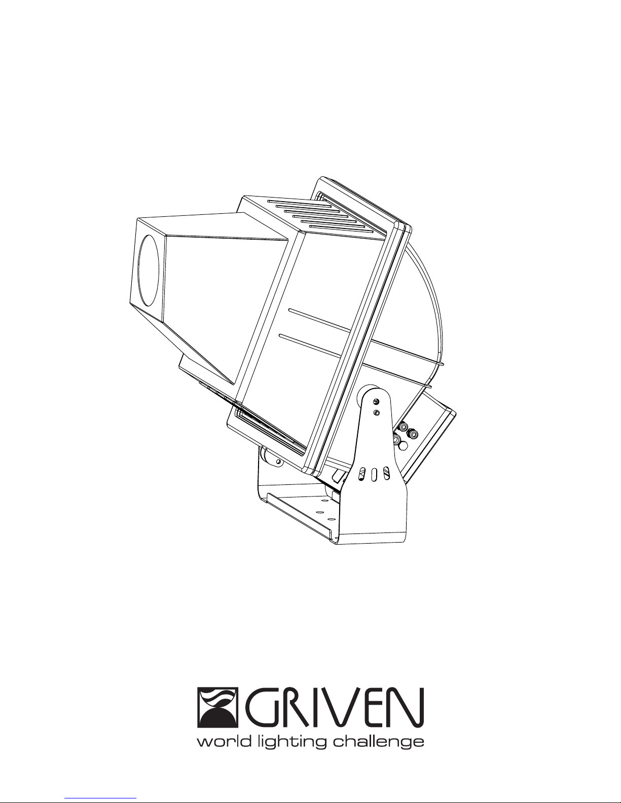
GOBOSTORM PLUS MK2
GR0660
Instruction manual
Page 2

Page 3

INDEX
1.0 Introduction ...................................................................................................................................................................4
1.1 Safety information...................................................................................................................................................................................................4
1.1.1 Protecting against electric shock................................................................................................................................................................4
1.1.2 Installation......................................................................................................................................................................................................4
1.1.3 Protection against burns and fire.................................................................................................................................................................4
1.1.4 Protection against lamp explosion..............................................................................................................................................................4
1.1.5 Weather protection .......................................................................................................................................................................................4
1.1.6 Protection against UV radiation ...................................................................................................................................................................4
1.2 Warranty conditions ...............................................................................................................................................................................................4
1.3 Compliance ............................................................................................................................................................................................................5
2.0 Size .................................................................................................................................................................................5
3.0 Components of the unit................................................................................................................................................6
4.0 Packaging and transport .............................................................................................................................................6
4.1 Packaging ...............................................................................................................................................................................................................6
4.2 Transport ..................................................................................................................................................................................................................6
5.0 Quick turn on.................................................................................................................................................................7
6.0 Installation .....................................................................................................................................................................9
6.1 Fixing........................................................................................................................................................................................................................9
6.2 Adjusting light beam direction............................................................................................................................................................................10
6.3 Connection to mains power................................................................................................................................................................................10
6.4 Connection to DMX signal...................................................................................................................................................................................13
7.0 Lamp installation and replacement..........................................................................................................................15
7.1 Lamp specifications ............................................................................................................................................................................................15
7.2 Lamp installation...................................................................................................................................................................................................15
8.0 Replacing gobos and focus ......................................................................................................................................17
8.1 Replacing gobos ..................................................................................................................................................................................................17
8.2 Focus......................................................................................................................................................................................................................18
8.3 Mounting the optional 16° Angle lens ................................................................................................................................................................18
9.0 Use of the unit..............................................................................................................................................................20
9.1 Setting operating mode .......................................................................................................................................................................................20
9.2 Unit control panel .................................................................................................................................................................................................20
9.2.1 Reading the display and using controls ...................................................................................................................................................20
9.3 DMX Address setting ............................................................................................................................................................................................20
9.4 AUTOMATIC mode................................................................................................................................................................................................21
9.4.1 Programs execution....................................................................................................................................................................................21
9.4.2 Programs setting..........................................................................................................................................................................................21
9.5 Lamp setting..........................................................................................................................................................................................................22
9.6 Utility.......................................................................................................................................................................................................................22
9.7 Software release ...................................................................................................................................................................................................22
10.0 DMX function mode..................................................................................................................................................23
10.1 DMX channels.....................................................................................................................................................................................................23
10.2 DMX functions .....................................................................................................................................................................................................23
10.3 DMX signal interruption ......................................................................................................................................................................................25
10.4 Lamp management by DMX signal..................................................................................................................................................................25
11.0 Master-Slave and Automatic function....................................................................................................................25
11.1 AUTOMATIC configuration .................................................................................................................................................................................25
11.2 MASTER configuration.........................................................................................................................................................................................25
11.3 SLAVE configuration ...........................................................................................................................................................................................25
12.0 RDM function .............................................................................................................................................................26
13.0 Maintenance.............................................................................................................................................................26
13.1 Cleaning the unit ................................................................................................................................................................................................26
13.2 Regular checks...................................................................................................................................................................................................26
13.3 Gears lubrication ................................................................................................................................................................................................27
14.0 Spare parts ................................................................................................................................................................28
15.0 Disposal......................................................................................................................................................................28
16.0 Message errors..........................................................................................................................................................29
17.0 Troubleshooting.........................................................................................................................................................30
18.0 Technical specifications ..........................................................................................................................................30
Page 4
4 English
1.1 Safety information
1.1.1 Protecting against electric shock
• Disconnect the unit from mains supply before servicing it or performing any other action.
• Always ground/earth the unit electrically.
• Before connecting the unit to power supplies, verify that operating voltage and frequency are compatible.
• Do not handle the unit with wet hands or in the presence of water.
• Check regularly that the power supply cable is not damaged or crushed.
• Apply to a qualified technician for any regular maintenance action not described in this manual.
1.1.2 Installation
• Fix the unit with screws, hooks or any other support able to bear the weight of the unit itself.
• If the unit is fixed onto a suspended structure, this structure is supposed to bear at least ten times the weight of
all devices to be fixed.
• The unit installation actions must be performed by a qualified staff.
1.1.3 Protection against burns and fire
• Suitable to be installed onto normally inflammable surfaces.
• If the projector is in a fixed position and the beams is directed towards a flammable surface, the unit should be
kept at a minimum of 1 mt. If the beam is directed to people or thing at a distance lower than 2 mt, please
turn the lamp immediately off.
• The unit is not to be installed in places where the ambient temperature exceeds 35° (95°F).
• The external temperature of the unit surface (front glass) can reach 80°C (176°F).
• The lamp is very hot during operations! Wait at least for 20 minutes before changing.
1.1.4 Protection against lamp explosion
• Please replace any lamp that may present any damage or deformation.
• During the lamp replacement always use adequate body and eye protection (see the lamp manufacturer
instruction)
1.1.5 Weather protection
The unit is classified as device with an IP65 weather protection rate.
1.1.6 Protection against UV radiation
• Never operate the fixture with missing or damaged lenses and / or cover.
• Replace any damaged shields with original GRIVEN spare parts..
• Do not stare directly into the light. Never look at an exposed lamp while it is lit.
1.2 Warranty conditions
• Each product manufactured by GRIVEN srl of Italy is assembled and built in accordance to current CE conformity rules and regulations.
• Every single product and component has been tested before the final assembling and all products must pass
the in-house quality control before they are shipped.
• GRIVEN srl of Italy guarantees the good quality and manufacture of the products and undertakes to repair or
supply again, according to his opinion and free of charge, within the shortest time possible, any part that shows
- during the guarantee period - defects of constructions, manufacture or material.
• The guarantee is valid for 12 (twelve) months starting from the delivery date of the products.
• GRIVEN srl of Italy does not respond for damages occurred to the units during transport and for irrational use and
inaccuracy in regular maintenance of the products.
• The guarantee excludes all consumables.
• The customer will take care of the return of the faulty parts to GRIVEN srl of Italy, at his own charge and risk.
1.0 Introduction
Warning!
This unit is suitable for professional use only, not for domestic use.
Page 5
English 5
• The parts which have been repaired or replaced are sent by GRIVEN srl of Italy ex-factory.
• For any dispute, the Court of Mantova (Italy) will be competent and in conformity with relevant jurisdiction the
Italian Law is enforced for any controversy.
1.3 Compliance
• Product in compliance with EN60598-1 EN60598-2-17.
• Product in compliance with 2002/95/CE (RoHS).
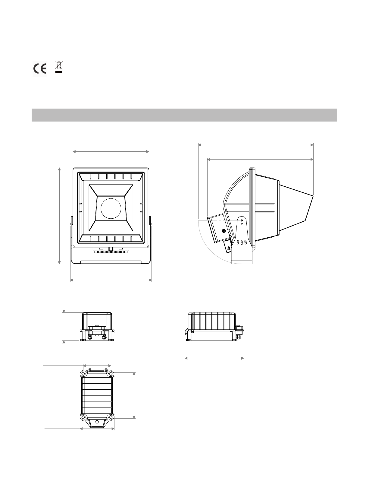
176mm
6,92”
368mm
14,47”
285mm
11,22”
173mm
6,81”
213mm
8,39”
2.0 Size
660mm
25,99”
715mm
28,16”
506mm
19,92”
473mm
18,62”
598mm
23,56”
Page 6
6 English
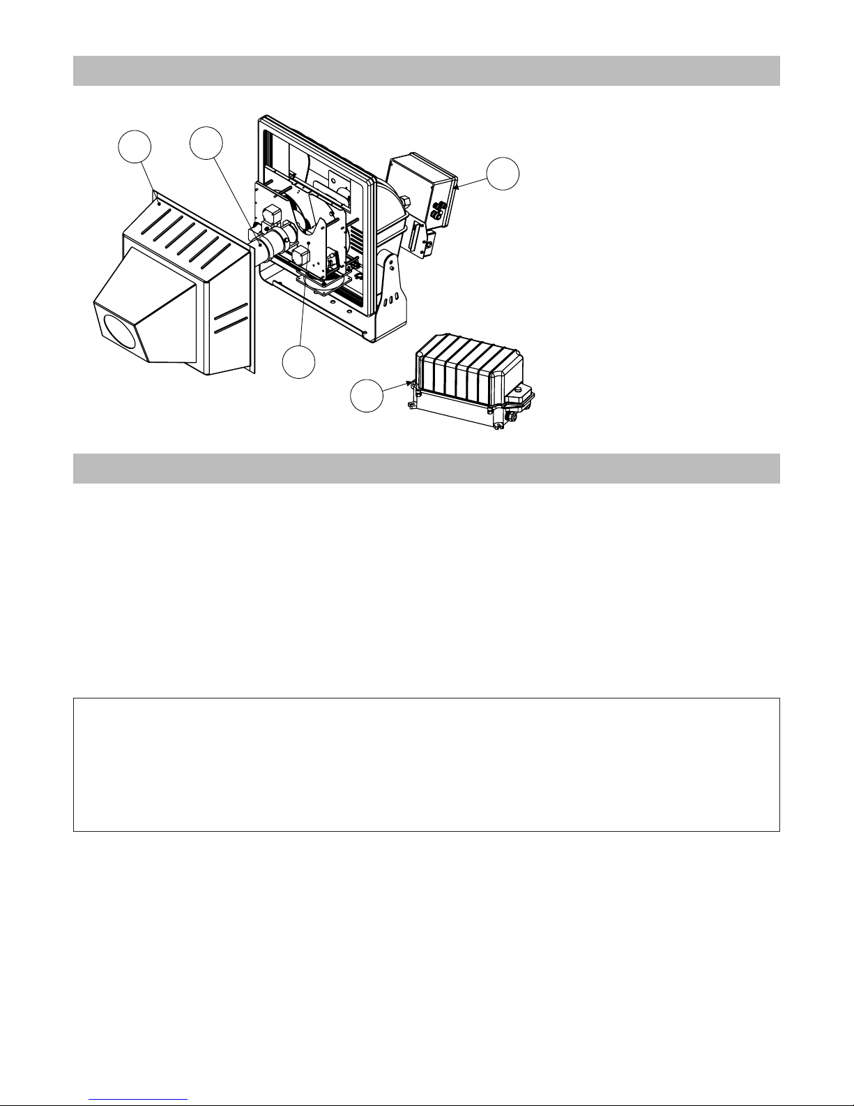
Components description:
A. Front cover
B. Optic group
C. Color and gobos group
D. Electronic box
E. Ballast
4.1 Packaging
Check carefully the content of the box and, in case of damage, contact your forwarder immediately.
The following items are included in the box of this unit:
n° 1 Gobostorm Plus MK2 unit
n° 1 owner’s manual
n° 1 Ballast
n° 2 Connection kit
n° 4 Gobos
n° 4 Spacers 502868 for metal gobos
n° 9 Fixing springs
4.2 Transport
The carton box has not been designed to be used more than once, therefore, it is recommended to use one of
our flight cases to transport the unit.
Warning!
• Griven S.r.l. liability will cease upon consignment of goods to the forwarder: claims for damage due to transport must be addressed directly to the forwarder.
• Griven S.r.l. will accept claims for broken or missing goods only within seven days of receipt of the goods.
• Returns of equipment will not be accepted without prior authorization granted by Griven S.r.l. and if not duly accompanied by relevant shipping documents.
3.0 Components of the unit
A
B
C
D
E
4.0 Packaging and transport
Page 7
English 7
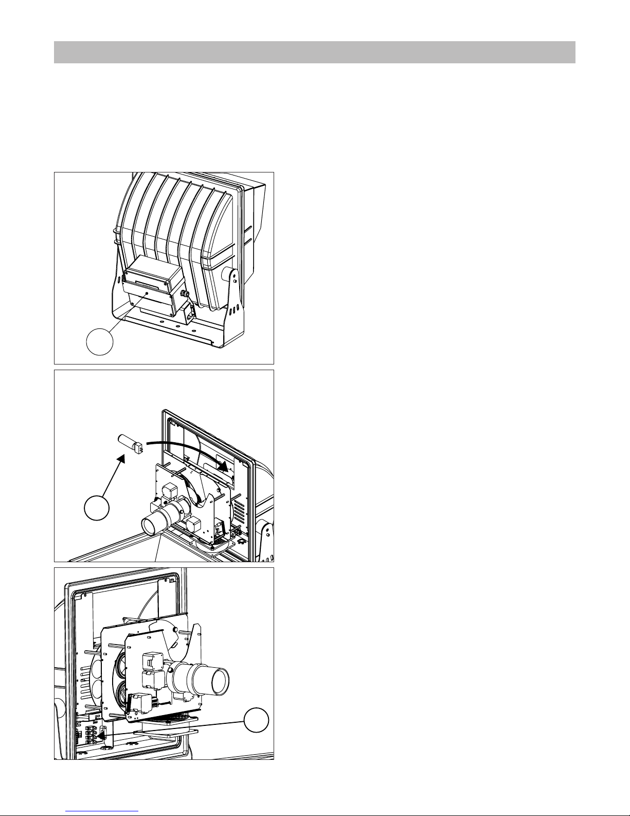
In this chapter brief essential instructions for an immediate use of the unit are listed. These instructions are necessary to connect and power up the unit, but they will not describe in complete details the functions of the unit itself. All other chapters in this manual are therefore supposed to be read, in order to learn all pieces of necessary
information relevant to the unit.
A. Open the box and check the content.
B. Install the unit.
C. Remove the screen protection “1”.
D. Install the lamp “2”.
E. Connect the ballast by using the terminal “3”.
5.0 Quick turn on
1
2
3
Page 8
8 English
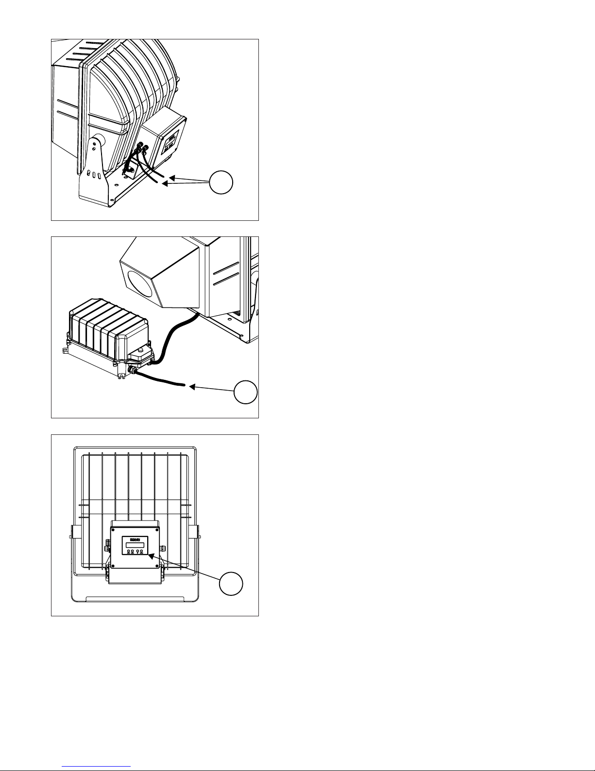
F. Connect the DMX signal by using the cables “4”.
G. Power up the unit by using the cable “5”.
H. Adjust the DMX address and the operating mode by using the
control panel “5” in the rear of the unit.
4
5
6
Page 9
English 9
6.1 Fixing
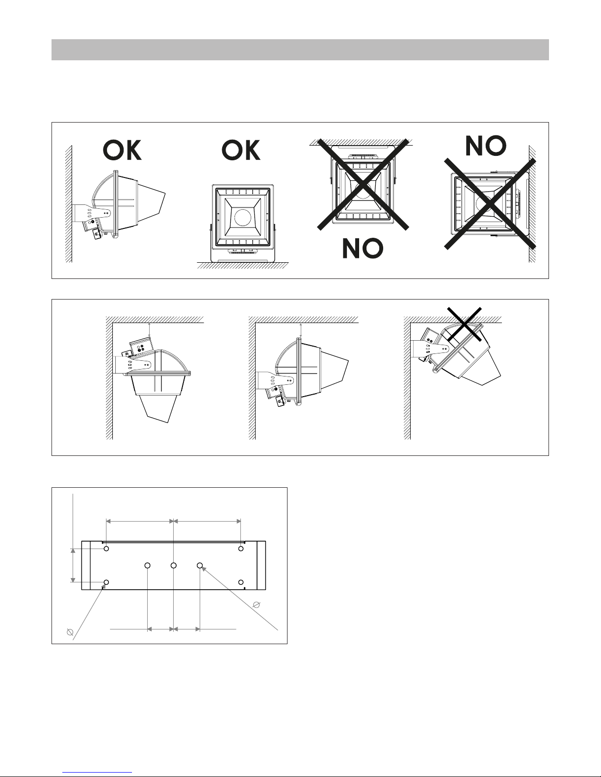
The unit can be used both rested on floor and fixed onto a structure.
Possible mounting positions are shown in the following picture.
Use the holes Ø12.5 and Ø14 in the bracket to fix the unit.
6.0 Installation
Min 10 cm
Min 10 cm
70mm
2,76in
70mm
2,76in
90mm
3,54in
180mm
7,09in
180mm
7,09in
14m
m
0,
55in
12mm
0,4
7in
Page 10
10 English
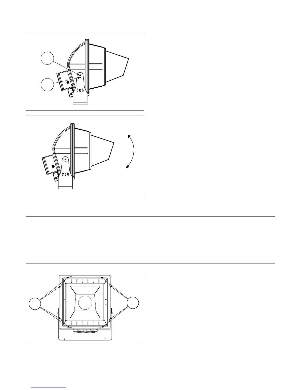
6.2 Adjusting light beam direction
A. Untighten the screws "7" and the grain “8”.
B. Rotate the body of the unit towards desired direction
and tighten the screws “7” and the grain “8”.
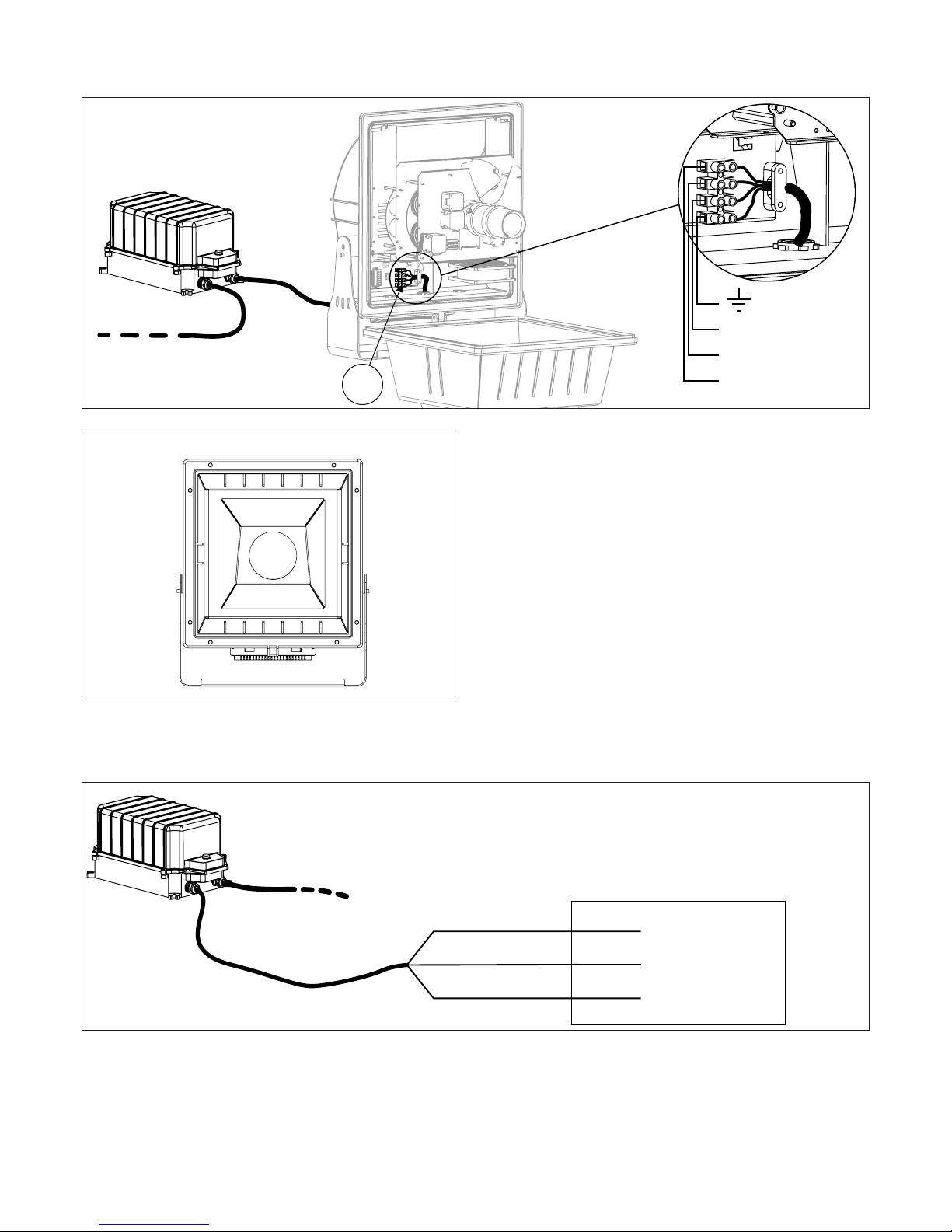
6.3 Connection to mains power
The unit can operate with voltage from 200 to 220Vac or 230 to 240Vac and with frequency of 50 and 60Hz.
A. Untighten the screws “9” ed open the projector.
7
8
Warning!
• Before connecting the unit, verify that power supplies features are compatible with the unit features.
• The unit must never be installed if not grounded electrically.
• It is suggested to use a magnetothermic switch along the power supply line, as prescribed by in force rules.
• The unit must not be powered up through a dimmer power device.
• Wiring and connection actions are to be performed by a qualified staff.
9
9
Page 11
English 11
Connect the ballast by using the terminal “10”.
Close the projector following the numerical order shown in
the picture.
Power up the ballast.
10
Cable n° 3
Cable n° 2
Cable n° 1
Vac IN
1
2
3
4
5
67
8
Live
Ground
Neutral
Brown
Yellow Green
Blue
Main supply
Page 12
12 English
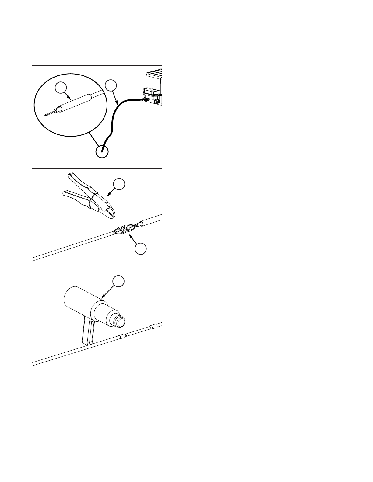
Gobostorm Plus MK2 is fitted with butt connectors and heat shrink tube which allow to perform IP67 connections.
To make the connection follow these instructions.
A. Open the bag with label “POWER SUPPLY”.
You will find inside a piece of heat shrink tube and 4 butt connectors.
B. Insert the tube “12” onto the power supply cable “11” on the
rear box of the unit.
C. Make the connection to the network by using the butt
connectors “14”, pressing them with a proper tool “13”.
D. Warm up the tube by using a heater for heat shrink tubes “15”
till the complete shrinkage.
The connection so obtained features an IP67 protection rate.
12
11
14
13
15
Page 13
English 13
6.4 Connection to DMX signal
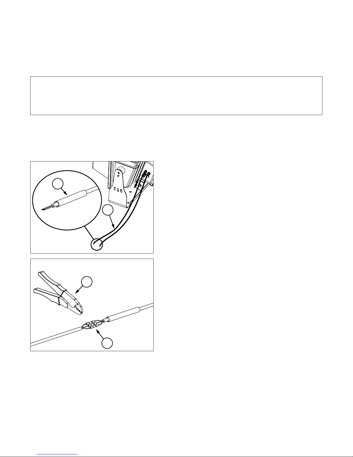
The DMX signal is to be connected by using a shielded cable designed for devices RS-485.
The signal cable must be connected according to the following table:
GND = Hose
DATA - = Black
DATA + = Red
Gobostorm Plus MK2 is fitted with butt connectors and heat shrink tube which allow to perform IP67 connections.
To make the connection follow these instructions.
A. Open the bag with label “DMX”.
You will find inside two pieces of heat shrink tube and 7 butt connectors.
B. Insert the tube “16” onto the dmx cable “17” on the side of
the rear box of the unit.
C. Make the connection to the network by using the butt
connectors “18”, pressing them with a proper tool “19”.
Warning!
All data wires must be isolated one from another and from the shield.
The GND of the DMX signal is not to be connected to the electric ground of the unit.
Insert a terminal plug with a 120 Ω resistor connected to DATA- and DATA+ in the last unit.
16
17
18
19
Page 14
14 English
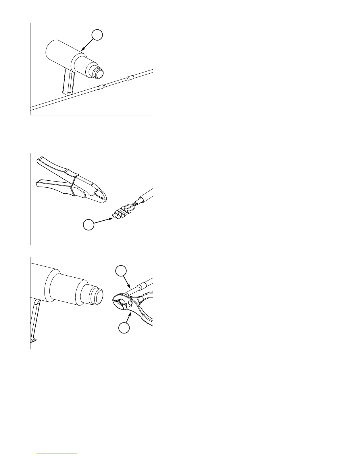
D. Warm up the tube by using a heater for heat shrink tubes “20”
till the complete shrinkage.
The connection so obtained features an IP67 protection rate.
If the unit which you are connecting is the last one of the DMX line, insert a 120 Ω terminal resistor connected
between DATA- and DATA+, as shown and following.
Execute stages “A” and “B”, as previously described.
C. Connect the 120 Ω resistor “21” between DATA- and DATA+
and press the butt connectors by a proper tool.
D. Heat the tube “21” by using a heater for heat shrink tubes till
the complete shrinkage and then press the final end of the
tube with a pincer “22” in order to seal the connection.
20
21
DATA-
DA
TA
+
21
22
Page 15
English 15
7.1 Lamp specifications
Gobostorm Plus MK2 is designed to be used exclusively with Philips MSD 575 or MSR 575 lamp.
The lamps are part of the metal halide family of discharge lamps and must be handled with great care. The lamp
operates at high pressure, and the slight risk of explosion of the lamp exists if operated over its recommended life.
We recommend, therefore, that the lamp is replaced within the manufacturer’s specified lamp life.
Every time the lamp is replaced, please reset the lamplife counter, as described in paragraph 9.5, in order to determine when to perform the next replacement.
The specification of the lamp, available via the Griven network of dealers and distributors, are shown in the table
below.
7.2 Lamp installation
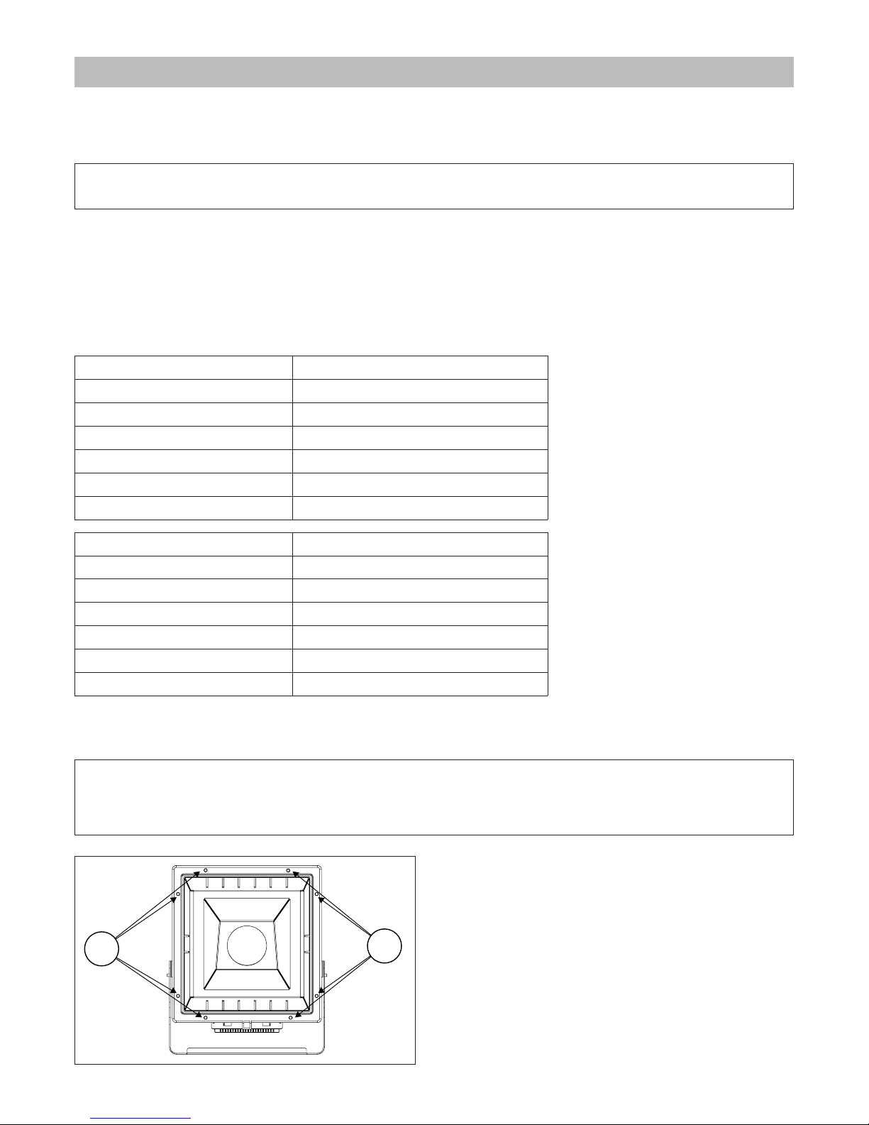
A. Untighten the screws “9” ed open the projector.
7.0 Lamp installation and replacement
Attention!
Installing any other lamp may create a safety hazard or damage the fixture!
Lamp PHILIPS MSD 575
Griven code LP0997
Rated lamp wattage 575W
Colour temperature 5700K ÷ 6000K
Luminous flux 46000 lm
Average service life 2000 h
CRI 75
Lamp PHILIPS MSR 575
Griven code LP0550
Rated lamp wattage 575W
Colour temperature 6990K ÷ 7200K
Luminous flux 49000 lm
Average service life 1000 h
CRI 70
Attention!
Disconnect the unit from mains supply before servicing it or performing any other action.
The lamp is very hot during operations! Wait at least for 20 minutes before changing.
9
9
Page 16
16 English
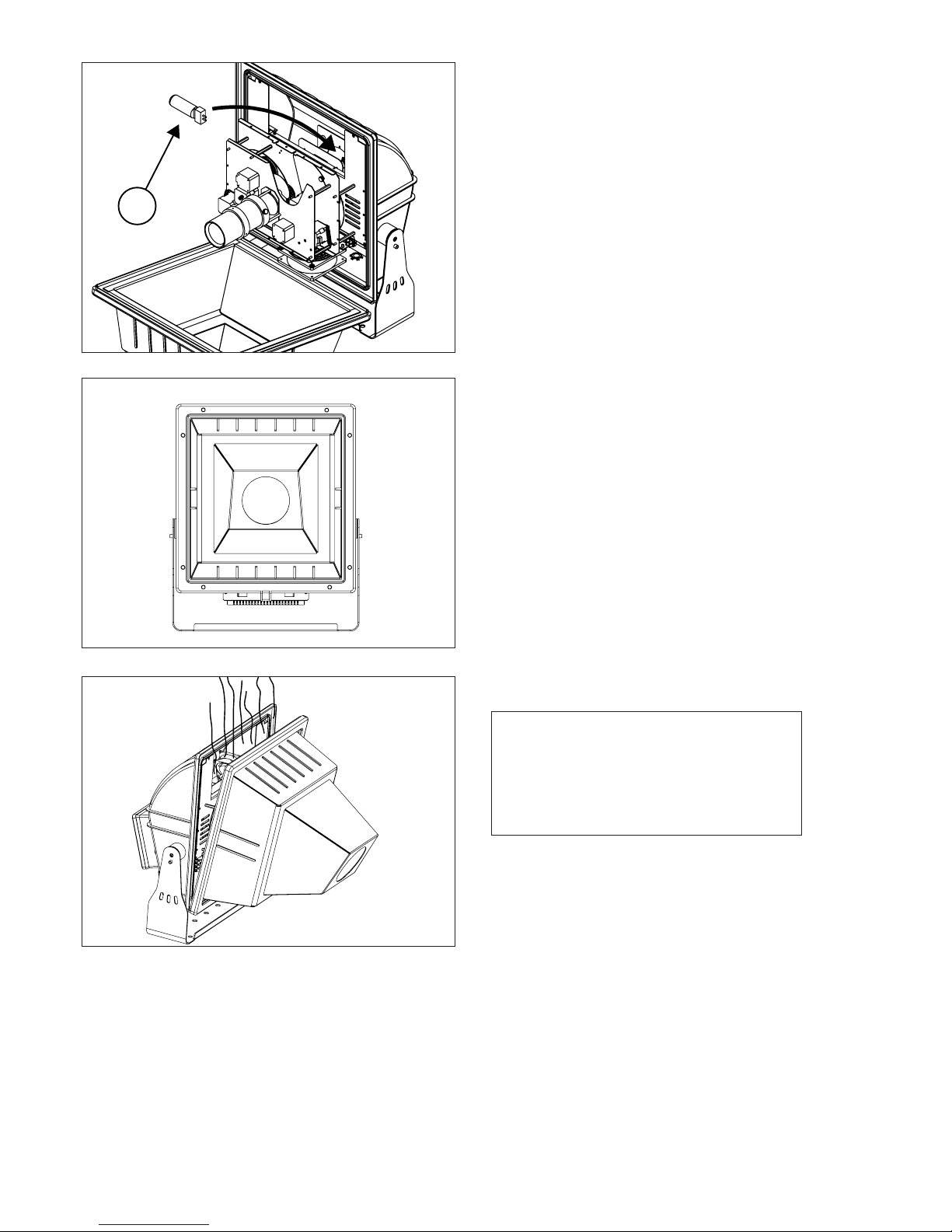
B. Place the lamp “23” transversally.
Close the projector following the numerical order shown in
the picture.
23
1
2
3
4
5
67
8
Attention!
Operate the units with the front panel par-
tially open for 30-40 minutes before clos-
ing them for permanent use.
This precaution will avoid the forming of
condensation in the projector.
Page 17
English 17
8.1 Replacing gobos
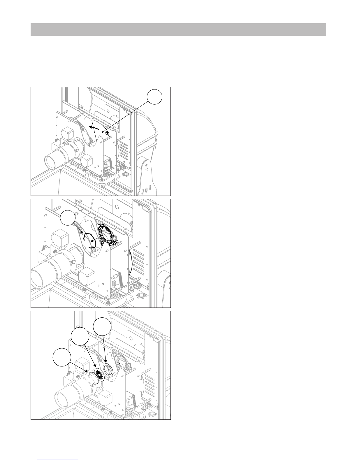
Gobostorm Plus MK2 features a gobos wheel hosting up to 5 gobos (D Size: Ext 53,3 – Int 38).
A. Untighten the screws “9” ed open the projector.
B. Slide the metal plate “24” as shown by the arrow.
C. Remove the fixing ring “25” and proceed with the re-
placement of the gobo.
D. WARNING! The spacer 502868 "27" (provided along with
the fixture) must be placed between the metal gobos
and the gear, as shown in the picture
“25” Fixing ring
“26” METAL gobo
“27” Spacer 502868
E. Re-insert the fixing ring and put back the metal plate “24” in its original position.
24
25
8.0 Replacing gobos and focus
25
27
26
Page 18
18 English
8.2 Focus
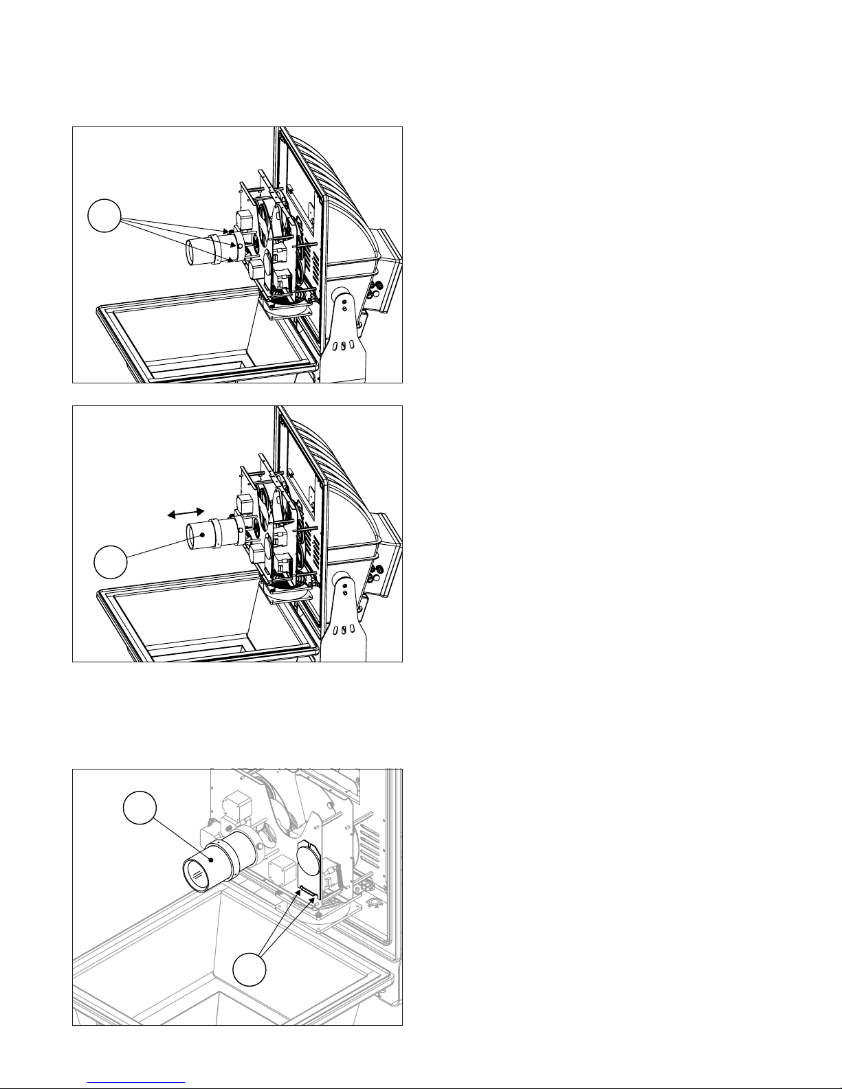
The standard beam angle is 9°. By adjusting the objective it is possible to modify the focusing.
A. Loosen the knobs “28”.
B. Act on the objective “29” to reach the desired focus .
C. Tighten the Knobs “28”.
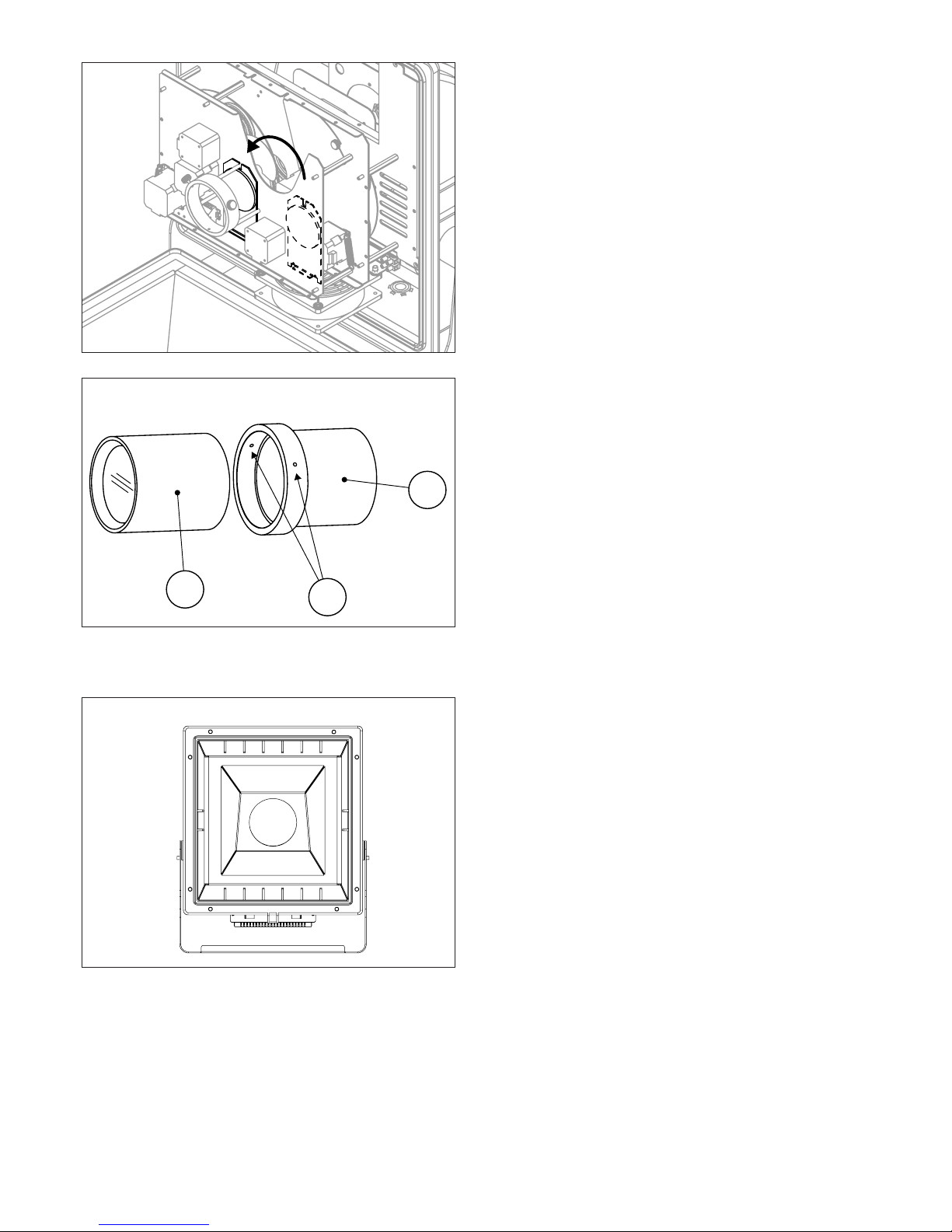
8.3 Mounting the optional 16° Angle lens
By installing the optional lens (provided along with the fixture), the projector will achieve a 16° beam angle.
A. Undo the screws “30”.
B. Remove the objective “31”.
28
29
30
31
Page 19
English 19
C. Place the lens as shown in the picture and secure it
by using the screws previously removed.
D. Loosen the screws “32” and remove the spacer “33”.
E. Install the objective “34” in its seat and perform the focusing.
Close the projector following the numerical order shown in
the picture.
32
33
34
1
2
3
4
5
67
8
Page 20
20 English
9.1 Setting operating mode
By the control panel it is possible to select one of the following operating modes:
• using DMX512 signal control mode
Each fixture is controlled from DMX512 signal control.
(see chapter 10.0 DMX function)
• MASTER-SLAVE or AUTOMATIC mode
The projector operates independently, without DMX512 signal control.
(see chapter 11.0 MASTER/SLAVE and AUTOMATIC function)
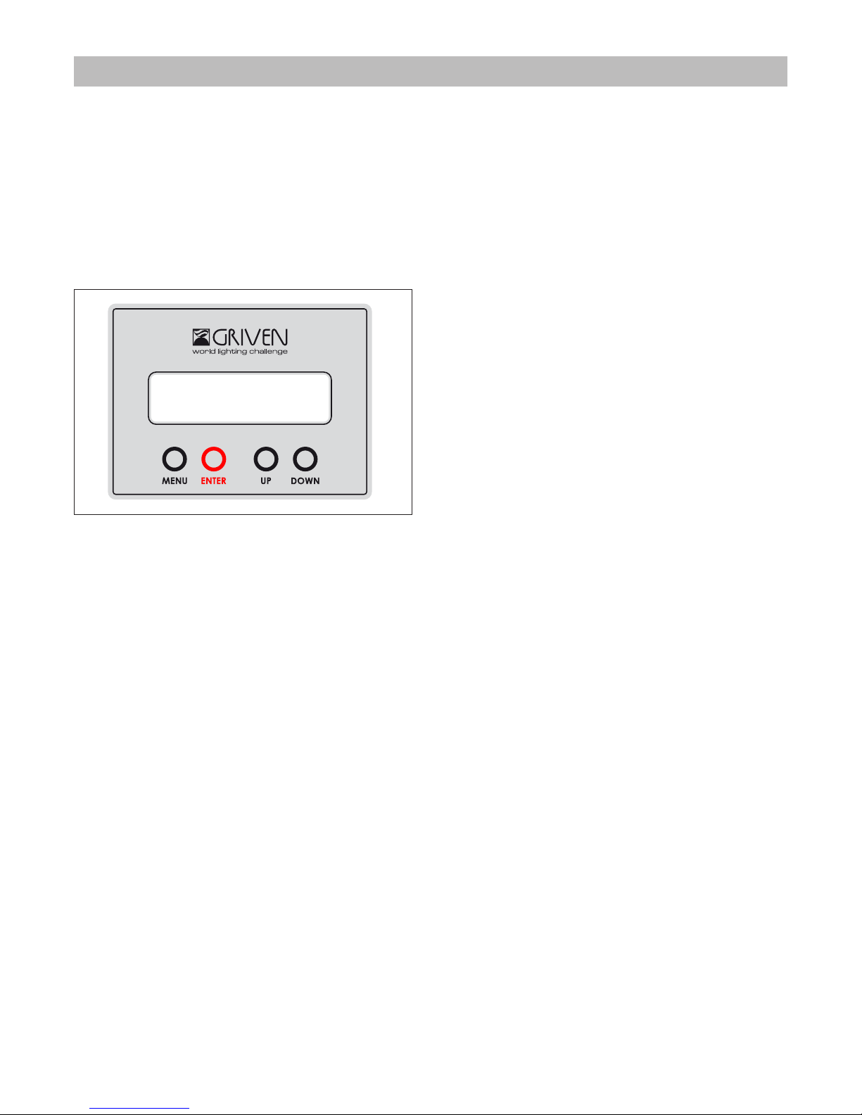
9.2 Unit control panel
After 20 seconds of inactivity, the display will show a message about the projector status. 3 different status can be
shown:
• DMX OFF
• DMX ON
• AUTO ON
9.2.1 Reading the display and using controls
MENU button:
By pushing the “MENU” button the display will show the main menu or you can exit from function and go back to
main menu.
By pushing the “MENU” button when is show the DMX address, you will enter in the main menu.
• ADDRESS SETTING
• AUTOMATIC
• LAMP SETTING
• UTILITY
• RELEASE SOFTWARE
UP and DOWN buttons:
By pushing the “UP” and “DOWN” buttons, values of the function which is shown in the display can be changed.
ENTER button:
Press “ENTER” to select, or to memorize the function which is shown on the display.
9.3 DMX Address setting
When the projector is in “AUTOMATIC” mode the menu “ADDRESS SETTING” is not visible.
Press ENTER when the display shows ADDRESS SETTING.
By using the buttons UP and DOWN select the desired value (ON or OFF) and press ENTER to confirm.
9.0 Use of the unit
Page 21

English 21
9.4 AUTOMATIC mode
Press ENTER when the display shows AUTOMATIC.
This mode allows you to run or to create programs. A maximum number of 4 programs is available; each program
can perform up to 50 scenes.
• PROGRAM 1
• PROGRAM 2
• PROGRAM 3
• PROGRAM 4
• RUN PROGRAMS
9.4.1 Programs execution
Press ENTER when the display shows RUN PROGRAMS.
By selecting “ON” the programs execution is enabled.
By selecting “OFF” the programs execution is disabled.
If the DMX signal is present (Input), it won’t be possible to enable the Automatic Mode and the display will•
show “DMX LINE BUSY
9.4.2 Programs setting
Select, by using the buttons UP and DOWN, the program (from #1 to #4) to be modified/run and then press
ENTER.
You will access a sub-menu with the following options:
• PROGRAMMING
• PLAY
Programs execution “PLAY”:
By selecting ON the programs execution is enabled
By selecting “OFF” the programs execution is disabled
Program settings “PROGRAMMING”:
Select PROGRAMMING by using the buttons UP and DOWN and then pressing ENTER.
By selecting the scene (SCENE 01 SCENE 02…) through the buttons UP and DOWN and then pressing ENTER, you
will access a sub-menu with the following options:
• CREATE / EDIT
If the scene does not exist the display will show CREATE, otherwise EDIT.
By pressing ENTER you will get the programming menu, while pressing MENU you will go back to the previous menu
The display will show the following message:
P1-SCENE 01
CREATE
Where P1 refers to the program and SCENE 01 to the scene to be created.
• DELETE
Select YES or NO through the buttons UP and DOWN to delete the scene
The display will show the following message
P1-SCENE 01
DELETE? NO
If the scene does not exist the display won’t show the option DELETE.
Page 22

22 English
By selecting the scene programming the following functions will be requested in sequence:
Select the DMX value corresponding to the required function. The program number, the scene number and the
function you are programming will appear in the first line. In the second line the DMX value (to be selected through
the UP and DOWN buttons) will be shown.
• Dimmer programming DIMMER
• Color wheel programming COLOR
• Gobo wheel programming GOBO W
• Gobo Rotation programming GOBO ROT.
• Gobo index programming GOBO IDX
• Effects wheel programming EFFECT W
• Effects rotation programming EFFECT ROT
• Effects index programming EFFECT IDX
• ZAP effect programming ZAP
• SHAKE effect programming SHAKE
• Scene time programming TIME (select 1 – 999 sec)
When the scene programming is completed, you will be asked to create or edit/delete the next scene.
9.5 Lamp setting
Press ENTER when the display shows LAMP SETTING.
• MANUAL LAMP ON
Values: ON / OFF
By selecting ON the lamp will always turn on, independently from the DMX value of the channel 1.
By selecting OFF the lamp will be controlled by the DMX channeel 1
• LAMP LIFE
By selecting this function the display will show the lamp life counter.
• RESET LAMP LIFE
Values: YES/NO
By selecting YES the counter will be reset to zero.
9.6 Utility
Press ENTER when the display shows UTILITY.
• DEFAULT SETTING
Values: CANCEL / RESET
It allows you to upload the default settings. RESET will restore the factory settings.
• FIXTURE RESET
Values: CANCEL / RESET
By selcting RESET the fixture will reset all motors. The lamp will remain in its current status
• RESERVED 1
The access to this menu is allowed to GRIVEN engineers only.
• FIXTURE TEST
Values: YES / NO
A test of all the projector functions will be performed; the display will show the test currently underway.
• FIXTURE LIFE
By selecting this function the projector life counter will be shown on the display.
• RESERVED 2
The access to this menu is allowed to GRIVEN engineers only.
9.7 Software release
Press ENTER when the display shows the menu RELEASE SOFTWARE.
The software releases installed (Master, Slave) will be displayed in sequence.
Page 23
English 23
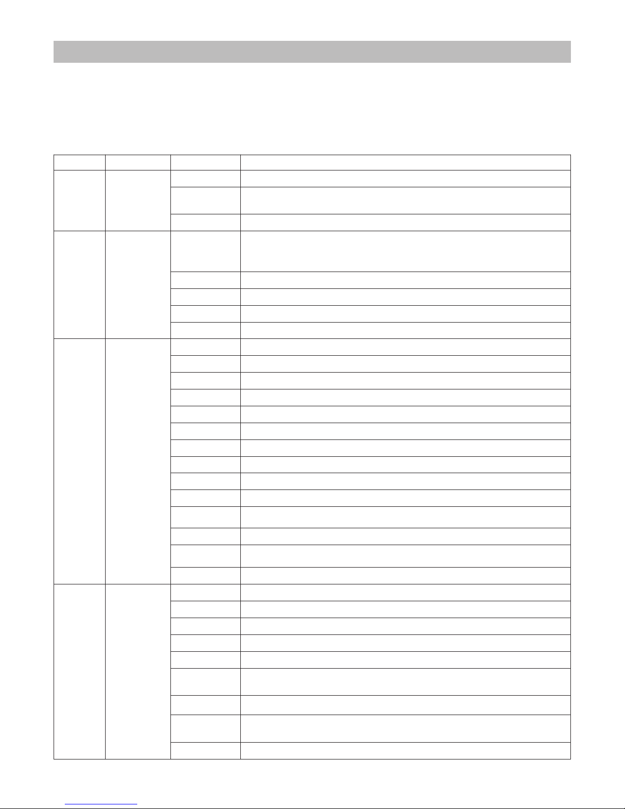
10.1 DMX channels
Each unit use 11 DMX channels.
In case of more units, the first unit will be set with address 001, the second unit with address 0012, the third unit with
address 023, etc.
10.2 DMX functions
10.0 DMX function mode
Channel Function Value Description
1
Lamp
ON/OFF
0-63 Lamp off (OFF) the lamp will switch off after 10 seconds
64-127
Motors reset (the reset will start after 10 seconds) (The lamp remains in
its current status)
128-255 Lamp on (ON)
2
Blackout
Dimmer
Strobo
0-5
Blackout closed (if it remains closed for more than 30 second, any
motor will stop until the next modification of the DMX value of the motors channel).
6-127 0-100% proportional control of the black-out
128-159 Open
160-239 0-100% proportional control of strobe effect
240-255 Open
3 Color wheel
0-10 White
11-20 Yellow
21-30 Orange
31-40 Red
41-50 Violet
51-60 Magenta
61-70 Green
71-80 Cyan
81-90 Blue
91-100 White
101-160
Proportional clockwise rotation (excluding channel 10 for colors repositioning)
161-170 White
171-230
Proportional anticlockwise rotation (excluding channel 10 for colors repositioning)
231-255 White
4
Gobos
selection
0-24 Gobo 1
25-48 Gobo 2
49-72 Gobo 3
73-96 Gobo 4
97-120 Gobo 5
121-180
Proportional clockwise rotation of the wheel (excluding channel 10 for
Gobo repositioning)
181-190 Gobo 1
191-250
Proportional anticlockwise rotation of the wheel (excluding channel
10 for Gobo repositioning)
251-255 Gobo 1
Page 24

24 English
Canale Funzione Valore Descrizione
5
Gobos
rotation
0-15 No effect
16-130 Proportional clockwise control of the rotation
131-140 No effect
141-255 Proportional anticlockwise control of the rotation
6
Gobo
indexing
0-7 No effect
8-248 360° Gobo indexing (excluding channel 5 for gobos rotation)
249-255 No effect
7
Effects
selection
0-24 Effect 1
25-48 Effect 2
49-72 Effect 3
73-96 Effect 4
97-120 Effect 5
121-180
Proportional clockwise rotation of the wheel (excluding channel 10 for
effects repositioning)
181-190 Effect 1
191-250
Proportional anticlockwise rotation of the wheel (excluding channel 10
for effects repositioning)
251-255 Effect 1
8
Effects
rotation
0-15 No effect
16-130 Proportional clockwise control of the rotation
131-140 No effect
141-255 Proportional anticlockwise control of the rotation
9
Effects
indexing
0-7 Nessun effetto
8-248 360° effects indexing
249-255 No effect
10 Zap effect
0-10 No effect
11-80 Proportional ZAP effect with opening and closing at the same speed
81-90 No effect
91-160 Proportional ZAP effect with slow closing and quick opening
161-170 No effect
171-240 Proportional ZAP effect with quick closing and slow opening
241-255 No effect
11 Shake effect
0-10 No effect
11-80 Proportional shake effect on Gobos
81-90 No effect
91-160 Proportional shake effect on effects
161-170 No effect
171-240 Shake effect on Gobos and effects
241-255 No effect
Page 25
English 25
10.3 DMX signal interruption
If the DMX signal is absent the shutter will close and the motors will stop in 5 minutes from the last signal reception.
10.4 Lamp management by DMX signal
In the presence of DMX, the lamp is controlled by the 1st channel dmx.
To turn off the lamp via DMX you need to stay at least 4 seconds in the 0-63 area of the DMX channel 1.
To turn on the lamp, allow at least 20 s after switching off.
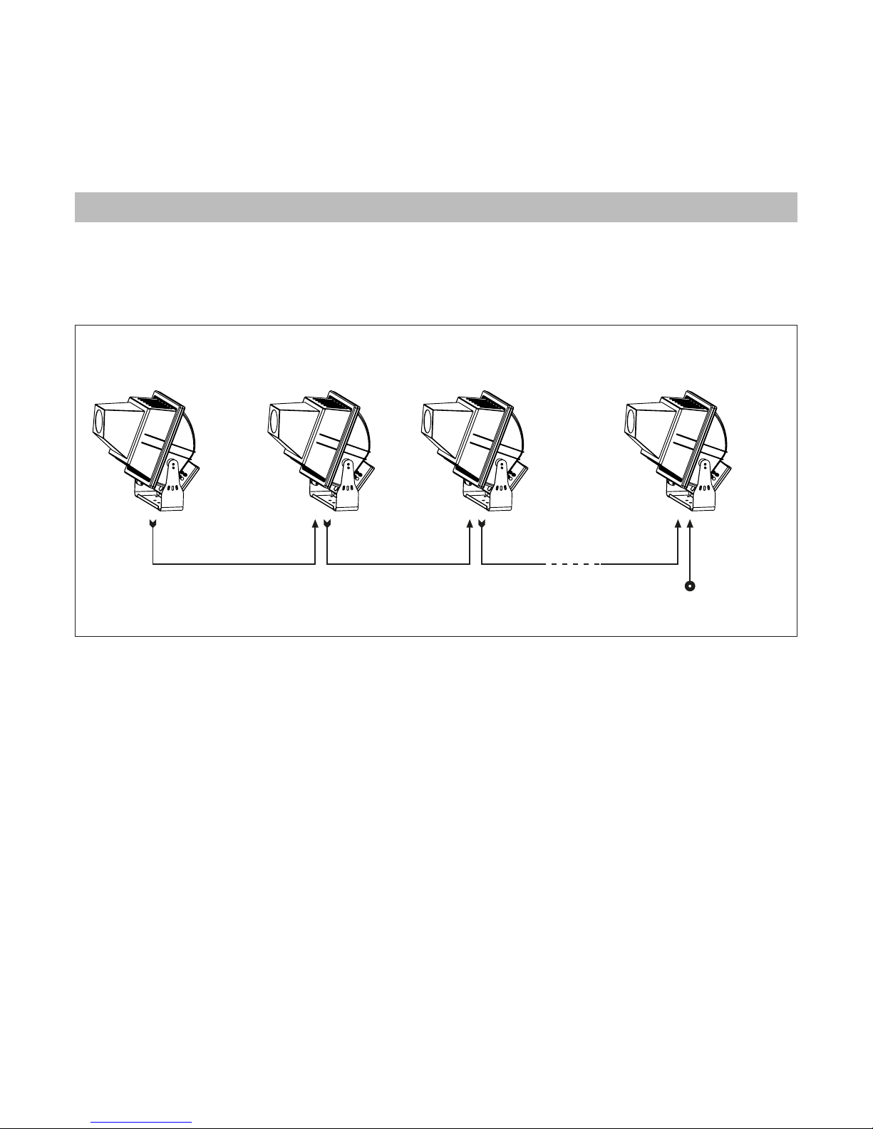
Gobostorm Plus MK2 can operate without DMX signal (in AUTOMATIC mode) and can be set so that a single
MASTER unit will command a series of SLAVE units. This function is particularly useful when more units are desired
to execute the same programme in synchrony.
The following picture shows an example of a Master-Slave layout.
11.1 AUTOMATIC configuration
See paragraph 9.4 AUTOMATIC configuration.
11.2 MASTER configuration
To set up the unit as MASTER the same instructions for the set up as AUTOMATIC must be followed (see paragraph
9.4 AUTOMATIC configuration).
11.3 SLAVE configuration
To set up the unit as SLAVE set the DMX address 001. See paragraph 9.3 DMX setting
11.0 Master-Slave and Automatic function
MASTER SLAVE 1 SLAVE N
INOUTINOUT
SLAVE 2
INOUT
Terminal resistor
(R=120 ƺ not included!)
Page 26
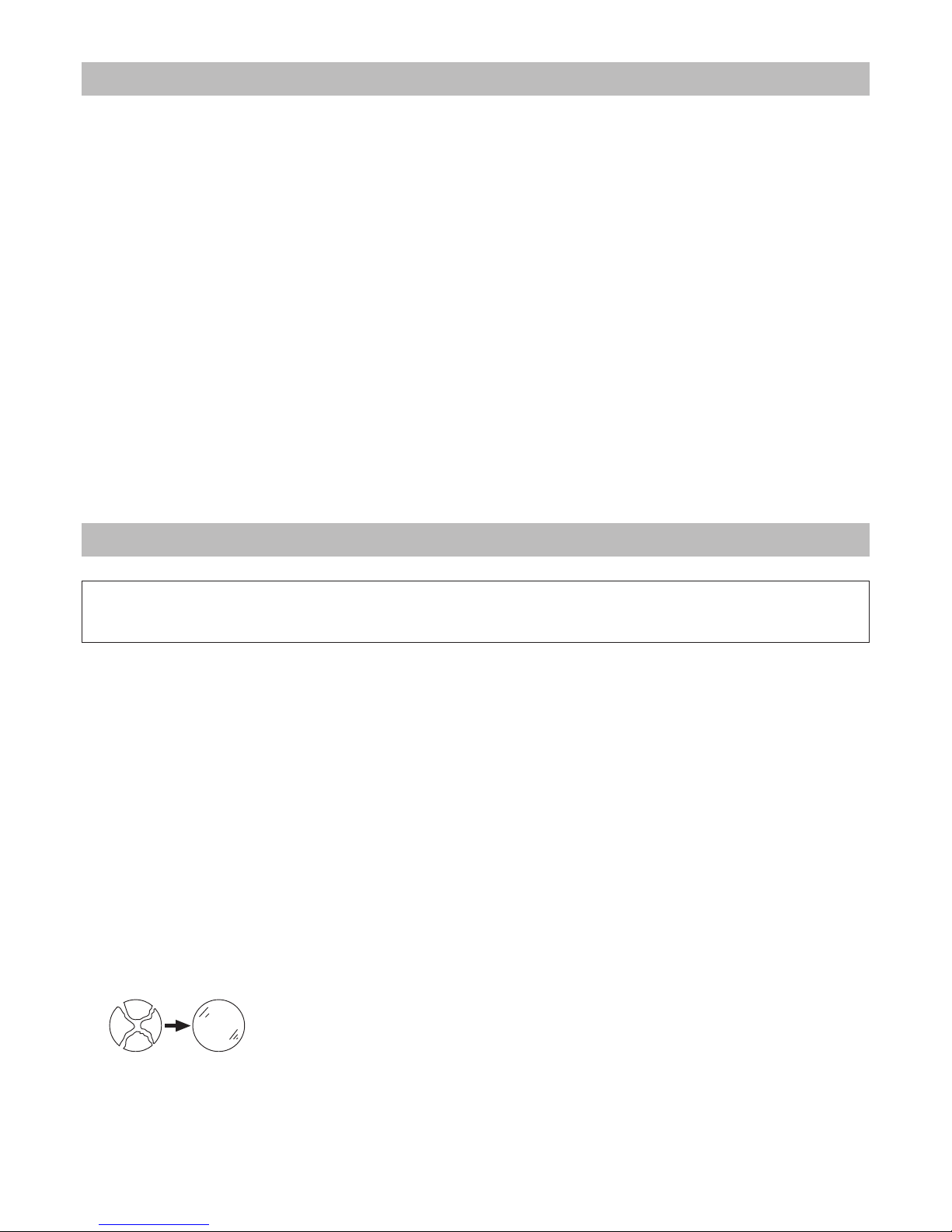
When operating in DMX mode, the projector can accept the following RDM commands:
• discovery
Upon request of the RDM controller, the projector adverts its own presence (the RDM controller will display the
projector between a list).
• DMX address reading and setting.
• Channels number reading
• On / Off identification
This command is used to identify the projector you want to get access to (the identification happens by switching on strobe effect).
• Manufacturer
The name of the manufacturer (Griven) is displayed.
• Model description
The projector model (Gobostorm Plus MK2) is displayed.
• Software version description
The version of the master firmware in use on the projector (Gobostorm Plus MK2 v.x.xx) is displayed.
• Display hours of lamp life
This displays the value of the hours of lamp life.
• Display projector working life hours
This displays the value of the hours of the life of the projector.
• Alarm display
Displayed alarm active on the projector.
To ensure maximum functionality and light output it is recommended to follow these instructions:
13.1 Cleaning the unit
The unit must be cleaned regularly. Cleaning regularity will depend especially on the environment where the unit
will operate: deposits of dust, smokes or other wastes will reduce the light output performances.
• Clean regularly the glass and the mirror of the unit.
• Be careful when cleaning the components. Operate in a clean, properly illuminated environment.
• Do not use solvents which could damage painted surfaces.
• Remove left particles by a cotton towel dampened with a glass-cleaning liquid or distilled water.
• Dry out by a clean, soft, non-scratching towel or by compressed air.
13.2 Regular checks
• Check electrical connections, especially the ground wiring and the power supply cable.
• Check that the unit is not damaged mechanically. Replace those components which have got deteriorated.
• Replace the lenses, the mirrors and the dichroic filters if they are visibly damaged.
• Replace any lamp that may present any damage or deformation.We recommend, therefore, that the lamp be
replaced within the manufacturer’s specified lamp life.
Replace any damaged shield.
12.0 RDM function
13.0 Maintenance
Attention!
Always remove mains power prior to opening up the fixture.
26 English
Page 27
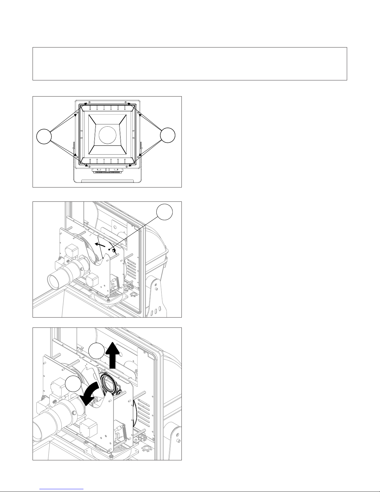
13.3 Gears lubrication
If the rotation of the Gobos or prisms is not smooth and linear, the gears must be lubricated.
A. Untighten the screws “9” ed open the projector.
B. Slide the metal plate “24” as shown by the arrow.
C. Remove the Gobo holder slightly pulling it first outward
and then upward.
Warning!
the gears must be exclusively lubricated with perfluoropolyether UNIFLOR™ 8470 also available through •
GRIVEN authorized dealers network.
This procedure must be exclusively performed by authorized and qualified staff.•
9
9
24
1
2
English 27
Page 28
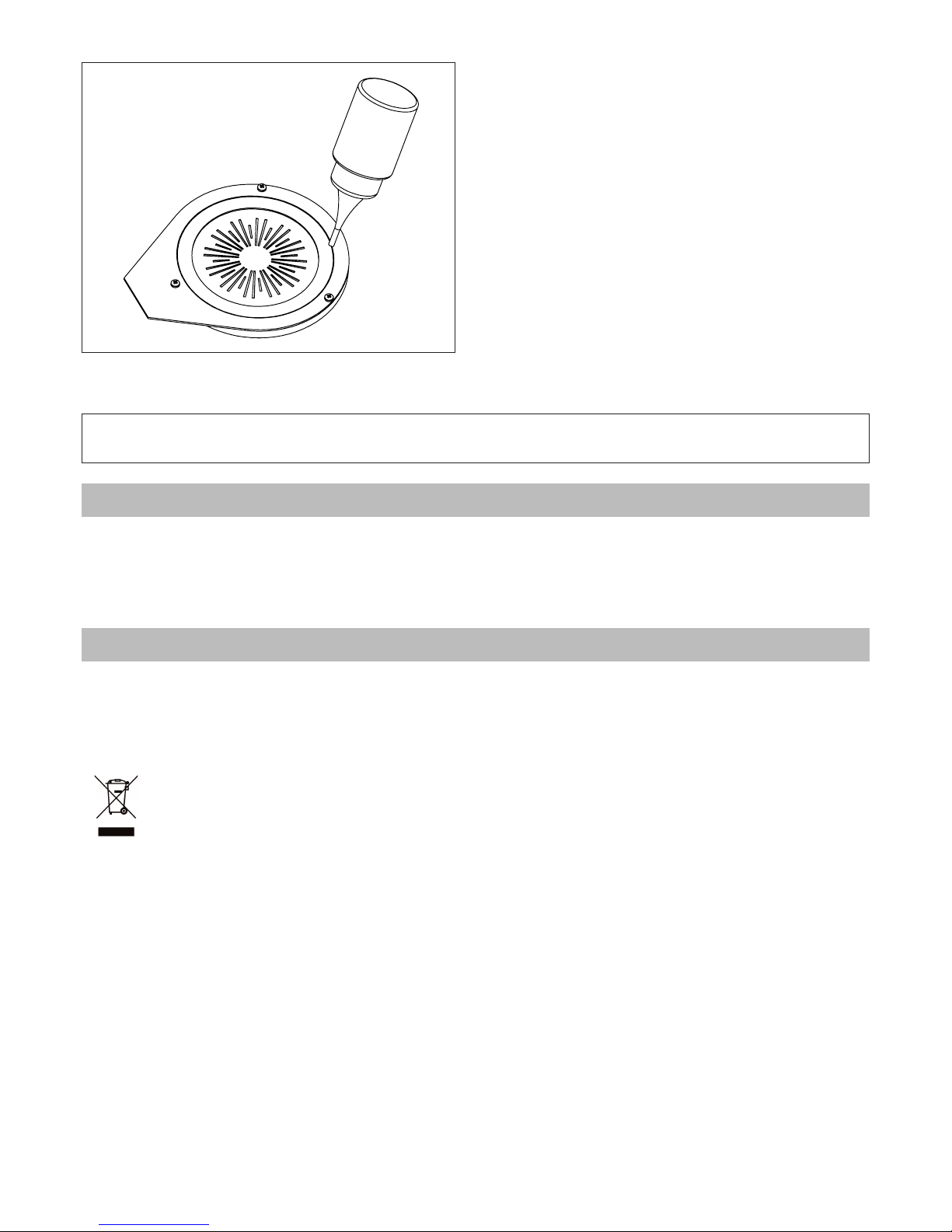
B. Lubricate the fissure between the gobo holder and the
gear as shown in the picture.
C. Re-insert the gobo holder in the wheel
All components of the unit are available as spare parts at Griven dealers.
Exploded views, wiring diagrams, electronic layouts and advertising brochures are available on request.
To make the job of assistance centres easier, specify serial number and model of the unit which spare parts are
requested for.
The European Directive 2002/96/EC on Waste Electrical and Electronic Equipment (WEEE), requires that old
lighting fixtures must not be disposed of the normal unsorted municipal waste stream. Old appliances must be
collected separately in order to optimise the recovery and recycling of the materials they contain and reduce
the impact on human health and the environment.
The crossed out “wheeled bin” symbol on the product reminds you of your obligation, that when you
dispose of the appliance it the must be separately collected.
Consumer should contact their local authority or retailer for information concerning the correct
disposal of their old appliance.
14.0 Spare parts
15.0 Disposal
Warning!
The gobo holder must perfectly adhere to the Gobo wheel.
28 English
Page 29
The unit display can point out faulty functionings by visualizing error codes. Such a visualization is possible only
when the display is at rest condition (visualization of the dmx address).
Message Description Projector’s action
SLAVE COMM. ERROR
Communication with slave microprocessor interrupted.
Motors set to zero. Lamp
turns off. the alarm will subside if communication restarts working properly.
GOBO WHEEL ERROR Gobo wheel sensor. The reset failed None
GOBO INDEXING
ERROR
Gobo rotation sensor. The reset failed None
EFFECT WHEEL ERROR Effects wheel sensor. The reset failed None
EFFECT INDEXING
ERROR
Effects rotation sensor. The reset failed. None
COLOR WHEEL ERROR Color wheel sensor. The reset failed None
IGNITION ERROR The lamp, after several attempts, did not switch on None
OVERHEATING The internal temperature of the projector is too high.
The lamp will be switched
off until the projector has
completed its cooling process.
HEATING The internal temperature of the projector is too low.
No program will be executed until the projector reaches its working
temperature.
16.0 Message errors
English 29
Page 30
Projector mechanical features
Height . . . . . . . . . . . . . . . . . . . . . . . . . . . . . . . . . . . . . . . . . . . . . . . . . . . . . . . . . . . . . . . . . . . . . . . . . . . . . . .598m (23.56”)
Width . . . . . . . . . . . . . . . . . . . . . . . . . . . . . . . . . . . . . . . . . . . . . . . . . . . . . . . . . . . . . . . . . . . . . . . . . . . . . .506mm (19.92”)
Depth . . . . . . . . . . . . . . . . . . . . . . . . . . . . . . . . . . . . . . . . . . . . . . . . . . . . . . . . . . . . . . . . . . . . . . . . . . . . . . . .660mm (26“)
Weight . . . . . . . . . . . . . . . . . . . . . . . . . . . . . . . . . . . . . . . . . . . . . . . . . . . . . . . . . . . . . . . . . . . . . . . . . . . . . . . .24Kg (53Lbs)
Ballast mechanical features
Height . . . . . . . . . . . . . . . . . . . . . . . . . . . . . . . . . . . . . . . . . . . . . . . . . . . . . . . . . . . . . . . . . . . . . . . . . . . . . .176mm (6.92”)
Width . . . . . . . . . . . . . . . . . . . . . . . . . . . . . . . . . . . . . . . . . . . . . . . . . . . . . . . . . . . . . . . . . . . . . . . . . . . . . . .213mm (8.39“)
Depth . . . . . . . . . . . . . . . . . . . . . . . . . . . . . . . . . . . . . . . . . . . . . . . . . . . . . . . . . . . . . . . . . . . . . . . . . . . . . . . . .368 (14.47”)
Weight . . . . . . . . . . . . . . . . . . . . . . . . . . . . . . . . . . . . . . . . . . . . . . . . . . . . . . . . . . . . . . . . . . . . . . . . . . . . . . .10Kg (22 Lbs)
Thermal features
Maximum ambient temperature . . . . . . . . . . . . . . . . . . . . . . . . . . . . . . . . . . . . . . . . . . . . . . . . . . . . . . . . . . .35°C (95°F)
Minimum ambient temperature . . . . . . . . . . . . . . . . . . . . . . . . . . . . . . . . . . . . . . . . . . . . . . . . . . . . . . . . . .-40°C (-40°F)
Maximum surface temperature . . . . . . . . . . . . . . . . . . . . . . . . . . . . . . . . . . . . . . . . . . . . . . . . . . . . . . . . . .100°C (176°F)
Thermal protection . . . . . . . . . . . . . . . . . . . . . . . . . . . . . . . . . . . . . . . . . . . . . . . . . . . . . . . . . . . . . . . . . . . . . . . Electronic
Electrical features
Voltage . . . . . . . . . . . . . . . . . . . . . . . . . . . . . . . . . . . . . . . . . . . . . . . . . . . . . . . . . . .200-220Vac or 230-240Vac 50/60Hz
Nominal current . . . . . . . . . . . . . . . . . . . . . . . . . . . . . . . . . . . . . . . . . . . . . . . . . . . . . . . . . . . 3.9A @ 230V / 5.6A @ 208V
Maximum power . . . . . . . . . . . . . . . . . . . . . . . . . . . . . . . . . . . . . . . . . . . . . . . . . . . . . . . . 656W @ 230V / 820W @ 208V
Light output source
Lamp . . . . . . . . . . . . . . . . . . . . . . . . . . . . . . . . . . . . . . . . . . . . . . . . . . . . . . . . . . . . . . . . . . . . . . . . .575W discharge lamp
Approved models . . . . . . . . . . . . . . . . . . . . . . . . . . . . . . . . . . . . . . . . . . . . . . . . . . . . . . . . . . . . PHILIPS MSD/MSR 575 W
Optics
Optical system . . . . . . . . . . . . . . . . . . . . . . . . . . . . . . . . . . . . . . . . . . . . . . . . . . . . . . . . . . . . . . . . . . . . . . . . . . . . . Lenses
Control
Protocol . . . . . . . . . . . . . . . . . . . . . . . . . . . . . . . . . . . . . . . . . . . . . . . . . . . . . . . . . . . . . . . . . . . . . . . . . . . . . USITT DMX-512
Control channel . . . . . . . . . . . . . . . . . . . . . . . . . . . . . . . . . . . . . . . . . . . . . . . . . . . . . . . . . . . . . . . . . . . . . . . . 11 channels
Construction
Unit body . . . . . . . . . . . . . . . . . . . . . . . . . . . . . . . . . . . . . . . . . . . . . . . . . . . . . . . . . . . . . . . . . . . . . . . . . . . Iron/Aluminium
Treatment . . . . . . . . . . . . . . . . . . . . . . . . . . . . . . . . . . . . . . . . . . . . . . . . . . . . . . . . . . . . . . . Scratch resistant black paint
Weather protection rate . . . . . . . . . . . . . . . . . . . . . . . . . . . . . . . . . . . . . . . . . . . . . . . . . . . . . . . . . . . . . . . . . . . . . . . IP65
17.0 Troubleshooting
Inconvenience Possibile Cause Action
The fixture is completely dead
No power to fixture.
Check that power is switched on and cables are
plugged in.
The unit does not
respond properly
to the DMX control.
Incorrect DMX cable
connection.
Check connections and wires. Rectify inefficient
connections. Repair or replace damaged wires.
Unfinished data
connection.
Insert a terminal plug in the output jack of the last unit of
the connection.
Incorrect address
assignment to the units.
Check the addresses of the units and the protocol
settings.
One of the unit is faulty
and it is affecting the
data transmission along
the connection.
Short-circuit units singularly, one by one, since regular
working is restored.
No light output
Lamp blown Disconnect fixture and replace lamp.
Lamp not installed Disconnect fixture and install lamp.
Blackout closed Verify the DMX channels value
Lamp cuts out
intermittently.
Fixture is too hot.
Let the fixture cool down.
Ensure that the ambient temperature is below 40 °C.
18.0 Technical specifications
30 English
Page 31

NOTES
English 31
Page 32

Via Bulgaria, 16 - 46042 CASTEL GOFFREDO (MN) - Italy
Telefono 0376/779483 - Fax 0376/779682 - 0376/779552
http://www.griven.com/ e-mail [email protected]
http://www.griven.it/ e-mail [email protected]
User’s manual rel. 1.30
 Loading...