

GoboLED 80 D
AL2502
Manuale di istruzioni
Instructions manual

INDEX
1.0 Introduction .................................................................................................................................20
1.1 Safety information.......................................................................................................................................................20
1.1.1 Protecting against electric shock ..........................................................................................................................20
1.1.2 Installation ................................................................................................................................................................20
1.1.3 Protection against burns and fire ...........................................................................................................................20
1.1.4 Weather protection..................................................................................................................................................20
1.1.5 Forced ventilation ....................................................................................................................................................20
1.2 Compliance ................................................................................................................................................................20
2.0 Size ...............................................................................................................................................21
3.0 Packaging and transport ...........................................................................................................21
3.1 Packaging ...................................................................................................................................................................21
3.2 Transport ......................................................................................................................................................................21
4.0 Installation ...................................................................................................................................22
4.1 Fixing ............................................................................................................................................................................22
4.2 Adjusting light beam direction..................................................................................................................................22
4.3 Connection to mains power ......................................................................................................................................23
4.4 Connection to DMX signal .........................................................................................................................................24
4.5 Gobo installation.........................................................................................................................................................25
4.6 Focus and zoom..........................................................................................................................................................27
5.0 Use of the unit..............................................................................................................................28
5.1 Setting operating mode .............................................................................................................................................28
5.2 Setting DMX address...................................................................................................................................................28
5.3 DMX functions .............................................................................................................................................................29
5.3.1 DMX functions in CH mode = 1...............................................................................................................................29
5.3.2 DMX functions in CH mode = 2...............................................................................................................................30
5.3.3 DMX functions in CH mode = 3...............................................................................................................................30
5.3.4 DMX functions in CH mode = 4...............................................................................................................................30
6.0 Master-Slave and Automatic function......................................................................................31
6.1 MASTER configuration.................................................................................................................................................31
6.2 SLAVE configuration....................................................................................................................................................32
6.3 AUTOMATIC configuration .........................................................................................................................................32
7.0 Thermal protection .....................................................................................................................33
8.0 Maintenance...............................................................................................................................33
8.1 Cleaning the unit ........................................................................................................................................................33
8.1.1 Fixture body..............................................................................................................................................................33
8.1.2 Fans and air passages.............................................................................................................................................33
8.2 Regular checks ...........................................................................................................................................................33
9.0 Spare parts ..................................................................................................................................33
10.0 Troubleshooting.........................................................................................................................34
11.0 Disposal......................................................................................................................................35
12.0 Technical specifications ..........................................................................................................35
1.1 Safety information
1.1.1 Protecting against electric shock
• Disconnect the unit from mains supply before servicing it or performing any other action.
• Always ground/earth the unit electrically.
• Before connecting the unit to power supplies, verify that operating voltage and frequency are compatible.
• Do not handle the unit with wet hands or in the presence of water.
• Check regularly that the power supply cable is not damaged or crushed.
• Apply to a qualified technician for any regular maintenance action not described in this manual.
1.1.2 Installation
• Fix the unit with screws, hooks or any other support able to bear the weight of the unit itself.
• The unit installation actions must be performed by a qualified staff.
1.1.3 Protection against burns and fire
• Suitable to be installed onto normally inflammable surfaces.
• Damaged fuses are always to be replaced with working fuses as per type and rate specified.
• The unit is not to be installed in places where the ambient temperature exceeds 40° (104°F).
1.1.4 Weather protection
The unit is classified as device with an IP65 weather protection rate.
The cooling system is classified as device with an IP55 weather protection rate.
1.1.5 Forced ventilation
You will note several air vents on the body of the projector. To avoid any problems associated with overheating,
clean air vent periodically.
1.2 Compliance
• Product in compliance with EN60598-1 EN60598-2-17.
• Product in compliance with 2002/95/CE (RoHS).
1.0 Introduction
Warning!
This unit is suitable for professional use only, not for domestic use.
20 English
3.1 Packaging
Check carefully the content of the box and, in case of damage, contact your forwarder immediately. The following items are included in the box of this unit:
n° 1 Goboled 80 D unit
n° 1 owner’s manual
3.2 Transport
The carton box has not been designed to be used more than once, therefore, it is recommended to use one of
our flight cases to transport the unit.
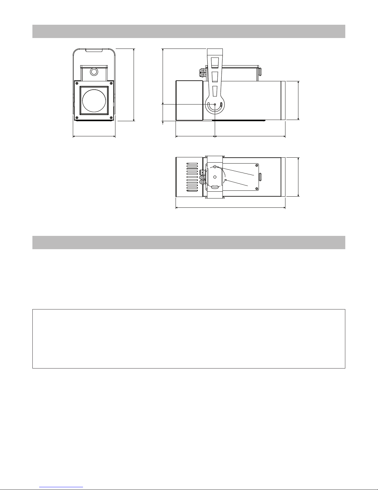
2.0 Size
280.5mm
11"
216mm
8.5"
150.3mm
5.9"
150.3mm
5.9"
64.5mm
2.5"
164mm
6.5"
152mm
6"
273mm
10.8"
425.3mm
16.7"
Ø
80
m
m
3.
2”
Ø
1
0
.
5
m
m
0
.
4
”
3.0 Packaging and transport
Warning!
• Griven S.r.l. liability will cease upon consignment of goods to the forwarder: claims for damage due to transport must be addressed directly to the forwarder.
• Griven S.r.l. will accept claims for broken or missing goods only within seven days of receipt of the goods.
• Returns of equipment will not be accepted without prior authorization granted by Griven S.r.l. and if not duly accompanied by relevant shipping documents.
English 21
22 English
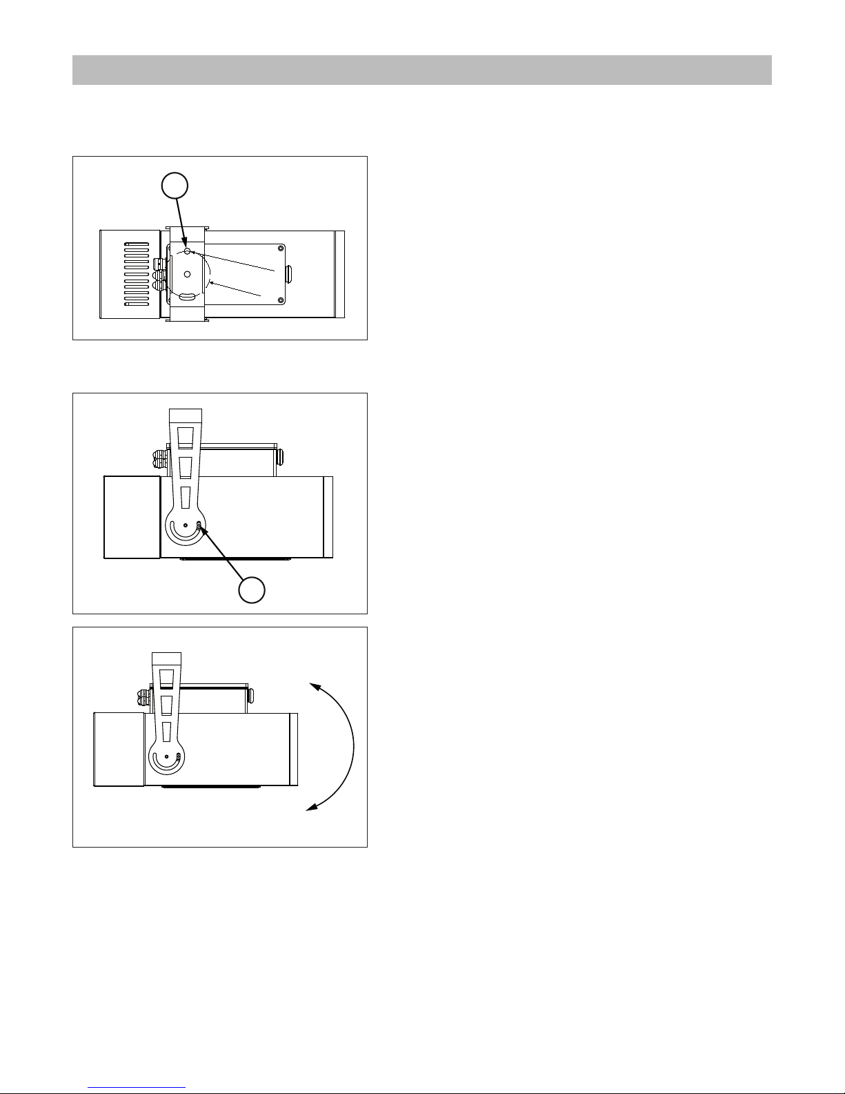
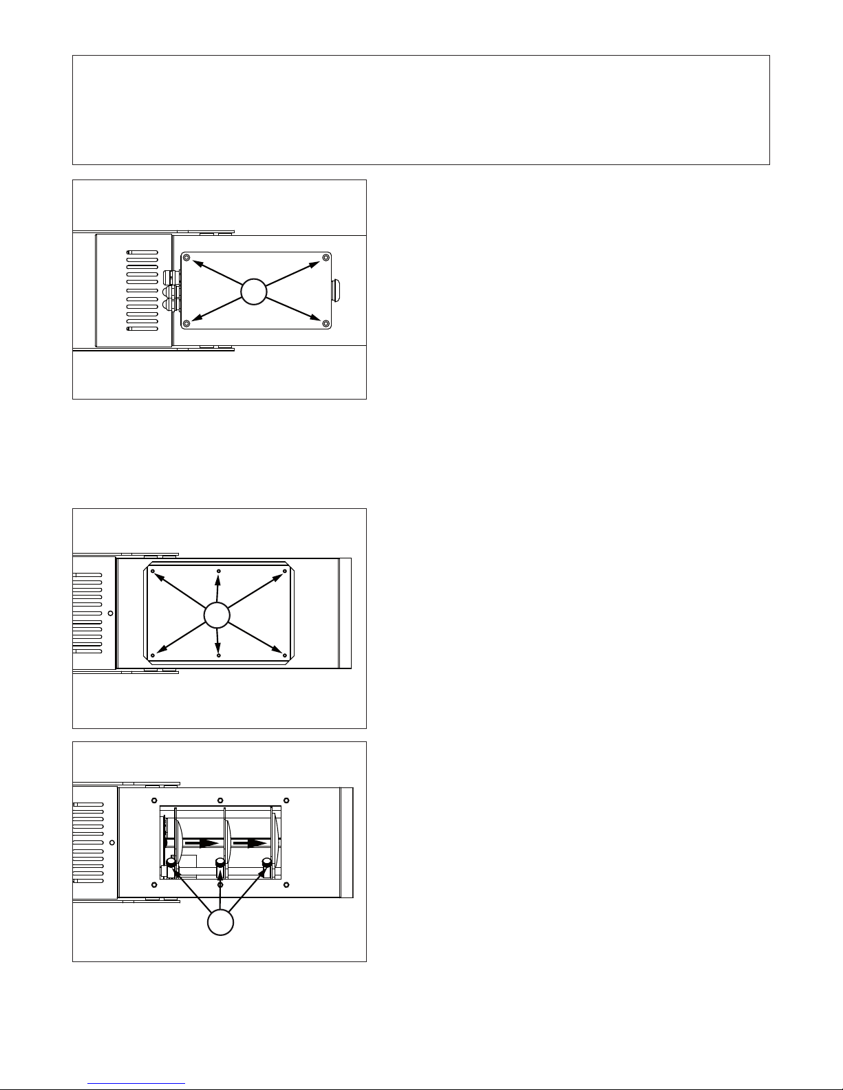
4.1 Fixing
The unit can be used both rested on floor and fixed onto a structure. The unit can operate in any position.
Use the holes “4” Ø10.5 (0.4”) in the bracket to fix the unit.
4.2 Adjusting light beam direction
A. Untighten the lateral screw “5”.
B. Rotate the bodies of the unit towards desired direction and
tighten the screw “5”.
4.0 Installation
Ø
8
0
m
m
3
.
2
”
Ø1
0
.5
m
m
0
.4
”
4
5
English 23
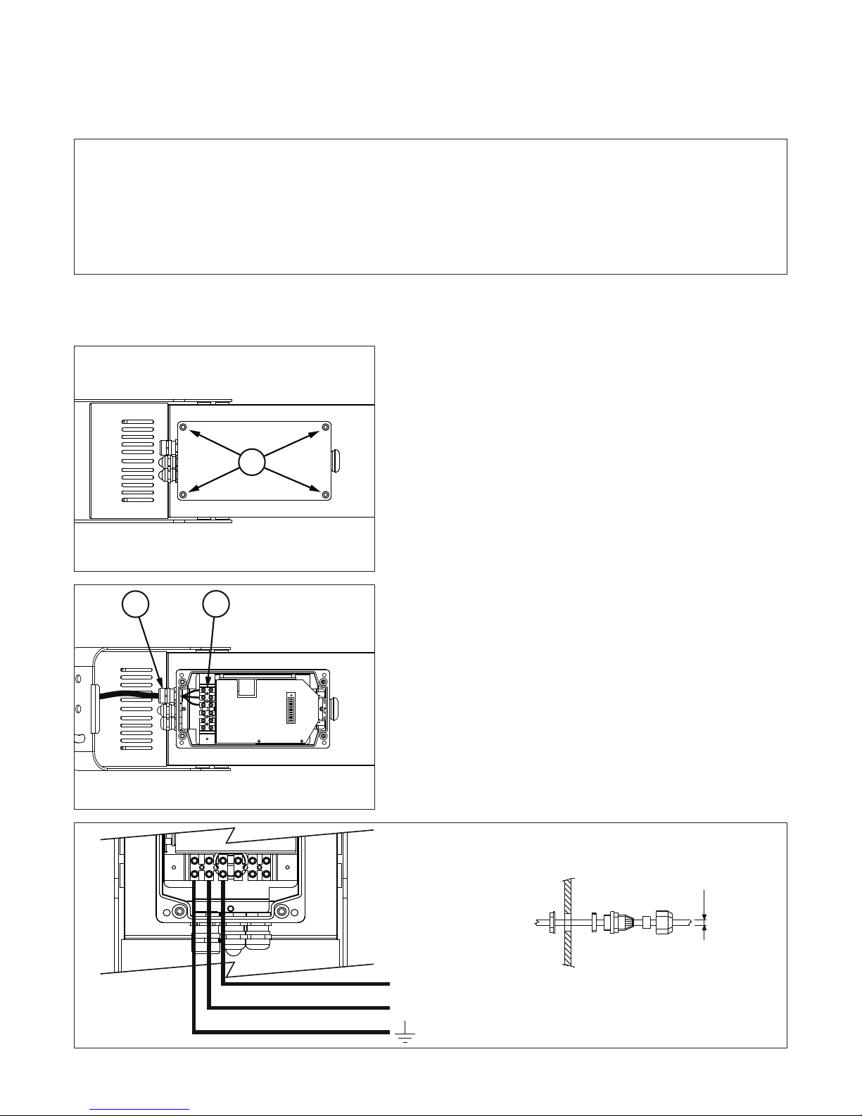
4.3 Connection to mains power
The unit can operate with voltage from 100 to 240Vac and with frequency of 50 and 60Hz.
It is not necessary to effect any setup procedures. The fixture will automatically adjust its operation to suit any fre-
quency or voltage within this range.
The unit is fitted with internal pins for the connection of the of the main cable, as shown in the following
pictures.
A. Untighten the screw “6” and remove the box cover.
B. Let the signal cables pass through the cable glands “7”
located onto the unit body and connect the main cables to
the pin “8”.
The connection of the cable to the unit must be performed respecting the label next to the terminal box.
Size and connection scheme of the main cable are shown in
the following picture.
Warning!
• Before connecting the unit, verify that power supplies features are compatible with the unit features.
• The unit must never be installed if not grounded electrically.
• It is suggested to use a magnetothermic switch along the power supply line, as prescribed by in force rules.
• The unit must not be powered up through a dimmer power device.
• Wiring and connection actions are to be performed by a qualified staff.
6
7
8
ø4.5 MIN
ø10 MAX
3x1.5mm
²
minimum cable
section
Ground
Neutral
Phase
Main cable size
L
N

24 English
C. Close the unit again by tighten the screw “6” previously re-
moved.
4.4 Connection to DMX signal
The DMX signal is to be connected by using a shielded cable designed for devices RS-485.
The unit is fitted with internal pins for the connection of the of the DMX signal cable, as shown in the following
pictures.
A. Untighten the screw “6” and remove the box cover.
B. Let the signal cables pass through the cable glands “9”
located onto the unit body and connect the DMX signal
cables to the pin “10”.
The connection of the cable to the unit must be performed respecting the label next to the terminal box, while from the end
of the DMX controller the connection must respect the following table:
pin 1 = GND
pin 2 = data pin 3 = data +
Size and connection scheme of the DMX cable are shown in
the following picture.
6
6
10
9
Pin 1: GND
Pin 2: DATA-
Pin 3: DATA+
ø4 MIN
ø8 MAX
DMX cable size
English 25
C. Close the unit again by tighten the screw “6” previously re-
moved.
4.5 Gobo installation
The gobo size is Ø53.3 mm with image Ø40 mm.
The size is compatible with standard “D size”.
A. Untighten the screw “11” and remove the lower cover.
B. Untighten the knob “12” and move sideways the lenses.
Warning!
All data wires must be isolated one from another, from the shield and from the metal housing of the connectors.
Pin number 1 of the housing is not to be connected to the electric ground of the unit.
Insert a 120 Ω resistor connected to Data+ and Data- in the last unit.
6
11
12

26 English
C. Insert the gobo in the gear “13”.
D. Insert the rubber gobo holder “14”.
E. Block the gobo by using the spring “15”.
F. Close the unit again by tighten the screw “11” previously re-
moved.
13
14
15
11

English 27
4.6 Focus and zoom
A. Untighten the screw “11” and remove the lower cover.
B. Move the lenses on order to adjust the beam angle and then
tighten the knob “12”.
C. Close the unit again by tighten the screw “11” previously
removed.
Goboled 80 D produces an manually adjustable beam between 19° and 35°.
111211

28 English
5.1 Setting operating mode
By the dip-switch set it is possible to select one of the following operating modes:
• using DMX512 signal control mode
Each fixture is controlled from DMX512 signal control.
• MASTER-SLAVE or AUTOMATIC mode
The projector operates independently, without DMX512 signal control.
5.2 Setting DMX address
To access to the dip-switch panel it is necessary untighten the
screw “6” and remove the box cover.
One led is next to the dip-switch panel to notify the status of the
unit.
In the presence of DMX signal, the red led “16” will be steady on,
when the projector functions as master, the red led will flash,
while in the absence of the signal the led will remain off.
When power is connected, the green LED "17" will always be on.
The number of DMX channels used by the unit to operate will depend from the selected operating mode.
In case of more units operating in mode CH MODE = 1, the first unit will be set with address 001, the second unit
with address 004, the third unit with address 007, etc.
In case of more units operating in CH MODE = 2 mode, the first unit will be set with address 001, the second unit
with address 005, the third unit with address 009, etc.
The number of the DMX address is to be calculated by summing the values corresponding to the activated dipswitches, which are written in the upper side of the dip-switch set (1, 2, 4, 8, 16, etc.).
5.0 Use of the unit
6
16
17
DIP 10 DIP 11 DMX MODE DMX CHANNELS USED BY THE UNIT
OFF OFF 1 3
OFF ON 2 4
ON OFF 3 1
ON ON 4 2

English 29
5.3 DMX functions
5.3.1 DMX functions in CH mode = 1
Example
Unit with address 005
(dip-switch n°1 and 3= ON)
and CH MODE = OFF
12345678910 11 12
1
248
163264
128
256
Master
CH mode
CH mode
Example
Unit with address 007
(dip-switch n°1, 2 and 3 = ON)
and CH MODE = ON
12345678910 11 12
1
248
163264
128
256
CH mode
Master
CH mode
Attention!
In absence of DMX signal the led will remain OFF.•
If required by DMX, at the end of the reset operation, the LED will light up.•
When channel 2 is in the active range (8-248), it takes precedence over channel 1.•
Channel Function Value Description
1
Gobo
rotation
0-15 No rotation
16-150 Proportional control 0-100% of the clockwise rotation
151-160 No rotation
161-255 Proportional control 0-100% of the counterclockwise rotation
2 Indexing
0-7 No effect
8-248 360° gobo indexing
249-255 No effect
3
Blackout
Dimmer
Strobo
0-15 Luminous output intensity 100%
16-150 Proportional control of the luminous output intensity 100-0%
151-160 Luminous output intensity 100%
161-255 Proportional control of the Strobe effect

30 English
5.3.2 DMX functions in CH mode = 2
5.3.3 DMX functions in CH mode = 3
5.3.4 DMX functions in CH mode = 4
Channel Function Value Description
1
Gobo
Rotation
0-15 No rotation
16-150 Proportional control 0-100% of the clockwise rotation
151-160 No rotation
161-255 Proportional control 0-100% of the counterclockwise rotation
2 Indexing
0-7 No effect
8-248 360° gobo indexing
249-255 No effect
3 Dimmer
0-5 Luminous output intensity 0%
6-250 Proportional control of the luminous output intensity 0-100%
251-255 Luminous output intensity 100%
4 Strobo
0-5 Strobe frequency 0%
6-250 Proportional control of the strobe frequency 0-100%
251-255 Strobe frequency 100%
Channel Function Value Description
1
Blackout
Dimmer
Strobo
0-15 Luminous output intensity 100%
16-150 Proportional control of the luminous output intensity 100-0%
151-160 Luminous output intensity 100%
161-255 Proportional control of the Strobe effect
Channel Function Value Description
1 Dimmer
0-5 Luminous output intensity 0%
6-250 Proportional control of the luminous output intensity 0-100%
251-255 Luminous output intensity 100%
2 Strobo
0-5 Strobe frequency 0%
6-250 Proportional control of the strobe frequency 0-100%
251-255 Strobe frequency 100%
English 31
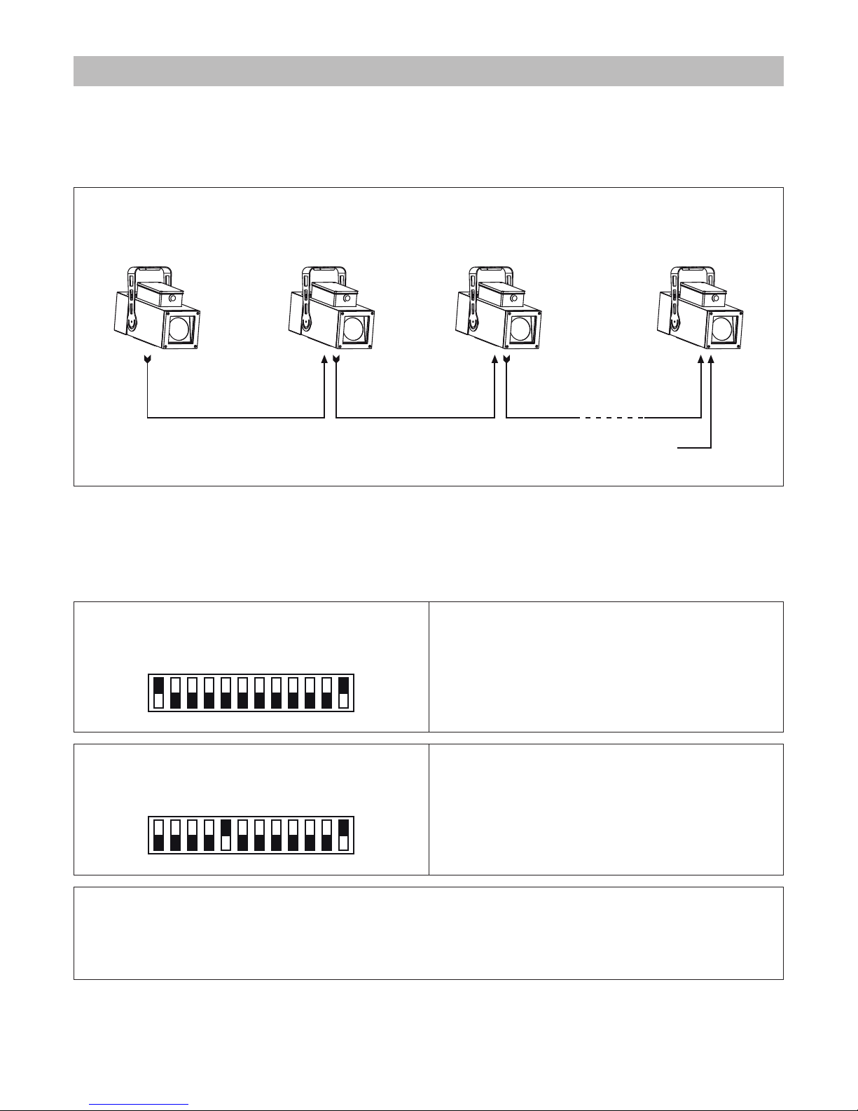
Goboled 80 can operate without DMX signal (in AUTOMATIC mode) and can be set so that a single MASTER unit
will command a series of SLAVE units. This function is particularly useful when more units are desired to execute the
same programme in synchrony.
The following picture shows an example of a Master-Slave layout.
6.1 MASTER configuration
To execute a preset programme set the dip-switch Master to ON and choose the type of programme to be
executed.
The following pictures show some examples of MASTER units configuration.
The following table shows the output effect according to the programme.
MASTER SLAVE 1 SLAVE N
INOUTINOUT
SLAVE 2
INOUT
Terminal resistor
120 Ohm
6.0 Master-Slave and Automatic function
Unit set as Master (Master = ON)
program 1° SPEED DX (right) running
(dip-switch 1 = ON)
12345678910 11 12
1° SPEED DX
2° SPEED DX
3° SPEED DX
4° SPEED DX
1° SPEED SX
2° SPEED SX
3° SPEED SX
4° SPEED SX
RANDOM
Ch. Mode
Ch. Mode
MASTER
Unit set as Master (Master = ON)
program 1° SPEED SX (left) running
(dip-switch 5 = ON)
12345678910 11 12
1° SPEED DX
2° SPEED DX
3° SPEED DX
4° SPEED DX
1° SPEED SX
2° SPEED SX
3° SPEED SX
4° SPEED SX
RANDOM
Ch. Mode
Ch. Mode
MASTER
Attention!
If MASTER-SLAVE mode is being used, no other DMX control device must be present along the line!!

32 English
6.2 SLAVE configuration
To set up the unit as SLAVE adjust all the dip-switches to OFF.
If the unit is properly set up as SLAVE and the signal is present, the red led next to the dip-switch panel will constantly remain on.
The following picture shows an example of configuration of SLAVE units.
6.3 AUTOMATIC configuration
To set up the unit as AUTOMATIC the same instructions for the set up as MASTER must be followed (see paragraph
8.1 MASTER configuration). Adjust the dip-switch Master to ON and choose the programme to be executed.
Dip-switch Effect
1 Clockwise rotation speed 1
2 Clockwise rotation speed 2
3 Clockwise rotation speed 3
4 Clockwise rotation speed 4
5 Counterclockwise rotation speed 1
6 Counterclockwise rotation speed 2
7 Counterclockwise rotation speed 3
8 Counterclockwise rotation speed 4
9 Random rotation
Warning!
Set the dip-switches 1-9 to OFF to stop the rotating movement.
Slave unit (All switch = OFF)
12345678910 11 12
1
248
163264
128
256
Ch. Mode
DMX mode
Ch. Mode

English 33
An internal temperature sensor prevents the unit from overheating. The temperature sensor will limit the current
to leds, protecting their integrity, if the ambient temperature exceeds the one allowed.
To ensure maximum functionality and light output it is recommended to follow these instructions:
8.1 Cleaning the unit
8.1.1 Fixture body
The unit must be cleaned regularly. Cleaning regularity will depend especially on the environment where the unit
will operate: deposits of dust, smokes or other wastes will reduce the light output performances.
• Clean regularly the glass of the unit.
• Be careful when cleaning the components. Operate in a clean, properly illuminated environment.
• Do not use solvents which could damage painted surfaces.
• Remove left particles by a cotton towel dampened with a glass-cleaning liquid or distilled water.
• Remove smoke and other wastes by a cotton towel dampened with isopropyl alcohol.
• Dry out by a clean, soft, non-scratching towel or by compressed air.
8.1.2 Fans and air passages
The fans and air passages must be cleaned approximately every 6 weeks; the period for this periodic cleaning will
depend, of course, upon the conditions in which the projector is operating. Suitable instruments for performing this
type of maintenance are a brush and a common vacuum cleaner or an air compressor.
8.2 Regular checks
• Check electrical connections, especially the ground wiring and the power supply cable.
• Check that the unit is not damaged mechanically. Replace those components which have got deteriorated.
All components of the unit are available as spare parts at Griven dealers.
Exploded views, wiring diagrams, electronic layouts and advertising brochures are available on request.
To make the job of assistance centres easier, specify serial number and model of the unit which spare parts are
requested for.
7.0 Thermal protection
Attention!
Goboled 80 D features a smart ventilation system.
The fan will turn on only when necessary.
8.0 Maintenance
Attention!
Always remove mains power prior to opening up the fixture.
9.0 Spare parts

10.0 Troubleshooting
Inconvenience Possibile Cause Action
The fixture will not turn
on.
Unit not powered up.
Check that the power supply cable is connected and the
unit is powered.
Out of order PCB Check the PCB functions.
The unit does not
respond properly
to the DMX control.
Incorrect DMX cable
connection.
Check connections and wires. Rectify inefficient connections. Repair or replace damaged wires.
Unfinished data connection.
Insert a 120Ω resistor connected to pins Data+ and Dataof the last unit of the connection.
Incorrect address
assignment to the units.
Check the addresses of the units and the protocol settings.
One of the unit is faulty and
it is affecting the data
transmission along the
connection.
Short-circuit units singularly, one by one,
since regular working is restored.
The unit is set to Master
or Automatic, but is not
running any programs.
In addition to setting the
Master dip-switch to ON, it is
necessary to also select a
program number.
Select a program number.
There more than a unit is set
to Master.
Check that amongst the interconnected fixtures, only one
has been set to Master.
Conflict in signals. Ensure that there is no incoming DMX signal.
34 English

The European Directive 2002/96/EC on Waste Electrical and Electronic Equipment (WEEE), requires that old
lighting fixtures must not be disposed of the normal unsorted municipal waste stream. Old appliances must be
collected separately in order to optimise the recovery and recycling of the materials they contain and reduce
the impact on human health and the environment.
The crossed out “wheeled bin” symbol on the product reminds you of your obligation, that when
you dispose of the appliance it the must be separately collected.
Consumer should contact their local authority or retailer for information conceming the correct disposal of their old appliance.
Mechanical features
Height . . . . . . . . . . . . . . . . . . . . . . . . . . . . . . . . . . . . . . . . . . . . . . . . . . . . . . . . . . . . . . . . . . . . . . . . . . . . . .280.5mm (11”)
Width . . . . . . . . . . . . . . . . . . . . . . . . . . . . . . . . . . . . . . . . . . . . . . . . . . . . . . . . . . . . . . . . . . . . . . . . . . . . . . . .164mm (6.5”)
Depth . . . . . . . . . . . . . . . . . . . . . . . . . . . . . . . . . . . . . . . . . . . . . . . . . . . . . . . . . . . . . . . . . . . . . . . . . . . . .425.3mm (16.7”)
Weight . . . . . . . . . . . . . . . . . . . . . . . . . . . . . . . . . . . . . . . . . . . . . . . . . . . . . . . . . . . . . . . . . . . . . . . . . . . . . .8.7Kg (19.2Lbs)
Thermal features
Maximum ambient temperature . . . . . . . . . . . . . . . . . . . . . . . . . . . . . . . . . . . . . . . . . . . . . . . . . . . . . . . . . .40°C (104°F)
Maximum surface temperature . . . . . . . . . . . . . . . . . . . . . . . . . . . . . . . . . . . . . . . . . . . . . . . . . . . . . . . . <60°C ( <140°F)
Electrical features
Voltage . . . . . . . . . . . . . . . . . . . . . . . . . . . . . . . . . . . . . . . . . . . . . . . . . . . . . . . . . . . . . . . . . . . . . . . .100-240 Vac 50/60Hz
Nominal current . . . . . . . . . . . . . . . . . . . . . . . . . . . . . . . . . . . . . . . . . . . . . . . . . . . . . . . . . . . . . . . . . . . . . . . . 0.5A @ 230V
Maximum power . . . . . . . . . . . . . . . . . . . . . . . . . . . . . . . . . . . . . . . . . . . . . . . . . . . . . . . . . . . . . . . . . . . . . . . . . . . . . 100W
Power factor . . . . . . . . . . . . . . . . . . . . . . . . . . . . . . . . . . . . . . . . . . . . . . . . . . . . . . . . . . . . . . . . . . . . . . . . . . .cos φ = 0.87
Thermal protection . . . . . . . . . . . . . . . . . . . . . . . . . . . . . . . . . . . . . . . . . . . . . . . . . . . . . . . . . . . . . . . . . . . . . . . Electronic
Light output source
Type of light output source . . . . . . . . . . . . . . . . . . . . . . . . . . . . . . . . . . . . . . . . . . . . . . . . . . . . . . . . . . . . . . . 1 Led x 80W
Optics
Optical system . . . . . . . . . . . . . . . . . . . . . . . . . . . . . . . . . . . . . . . . . . . . . . . . . . . . . . . . . . . . . . . . . . . . . . . . . . . . . Lenses
Available optics . . . . . . . . . . . . . . . . . . . . . . . . . . . . . . . . . . . . . . . . . . . . . . . . . . . . . . . . . . . . . . . . . . . . . . . . . . . 19° - 35°
Control
Protocol . . . . . . . . . . . . . . . . . . . . . . . . . . . . . . . . . . . . . . . . . . . . . . . . . . . . . . . . . . . . . . . . . . . . . . . . . . . . . USITT DMX-512
Control channel . . . . . . . . . . . . . . . . . . . . . . . . . . . . . . . . . . . . . . . . . . . . . . . . . . . . . . . . . . . . . . . . . . . . . . . . . . . 1, 2, 3, 4
Construction
Unit body . . . . . . . . . . . . . . . . . . . . . . . . . . . . . . . . . . . . . . . . . . . . . . . . . . . . . . . . . . . . . . . . . . . . . . . . . . . Iron/Aluminium
Treatment . . . . . . . . . . . . . . . . . . . . . . . . . . . . . . . . . . . . . . . . . . . . . . . . . . . . . . . . . . . . . . . Scratch resistant black paint
Weather protection rate
Fixture body . . . . . . . . . . . . . . . . . . . . . . . . . . . . . . . . . . . . . . . . . . . . . . . . . . . . . . . . . . . . . . . . . . . . . . . . . . . . . . . . . . IP65
Cooling system . . . . . . . . . . . . . . . . . . . . . . . . . . . . . . . . . . . . . . . . . . . . . . . . . . . . . . . . . . . . . . . . . . . . . . . . . . . . . . . . IP55
11.0 Disposal
12.0 Technical specifications
English 35

Via Bulgaria, 16 - 46042 CASTEL GOFFREDO (MN) - Italy
Telefono 0376/779483 - Fax 0376/779682 - 0376/779552
http://www.griven.com/ e-mail griven@griven.com
http://www.griven.it/ e-mail griven@griven.it
User’s manual rel. 1.40
 Loading...