

POWERSHINE MK2 D
Manuale di istruzioni
Instructions manual

INDICE
1.0 Introduzione ..........................................................................................................................................................................................4
1.1 Informazioni di sicurezza......................................................................................................................................................................4
1.1.1 Protezione da scariche elettriche...................................................................................................................................................4
1.1.2 Installazione .......................................................................................................................................................................................4
1.1.3 Protezione dagli incendi ..................................................................................................................................................................4
1.1.4 Protezione da solidi e liquidi.............................................................................................................................................................4
1.2 Condizioni di garanzia.........................................................................................................................................................................4
1.3 Normative .............................................................................................................................................................................................4
2.0 Dimensioni.............................................................................................................................................................................................5
3.0 Imballo e trasporto...............................................................................................................................................................................5
3.1 Imballo...................................................................................................................................................................................................5
3.2 Trasporto................................................................................................................................................................................................5
4.0 Installazione ..........................................................................................................................................................................................6
4.1 Fissaggio................................................................................................................................................................................................6
4.2 Orientamento del fascio di luce ........................................................................................................................................................6
4.3 Collegamento della tensione di alimentazione...............................................................................................................................7
4.4 Collegamento del segnale DMX .......................................................................................................................................................7
5.0 Utilizzo del proiettore............................................................................................................................................................................8
5.1 Impostazione modo di funzionamento .............................................................................................................................................8
5.2 Pannello di controllo del proiettore ...................................................................................................................................................8
5.2.1 Funzione dei pulsanti ........................................................................................................................................................................8
6.0 Funzionamento in modalità DMX.......................................................................................................................................................9
6.1 Configurazione del numero dei canali DMX ....................................................................................................................................9
6.2 Impostazione indirizzo DMX.................................................................................................................................................................9
6.3 Funzioni DMX RGBW.............................................................................................................................................................................9
6.3.1 Funzioni DMX con modalità 4 canali ..............................................................................................................................................9
6.3.2 Funzioni DMX con modalità 5 canali ..............................................................................................................................................9
6.3.3 Funzioni DMX con modalità 6 canali ............................................................................................................................................10
6.3.4 Funzioni DMX con modalità 8 canali ............................................................................................................................................10
6.3.5 Funzioni DMX con modalità 10 canali ..........................................................................................................................................10
6.3.6 Funzioni DMX con modalità 12 canali ..........................................................................................................................................11
6.4 Funzioni DMX bianco dinamico .......................................................................................................................................................12
6.4.1 Funzioni DMX con modalità 2 canali ............................................................................................................................................12
6.4.2 Funzioni DMX con modalità 3 canali ............................................................................................................................................12
6.4.3 Funzioni DMX con modalità 4 canali ............................................................................................................................................13
6.4.4 Funzioni DMX con modalità 6 canali ............................................................................................................................................14
6.5 Funzioni DMX monocromatico .........................................................................................................................................................14
6.5.1 Funzioni DMX con modalità 1 canale ..........................................................................................................................................14
6.5.2 Funzioni DMX con modalità 2 canali ............................................................................................................................................14
7.0 MASTER-SLAVE e AUTOMATICO (solo RGBW e DW) .......................................................................................................................15
7.1 Configurazione AUTOMATICO..........................................................................................................................................................15
7.2 Configurazione MASTER ....................................................................................................................................................................16
7.3 Configurazione SLAVE .......................................................................................................................................................................16
8.0 Funzionamento in modalità COLORI FISSI (solo RGBW e DW) ......................................................................................................16
8.1 Configurazione MASTER RGBW.........................................................................................................................................................16
8.2 Configurazione MASTER DW .............................................................................................................................................................16
8.3 Configurazione SLAVE .......................................................................................................................................................................16
9.0 Dimmer (solo monocromatico)........................................................................................................................................................17
10.0 Temperatura dei led........................................................................................................................................................................17
11.0 Temperatura dei driver dei led.......................................................................................................................................................17
12.0 Temperatura del corpo (solo versioni Polar).................................................................................................................................17
13.0 Potenza del riscaldatore (solo versioni Polar) ...............................................................................................................................17
14.0 Impostazioni di default ....................................................................................................................................................................17
14.1 Pulizia del proiettore ........................................................................................................................................................................18
14.2 Controlli periodici .............................................................................................................................................................................19
14.3 Coppie di serraggio.........................................................................................................................................................................19
15.0 Funzioni RDM.....................................................................................................................................................................................18
16.0 Protezione termica...........................................................................................................................................................................18
17.0 Vetro no-frost ....................................................................................................................................................................................18
18.0 Manutenzione...................................................................................................................................................................................18
19.0 Parti di ricambio ...............................................................................................................................................................................19
20.0 Smaltimento dell’apparecchiatura...............................................................................................................................................19
21.0 Ricerca dei guasti ............................................................................................................................................................................21
22.0 Specifiche tecniche.........................................................................................................................................................................21

INDEX
1.0 Introduction ........................................................................................................................................................................................21
1.1 Safety information..............................................................................................................................................................................21
1.1.1 Protecting against electric shock .................................................................................................................................................21
1.1.2 Installation ........................................................................................................................................................................................21
1.1.3 Protection against burns and fire..................................................................................................................................................21
1.1.4 Weather protection ........................................................................................................................................................................21
1.2 Warranty conditions...........................................................................................................................................................................21
1.3 Compliance........................................................................................................................................................................................21
2.0 Size .......................................................................................................................................................................................................22
3.0 Packaging and transport ..................................................................................................................................................................22
3.1 Packaging...........................................................................................................................................................................................22
3.2 Transport..............................................................................................................................................................................................22
4.0 Installation ...........................................................................................................................................................................................23
4.1 Fixing ....................................................................................................................................................................................................23
4.2 Adjusting light beam direction .........................................................................................................................................................23
4.3 Connection to mains power.............................................................................................................................................................24
4.4 Connection to DMX signal ................................................................................................................................................................24
5.0 Use of the unit.....................................................................................................................................................................................25
5.1 Setting operating mode....................................................................................................................................................................25
5.2 Unit control panel...............................................................................................................................................................................25
5.2.1 Reading the display and using controls .......................................................................................................................................25
6.0 DMX function mode ..........................................................................................................................................................................26
6.1 Setting DMX channels........................................................................................................................................................................26
6.2 Setting DMX address..........................................................................................................................................................................26
6.3 DMX functions RGBW.........................................................................................................................................................................26
6.3.1 DMX functions with DMX MODE = 4 channels .............................................................................................................................26
6.3.2 DMX functions with DMX MODE = 5 channels .............................................................................................................................26
6.3.3 DMX functions with DMX MODE = 6 channels .............................................................................................................................27
6.3.4 DMX functions with DMX MODE = 8 channels .............................................................................................................................27
6.3.5 DMX functions with DMX MODE = 10 channels ...........................................................................................................................27
6.3.6 DMX functions with DMX MODE = 12 channels ...........................................................................................................................28
6.4 DMX functions dynamic white..........................................................................................................................................................29
6.4.1 DMX functions with DMX MODE = 2 channels .............................................................................................................................29
6.4.2 DMX functions with DMX MODE = 3 channels .............................................................................................................................29
6.4.3 DMX functions with DMX MODE = 4 channels .............................................................................................................................30
6.4.4 DMX functions with DMX MODE = 6 channels .............................................................................................................................31
6.5 DMX functions monochrome............................................................................................................................................................31
6.5.1 DMX functions with DMX MODE = 1 channel ..............................................................................................................................31
6.5.2 DMX functions with DMX MODE = 2 channels .............................................................................................................................31
7.0 Master-Slave and Automatic function (only RGBW and DW) ......................................................................................................32
7.1 AUTOMATIC configuration ................................................................................................................................................................32
7.2 MASTER configuration........................................................................................................................................................................33
7.3 SLAVE configuration...........................................................................................................................................................................33
8.0 FIXED COLOURS mode (only RGBW and DW) ................................................................................................................................33
8.1 RGBW MASTER configuration............................................................................................................................................................33
8.2 Dynamic white MASTER configuration ............................................................................................................................................33
8.3 SLAVE configuration...........................................................................................................................................................................33
9.0 Dimmer ( Monochromatic ) ..............................................................................................................................................................34
10.0 Led temperature ..............................................................................................................................................................................34
11.0 Temperature of led drivers .............................................................................................................................................................34
12.0 Body Temperature ( only Polar versions) .......................................................................................................................................34
13.0 Heating Power ( only Polar versions ).............................................................................................................................................34
14.0 Default setting ..................................................................................................................................................................................34
14.1 Cleaning the unit .............................................................................................................................................................................36
14.2 Regular checks.................................................................................................................................................................................36
14.3 Tightening torque.............................................................................................................................................................................36
15.0 RDM functions...................................................................................................................................................................................35
16.0 Thermal protection...........................................................................................................................................................................35
17.0 No frost glass .....................................................................................................................................................................................35
18.0 Maintenance....................................................................................................................................................................................36
19.0 Spare parts........................................................................................................................................................................................36
20.0 Disposal .............................................................................................................................................................................................36
21.0 Troubleshooting ................................................................................................................................................................................37
22.0 Technical specifications..................................................................................................................................................................37
4 Italiano
1.1 Informazioni di sicurezza
1.1.1 Protezione da scariche elettriche
• Togliere l’alimentazione prima di effettuare qualsiasi operazione all’interno dell’apparecchiatura.
• Non utilizzate l’apparecchiatura in assenza di una connessione di terra.
• Prima di connettere l’apparecchio alla rete elettrica, verificate la compatibilità di tensione e frequenza.
• Non maneggiate il prodotto con mani bagnate o in presenza di acqua.
• Controllate periodicamente che il cavo di alimentazione non sia schiacciato o danneggiato.
• Rivolgersi ad un tecnico qualificato per qualsiasi operazione di manutenzione ordinaria non descritta nel presente manuale.
1.1.2 Installazione
• Fissate il proiettore con viti, ganci o altri supporti in grado di sostenerne il peso.
• Le operazioni di installazione dell’apparecchiatura devono essere eseguite da personale competente e qualificato.
1.1.3 Protezione dagli incendi
• Idoneo ad essere installato su superfici normalmente infiammabili.
• Non installate l’apparecchio in locali in cui la temperatura ambiente supera i 50° (122°F).
1.1.4 Protezione da solidi e liquidi
Il proiettore rientra nella classificazione di apparecchio con grado di protezione IP66
1.2 Condizioni di garanzia
• Ogni articolo prodotto dalla ditta italiana GRIVEN Srl è stato assemblato e costruito in conformità alle vigenti
norme e normative CE.
• Ogni singolo prodotto e componente sono stati testati prima dell’assemblaggio finale ed ogni prodotto è sottoposto ad un controllo di qualità interno prima di essere spedito.
• GRIVEN Srl garantisce la buona qualità e realizzazione dei propri prodotti e si impegna a riparare o sostituire a
propria discrezione, nel più breve tempo possibile, qualsiasi parte che – durante il periodo di garanzia – mostri
difetti di costruzione, assemblaggio o materiale.
• La garanzia è valida per la durata di 12 (dodici) mesi dalla data di consegna del prodotto.
• GRIVEN Srl non risponde dei danni riportati dal prodotto durante il trasporto oppure derivanti da un utilizzo improprio o da un’inappropriata manutenzione dello stesso.
• Sono escluse dalla presente garanzia tutte le parti considerate di consumo o soggette a normale logorio.
• Il cliente dovrà restituire le parti difettose alla GRIVEN Srl a suo carico e rischio.
• Le parti riparate o sostituire verranno spedite dalla GRIVEN ex-factory.
• Per ogni controversia sarà competente il foro di Mantova (Italia) in conformità alla relativa giurisdizione italiana.
1.3 Normative
• L’apparecchio soddisfa i requisiti della normativa EN60598-1 EN60598-2-17.
• L’apparecchio soddisfa i requisiti della direttiva 2002/95/CE (RoHS).
1.0 Introduzione
Attenzione!
Questo prodotto è adatto solo ad un uso professionale, non ad un uso domestico.
Italiano 5
3.1 Imballo
Controllate attentamente il contenuto del cartone e, in caso di danni al prodotto, contattate il Vs. trasportatore.
Nell’imballaggio del presente proiettore sono contenuti i seguenti prodotti:
n° 1 proiettore POWERSHINE MK2 D
n° 1 manuale di istruzioni
n° 2 kit di connessione
3.2 Trasporto
La scatola di cartone non è progettata per essere usata più di una volta perciò si raccomanda vivamente l’uso
di uno dei nostri flight case per trasportare l’apparecchiatura.
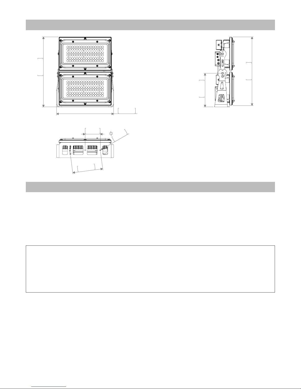
2.0 Dimensioni
696mm
27,41in
567mm
22,32in
334mm
13,16in
682mm
26,85in
1
2
.5m
m
0,
5i
n
150mm
5,91in
300mm
1
1,
81i
n
3.0 Imballo e trasporto
Attenzione!
• La responsabilità di Griven S.r.l. cessa all’atto della consegna del materiale al vettore: reclami per eventuali
danni dovuti al trasporto dovranno essere indirizzati direttamente al corriere.
• Si accettano reclami entro e non oltre i 7 giorni dal ricevimento della merce.
• Eventuali resi di materiale dovranno essere autorizzati da Griven S.r.l. ed inviati completi della documentazione
fiscale necessaria.
6 Italiano
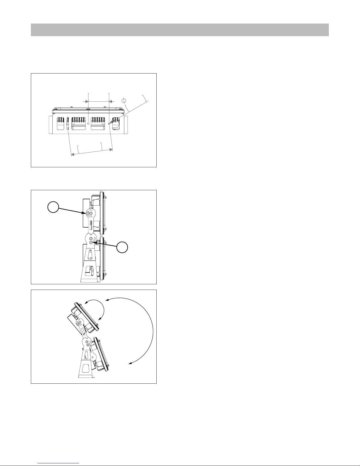
4.1 Fissaggio
Il proiettore può essere utilizzato sia appoggiato a terra che fissato ad una struttura e può funzionare in qualsiasi
posizione.
Utilizzate i fori Ø12.5 (1/2”) o Ø6.5 (0.25”) sulla forcella per fissare
l’apparecchiatura.
4.2 Orientamento del fascio di luce
A. Allentate le viti laterali “3”.
B. Ruotare il corpo nella direzione desiderata e serrate le viti.
4.0 Installazione
1
2
.
5
m
m
0
,
5
i
n
150mm
5,91in
3
0
0
mm
1
1
,
8
1
i
n
3
3
Italiano 7
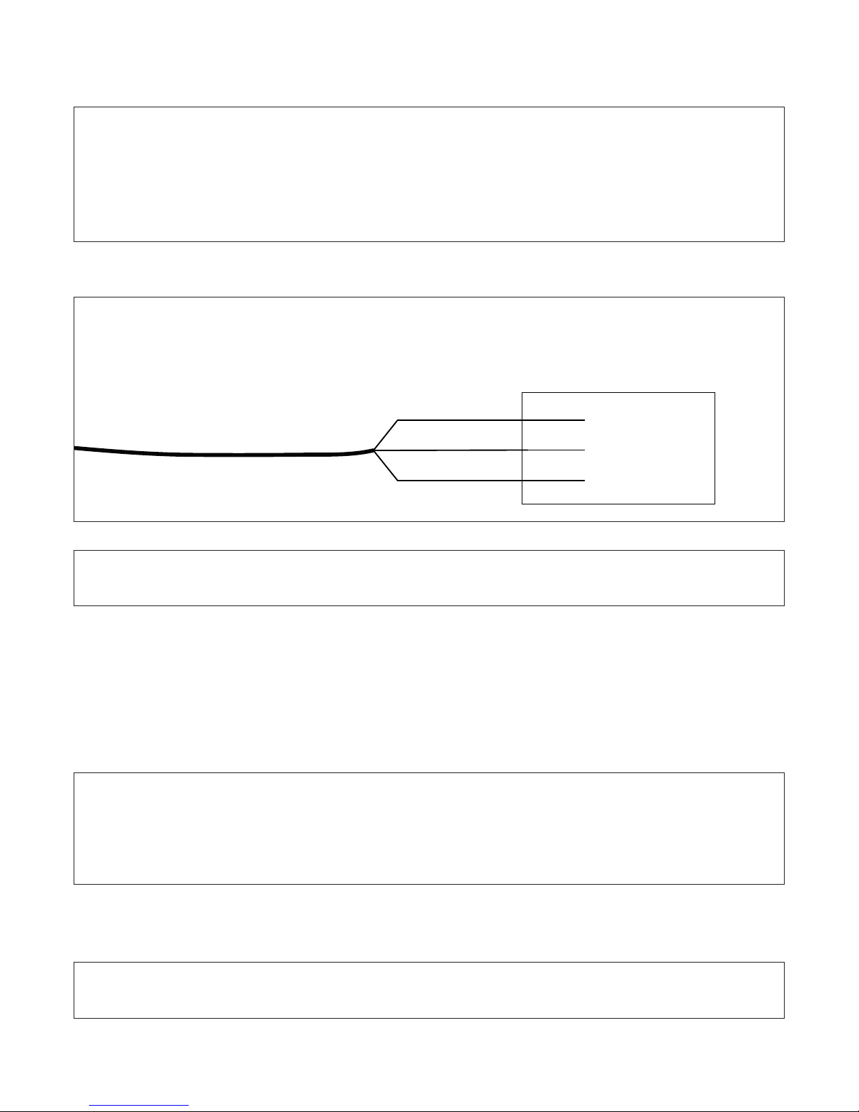
4.3 Collegamento della tensione di alimentazione
Il proiettore può funzionare con tensioni da 100-277Vac e con frequenze di 50 e 60Hz.
Collegate il cavo di alimentazione posteriore secondo lo schema riportato nella figura seguente.
4.4 Collegamento del segnale DMX
Il segnale DMX deve essere collegato utilizzando un cavo schermato progettato per congegni RS-485.
Il cavo di segnale deve essere collegato rispettando la seguente tabella:
GND = schermatura
DATA- = nero
DATA+ = rosso
Il proiettore è fornito di giunti e guaina termoretraibile che permettono di ottenere connessioni con grado IP67.
Per effettuare la connessione seguite le istruzioni riportate qui di seguito.
Attenzione!
• Prima di collegare l’apparecchio assicuratevi che la fornitura elettrica corrisponda a quelle ammesse.
• Non installate mai l’apparecchio senza la connessione di terra.
• E’ consigliato l’uso di un interruttore magnetotermico/differenziale sulla linea di alimentazione, come prescritto
dalle norme in vigore.
• Non alimentate il proiettore attraverso unità di potenza dimmer.
• Le operazioni di cablaggio e collegamento devono essere eseguite da personale qualificato.
Fase
Terra
Neutro
Marrone
Giallo Verde
Blu
Tensione di alimentazione
Attenzione!
Seguire le istruzioni fornite con il kit di connessione per effettuare i collegamenti.
Attenzione!
La schermatura ed i conduttori non devono fare alcun tipo di contatto tra loro.
Il GND del segnale DMX non deve essere collegato alla massa elettrica dell’apparecchio.
Nell’ultima apparecchiatura della linea DMX inserite una resistenza di terminazione
con resistenza da 120 Ω collegata tra DATA- e DATA+.
Attenzione!
Seguire le istruzioni fornite con il kit di connessione per effettuare i collegamenti.
8 Italiano
5.1 Impostazione modo di funzionamento
Mediante il pannello display è possibile selezionare uno dei seguenti modi di funzionamento:
• In modalità DMX
Il proiettore viene controllato tramite segnale DMX512.
(vedi capitolo Funzionamento DMX).
• In modalità MASTER-SLAVE o AUTOMATICA (AUT) (solo RGBW e DW)
Il proiettore funziona in modo indipendente, senza bisogno di centraline di controllo
(vedi capitolo 9.0 Funzionamento Master-Slave e Automatico).
• In modalità COLORI-FISSI (COL) (solo RGBW e DW)
Il proiettore funziona in modo indipendente senza bisogno di centraline di controllo e rimane
sempre su un colore impostato.
(vedi capitolo Funzionamento con colori fissi).
Il proiettore NORMALMENTE funziona in modalità DMX e all’accensione visualizza a display il numero di indirizzo
DMX (es. 012).
Se all’accensione il display visualizza “AUT” significa che il proiettore stà funzionando in modalità AUTOMATICA.
Disabilitare la funzione per tornare al funzionamneto DMX.
Se all’accensione il displayvisualizza “COL” significa che il proiettore stà funzionando in modalità COLORI FISSI.
Disabilitare la funzione per tornare al funzionamneto DMX.
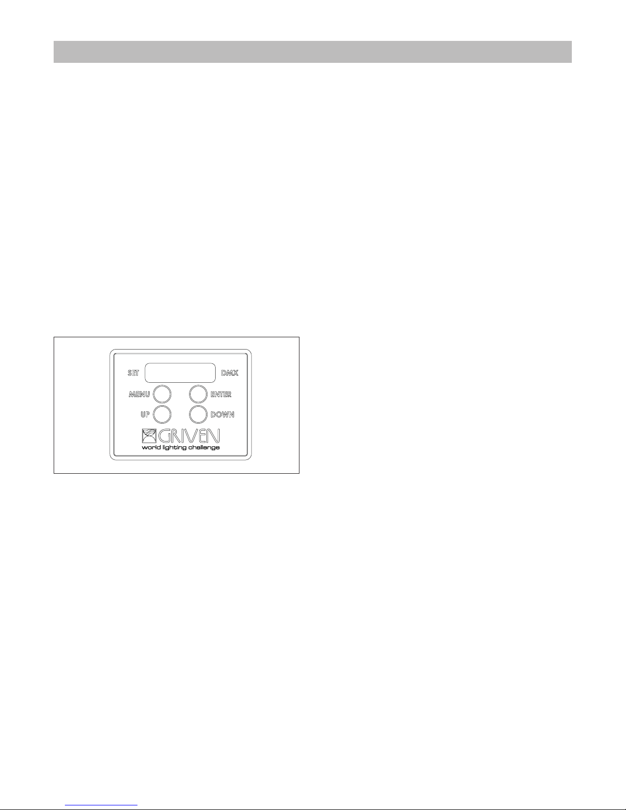
5.2 Pannello di controllo del proiettore
Il display del proiettore è programmato per spegnersi
automaticamente dopo 20 secondi di inattività.
Per attivarlo basta premere un qualsiasi tasto.
Il led DMX emette luce continua quando il proiettore riceve un segnale DMX, mentre lampeggia quando non
riceve alcun segnale.
Il led SET è attivo quando:
• viene cambiato l’indirizzo DMX
• viene modificato il menu
5.2.1 Funzione dei pulsanti
Pulsante MENU:
Premendo il pulsante “MENU” è possibile accedere al menù principale o uscire dalle funzioni, tornando al menù
principale.
Premendo il pulsante “MENU”, quando è visualizzato l’indirizzo DMX, si accede al menu principale.
Utilizzando i tasti “UP” e “DOWN”, il display mostra in sequenza le seguenti funzioni:
• Settaggio indirizzo DMX ADR
• Settaggio numero canali DMX CHN (solo RGBW e DW)
• Modalità AUTOMATICO AUT (solo RGBW e DW)
• Modalità COLORI FISSI COL (solo RGBW e DW)
• Dimmer in assenza di DMX DIM (solo monocromatico)
• Temperatura dei led LET
• Temperatura dei driver DRT
• Temperatura del corpo BOT (solo versioni Polar)
• Potenza riscaldatore HEP (solo versioni Polar)
• Impostazioni di default DEF
• Release software REL
Pulsanti UP e DOWN:
Premendo i pulsanti “UP” o “DOWN”, è possibile cambiare i valori della funzione mostrata sul display;
Pulsante ENTER:
Premere il pulsante “ENTER” (finché il display e il led SET lampeggiano) per attivare una funzione o memorizzare
5.0 Utilizzo del proiettore
Italiano 9
lil valore mostrato sul display.
6.1 Configurazione del numero dei canali DMX
Il numero di canali utilòizzato dipende dalla modalità selezionata:
Ogni proiettore RGBW può usare 4, 5, 6, 8, 10, 12 canali DMX.
Ogni proiettore bianco dinamico può usare 2, 3, 4, 6 canali DMX.
Ogni proiettore bianco dinamico può usare 1 o 2 canali DMX.
Per configurare il numero dei canali premete il tasto “MENU” fino a visualizzare “ADR”.
Premete il tasto “DOWN” fino a visualizzare “CHN” e premete “ENTER”.
Tramite i tasti “UP” e “DOWN” è possibile selezionare 1/../12 canali. Premete ENTER per confermare.
6.2 Impostazione indirizzo DMX
Per modificare l’indirizzo premete il pulsante “MENU”, selezionate “ADR” premendo il tasto “ENTER” per passare
al settaggio dell’indirizzo e tramite i pulsanti “UP” e “DOWN” selezionate il valore desiderato.
Premete “ENTER” per confermare.
6.3 Funzioni DMX RGBW
6.3.1 Funzioni DMX con modalità 4 canali
6.3.2 Funzioni DMX con modalità 5 canali
6.0 Funzionamento in modalità DMX
Attenzione!
In assenza del segnale DMX i led rimarranno SPENTI.
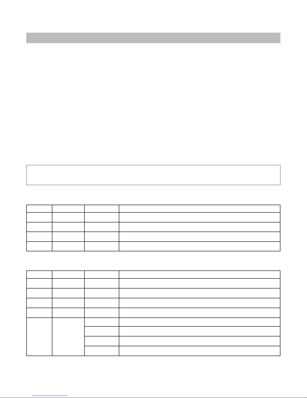
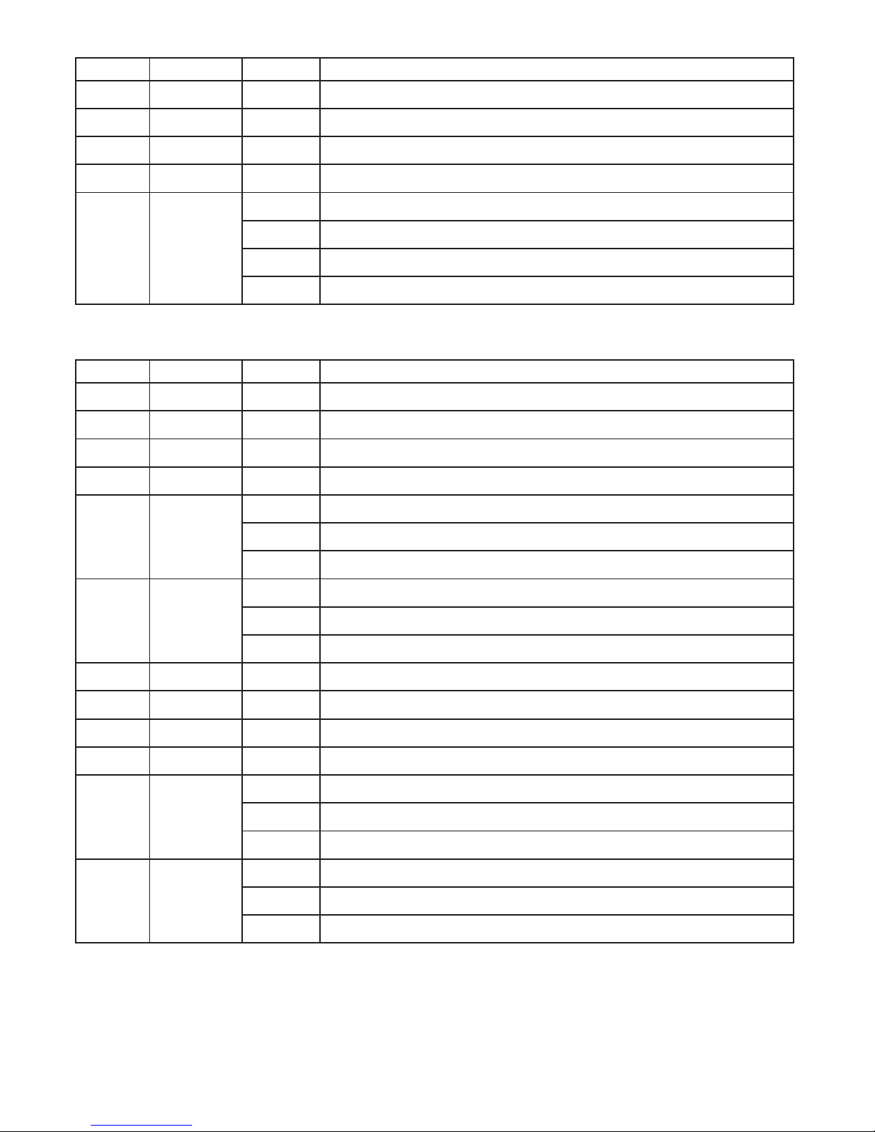
Canale Funzione Valore Descrizione
1 Rosso 0-255 Controllo proporzionale 0-100% del colore Rosso
2 Verde 0-255 Controllo proporzionale 0-100% del colore Verde
3 Blu 0-255 Controllo proporzionale 0-100% del colore Blu
4 Bianco 0-255 Controllo proporzionale 0-100% del colore Bianco
Canale Funzione Valore Descrizione
1 Rosso 0-255 Controllo proporzionale 0-100% del colore Rosso
2 Verde 0-255 Controllo proporzionale 0-100% del colore Verde
3 Blu 0-255 Controllo proporzionale 0-100% del colore Verde
4 Bianco 0-255 Controllo proporzionale 0-100% del colore Bianco
5
Dimmer
Strobo
0-15 Intensità luminosa 100%
16-150 Controllo proporzionale intensità luminosa 100-0%
151-160 Intensità luminosa 0%
161-255 Controllo proporzionale effetto strobo 0-100% (255=max)
10 Italiano
6.3.3 Funzioni DMX con modalità 6 canali
6.3.4 Funzioni DMX con modalità 8 canali
6.3.5 Funzioni DMX con modalità 10 canali
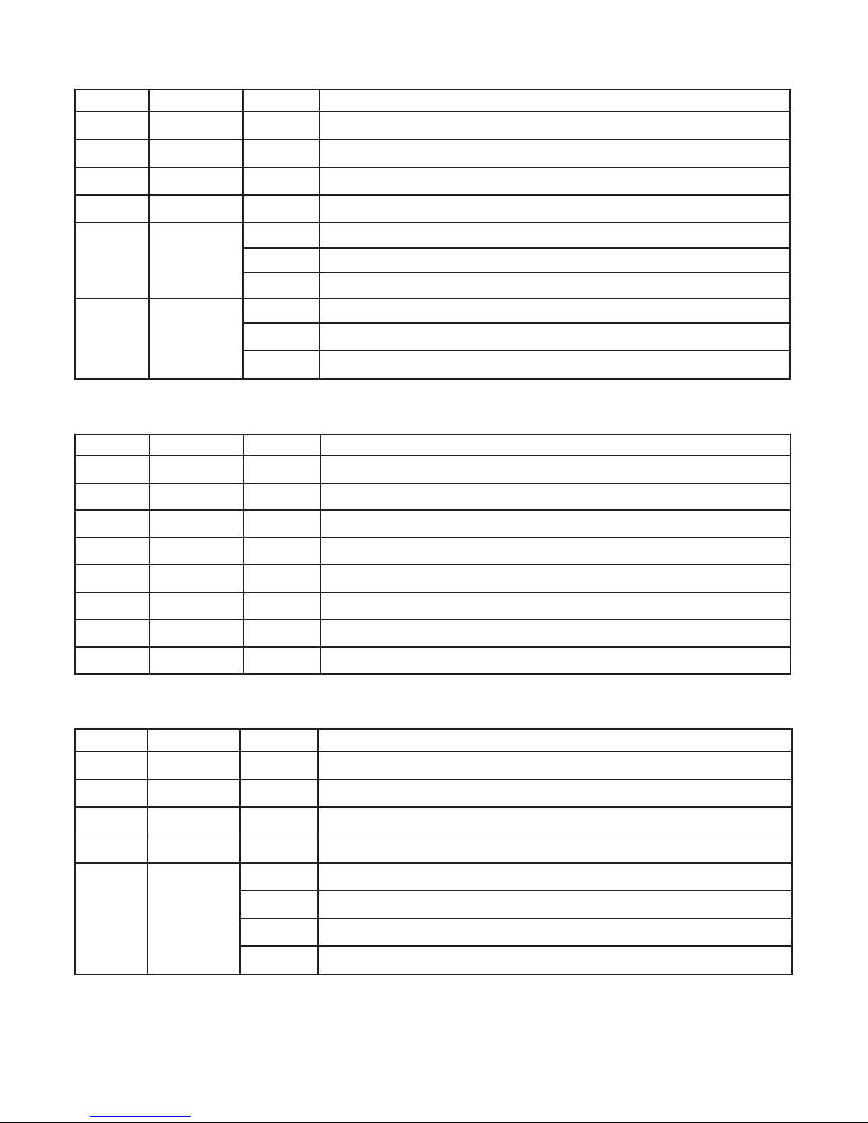
Canale Funzione Valore Descrizione
1 Rosso 0-255 Controllo proporzionale 0-100% del colore Rosso
2 Verde 0-255 Controllo proporzionale 0-100% del colore Verde
3 Blu 0-255 Controllo proporzionale 0-100% del colore Verde
4 Bianco 0-255 Controllo proporzionale 0-100% del colore Bianco
5 Dimmer
0-5 Intensità luminosa 0%
6-250 Controllo proporzionale intensità luminosa 0-100%
251-255 Intensità luminosa 100%
6 Strobo
0-5 Strobo disattivato
6-250 Controllo proporzionale effetto strobo 0-100%
251-255 Frequenza strobo 100%
Canale Funzione Valore Descrizione
1 Rosso 0-255 Controllo proporzionale 0-100% del colore Rosso del modulo superiore
2 Verde 0-255 Controllo proporzionale 0-100% del colore Verde del modulo superiore
3 Blu 0-255 Controllo proporzionale 0-100% del colore Blu del modulo superiore
4 Bianco 0-255 Controllo proporzionale 0-100% del colore Bianco del modulo superiore
5 Rosso 0-255 Controllo proporzionale 0-100% del colore Rosso del modulo inferiore
6 Verde 0-255 Controllo proporzionale 0-100% del colore Verde del modulo inferiore
7 Blu 0-255 Controllo proporzionale 0-100% del colore Blu del modulo inferiore
8 Bianco 0-255 Controllo proporzionale 0-100% del colore Bianco del modulo inferiore
Canale Funzione Valore Descrizione
1 Rosso 0-255 Controllo proporzionale 0-100% del colore Rosso del modulo superiore
2 Verde 0-255 Controllo proporzionale 0-100% del colore Verde del modulo superiore
3 Blu 0-255 Controllo proporzionale 0-100% del colore Blu del modulo superiore
4 Bianco 0-255 Controllo proporzionale 0-100% del colore Bianco del modulo superiore
5
Dimmer
Strobo
0-15 Intensità luminosa 100% del modulo superiore
16-150 Controllo proporzionale intensità luminosa 100-0% del modulo superiore
151-160 Intensità luminosa 0% del modulo superiore
161-255 Controllo proporzionale effetto strobo 0-100% del modulo superiore
Italiano 11
6.3.6 Funzioni DMX con modalità 12 canali
Canale Funzione Valore Descrizione
6 Rosso 0-255 Controllo proporzionale 0-100%del colore Rosso del modulo inferiore
7 Verde 0-255 Controllo proporzionale 0-100% del colore Verde del modulo inferiore
8 Blu 0-255 Controllo proporzionale 0-100% del colore Blu del modulo inferiore
9 Bianco 0-255 Controllo proporzionale 0-100% del colore Bianco del modulo inferiore
10
Dimmer
Strobo
0-15 Intensità luminosa 100% del modulo inferiore
16-150 Controllo proporzionale 0-100% intensità luminosa del modulo inferiore
151-160 Intensità luminosa 0% del modulo inferiore
161-255 Controllo proporzionale 0-100% effetto strobo del modulo inferiore
Canale Funzione Valore Descrizione
1 Rosso 0-255 Controllo proporzionale 0-100% del colore Rosso del modulo superiore
2 Verde 0-255 Controllo proporzionale 0-100% del colore Verde del modulo superiore
3 Blu 0-255 Controllo proporzionale 0-100% del colore Blu del modulo superiore
4 Bianco 0-255 Controllo proporzionale 0-100% del colore Bianco del modulo superiore
5 Dimmer
0-5 Intensità luminosa 0% del modulo superiore
6-250 Controllo proporzionale 0-100% intensità luminosa del modulo superiore
251-255 Intensità luminosa 100% del modulo superiore
6 Strobo
0-5 Strobo del modulo superiore disattivato
6-250 Controllo proporzionale 0-100% effetto strobo del modulo superiore
251-255 Frequenza strobo 100% del modulo superiore
7 Rosso 0-255 Controllo proporzionale 0-100% del colore Rosso del modulo inferiore
8 Verde 0-255 Controllo proporzionale 0-100% del colore Verde del modulo inferiore
9 Blu 0-255 Controllo proporzionale 0-100% del colore Blu del modulo inferiore
10 Bianco 0-255 Controllo proporzionale 0-100% del colore Bianco del modulo inferiore
11 Dimmer
0-5 Intensità luminosa 0% del modulo inferiore
6-250 Controllo proporzionale intensità luminosa 0-100% del modulo inferiore
251-255 Intensità luminosa 100% del modulo inferiore
12 Strobo
0-5 Strobo del modulo inferiore disattivato
6-250 Controllo proporzionale 0-100% effetto strobo del modulo inferiore
251-255 Frequenza strobo 100% del modulo inferiore
12 Italiano
6.4 Funzioni DMX bianco dinamico
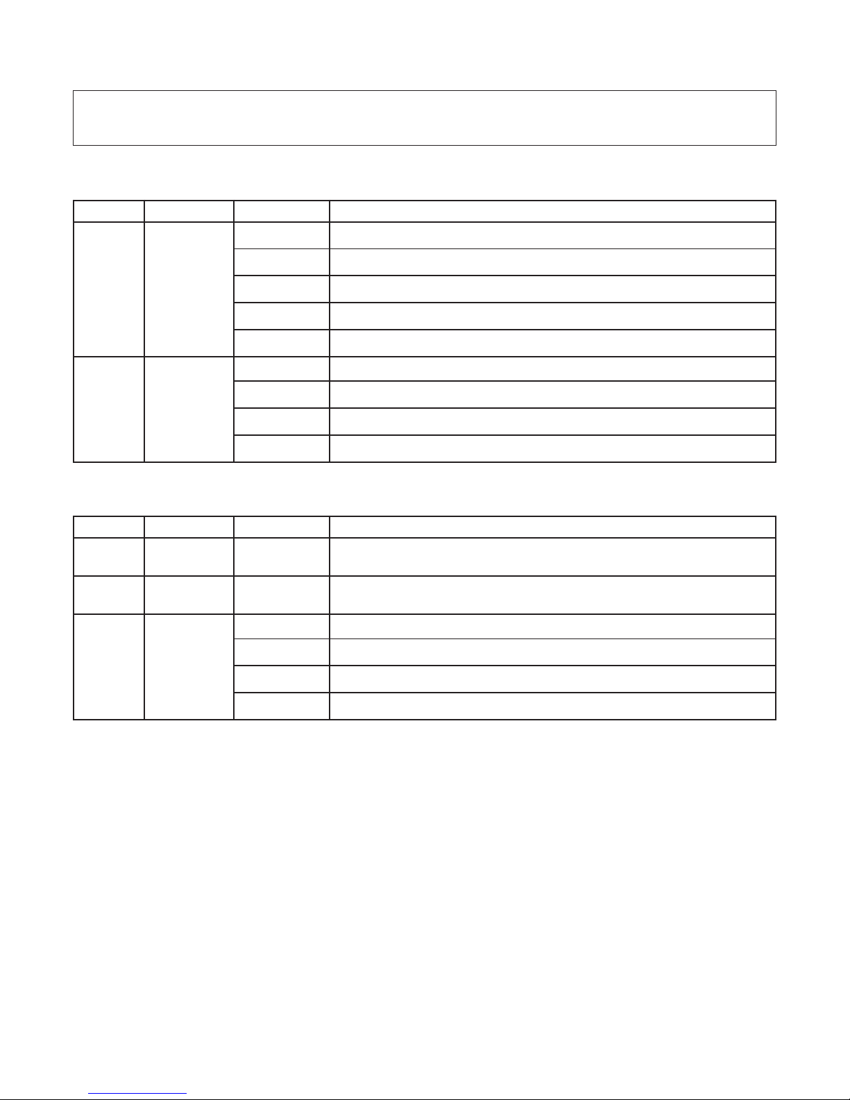
6.4.1 Funzioni DMX con modalità 2 canali
6.4.2 Funzioni DMX con modalità 3 canali
Attenzione!
In assenza del segnale DMX i led rimarranno ACCESI.
Canale Funzione Valore Descrizione
1
Bianco
dinamico
0-3 Bianco caldo 100% - Bianco freddo 0%
4-122 Bianco caldo 100% - Bianco freddo da 0% a 100%
123-132 Bianco caldo 100% - Bianco freddo 100%
133-251 Bianco caldo da 100% a 0% - Bianco freddo 100%
252-255 Bianco caldo 0% - Bianco freddo 100%
2
Dimmer
Strobo
0-15 Intensità luminosa 100%
16-150 Controllo proporzionale intensità luminosa 100-0%
151-160 Intensità luminosa 0%
161-255 Controllo proporzionale effetto strobo 0-100% (255=max)
Canale Funzione Valore Descrizione
1
Bianco
caldo
0-255 Controllo proporzionale 0-100% del bianco caldo
2
Bianco
freddo
0-255 Controllo proporzionale 0-100% del bianco freddo
3
Dimmer
Strobo
0-15 Intensità luminosa 100%
16-150 Controllo proporzionale intensità luminosa 100-0%
151-160 Intensità luminosa 0%
161-255 Controllo proporzionale effetto strobo 0-100% (255=max)

Italiano 13
6.4.3 Funzioni DMX con modalità 4 canali
Canale Funzione Valore Descrizione
1
Bianco
dinamico
0-3 Bianco caldo 100% - Bianco freddo 0% del modulo superiore
4-122
Bianco caldo 100% - Bianco freddo da 0% a 100% del modulo
superiore
123-132 Bianco caldo 100% - Bianco freddo 100% del modulo superiore
133-251
Bianco caldo da 100% a 0% - Bianco freddo 100% del modulo
superiore
252-255 Bianco caldo 0% - Bianco freddo 100% del modulo superiore
2
Dimmer
Strobo
0-15 Intensità luminosa 100% del modulo superiore
16-150
Controllo proporzionale intensità luminosa 100-0% del modulo
superiore
151-160 Intensità luminosa 0% del modulo superiore
161-255
Controllo proporzionale effetto strobo 0-100% (255=max) del modulo
superiore
3
Bianco
dinamico
0-3 Bianco caldo 100% - Bianco freddo 0% del modulo inferiore
4-122
Bianco caldo 100% - Bianco freddo da 0% a 100% del modulo
inferiore
123-132 Bianco caldo 100% - Bianco freddo 100% del modulo inferiore
133-251
Bianco caldo da 100% a 0% - Bianco freddo 100% del modulo
inferiore
252-255 Bianco caldo 0% - Bianco freddo 100% del modulo inferiore
4
Dimmer
Strobo
0-15 Intensità luminosa 100% del modulo inferiore
16-150
Controllo proporzionale intensità luminosa 100-0% del modulo
inferiore
151-160 Intensità luminosa 0% del modulo inferiore
161-255
Controllo proporzionale effetto strobo 0-100% (255=max) del modulo
inferiore

14 Italiano
6.4.4 Funzioni DMX con modalità 6 canali
6.5 Funzioni DMX monocromatico
6.5.1 Funzioni DMX con modalità 1 canale
6.5.2 Funzioni DMX con modalità 2 canali
Canale Funzione Valore Descrizione
1
Bianco
caldo
0-255
Controllo proporzionale 0-100% del bianco caldo del modulo
superiore
2
Bianco
freddo
0-255
Controllo proporzionale 0-100% del bianco freddo del modulo
superiore
3
Dimmer
Strobo
0-15 Intensità luminosa 100% del modulo superiore
16-150
Controllo proporzionale intensità luminosa 100-0% del modulo
superiore
151-160 Intensità luminosa 0% del modulo superiore
161-255
Controllo proporzionale effetto strobo 0-100% (255=max) del modulo
superiore
4
Bianco
caldo
0-255
Controllo proporzionale 0-100% del bianco caldo del modulo
inferiore
5
Bianco
freddo
0-255
Controllo proporzionale 0-100% del bianco freddo del modulo
inferiore
6
Dimmer
Strobo
0-15 Intensità luminosa 100% del modulo inferiore
16-150
Controllo proporzionale intensità luminosa 100-0% del modulo
inferiore
151-160 Intensità luminosa 0% del modulo inferiore
161-255
Controllo proporzionale effetto strobo 0-100% (255=max) del modulo
inferiore
Attenzione!
In assenza del segnale DMX i led rimarranno ACCESI.
Canale Funzione Valore Descrizione
1
Dimmer
Strobo
0-15 Intensità luminosa 100%
16-150 Controllo proporzionale intensità luminosa 100-0%
151-160 Intensità luminosa 0%
161-255 Controllo proporzionale effetto strobo 0-100% (255=max)
Canale Funzione Valore Descrizione
1
Dimmer
Strobo
0-15 Intensità luminosa 100% del modulo superiore
16-150 Controllo proporzionale intensità luminosa 100-0% del modulo superiore
151-160 Intensità luminosa 0% del modulo superiore
161-255 Controllo proporzionale effetto strobo 0-100% del modulo superiore
2
Dimmer
Strobo
0-15 Intensità luminosa 100% del modulo inferiore
16-150 Controllo proporzionale 0-100% intensità luminosa del modulo inferiore
151-160 Intensità luminosa 0% del modulo inferiore
161-255 Controllo proporzionale 0-100% effetto strobo del modulo inferiore

Italiano 15
Il proiettore Powershine MK2 D è in grado di funzionare senza segnale DMX (modo AUTOMATICO) ed è possibile
configurarlo in modo che un solo proiettore MASTER comandi una serie di proiettori SLAVE. Questa funzione è
particolarmente utile quando si vuole far eseguire lo stesso programma a più proiettori in modo sincronizzato.
Nella seguente figura è visualizzato un esempio di architettura Master-Slave.
7.1 Configurazione AUTOMATICO
RGBW - La modalità AUTOMATICO funziona SOLO quando è impostato il funzionamento con 5 canali DMX.
DW - La modalità AUTOMATICO funziona SOLO quando è impostato il funzionamento con 3 canali DMX.
Per configurare il numero dei canali premete il tasto “MENU” fino a visualizzare “ADR”.
Premete il tasto “DOWN” fino a visualizzare “CHN” e premete “ENTER”.
Tramite i tasti “UP” e “DOWN” selezionate 5 canali. Premete ENTER per confermare.
Premete i tasti “UP” o “DOWN” fino a visualizzare “AUT” . Premete “ENTER” per confermare.
Verrà visualizzata l’opzione ACT. Premete “ENTER” e scorrete le opzioni “ON” o “OFF” per attivare o disattivare
la modalità AUTOMATICA. Premete “ENTER” per confermare.
Dopo aver attivato la funzione, premete i tasti “UP” o “DOWN” fino a visualizzare “TI”. Premete “ENTER” per confermare. Mediante questa opzione è possibile selezionare i tempi di durata delle scene colore ( in secondi).
Selezionate il valore desiderato tra 5, 10, 20 e 40 premendo il tasto “ENTER”.
Ora premendo i tasti “UP” o “DOWN” è possibile scorrere gli 8 programmi preimpostati (P1-P8).
Una volta posizionati sul programma desiderato, premete “ENTER”. Selezionate ON o OFF per attivare o disattivare il programma. Premete “ENTER” per confermare.
Ora il proiettore è in modalità AUTOMATICO e sul diplay rimarrà visualizzato “AUT”.
Per uscire dalla modalità AUTOMATICO, premete il tasto “MENU”, selezionate l’opzione ACT, selezionate OFF e
confermate con “ENTER”.
7.0 MASTER-SLAVE e AUTOMATICO (solo RGBW e DW)
MASTER SLAVE 1 SLAVE N
INOUTINOUT
SLAVE 2
INOUT OUT
Terminale
R=120
ƺ
non inclusa!)
Attenzione!
E’ possibile selezionare più programmi che verranno eseguiti in sequenza.
Se state utilizzando la modalità MASTER-SLAVE o AUTOMATICO, il proiettore NON può essere contollato da
una centralina DMX e sulla linea non devono essere presenti altri dispositivi di controllo!!

Nella seguente tabella sono riportati i colori visualizzati nei vari programmi (solo RGBW).
7.2 Configurazione MASTER
Per impostare il proiettore come MASTER si eseguono le stesse operazioni utilizzate per l’impostazione come
AUTOMATICO (vedi paragrafo Configurazione AUTOMATICO).
7.3 Configurazione SLAVE
Per impostare il proiettore come SLAVE impostare il funzionamento in modalità DMX a 5 canali (RGBW) o 3 canali (bianco dinamico) con indirizzo 001.
Nella modalità COLORI FISSI, è possibile accendere manualmente i led, senza l’utilizzo di una centralina DMX.
In questa modalità il proiettore si comporta anche da MASTER e può controllare una serie di proiettori SLAVE
8.1 Configurazione MASTER RGBW
La modalità COLORI FISSI funziona SOLO quando è impostato il funzionamento con 5 canali DMX.
Per configurare il proiettore in modalità COLORI FISSI premete il tasto “MENU” fino a visualizzare “ADR”.
Premete i tasti “UP” o “DOWN” fino a visualizzare “COL” . Premete “ENTER” per confermare.
Verrà visualizzata l’opzione ACT. Premendo ENTER e scorrete le opzioni “ON” o “OFF” per attivare o disattivare
la modalità COLORI FISSI. Premete “ENTER” per confermare.
Ora premendo i tasti “UP” o “DOWN” è possibile scorrere i colori:
1. Rosso RED
2. Verde GRE
3. Blu BLU
4. Bianco UHT
Una volta posizionati sul colore desiderato, premete “ENTER”. Selezionate ON o OFF per attivare o disattivare il colore. Premete “ENTER” per confermare.
Ora il proiettore è in modalità COLORI FISSI e sul diplay rimarrà visualizzato “COL”.
Per uscire dalla modalità COLORI FISSI, premete il tasto “MENU”, selezionate l’opzione ACT, selezionate OFF e
confermate con “ENTER”.
8.2 Configurazione MASTER DW
La modalità COLORI FISSI funziona SOLO quando è impostato il funzionamento con 3 canali DMX.
Per configurare il proiettore in modalità COLORI FISSI premete il tasto “MENU” fino a visualizzare “ADR”.
Premete i tasti “UP” o “DOWN” fino a visualizzare “COL” . Premete “ENTER” per confermare.
Verrà visualizzata l’opzione ACT. Premendo ENTER e scorrete le opzioni “ON” o “OFF” per attivare o disattivare
la modalità COLORI FISSI. Premete “ENTER” per confermare.
Ora premendo i tasti “UP” o “DOWN” è possibile scorrere i colori:
1. Bianco freddo CW
2. Bianco caldo WW
Una volta posizionati sul colore desiderato, premete “ENTER”. Selezionate ON o OFF per attivare o disattivare il
colore. Premete “ENTER” per confermare.
Ora il proiettore è in modalità COLORI FISSI e sul diplay rimarrà visualizzato “COL”.
Per uscire dalla modalità COLORI FISSI, premete il tasto “MENU”, selezionate l’opzione ACT, selezionate OFF e
confermate con “ENTER”.
8.3 Configurazione SLAVE
Per impostare il proiettore come SLAVE impostare il funzionamento in modalità DMX a 5 canali (RGBW) o 3 ca-
nali (bianco dinamico) con indirizzo 001.
N° Programma Effetto
1 Rosso - Magenta - Giallo
2 Rosso - Magenta - Giallo - Bianco
3 Verde - Ciano - Giallo
4 Verde - Ciano - Giallo - Bianco
5 Blu - Ciano - Magenta
6 Blu - Ciano - Magenta - Bianco
7 Verde - Ciano - Blu - Magenta - Rosso - Giallo
8 Verde - Ciano - Blu - Magenta - Rosso - Giallo - Bianco
8.0 Funzionamento in modalità COLORI FISSI (solo RGBW e DW)
16 Italiano

Mediante questa funzione è possibile regolare la luminosità dei LED.
Per attivare la funzione premete il tasto “MENU” fino a visualizzare “ADR”. Premete i tasti “UP” o “DOWN” fino a
visualizzare “DIM” . Premete “ENTER” per confermare. Comparirà il valore DMX della funzione dimmer. Premete i
tasti “UP” o “DOWN” fino a visualizzare il valore desiderato, quindi premere ENTER.
Mediante questa funzione è possibile verificare la temperatura di funzionamento dei led.
Per visualizzare la temperatura premete il tasto “MENU” fino a visualizzare “ADR”. Premete i tasti “UP” o “DOWN”
fino a visualizzare “TEM” . Premete “ENTER” per confermare. Comparirà il valore della temperatura di funzionamento dei LED che non dovrà mai essere superiore ai 75°C. Un valore più elevato evidenzia un malfunzionamento dell’apparecchiatura.
Mediante questa funzione è possibile verificare la temperatura di funzionamento dei driver dei led.
Per visualizzare la temperatura premete il tasto “MENU” fino a visualizzare “ADR”. Premete i tasti “UP” o “DOWN”
fino a visualizzare “DRT” . Premete “ENTER” per confermare. Comparirà il valore della temperatura di funzionamento dei LED che non dovrà mai essere superiore ai 70°C. Un valore più elevato evidenzia un malfunzionamento dell’apparecchiatura.
Mediante questa funzione è possibile verificare la temperatura del corpo proiettore.
Per visualizzare la temperatura premete il tasto “MENU” fino a visualizzare “ADR”. Premete i tasti “UP” o “DOWN”
fino a visualizzare “BOT” . Premete “ENTER” per confermare.
Mediante questa funzione è possibile verificare la percentuale di potenza che viene fornita al riscaldatore.
Per visualizzare la temperatura premete il tasto “MENU” fino a visualizzare “ADR”. Premete i tasti “UP” o “DOWN”
fino a visualizzare “HEP” . Premete “ENTER” per confermare.
Mediante questa funzione è possibile impostare TUTTI i parametri ai valori di default.
Per attivare la funzione premete il tasto “MENU” fino a visualizzare “ADR”.
Premete i tasti “UP” o “DOWN” fino a visualizzare “DEF” . Premete “ENTER” per confermare.
Selezionate “RES” o “CAN” per resettare i valori o cancellare l’operazione.
Verranno impostati ai valori di default i seguenti parametri: indirizzo dmx, numero di canali dmx, modalità Automatica, modalità colore.
9.0 Dimmer (solo monocromatico)
10.0 Temperatura dei led
11.0 Temperatura dei driver dei led
12.0 Temperatura del corpo (solo versioni Polar)
13.0 Potenza del riscaldatore (solo versioni Polar)
14.0 Impostazioni di default
Italiano 17

Nella modalità DMX, il proiettore è in grado di accettare i seguenti comandi RDM:
• discovery
Su richiesta del controller RDM, il proiettore segnala la sua presenza (il controller RDM visualizzerà il faro in un
elenco).
• lettura/impostazione indirizzo DMX.
• lettura/impostazione del numero di canali utilizzato.
• identificazione ON/OFF
Questo comando serve ad identificare il faro al quale si vuole accedere (l'identificazione avviene accendendo
tutti i led con luminosità massima).
• visualizzazione costruttore
Viene visualizzato il nome del costruttore dell’apparecchio (Griven).
• descrizione modello
Viene visualizzato il modello dell’apparecchio.
• descrizione versione software
Viene visualizzato la versione del firmware in uso sull’apparecchio.
• visualizzazione temperatura
Viene visualizzato il valore della temperatura di funzionamento dei led.
Un sensore termico, all’interno, protegge il proiettore dal surriscaldamento. Il sensore termico limita la corrente ai
led, per salvaguardarne l’integrità, nel caso la temperatura ambiente sia superiore a quella consentita.
Nella versione POLAR, il proiettore è dotato di un particolare vetro riscaldato utile per applicazioni in ambienti
esterni e particolarmente freddi, infatti, scaldandosi il vetro scioglie ghiaccio e neve, che altrimenti impedirebbero la proiezione.
Alimentando il proiettore, se la temperatura lo richiede, si scalda il vetro termico, che rimane attivo fino al
raggiungimento della temperatura di esercizio.
In caso di proiezioni temporizzate (da iniziare ad orari definiti), si consiglia di alimentare il proiettore con sufficiente
anticipo per permettere lo sbrinamento del vetro e di accendere poi i led solo all’orario stabilito.
Con temperature esterne particolarmente rigide (sotto i -20°C), consigliamo di lasciare il proiettore sempre
alimentato e accendere i led al momento del bisogno.
Per assicurare la massima funzionalità e resa ottica. si raccomanda di attenersi alle istruzioni riportate qui di seguito.
18.1 Pulizia del proiettore
Il proiettore deve essere pulito regolarmente. La frequenza della pulizia dipende soprattutto dall’ambiente nel
quale l’apparecchiatura funziona, infatti polvere eccessiva, depositi di fumo ed altre scorie riducono le prestazioni ottiche.
• Pulite regolarmente il vetro del proiettore
• Prestare molta attenzione durante la pulizia dei componenti ed assicurarsi di lavorare in un ambiente pulito e
ben illuminato.
• Non usare solventi che potrebbero danneggiare o le superfici verniciate.
• Rimuovere la polvere con un panno di cotone inumidito con pulitore per vetri o acqua distillata.
• Rimuovere fumo ed altri residui con un panno di cotone inumidito con alcol isopropile.
• Asciugare con un panno pulito, soffice e privo di filamenti, oppure con aria compressa.
15.0 Funzioni RDM
16.0 Protezione termica
17.0 Vetro no-frost
18.0 Manutenzione
Attenzione!
Togliete tensione prima di effettuare qualsiasi operazione sul proiettore.
18 Italiano

18.2 Controlli periodici
• Controllate i collegamenti elettrici ed in particolare la messa a terra ed il cavo di alimentazione.
• Controllate che il proiettore non sia danneggiato meccanicamente ed eventualmente sostituite le parti deteriorate.
18.3 Coppie di serraggio
In caso di apertura del corpo proiettore o delle scatole posteriori, le viti del supporto vetro devono essere serrate
con una coppia di 4Nm, mentre quelle delle scatole posteriori, con una coppia di 2.5Nm.
Tutti i componenti del proiettore sono disponibili come parti di ricambio presso i rivenditori Griven.
Le viste esplose, lo schema elettrico e il diagramma elettronico sono disponibili su richiesta.
Per facilitare il lavoro del centro di assistenza ricordate di specificare il numero di serie ed il modello del proiettore di cui avete richiesto i ricambi.
La direttiva Europea 2002/96/CE sui rifiuti di apparecchiature elettroniche (RAEE), prevede che gli apparecchi
illuminanti non debbano essere smaltiti nel normale flusso dei rifiuti solidi urbani. Gli apparecchi dismessi debbono
essere raccolti separatamente per ottimizzare il tasso di recupero e riciclaggio dei materiali che li compongono
ed impedire potenziali danni per la salute e l’ambiente.
Il simbolo del cestino barrato è riportato su tutti i prodotti per ricordare gli obblighi di raccolta separata.
Per ulteriori informazioni sulla corretta dismissione delle apparecchiature, i detentori potranno rivolgersi al servizio
pubblico preposto o ai rivenditori.
19.0 Parti di ricambio
20.0 Smaltimento dell’apparecchiatura
21.0 Ricerca dei guasti
Problema Possibile causa Provvedimento
Il proiettore non
risponde correttamente
al controllo DMX.
Collegamento cavi
DMX non corretto.
Ispezionare connessioni e cavi. Correggere le connessioni
inefficienti. Riparare o sostituire i cavi danneggiati.
Collegamento dati non
terminato.
Inserire una spina di termine nel jack di uscita
dell’ultima apparecchiatura del collegamento.
Scorretta assegnazione di
indirizzi dei proiettori.
Controllare gli indirizzi delle apparecchiature e le
impostazioni del protocollo.
Una delle apparecchiature
è difettosa e disturba la
trasmissione di dati nel
collegamento.
Cortocircuitare un’apparecchiatura alla volta
fino a quando il funzionamento normale non è
ripristinato.
E’ stato impostato un modo
di funzionamento diverso
dalla modalità DMX utilizzata.
Verificate il modo di funzionamento impostato.
Controllate la tabella funzioni DMX corrispondente.
Il proiettore è configurato
come Master , ma non esegue nessun programma.
E’ stata attivata la funzione
Master, ma non è stato selezionato nessun programma.
Selezionare almeno un programma da eseguire.
Il proiettore è configurato
come Slave , ma non
risponde correttamente
al Master.
Sono stati impostati più
Master sulla linea
Verificare che solo un’apparecchio sia configurato
come Master.
Sulla linea è presente il
segnale DMX.
Verificare che non ci siano centraline DMX sulla linea.
Italiano 19

20 English
Caratteristiche meccaniche
Altezza . . . . . . . . . . . . . . . . . . . . . . . . . . . . . . . . . . . . . . . . . . . . . . . . . . . . . . . . . . . . . . . . . . . . . . . . . . . . . .696mm (27.4”)
Larghezza . . . . . . . . . . . . . . . . . . . . . . . . . . . . . . . . . . . . . . . . . . . . . . . . . . . . . . . . . . . . . . . . . . . . . . . . . . .567mm (22.3”)
Profondità . . . . . . . . . . . . . . . . . . . . . . . . . . . . . . . . . . . . . . . . . . . . . . . . . . . . . . . . . . . . . . . . . . . . . . . . . . . .191mm (7.5”)
Peso . . . . . . . . . . . . . . . . . . . . . . . . . . . . . . . . . . . . . . . . . . . . . . . . . . . . . . . . . . . . . . . . . . . . . . . . . . . . . . . .41Kg (90.4Lbs)
Caratteristiche termiche
Massima temperatura ambiente . . . . . . . . . . . . . . . . . . . . . . . . . . . . . . . . . . . . . . . . . . . . . . . . . . . . . . . . . .50°C (122°F)
Minima temperatura ambiente . . . . . . . . . . . . . . . . . . . . . . . . . . . . . . . . . . . . . . . . . . . . . . . . . . . . . . . . . .-40°C (-104°F)
Massima temperatura superficiale . . . . . . . . . . . . . . . . . . . . . . . . . . . . . . . . . . . . . . . . . . . . . . . . . . . . . <70°C ( <158°F)
Caratteristiche elettriche
Tensione di alimentazione . . . . . . . . . . . . . . . . . . . . . . . . . . . . . . . . . . . . . . . . . . . . . . . . . . . . . . . . 100-277 Vac 50/60Hz
Corrente nominale . . . . . . . . . . . . . . . . . . . . . . . . . . . . . . . . . . . . . . . . . . . . . . . . . . . . . . . . . . . . . . . . . . . . . .2.6A @ 230V
Potenza massima . . . . . . . . . . . . . . . . . . . . . . . . . . . . . . . . . . . . . . . . . . . . . . . . . . . . . . . . . . . . . . . . . . . . . . . . . . . . .576W
Protezione termica . . . . . . . . . . . . . . . . . . . . . . . . . . . . . . . . . . . . . . . . . . . . . . . . . . . . . . . . . . . . . . . . . . . . . . Elettronica
Sorgente luminosa
Tipo sorgente luminosa . . . . . . . . . . . . . . . . . . . . . . . . . . . . . . . . . . . . . . . . . . . . . . . . . . . . . . . . . . . . . . . . . . . . . .192 Led
Ottica
Sistema ottico . . . . . . . . . . . . . . . . . . . . . . . . . . . . . . . . . . . . . . . . . . . . . . . . . . . . . . . . . . . . . . . . . . . . . . . . . . . . . . A lenti
Controllo
Protocollo . . . . . . . . . . . . . . . . . . . . . . . . . . . . . . . . . . . . . . . . . . . . . . . . . . . . . . . . . . . . . . . . . . . . . . . . . . . USITT DMX-512
Canali di controllo RGBW . . . . . . . . . . . . . . . . . . . . . . . . . . . . . . . . . . . . . . . . . . . . . . . . 4 - 5 - 6 - 8 - 10 - 12 canali DMX
Canali di controllo DW . . . . . . . . . . . . . . . . . . . . . . . . . . . . . . . . . . . . . . . . . . . . . . . . . . . . . . . . . 2 - 3 - 4 - 6 canali DMX
Canali di controllo MONO . . . . . . . . . . . . . . . . . . . . . . . . . . . . . . . . . . . . . . . . . . . . . . . . . . . . . . . . . . . 1 - 2 canali DMX
Costruzione
Corpo proiettore . . . . . . . . . . . . . . . . . . . . . . . . . . . . . . . . . . . . . . . . . . . . . . . . . . . . . . . . . . . . . . . . . . Acciaio/Alluminio
Trattamento . . . . . . . . . . . . . . . . . . . . . . . . . . . . . . . . . . . . . . . . . . . . . . . . . . . . . . . . . . . . . . . . . . . . . Vernice antigraffio
Fattore di protezione . . . . . . . . . . . . . . . . . . . . . . . . . . . . . . . . . . . . . . . . . . . . . . . . . . . . . . . . . . . . . . . . . . . . . . . . . . . IP66
22.0 Specifiche tecniche

English 21
1.1 Safety information
1.1.1 Protecting against electric shock
• Disconnect the unit from mains supply before servicing it or performing any other action.
• Always ground/earth the unit electrically.
• Before connecting the unit to power supplies, verify that operating voltage and frequency are compatible.
• Do not handle the unit with wet hands or in the presence of water.
• Check regularly that the power supply cable is not damaged or crushed.
• Apply to a qualified technician for any regular maintenance action not described in this manual.
1.1.2 Installation
• Fix the unit with screws, hooks or any other support able to bear the weight of the unit itself.
• The unit installation actions must be performed by a qualified staff.
1.1.3 Protection against burns and fire
• Suitable to be installed onto normally inflammable surfaces.
• The unit is not to be installed in places where the ambient temperature exceeds 50° (122°F).
1.1.4 Weather protection
The unit is classified as device with an IP66 weather protection rate.
1.2 Warranty conditions
• Each product manufactured by GRIVEN srl of Italy is assembled and built in accordance to current CE conformity rules and regulations.
• Every single product and component has been tested before the final assembling and all products must pass
the in-house quality control before they are shipped.
• GRIVEN srl of Italy guarantees the good quality and manufacture of the products and undertakes to repair or
supply again, according to his opinion and free of charge, within the shortest time possible, any part that shows
- during the guarantee period - defects of constructions, manufacture or material.
• The guarantee is valid for 12 (twelve) months starting from the delivery date of the products.
• GRIVEN srl of Italy does not respond for damages occurred to the units during transport and for irrational use and
inaccuracy in regular maintenance of the products.
• The guarantee excludes all consumables.
• The customer will take care of the return of the faulty parts to GRIVEN srl of Italy, at his own charge and risk.
• The parts which have been repaired or replaced are sent by GRIVEN srl of Italy ex-factory.
• For any dispute, the Court of Mantova (Italy) will be competent and in conformity with relevant jurisdiction the
Italian Law is enforced for any controversy.
1.3 Compliance
• Product in compliance with EN60598-1 EN60598-2-17.
• Product in compliance with 2002/95/CE (RoHS).
1.0 Introduction
Warning!
This unit is suitable for professional use only, not for domestic use.

22 English
3.1 Packaging
Check carefully the content of the box and, in case of damage, contact your forwarder immediately. The following items are included in the box of this unit:
n° 1 Powershine MK2 D unit
n° 1 owner’s manual
n° 2 connection kit
3.2 Transport
The carton box has not been designed to be used more than once, therefore, it is recommended to use one of
our flight cases to transport the unit.
2.0 Size
696mm
27,41in
567mm
22,32in
334mm
13,16in
682mm
26,85in
1
2
.5m
m
0,
5i
n
150mm
5,91in
300mm
1
1,
81i
n
3.0 Packaging and transport
Warning!
• Griven S.r.l. liability will cease upon consignment of goods to the forwarder: claims for damage due to transport must be addressed directly to the forwarder.
• Griven S.r.l. will accept claims for broken or missing goods only within seven days of receipt of the goods.
• Returns of equipment will not be accepted without prior authorization granted by Griven S.r.l. and if not duly accompanied by relevant shipping documents.

English 23
4.1 Fixing
The unit can be used both rested on floor and fixed onto a structure. The unit can operate in any position.
Use the holes Ø12.5 (1/2”) or Ø6.5 (1/4”) in the bracket to fix the
unit.
4.2 Adjusting light beam direction
1. Untighten the lateral screw “3”.
2. Rotate the bodies of the unit towards desired direction and
tighten the screw “3”.
4.0 Installation
1
2
.
5
m
m
0
,
5
i
n
150mm
5,91in
3
0
0
mm
1
1
,
8
1
i
n
3
3

24 English
4.3 Connection to mains power
The unit can operate with voltage from 100-277Vac and with frequency of 50 and 60Hz.
For the connection use main cable in the side of the rear boxl of the fixture and connect as shown below.
4.4 Connection to DMX signal
The DMX signal is to be connected by using a shielded cable designed for devices RS-485.
The signal cable must be connected according to the following table:
GND = Shield
DATA - = Black
DATA + = Red
The projector is fitted with butt connectors and heat shrink tube which allow to perform IP67 connections.
To make the connection follow these instructions.
Warning!
• Before connecting the unit, verify that power supplies features are compatible with the unit features.
• The unit must never be installed if not grounded electrically.
• It is suggested to use a magnetothermic switch along the power supply line, as prescribed by in force rules.
• The unit must not be powered up through a dimmer power device.
• Wiring and connection actions are to be performed by a qualified staff.
Live
Ground
Neutral
Brown
Yellow Green
Blue
Main supply
Warning!
Follow the instructions provided along with the connection kit to perform the connections.
Warning!
All data wires must be isolated one from another and from the shield.
The GND of the DMX signal is not to be connected to the electric ground of the unit.
Insert a terminal plug with a 120 Ω resistor connected to DATA- and DATA+ in the last unit.
Warning!
Follow the instructions provided along with the connection kit to perform the connections.

English 25
5.1 Setting operating mode
By the control panel it is possible to select one of the following operating modes:
• using DMX512 signal control mode
Each fixture is controlled from DMX512 signal control.
(see chapter 8.0 DMX function)
• MASTER-SLAVE or AUTOMATIC mode (only RGBW and DW)
The projector operates independently, without DMX512 signal control.
(see chapter MASTER/SLAVE and AUTOMATIC function)
• using FIXED COLOURS mode (only RGBW and DW)
The projector operates independently, without DMX512 signal control.
(see chapter FIXED COLOURS function)
The unit NORMALLY works in DMX mode and, on turning on, the display will read the number of DMX address (e.g.
012).
If on turning on the display will read “AUT”, it will mean that the unit is working in AUTOMATIC mode.
Disable this function to go back to the DMX mode.
If on turning on, the display will read “COL”, it will mean that the unit is working in FIXED COLOURS mode.
Disable this function to go back to the DMX mode.
5.2 Unit control panel
The display of the unit is programmed to turn off
automatically after 10 seconds of non working.
To activate it just press any key.
In the presence of the DMX signal the red led will steadily
be on while in the absence of DMX signal the led will flash.
The SET led is on during:
• DMX address is setting
• menu setting
5.2.1 Reading the display and using controls
MENU button:
By pushing the “MENU” button the display will show the main menu or you can exit from function and go back to
main menu.
By pushing the “MENU” button when is show the DMX address, you will enter in the main menu.
• Address setting ADR
• Channels number setting CHN (only RGBW and DW)
• MASTER/SLAVE and AUTOMATIC mode AUT (only RGBW and DW)
• FIXED COLOURS mode COL (only RGBW and DW)
• Dimmer whitout DMX DIM ( only monochrome)
• LED temperature LET
• Driver temperature DRT
• Body temperature BOT ( only Polar version)
• Heating Power HEP ( only Polar version)
• Default settings DEF
• Release software REL
UP and DOWN buttons:
By pushing the “UP” and “DOWN” buttons, values of the function which is shown in the display can be changed.
ENTER button:
Keep the “ENTER” button pushed, until the display and the SET led flash, in order to memorize the function which
5.0 Use of the unit

26 English
is shown on the display.
6.1 Setting DMX channels
The number of DMX channels used by the unit to operate will depend from the selected operating mode.
Each RGBW unit will use 4, 5, 6, 8, 10, 12 DMX channels.
Each DW unit will use 2, 3, 4, 6 DMX channels.
Each monochrome unit will use 1 o 2 DMX channels.
Follow this description to modify the DMX channels setting: press the “MENU” button, select “CHN” and press
“ENTER” button to activate the function. Then select the desired value (1C/../12C) through the “UP” and “DOWN”
keys. Press “ENTER” to confirm.
6.2 Setting DMX address
Follow this description to modify the address: press once the “MENU” button, select “ADR” and press “ENTER” button to activate the function. Then select the desired value (between 1 and 512 ) through the “UP” and “DOWN”
keys. Press “ENTER” to confirm.
6.3 DMX functions RGBW
6.3.1 DMX functions with DMX MODE = 4 channels
6.3.2 DMX functions with DMX MODE = 5 channels
6.0 DMX function mode
Warning!
In absence of DMX signal the led will remain OFF.
Channel Function Value Description
1 Red 0-255 Proportional control 0-100% of the Red color
2 Green 0-255 Proportional control 0-100% of the Green color
3 Blue 0-255 Proportional control 0-100% of the Blue color
4 White 0-255 Proportional control 0-100% of the White color
Channel Function Value Description
1 Red 0-255 Proportional control 0-100% of the Red color
2 Green 0-255 Proportional control 0-100% of the Green color
3 Blue 0-255 Proportional control 0-100% of the Blue color
4 White 0-255 Proportional control 0-100% of the White color
5
Dimmer
Strobe
0-15 Luminous output intensity 100%
16-150 Proportional control of the luminous output intensity 100-0%
151-160 Luminous output intensity 0%
161-255 Proportional control of the strobe effect 0-100% (255=max)

English 27
6.3.3 DMX functions with DMX MODE = 6 channels
6.3.4 DMX functions with DMX MODE = 8 channels
6.3.5 DMX functions with DMX MODE = 10 channels
Channel Function Value Description
1 Red 0-255 Proportional control 0-100% of the Red color
2 Green 0-255 Proportional control 0-100% of the Green color
3 Blue 0-255 Proportional control 0-100% of the Blue color
4 White 0-255 Proportional control 0-100% of the White color
5 Dimmer
0-5 Luminous output intensity 0%
6-250 Proportional control of the luminous output intensity 0-100%
251-255 Luminous output intensity 100%
6 Strobe
0-15 No strobe
6-250 Proportional control of the strobe effect 0-100%
251-255 Strobe effect 100%
Channel Function Value Description
1 Red 0-255 Proportional control 0-100% of the Red color of the upper cluster
2 Green 0-255 Proportional control 0-100% of the Green color of the upper cluster
3 Blue 0-255 Proportional control 0-100% of the Blue color of the upper cluster
4 White 0-255 Proportional control 0-100% of the White color of the upper cluster
5 Red 0-255 Proportional control 0-100% of the Red color of the lower cluster
6 Green 0-255 Proportional control 0-100% of the Green color of the lower cluster
7 Blue 0-255 Proportional control 0-100% of the Blue color of the lower cluster
8 White 0-255 Proportional control 0-100% of the White color of the lower cluster
Channel Function Value Description
1 Red 0-255 Proportional control 0-100% of the Red color of the upper cluster
2 Green 0-255 Proportional control 0-100% of the Green color of the upper cluster
3 Blue 0-255 Proportional control 0-100% of the Blue color of the upper cluster
4 White 0-255 Proportional control 0-100% of the White color of the upper cluster
5
Dimmer
Strobe
0-15 Luminous output intensity 100% of the upper cluster
16-150
Proportional control of the luminous output intensity 100-0% of the upper
cluster
151-160 Luminous output intensity 0% of the upper cluster
161-255 Proportional control of the strobe effect 0-100% of the upper cluster

English 28
6.3.6 DMX functions with DMX MODE = 12 channels
Channel Function Value Description
6 Red 0-255 Proportional control 0-100% of the Red color of the lower cluster
7 Green 0-255 Proportional control 0-100% of the Green color of the lower cluster
8 Blue 0-255 Proportional control 0-100% of the Blue color of the lower cluster
9 White 0-255 Proportional control 0-100% of the White color of the lower cluster
10
Dimmer
Strobe
0-15 Luminous output intensity 100% of the lower cluster
16-150
Proportional control of the luminous output intensity 100-0% of the lower
cluster
151-160 Luminous output intensity 0% of the lower cluster
161-255 Proportional control of the strobe effect 0-100% of the lower cluster
Channel Function Value Description
1 Red 0-255 Proportional control 0-100% of the Red color of the upper cluster
2 Green 0-255 Proportional control 0-100% of the Green color of the upper cluster
3 Blue 0-255 Proportional control 0-100% of the Blue color of the upper cluster
4 White 0-255 Proportional control 0-100% of the White color of the upper cluster
5 Dimmer
0-5 Luminous output intensity 0% of the upper cluster
6-250
Proportional control of the luminous output intensity 0-100% of the lower
cluster
251-255 Luminous output intensity 100% of the upper cluster
6 Strobo
0-15 No strobe of the upper cluster
6-250 Proportional control of the strobe effect 0-100% of the upper cluster
251-255 Strobe effect 100% of the upper cluster
7 Red 0-255 Proportional control 0-100% of the Red color of the lower cluster
8 Green 0-255 Proportional control 0-100% of the Green color of the lower cluster
9 Blue 0-255 Proportional control 0-100% of the Blue color of the lower cluster
10 White 0-255 Proportional control 0-100% of the White color of the lower cluster
11 Dimmer
0-5 Luminous output intensity 0% of the lower cluster
6-250
Proportional control of the luminous output intensity 0-100% of the lower
cluster
251-255 Luminous output intensity 100% of the lower cluster
12 Strobo
0-15 No strobe of the lower cluster
6-250 Proportional control of the strobe effect 0-100% of the lower cluster
251-255 Strobe effect 100% of the lower cluster

6.4 DMX functions dynamic white
6.4.1 DMX functions with DMX MODE = 2 channels
6.4.2 DMX functions with DMX MODE = 3 channels
Warning!
In absence of DMX signal the led will remain ON.
Channel Function Value Description
1
Dynamic
white
0-3 Warm white 100% - Cold white 0%
4-122 Warm white 100% - Cold white from 0% to 100%
123-132 Warm white 100% - Cold white 100%
133-251 Warm white 100% to 0% - Cold white 00%
252-255 Warm white 0% - Cold white 100%%
2
Dimmer
Strobe
0-15 Luminous output intensity 100%
16-150 Proportional control of the luminous output intensity 100-0%
151-160 Luminous output intensity 0%
161-255 Proportional control of the strobe effect 0-100% (255=max)
Channel Function Value Description
1
Warm
white
0-255 Proportional control 0¬-100% of the warm white
2
Cold
white
0-255 Proportional control 0¬-100% of the cold white
3
Dimmer
Strobo
0-15 Luminous output intensity 100%
16-150 Proportional control of the luminous output intensity 100-0%
151-160 Luminous output intensity 0%
161-255 Proportional control of the strobe effect 0-100% (255=max)
English 29

6.4.3 DMX functions with DMX MODE = 4 channels
Channel Function Value Description
1
Dynamic
white
0-3 Warm white 100% - Cold white 0% (upper cluster)
4-122 Warm white 100% - Cold white from 0% to 100% (upper cluster)
123-132 Warm white 100% - Cold white 100% (upper cluster)
133-251 Warm white 100% to 0% - Cold white 00% (upper cluster)
252-255 Warm white 0% - Cold white 100%% (upper cluster)
2
Dimmer
Strobe
0-15 Luminous output intensity 100% (upper cluster)
16-150
Proportional control of the luminous output intensity 100-0%
(upper cluster)
151-160 Luminous output intensity 0% (upper cluster)
161-255
Proportional control of the strobe effect 0-100% (255=max)
(upper cluster)
3
Dynamic
white
0-3 Warm white 100% - Cold white 0% (lower cluster)
4-122 Warm white 100% - Cold white from 0% to 100% (lower cluster)
123-132 Warm white 100% - Cold white 100% (lower cluster)
133-251 Warm white 100% to 0% - Cold white 00% (lower cluster)
252-255 Warm white 0% - Cold white 100% (lower cluster)
4
Dimmer
Strobe
0-15 Luminous output intensity 100% (lower cluster)
16-150
Proportional control of the luminous output intensity 100-0%
(lower cluster)
151-160 Luminous output intensity 0% (lower cluster)
161-255
Proportional control of the strobe effect 0-100% (255=max)
(lower cluster)
30 English

6.4.4 DMX functions with DMX MODE = 6 channels
6.5 DMX functions monochrome
6.5.1 DMX functions with DMX MODE = 1 channel
6.5.2 DMX functions with DMX MODE = 2 channels
Channel Function Value Description
1
Warm
white
0-255 Proportional control 0¬-100% of the warm white (upper cluster)
2
Cold
white
0-255 Proportional control 0¬-100% of the cold white (upper cluster)
3
Dimmer
Strobo
0-15 Luminous output intensity 100% (upper cluster)
16-150
Proportional control of the luminous output intensity 100-0%
(upper cluster)
151-160 Luminous output intensity 0% (upper cluster)
161-255
Proportional control of the strobe effect 0-100% (255=max)
(upper cluster)
4
Warm
white
0-255 Proportional control 0¬-100% of the warm white (lower cluster)
5
Cold
white
0-255 Proportional control 0¬-100% of the cold white (lower cluster)
6
Dimmer
Strobo
0-15 Luminous output intensity 100% (lower cluster)
16-150
Proportional control of the luminous output intensity 100-0%
(lower cluster)
151-160 Luminous output intensity 0% (lower cluster)
161-255
Proportional control of the strobe effect 0-100% (255=max)
(lower cluster)
Warning!
In absence of DMX signal the led will remain ON.
Channel Function Value Description
1
Dimmer
Strobe
0-15 Luminous output intensity 100%
16-150 Proportional control of the luminous output intensity 100-0%
151-160 Luminous output intensity 0%
161-255 Proportional control of the strobe effect 0-100% (255=max)
Channel Function Value Description
1
Dimmer
Strobe
0-15 Luminous output intensity 100% of the upper cluster
16-150
Proportional control of the luminous output intensity 100-0% of the upper
cluster
151-160 Luminous output intensity 0% of the upper cluster
161-255 Proportional control of the strobe effect 0-100% of the upper cluster
2
Dimmer
Strobe
0-15 Luminous output intensity 100% of the lower cluster
16-150
Proportional control of the luminous output intensity 100-0% of the lower
cluster
151-160 Luminous output intensity 0% of the lower cluster
161-255 Proportional control of the strobe effect 0-100% of the lower cluster
English 31

Powershine MK2 D can operate without DMX signal (in AUTOMATIC mode) and can be set so that a single MASTER unit will command a series of SLAVE units. This function is particularly useful when more units are desired to execute the same programme in synchrony.
The following picture shows an example of a Master-Slave layout.
7.1 AUTOMATIC configuration
RGBW - The AUTOMATIC mode ONLY works when set to operate with 5 DMX channels.
DW - The AUTOMATIC mode ONLY works when set to operate with 3 DMX channels.
Follow this description to modify the DMX channels setting: press the “MENU” button, select “CHN” and press
“ENTER” button to activate the function. Then select 5C through the “UP” and “DOWN” keys. Press “ENTER” to
confirm.
To activate the AUTOMATIC mode, press the “MENU” button up to visualize “ADR”. Through the “UP” and “DOWN”
keys select “AUT”. Press “ENTER” to confirm.
Through the “UP” and “DOWN” keys select “ACT”. Through the “UP” and “DOWN” keys select “ON” or “OFF” to
activate or deactivate the AUTOMATIC mode. Press “ENTER” to confirm.
It is possible to adjust the length of time of the scenes of the programmes.
Through the “UP” and “DOWN” keys select “TI” and press “ENTER” to confirm. Through the “UP” and “DOWN” keys
select the length of time desired (5-10-20-40 seconds) and press “ENTER” to confirm.
Now, through the “UP” and “DOWN” keys, it is possible to scroll the 8 preset programmes (P1-P8). Once positioned
onto the desired programme, press “ENTER” to confirm. By the keys “UP”and “DOWN” select “ON” or “OFF”. It is
possible to activate or disactivate the programme. Press ENTER to confirm.
Now the unit is in AUTOMATIC mode and the diplay will keep reading “AUT”.
To exit from the AUTOMATIC mode, press the “MENU” button, select “ACT” and press “ENTER” to confirm.
Select “OFF” to deactivate the AUTOMATIC mode. Press ENTER to confirm.
7.0 Master-Slave and Automatic function (only RGBW and DW)
MASTER SLAVE 1 SLAVE N
INOUTINOUT
SLAVE 2
INOUT OUT
Terminal
(R=120
ƺ
not
included!)
Warning!
It is possible to select more programmes which will be executed in sequence.
If MASTER-SLAVE mode is being used, the fixture cannot be controlled by a DMX control device and no other
DMX control device must be present along the line!!
32 English

The following table shows the light output colour effect according to the programme (only RGBW).
7.2 MASTER configuration
To set up the unit as MASTER the same instructions for the set up as AUTOMATICR must be followed (see paragraph
9.1 AUTOMATIC configuration).
7.3 SLAVE configuration
To set up the unit as SLAVE set the 5 channels (RGBW) or 3 channels (DW) DMX mode with address 001.
In the FIXED COLOURS mode, it is possible to manually turn on the LEDs, without the use of a DMX.
In this mode, the projector also behaves as a master and can control a number of projectors SLAVE.
8.1 RGBW MASTER configuration
The FIXED COLOURS mode ONLY works when 5 channels DMX mode is set.
To activate the FIXED COLOUR mode, press the “MENU” button up to visualize “ADR”. Through the “UP” and
“DOWN” keys select “COL”. Press “ENTER” to confirm.
Through the “UP” and “DOWN” keys select “ACT”. Through the “UP” and “DOWN” keys select “ON” or “OFF” to
activate or deactivate the FIXED COLOUR mode. Press “ENTER” to confirm.
Now, through the “UP” and “DOWN” keys, it is possible scroll the colours.
1. Red RED
2. Green GRE
3. Blue BLU
4. White UHT
Once positioned onto the desired colour, press “ENTER” to confirm. By the keys “UP”and “DOWN” select “ON” or
“OFF”. It is possible to activate or disactivate the colours. Press ENTER to confirm.
Now the unit is in FIXED COLOURS mode and the diplay will keep reading “COL”.
To exit from the FIXED COLOURS mode, press the “MENU” button, select “ACT” and press “ENTER” to confirm.
Select “OFF” to deactivate the FIXED COLOURS mode. Press ENTER to confirm.
8.2 Dynamic white MASTER configuration
The FIXED COLOURS mode ONLY works when 3 channels DMX mode is set.
To activate the FIXED COLOUR mode, press the “MENU” button up to visualize “ADR”. Through the “UP” and
“DOWN” keys select “COL”. Press “ENTER” to confirm.
Through the “UP” and “DOWN” keys select “ACT”. Through the “UP” and “DOWN” keys select “ON” or “OFF” to
activate or deactivate the FIXED COLOUR mode. Press “ENTER” to confirm.
Now, through the “UP” and “DOWN” keys, it is possible scroll the colours.
1. Cold white CW
2. Warm white WW
Once positioned onto the desired colour, press “ENTER” to confirm. By the keys “UP”and “DOWN” select “ON” or
“OFF”. It is possible to activate or disactivate the colours. Press ENTER to confirm.
Now the unit is in FIXED COLOURS mode and the diplay will keep reading “COL”.
To exit from the FIXED COLOURS mode, press the “MENU” button, select “ACT” and press “ENTER” to confirm.
Select “OFF” to deactivate the FIXED COLOURS mode. Press ENTER to confirm.
8.3 SLAVE configuration
To set up the unit as SLAVE set the 5 channels (RGBW) or 3 channels (DW) DMX mode with address 001.
Program N° Effect
1 Red - Magenta - Yellow
2 Red - Magenta - Yellow - White
3 Green - Cyan - Yellow
4 Green - Cyan - Yellow - White
5 Blue - Cyan - Magenta
6 Blue - Cyan - Magenta - White
7 Green - Cyan - Blue - Magenta - Red - Yellow
8 Green - Cyan - Blue - Magenta - Red - Yellow - White
8.0 FIXED COLOURS mode (only RGBW and DW)
English 33

This function controls the LED brightness.
Press the “MENU” button up to visualize “ADR”. Through the “UP” and “DOWN” keys select “DIM”. Press “ENTER”
to confirm. The DMX value of the dimmer function will be thus displayed. Press the buttons “UP” or “DOWN” until
the required value appears, then press “ENTER”.
With this operation the working temperature of Leds can be checked.
Press the “MENU” button up to visualize “ADR”. Through the “UP” and “DOWN” keys select “TEM”. Press “ENTER”
to confirm.
The value of the operating temperature of LED, which should never be higher than 75°C, will appear. A higher
value indicates a malfunction of the fixture.
With this operation the working temperature of Led Drivers can be checked.
Press the “MENU” button up to visualize “DRT”. Through the “UP” and “DOWN” keys select “DRT”. Press “ENTER” to
confirm.
The value of the operating temperature of led drivers, which should never be higher than 70°C, will appear.
A higher value indicates a malfunction of the fixture.
With this operation the working temperature of Body can be checked.
Press the “MENU” button up to visualize “DRT”. Through the “UP” and “DOWN” keys select “BOT”. Press “ENTER” to
confirm.
With this operation the percentage of power that is supplied of the heater can be checked.
Press the “MENU” button up to visualize “DRT”. Through the “UP” and “DOWN” keys select “HEP”. Press “ENTER” to
confirm.
With this operation ALL the parameters can be set to the default values.
Press the “MENU” button up to visualize “ADR”. Through the “UP” and “DOWN” keys select “DEF”. Press “ENTER”
to confirm. Select “RES” or “CAN” to reset value or cancel operation.
Following parameters will be set to default values: dmx address, number of dmx channels, automatic mode, co-
lour mode.
9.0 Dimmer ( Monochromatic )
10.0 Led temperature
11.0 Temperature of led drivers
12.0 Body Temperature ( only Polar versions)
13.0 Heating Power ( only Polar versions )
14.0 Default setting
34 English

When operating in DMX mode, the projector can accept the following RDM commands:
• discovery
Upon request of the RDM controller, the projector adverts its own presence (the RDM controller will display the
projector between a list).
• DMX address reading and setting.
• Channels number reading and setting.
• On / Off identification
This command is used to identify the projector you want to get access to (the identification happens by switching on at full intensity all the LEDs).
• Manufacturer
The name of the manufacturer (Griven) is displayed.
• Model description
The projector model is displayed.
• Software version description
The version of the firmware in use on the projector is displayed.
• Temperature
The LEDs operating temperature value is displayed.
An internal temperature sensor prevents the unit from overheating. The temperature sensor will limit the current
to leds, protecting their integrity, if the ambient temperature exceeds the one allowed.
The POLAR Edition of the projector is fitted with a thermal glass which is particularly useful for outdoor applications.
In fact, by warming up the glass melts ice and snow which might interfere with the projection.
When the projector is on, if required by the weather conditions, the glass is automatically warmed up.
If the projection is to be started at a definite time, take care to defrost the glass in advance so that the leds can
be lit at the time required.
With very cold temperatures (below -20° C), we recommend you to let the projector always powered and switch
on the LEDs when needed.
15.0 RDM functions
16.0 Thermal protection
17.0 No frost glass
English 35

English 36
To ensure maximum functionality and light output it is recommended to follow these instructions:
18.1 Cleaning the unit
The unit must be cleaned regularly. Cleaning regularity will depend especially on the environment where the unit
will operate: deposits of dust, smokes or other wastes will reduce the light output performances.
• Clean regularly the glass of the unit.
• Be careful when cleaning the components. Operate in a clean, properly illuminated environment.
• Do not use solvents which could damage painted surfaces.
• Remove left particles by a cotton towel dampened with a glass-cleaning liquid or distilled water.
• Remove smoke and other wastes by a cotton towel dampened with isopropyl alcohol.
• Dry out by a clean, soft, non-scratching towel or by compressed air.
18.2 Regular checks
• Check electrical connections, especially the ground wiring and the power supply cable.
• Check that the unit is not damaged mechanically. Replace those components which have got deteriorated.
18.3 Tightening torque
In case of opening of the projector body or of the rear boxes, the screws of the glass holder must be tightened
by a 4 Nm tightening torque, while the screws of the rear boxes by a 2.5Nm tightening torque.
All components of the unit are available as spare parts at Griven dealers.
Exploded views, wiring diagrams, electronic layouts and advertising brochures are available on request.
To make the job of assistance centres easier, specify serial number and model of the unit which spare parts are
requested for.
The European Directive 2002/96/EC on Waste Electrical and Electronic Equipment (WEEE), requires that old
lighting fixtures must not be disposed of within the normal unsorted municipal waste stream. Old appliances must
be collected separately in order to optimise the recovery and recycling of the materials they contain and reduce
the impact on human health and the environment.
The crossed out “wheeled bin” symbol on the product reminds you of your obligation, that when
you dispose of the appliance it must be collected separately.
Consumer should contact their local authority or retailer for information concerning the correct disposal of their
old appliance.
18.0 Maintenance
Attention!
Always remove mains power prior to opening up the fixture.
19.0 Spare parts
20.0 Disposal

Mechanical features
Height . . . . . . . . . . . . . . . . . . . . . . . . . . . . . . . . . . . . . . . . . . . . . . . . . . . . . . . . . . . . . . . . . . . . . . . . . . . . . .696mm (27.4”)
Width . . . . . . . . . . . . . . . . . . . . . . . . . . . . . . . . . . . . . . . . . . . . . . . . . . . . . . . . . . . . . . . . . . . . . . . . . . . . . . .567mm (22.3”)
Depth . . . . . . . . . . . . . . . . . . . . . . . . . . . . . . . . . . . . . . . . . . . . . . . . . . . . . . . . . . . . . . . . . . . . . . . . . . . . . . . .191mm (7.5”)
Weight . . . . . . . . . . . . . . . . . . . . . . . . . . . . . . . . . . . . . . . . . . . . . . . . . . . . . . . . . . . . . . . . . . . . . . . . . . . . . .41Kg (90.4Lbs)
Thermal features
Maximum ambient temperature . . . . . . . . . . . . . . . . . . . . . . . . . . . . . . . . . . . . . . . . . . . . . . . . . . . . . . . . . .50°C (122°F)
Minimum ambient temperature . . . . . . . . . . . . . . . . . . . . . . . . . . . . . . . . . . . . . . . . . . . . . . . . . . . . . . . . .-40°C (-104°F)
Maximum surface temperature . . . . . . . . . . . . . . . . . . . . . . . . . . . . . . . . . . . . . . . . . . . . . . . . . . . . . . . . <70°C ( <158°F)
Electrical features
Voltage . . . . . . . . . . . . . . . . . . . . . . . . . . . . . . . . . . . . . . . . . . . . . . . . . . . . . . . . . . . . . . . . . . . . . . . .100-277 Vac 50/60Hz
Nominal current . . . . . . . . . . . . . . . . . . . . . . . . . . . . . . . . . . . . . . . . . . . . . . . . . . . . . . . . . . . . . . . . . . . . . . . . 2.6A @ 230V
Maximum power . . . . . . . . . . . . . . . . . . . . . . . . . . . . . . . . . . . . . . . . . . . . . . . . . . . . . . . . . . . . . . . . . . . . . . . . . . . . .576W
Thermal protection . . . . . . . . . . . . . . . . . . . . . . . . . . . . . . . . . . . . . . . . . . . . . . . . . . . . . . . . . . . . . . . . . . . . . . . Electronic
Light output source
Type of light output source . . . . . . . . . . . . . . . . . . . . . . . . . . . . . . . . . . . . . . . . . . . . . . . . . . . . . . . . . . . . . . . . . . 192 Leds
Optics
Optical system . . . . . . . . . . . . . . . . . . . . . . . . . . . . . . . . . . . . . . . . . . . . . . . . . . . . . . . . . . . . . . . . . . . . . . . . . . . . . Lenses
Control
Protocol . . . . . . . . . . . . . . . . . . . . . . . . . . . . . . . . . . . . . . . . . . . . . . . . . . . . . . . . . . . . . . . . . . . . . . . . . . . . . USITT DMX-512
RGBW control channel . . . . . . . . . . . . . . . . . . . . . . . . . . . . . . . . . . . . . . . . . . . . . . . .4 - 5 - 6 - 8 - 10 - 12 DMX channels
Dynamic white control channel . . . . . . . . . . . . . . . . . . . . . . . . . . . . . . . . . . . . . . . . . . . . . . . 2 - 3 - 4 - 6 DMX channels
Monochromatic control channel . . . . . . . . . . . . . . . . . . . . . . . . . . . . . . . . . . . . . . . . . . . . . . . . . . . 1 - 2 DMX channels
Construction
Unit body . . . . . . . . . . . . . . . . . . . . . . . . . . . . . . . . . . . . . . . . . . . . . . . . . . . . . . . . . . . . . . . . . . . . . . . . . . . Iron/Aluminium
Treatment . . . . . . . . . . . . . . . . . . . . . . . . . . . . . . . . . . . . . . . . . . . . . . . . . . . . . . . . . . . . . . . . . . . . Scratch resistant paint
Weather protection rate . . . . . . . . . . . . . . . . . . . . . . . . . . . . . . . . . . . . . . . . . . . . . . . . . . . . . . . . . . . . . . . . . . . . . . . IP66
21.0 Troubleshooting
Inconvenience Possibile Cause Action
The unit does not
respond properly
to the DMX control.
Incorrect DMX cable
connection.
Check connections and wires. Rectify inefficient connections. Repair or replace damaged wires.
Unfinished data connection.
Insert a terminal plug in the output jack of the last
unit of the connection.
Incorrect address
assignment to the units.
Check the addresses of the units and the protocol settings.
One of the unit is faulty and
it is affecting the data
transmission along the
connection.
Short-circuit units singularly, one by one,
since regular working is restored.
It has been set up an operating mode different from
the DMX mode used.
Check the operating mode set up.
The unit is set to Master or
Automatic, but is not running any programs.
In addition to setting the
Master dip-switch to ON, it is
necessary to also select a
program number.
Select a program number.
Check the corresponding DMX functons table.
The unit is set to Slave,
but does not
respond properly
to the Master.
There more than a unit is set
to Master.
Check that amongst the interconnected fixtures, only one
has been set to Master.
Conflict in signals. Ensure that there is no incoming DMX signal.
22.0 Technical specifications
English 37

Via Bulgaria, 16 - 46042 CASTEL GOFFREDO (MN) - Italy
Telefono 0376/779483 - Fax 0376/779682 - 0376/779552
http://www.griven.com/ e-mail griven@griven.com
http://www.griven.it/ e-mail griven@griven.it
User’s manual rel. 2.20
 Loading...