

Griswold 811 Installation, Operation And Maintenance Manual
INSTALLATION, OPERATION, AND MAINTENANCE MANUAL
ANSI Process Pump

Installation, Operation and Maintenance Manual
Griswold Model 811 ANSI Process Pump
You are the owner of a Griswold Model 811 ANSI B73.1 Process Pump. The finest ANSI pump made.
The utmost care has been taken in the manufacture of this pump,
and as a result our warranty for this product is:
Seller warrants equipment (and its component parts) of its own manufacture against defects in
materials and workmanship under normal use and service for five (5) years after the date of
shipment. Seller does not warrant accessories or components that are not manufactured by Seller.
However to the extent possible Seller agrees to assign to Buyer its right under the original
manufacturer’s warranty, without recourse to Seller. Buyer must give Seller notice in writing of any
alleged defect covered by this warranty (together with all identifying details, including the serial
number, the type of equipment, and the date of purchase) within thirty (30) days of the discovery of
such defect during the warranty period. No claim made more than 30 days after the expiration of the
warranty period shall be valid.
Guarantees of performance and warranties are based on the use of the original equipment
manufactured (OEM) replacement parts. Griswold Pump Company assumes no responsibility or
liability if alterations, non-authorized design modifications and/or non-OEM replacement parts are
incorporated.
Congratulations!
WARRANTY
If requested by the Seller, any equipment (or its component parts) must be promptly returned the Seller
prior to any attempted repair, or sent to an authorized service station designated by Seller, and
Buyer shall prepay all shipping expenses. Seller shall not be liable for any loss or damage to goods
in transit, nor will any warranty claim be valid unless the returned goods are received intact and
undamaged as a result of shipment. Repaired or replaced material returned to customer will be
shipped F. O. B., Seller’s factory. Seller will not give Buyer credit for parts or equipment returned to
Seller, and will not accept delivery of any such parts or equipment, unless Buyer has obtained
Seller’s approval in writing.
The warranty extends to repaired or replaced parts of Seller’s manufacture for ninety (90) days or for
the remainder of the original warranty period applicable to the equipment or parts being repaired or
replaced. This warranty applies to the repaired or replaced part and is not extended to the product or
any other component of the product being repaired.
Repair parts of its own manufacture sold after the original warranty period are warranted for a
period of one (1) year from shipment against defects in materials and workmanship under normal use
and service. This warranty applies to the replacement part only and is not extended to the product or
any component of the product being repaired.
Seller may substitute new equipment or improved part(s) of any equipment judged defective without
further liability. All repairs or services performed by Seller, which are not covered by this warranty,
will be charged in accordance with Seller’s standard prices then in effect.

Installation, Operation and Maintenance Manual
Griswold Model 811 ANSI Process Pump
THIS WARRANTY IS THE SOLE WARRANTY OF SELLER AND SELLER HEREBY EXPRESSLY
DISCLAIMS AND BUYER WAIVES ALL OTHER WARRANTIES EXPRESSED, IMPLIED IN LAW
OR IMPLIED IN FACT, INCLUDING ANY WARRANTIES OR MERCHANT ABILITY OR FITNESS
OF A PARTICULAR PURPOSE. Seller’s sole obligation under this warranty shall be, at its option,
to repair or replace any equipment (or its components parts) which has a defect covered by this
warranty, or to refund the purchase price of such equipment or part under the terms of this warranty,
Seller shall not be liable for (a) consequential, collateral, special or liquidated losses or damage; (b)
equipment conditions caused by normal wear and tear, abnormal conditions of use, accident, neglect,
or misuse of said equipment; (c) the expense of, and loss or damage caused by, repairs or alterations
made by anyone other than the Seller; (d) damage caused by abrasive materials, chemicals, scale
deposits, corrosion, lightning, improper voltage, mishandling, or other similar conditions; (e) any
loss, damage, or expense relating to or resulting from installation, removal or reinstallation of
equipment; (f) any labor costs or charges incurred in repairing or replacing defective equipment
parts, including the cost of reinstalling parts that are repaired or replaced by Seller; (g) any expense
of shipment of equipment or repaired or replacement parts; or (h) any other loss, damage or expense
of any nature.
CONDITION OF WARRANTY WORK: If Buyer is in default (including, but not limited to, the
failure of Buyer to maintain a current account with Seller) under the Order or any other agreement
between Buyer and Seller, Buyer’s rights under the warranty shall be suspended and the original
warranty period will not be extended.
PERFORMANCE: Equipment performance is not warranted or guaranteed unless separately
agreed to by Seller in accordance with its guarantee policy. Performance curves and other
information submitted to Buyer are approximate and no warranty or guarantee shall be deemed to
arise as a result of such submittal. All testing shall be done in accordance with Seller’s standard
policy.
LIABILITY LIMITATIONS: Under no circumstances shall the Seller have the liability under the
Order or otherwise for liquidated damages or for collateral, consequential or special damages or for
loss of profits, or for actual losses of production or progress of construction, regardless of the cause
of such damage or losses. In any event, Seller’s aggregate total liability under the Order or
otherwise shall not exceed the contract price. Buyer agrees to indemnify and hold harmless Seller
from all claims by third party in excess of these limitations.
COMPLIANCE WITH LAW: Since the compliance with the various Federal, State, and Local laws
and regulations concerning occupational health and safety and pollution are affected by the use,
installation and operation of the equipment and other matters over which Seller has no control.
Seller assumes no responsibility for compliance with those laws and regulations, whether by way of
indemnity, warranty, or otherwise.

Installation, Operation and Maintenance Manual
Griswold Model 811
TABLE OF CONTENTS
Table of Contents
Introduction
Foreword .................................................................................3
Receiving the Pump ........................................................................4
Storage...................................................................................5
Safety....................................................................................5
Installation
Baseplates and Anchors......................................................................6
Installing and Grouting Base..................................................................7
Suction and Discharge Piping .................................................................8
Shaft Alignment ..........................................................................10
Drivers..................................................................................16
Flushing and Cooling Lines .................................................................14
Operation
Pump/Motor Rotation . . . . . . . . . . . . . . . . . . . . . . . . . . . . . . . . . . . . . . . . . . . . . . . . . . . . . . . . . . . . . . . . . . . . . .16
Impeller Clearance ........................................................................16
Pump Lubrication .........................................................................16
Stufng Box/Shaft Seal.....................................................................17
Priming .................................................................................17
Starting the Pump .........................................................................18
Troubleshooting ..........................................................................20
Repair Maintenance
Warnings and Precautions ...................................................................21
Removing the Pump from Service ............................................................21
Disassembly .............................................................................22
Parts Inspection ...........................................................................26
Power End Reassembly.....................................................................27
Assembly Checks .........................................................................29
Mechanical Seal Installation .................................................................32
Stufng Box Packing Installation .............................................................32
Installation of Back Pull-out Assembly.........................................................33
Routine and Preventive Maintenance
Quarterly and Annual Maintenance ...........................................................34
Lubrication Topics.........................................................................35
Spare Parts
Recommended Spare.......................................................................37
Ordering Parts ............................................................................37
Appendix
Impeller Clearance Adjustment...............................................................38
Recommended Lubricants...................................................................40
Bearing Fits and Tolerances .................................................................42
C-Face Adapter . . . . . . . . . . . . . . . . . . . . . . . . . . . . . . . . . . . . . . . . . . . . . . . . . . . . . . . . . . . . . . . . . . . . . . . . . . .43
Bolting and Bearing Locknut Torque ..........................................................44
Pressure/Temperature Ratings................................................................45
Parts Interchangeability.....................................................................46
“S” Group Pump Cross-sectional .............................................................47
“M” Group Pump Cross-sectional ............................................................47
“L” Group Pump Cross-sectional . . . . . . . . . . . . . . . . . . . . . . . . . . . . . . . . . . . . . . . . . . . . . . . . . . . . . . . . . . . . .48
“XL” Group Pump Cross-sectional............................................................48
Parts List with Materials of Construction .......................................................49
ANSI B15.1 Coupling Guards ...............................................................50
Seal Guard...............................................................................53
Installation, Operation and Maintenance Manual
Griswold Model 811
hich if not correctly followed, could result in personal
Note:
INTRODUCTION
Foreword
This manual is intended to assist those who are involved with the installation, operation and
maintenance of the Griswold Model 811 ANSI B73.1 Process Pump. These instructions should
be reviewed in their entirety and should be thoroughly understood prior to installation, operation
or maintenance on the pumping unit. If there are any questions, contact either Griswold Pump
Company or your local authorized Griswold representative prior to proceeding.
WARNING
Failure to read and comply with installation, operation and maintenance instructions will
void the responsibility of the manufacturer and may result in bodily injury or equipment
This manual should be kept as a part of the permanent records for the pump and should be
readily accessible as a reference to anyone working on the pumping unit. Referenced items
numbers can be found on the cross sectional drawings that are located in Appendix VIII.
damage.
DEFINITIONS
These pumps have been designed for safe and reliable operation when properly used and
maintained in accordance with instructions contained in this manual. A pump is a pressurecontaining device with rotating parts that can be hazardous. Operators and maintenance
personnel must realize this and follow safety measures. Griswold Pump Company shall not be
liable for physical injury, damage or delays caused by a failure to observe the instructions in this
manual.
Throughout this manual the words WARNING, CAUTION, and NOTE are used to indicate
procedures or situations, which require special operator attention.
WARNING
Operating procedure, practice, etc, w
injury or loss of life.
CAUTION
Operating procedure, practice, etc, which if not followed could result in damage or
destruction of equipment.
Operating procedure, condition, etc, which is essential to observe.
GRISWOLD PUMP COMPANY Introduction Page 3
Installation, Operation and Maintenance Manual
Griswold Model 811
e equipment could result unless care is taken to properly lift
WARNING
Serious injury or damage to th
and support equipment.
Receiving the Pump
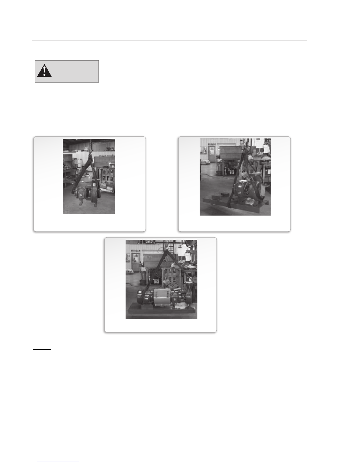
Care should be taken when unloading and handling the pump, especially with regards to rigging
and lifting. Suggested methods are:
FIGURE 1
PUMP ONLY
FIGURE 3
PUMP WITH BASE & MOTOR
FIGURE 2
PUMP WITH BASE ONLY
Never use eyebolts for lifting the pump. Eyebolts are used only to assist in lifting the back pullout assembly component of the pump during maintenance.
Upon receipt, a thorough inspection should be made of the pump and related equipment. If
materials are not received in good condition or there are shortages, make a notation of the
damage and/or shortage on both the receipt and the freight bill. Submit any claims to the
transportation company promptly! A documentation package is included with the pump
shipment. Do not discard these materials. Put them in a safe place for easy reference.
GRISWOLD PUMP COMPANY Introduction Page 4
Installation, Operation and Maintenance Manual
Griswold Model 811
Storage
If pumps are to be stored prior to installation, they should be kept in a clean, dry environment.
Depending upon the duration of the storage, it may be necessary to apply preservatives and to
perform routine maintenance such as regularly rotating shafts to prevent flat spots from forming
on the bearings in both the pump and driver. If pumps are to be stored for more than 4-6 months
prior to installation and/or start-up, follow recommendations listed below.
Storage for more than 4-6 months will require pumps to be prepared for long-term storage.
Preservative treatment should be added to the power frame to aid against condensation and rust.
Treatment shall be similar to Royal Purple VP Preservative Oil #10. All machine surfaces that
are not painted or not of corrosion resistant material shall be coated with a light coat of machine
oil or grease. The pump and motor shaft should be turned several rotations every 3 months or
less and left 90 degrees from the original position. Store in a dry protected location insuring that
flange covers are left in place and all openings are plugged.
Similarly, if the pump is to be installed and then started at a later date, it may be advisable to
protect the pump during the idle time, especially if it’s to be exposed to the elements.
Safety
WARNING
If procedures outlined in this manual are not followed, personal injuries may result.
Griswold pumps have been designed and manufactured for safe and reliable operation when
properly applied, operated and maintained in accordance with this instructional manual. Your
safety is a primary concern for Griswold Pump, so we offer the following recommendations:
General Safety Precautions
Never apply heat to remove an impeller.
Trapped liquid, when heated, may cause an
explosion.
Never use heat during the dis-assembly of the
pump. Trapped liquid, when heated, may cause
an explosion.
Never operate the pump without the coupling
guard in place.
Never operate the pump beyond the service
conditions for which it was sold.
Always start the pump only with proper prime.
Never run the pump dry.
Never operate the pump without the suction
valve fully open.
Always wear personal protective gear – safety
glasses, steel-toed shoes, gloves, etc., when
working on the pump.
Always lock out the driver before performing
maintenance on the pump.
Never operate the pump with safety devices
disengaged.
Always follow established decontamination
procedures before working on the pump.
Never operate the pump with a fully-closed
discharge valve. If the pump is operated with
no flow, its temperature will increase and
damage may result.
GRISWOLD PUMP COMPANY Introduction Page 5
Installation, Operation and Maintenance Manual
Griswold Model 811
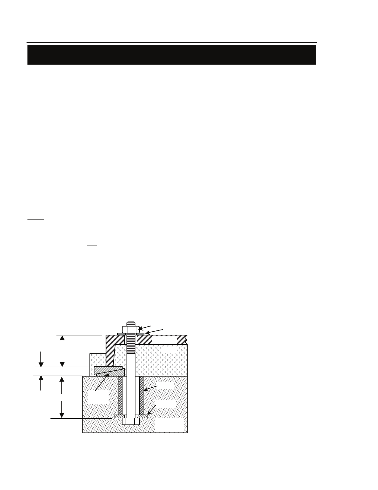
Figure 4
Typical Anchor Bolt (Sleeve Type)
Concrete
Foundation
Anchor Bolt
Per Pump
0.75"
–
Leve
ling
Anchor bolts are usually sized
? " smaller
than the anchor bolt hole size in the base.
sizes larger than the anchor bolt.
Allow approx. ¾"
foundation for grouting.
here. Alternatively, a “hook” or “J” type
grout from entering this area.
Note:
INSTALLATION
Installation
The pump location should be clean, well ventilated, properly drained and allow room for
maintenance and inspection.
Trouble-free operation of a pump begins with proper installation with particular attention being
paid to the baseplate and piping attachments. A secure baseplate will enable accurate alignment
to be attained and maintained. Flange loads from misaligned or improperly supported piping
will make alignment difficult and will cause premature failures.
Baseplates and Anchors
The preferred mounting for a baseplate is on a concrete pad with grouting. No matter how robust
its design, there is always some flexibility in the baseplate itself. If there is insufficient support
under the baseplate, it can distort causing alignment difficulties and normal vibrations can be
amplified to unacceptable levels through resonances in the pump support and/or piping. A
properly grouted baseplate will resist distortion and will provide sufficient mass to dampen any
vibration.
When pumps and motors are assembled on a baseplate at the factory, a preliminary
alignment is done to ensure that the pump and motor can be aligned at its installation.
This alignment is not to be considered as a final alignment. The factory alignment can,
and does, change during shipment and when the pumping unit is installed. Actually,
several alignments are necessary as will be described later.
Anchor (foundation) bolts are used to hold the baseplate to its support structure, whatever that
may be. In the preferred case of mounting the pump unit on a concrete pad, the anchor bolts are
set into the pad as indicated in the following illustration. When pouring the pad, it’s helpful to
have a wooden template attached to the foundation form to position the anchor bolts at their
locations as indicated on the pump unit assembly drawing.
Nut
Washer
Calculate bolt length as indicated in
Figure 4 at the left.
The ID of the sleeve should be two bolt
- 1½" space between
the bottom edge of the baseplate and the
A “Sleeve” type anchor bolt is shown
Drawing
12" - 18"
Wedges
Baseplate
Grout
Sleeve
Washer
GRISWOLD PUMP COMPANY Installation Page 6
anchor bolt may be used.
Pack the space between the anchor bolt
and sleeve to prevent concrete and/or

Installation, Operation and Maintenance Manual
Griswold Model 811
Note:
Note
:
done in two steps as long as the first step is allowed to cure completely before the second
step is applied
Installing and Grouting Base
Before the baseplate is installed, it is advisable to thoroughly clean
the underside to enable the grouting to adhere to it. Do not use oil-based cleaners since
Once the concrete pad has cured, the baseplate can be carefully lowered over the anchor bolts.
Place shims or tapered wedges under the baseplate at each of the anchor bolt positions to provide
about 0.75" – 1.50" clearance between the base and the foundation. Adjust shims/wedges to level
the baseplate. Since there may be some flexibility in the baseplate, we must perform an
initial alignment prior to grouting to ensure that a final alignment can be achieved. See
section covering Alignment of Pump/Driver Shafts. Potential problems here include bowing
and/or twisting of the baseplate. If gross misalignment is observed, shims/wedges may have to
be added under the mid-point of the base or the shims/wedges at the corners may have to be
adjusted to eliminate any twist. If the driver feet are bolt-bound for horizontal alignment, it may
be necessary to loosen the pump hold-down bolts and shift the pump and driver to attain
horizontal alignment. When alignment has been achieved, lightly tighten the anchor bolts. The
anchor bolts should not be fully tightened until the grout has set.
grout will not bond to it.
Grouting furnishes support for the pump unit baseplate providing rigidity, helping to dampen any
vibration and serves to distribute the weight of the pump unit over the foundation. To be
effective, grouting must completely fill all voids under the baseplate. For proper adhesion or
bonding, all areas of the baseplate that will be in contact with the grout should be thoroughly
cleaned. See note above. The grout must be non-shrinking. Follow the directions of the grout
manufacturer for mixing. Proceed with grouting as follows:
If the size of the equipment or the layout of the installation require it, grouting can be
1. Build a sturdy form on the foundation around the baseplate to contain the grout.
2. Soak the top of the concrete foundation pad thoroughly. Remove surface water before
pouring.
3. Pour the grout through the hole(s) in the top and/or through the open ends of the channel
steel baseplate, eliminating air bubbles by tapping, using a vibrator or pumping the grout into
place. If necessary, drill vent holes into the top of the base to evacuate air.
4. Allow grout to set completely, usually a minimum of 48 hours.
5. Tighten foundation anchor bolts.
6. Re-check alignment to ensure that there have been no changes.
7. After the grout has dried thoroughly, apply an oil base paint to shield the grout from air and
moisture.
You may then proceed to connect suction and discharge piping
GRISWOLD PUMP COMPANY Installation Page 7

Installation, Operation and Maintenance Manual
Griswold Model 811
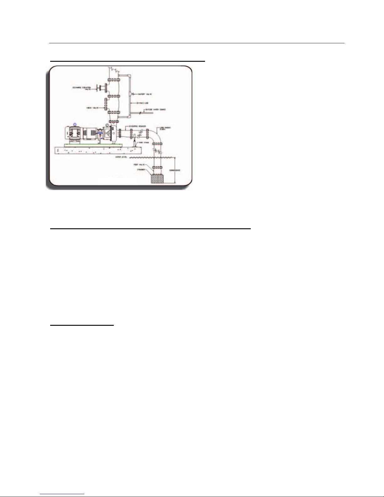
Suction and Discharge Piping
A complete instruction for piping design is beyond the scope of this manual. A comprehensive
guideline is available in the Hydraulic Institute Standards from The Hydraulic Institute,
9 Sylvan Way, Parsippany, NJ 07054, www.pumps.org. Note the following highlights:
In general, all piping must be supported independently of, and line up naturally with, the pump
flanges. Even a small amount of pipe strain, or flange loading, will cause misalignment of the
pump and motor shafts and cause vibration and premature wear. In cases of pumping at
elevated temperatures, pipe expansion must be accommodated with expansion loops or
expansion joints. These must be properly anchored to prevent pipe strain from being imposed on
the pump from both thermal expansion and hydraulic reactive loads.
With the initial installation of the pump system, all piping must be thoroughly cleaned and/or
flushed prior to pump start-up. Weld slag, rags, dirt and other debris can and will cause damage
to the pump.
Piping design should incorporate the ability to flush prior to the removal of pump components in
services where corrosive or otherwise harmful liquids are handled.
It is important to monitor the performance of a pump. So, in this regard, it’s recommended that
gauges be installed in the suction and discharge lines. Select the appropriate gauge range to
provide accurate readings. On pumps with suction lift, use a compound or vacuum gauge on the
suction side.
Suction Piping - General
Properly designed and installed suction piping is critical to the successful operation of a pump.
When pump operational problems are encountered, the causes are most often on the suction side.
To achieve proper pump performance, consider the following:
1. Avoid using elbows close to the pump suction flange as this can create an uneven flow into
the pump suction and impeller. If an elbow is necessary, it should be of the long radius type
and there should be a minimum of six pipe diameters of straight pipe between the elbow and
the pump suction nozzle.
2. The suction pipe should be at least one size larger than the pump suction size. This will
require an eccentric reducer to transition from the suction pipe to the pump suction flange.
The flat side of the eccentric reducer is at the top. This is to prevent air pockets in the suction
line.
3. If a strainer is used on the pump suction side, it must have a free area at least three (3) times
the area of the suction pipe. It must be checked and cleaned regularly as a clogged strainer
will reduce NPSH available and may cause cavitation.
4. Never throttle the suction side of the pump. This can cause cavitation and will likely damage
the pump.
5. When the suction supply source feeds more than one pump, separate suction lines are
recommended.
GRISWOLD PUMP COMPANY Installation Page 8
Installation, Operation and Maintenance Manual
Griswold Model 811
Suction Piping – Suction Lift Installations
FIGURE 5
Suction Piping – with Positive Head (Flooded Suction)
1. The suction line must include an isolation valve to close off the source of supply when
performing inspection or maintenance on the pump. Install this valve at least two pipe
diameters before the pump suction nozzle.
2. Piping should be level or gradually slope downward from the suction source in order to
avoid air pockets.
3. Attention should be paid to the design of the exit from the supply source to prevent the
formation of vortices or eddies that can draw air into the pump. This relates to the
velocity of the outflow and the submergence of the supply exit below the liquid level.
1. Suction lines when operating under lift
conditions must be absolutely free from
air leaks.
2. Suction piping should gradually slope
upward toward the pump.
3. NPSH available must be greater than the
NPSH required by the pump.
4. A means of priming the pump, such as a
foot valve, must be provided.
5. Pipe must be supported properly to
prevent flange loading.
6. Provide adequate submergence over the
suction pipe inlet to prevent formation
of vortices.
Discharge Piping
1. Discharge piping will normally be larger than the pump discharge size, so a concentric
increaser is usually used for adaptation. Locate increaser below check valve.
2. A check valve and isolation valve should be located in the discharge line. The check
valve should be located between the isolation valve and the pump. This will prevent back
flow through the pump (reverse rotation) and will also serve to reduce any back pressure.
3. If an expansion joint is used, it should be located between the check valve and the pump.
Proper anchoring is necessary.
GRISWOLD PUMP COMPANY Installation Page 9
Installation, Operation and Maintenance Manual
Griswold Model 811
Driver power must be locked out b
efore beginning any alignment procedure. Failure to lock
Note:
Note:
Alignment of Pump/Driver Shafts
WARNING
out driver power may result in serious physical injury.
Proper alignment is the responsibility of the installer and user of the equipment.
Check alignment if process temperature changes, piping changes and/or pump service is
Pump and driver shafts need to be aligned for both parallel and angular alignment. If there is a
misalignment of the shafts, it will place a mechanical load on the pump and driver shaft/bearing
assemblies as well as the coupling. This will result in vibration, noise and premature failures.
performed.
PARALLEL MISALIGNMENT
FIGURE 6
ANGULAR MISALIGNMENT
FIGURE 7
To bring shafts into alignment, we first need to determine the amount and direction of both
parallel and angular misalignments. We can then shim and reposition to correct.
It’s preferable to shim ONLY under the driver feet since good contact between the pump feet and
the base is necessary to resist any pump flange loading that might be imposed by the suction
and/or discharge piping.
There are three methods commonly used to determine misalignment:
1. Straight edge and calipers or inside micrometer (least accurate)
2. Dial indicator (reasonably accurate)
3. Laser Alignment Equipment. See manufacturer’s instructions for use.
GRISWOLD PUMP COMPANY Installation Page 10

Installation, Operation and Maintenance Manual
Griswold Model 811
Note:
In any case, disregard the coupling manufacturer’s published misalignment limits, as these
Note:
Since any misalignment will impose loads on the pump and driver shafts, the objective is to
minimize any misalignment in order to protect the pump and driver and minimize any tendency
for vibration. Suggested misalignment limits are:
Pump Frame Group Max. Parallel Max. Angular
S, M, L 0.005" 0.005"
XL 0.010" 0.010"
For optimum performance and Mean Time Between Pump Maintenance (MTBPM), use
alignment limits half of those shown above.
will impose unacceptable loads on the pump and motor shafts and bearings.
Alignment must be done at several different times:
1. Prior to grouting baseplate during installation
2. After grouting baseplate and tightening anchor bolts
3. After attaching suction and discharge piping prior to initial operation
4. Hot alignment after equipment temperatures have stabilized
5. After pump maintenance if back pull-out assemblies are removed
Table 1
Since the Model 811 pump is foot-mounted, its shaft centerline will rise when handling pumpage
at elevated temperatures. Similarly, the motor shaft centerline will rise as it reaches its operating
temperature. Therefore, we will often purposely mis-align shafts vertically during cold
alignment to allow for thermal growth, thus bringing the shafts into alignment at operating
temperature. This is shown in Table 2 on Page 15.
The Griswold Model 811 is an ANSI B73.1 Process Pump and is, therefore, furnished with a
spacer coupling to enable removal of the back pull-out assembly without disturbing the casing or
moving the motor driver.
Alignment is done with the coupling spacer removed.
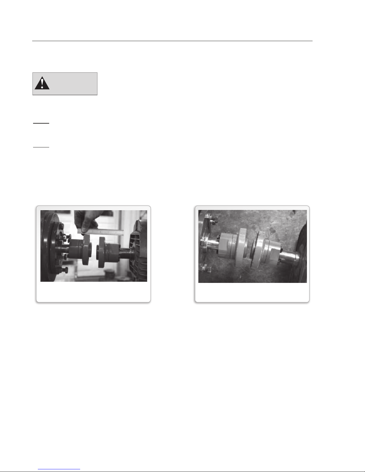
The most simple alignment check is with a straight edge and calipers or inside micrometer. This
method is the least accurate, but it will serve if a dial indicator or laser is not available.
GRISWOLD PUMP COMPANY Installation Page 11
Installation, Operation and Maintenance Manual
Griswold Model 811
With coupling hubs stationary, use inside micrometer
or calipers to measure the gap between the coupling
intervals. Adjust and/or shim equipment
With coupling hubs stationary, lay straight edge flat
rim of coupling hub to determine vertical and
equipment until the straight edge lies flat against both
1.
Scribe or mark index lines on both
indicator reading (TIR) for a complete
turn does not exceed the values shown
Alignment with Straight Edge and Micrometer
hubs at 90
0
until the gap difference at all points around the
hub(s) is less than the value shown in Table 1 page
13.
FIGURE 8
ANGULAR ALIGNMENT
against
horizontal alignment offsets. Adjust and/or shim
hub rims, vertical and horizontal.
FIGURE 9
PARALLEL ALIGNMENT
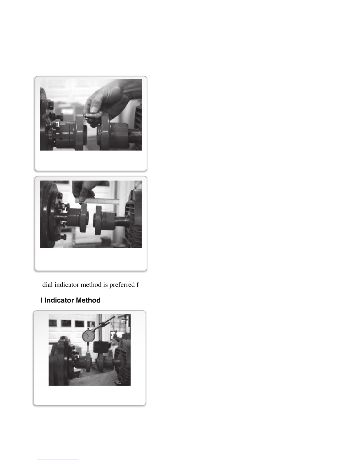
The dial indicator method is preferred for checking alignment
Dial Indicator Method
FIGURE 10
DIAL INICATOR SETUP
GRISWOLD PUMP COMPANY Installation Page 12
coupling hubs to indicate where the
dial indicator point rests.
2. Set dial indicator to zero.
3. Slowly turn BOTH coupling hubs so
that the index lines match or the
indicator point is always on the mark.
4. Observe dial reading to determine
required adjustments.
5. Acceptable parallel and angular
alignment occurs when the total
in Table 1 page 13.

Installation, Operation and Maintenance Manual
Griswold Model 811
intended operating temperature. When the shafts are aligned “cold” (at ambient temperature),
we will intentionally position the motor shaft up or down in vertical parallel alignment to allow
for thermal growth. Then, when the alignment is checked “hot” (at stable operating
temperature), the shafts should be confirmed to be in alignment. Use the values in the following
table:
Table 2
Cold Setting of Parallel Vertical Alignment
As previously mentioned, pump and motor shafts need to be in alignment while they are at their
Pumpage
Set DRIVER Shaft,
Temperature
500 F 0.002" low
1500 F 0.001" high
2500 F 0.005" high
3500 F 0.009" high
4500 F 0.013" high
5500 F 0.017" high
6500 F 0.021" high
7000 F 0.023" high
inches
Laser alignment is usually the most accurate method. Follow the laser alignment equipment
manufacturer’s instructions for this method.
GRISWOLD PUMP COMPANY Installation Page 13
Installation, Operation and Maintenance Manual
Griswold Model 811
Operators must become familiar with the installation and service manual as supplied by the
FINNED TUBE COOLER
Drivers
Electric Motors
Connect power supply in conformance with local and national codes. Line voltage and wire
capacity must match the ratings stamped on the motor nameplate.
CAUTION
Severe damage can be done to the pump if it is driven in reverse rotation.
During installation, when the motor is jogged to check rotation,
this MUST be done with the coupling spacer removed.
Do not install coupling spacer until correct motor rotation has been established
Engine-Drives
WARNING
engine manufacturer.
Safe and efficient operation of a pumping unit driven by an engine, whether diesel or gasoline
requires the installation to satisfy the following requirements:
1. Be well ventilated in order to keep the ambient temperature as low as possible.
2. Provide ample air for proper combustion.
3. Provide the engine with an efficient exhaust system so that the combustion gases
discharge with a minimum of backpressure.
4. Provide for a fuel system of adequate capacity, which meets the local codes.
5. Provide ample accessibility to service engine.
6. Provide engines / drives for correct rotation of the pump. Engine rotation is determined at
the factory. No change of engine rotation can be made in the field.
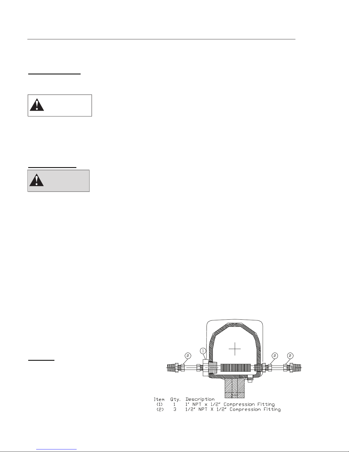
Flushing and Cooling Lines
Pump auxiliaries such as flushing and
cooling are application-specific. In
general, however, note the following:
Cooling
Bearing cooling is required for applications
with pumpage temperature above 3500 F or
if bearings operate above approx. 1800 F.
Bearing cooling is accomplished with a
finned-tube cooler,
GRISWOLD PUMP COMPANY Installation Page 14

Installation, Operation and Maintenance Manual
Griswold Model 811
which is inserted into the oil sump in the bearing frame.
In some instances, mechanical seals are flushed from the pump discharge through a heat
exchanger. Cooling water is to be supplied to the “water” side of the heat exchanger.
Flushing
Flushing is usually associated with the shaft sealing and is application specific.
Mechanical seals are usually flushed to prevent localized heating at the seal faces. Flush may be
with a bypass line from the pump discharge to the gland flush connection or from the gland flush
connection to the pump suction. If the pumpage contains solids or other contaminants the seal
may be flushed from an external clear liquid source, usually into the seal gland flush connection.
If packing is used and flushing is required, such as when the pumpage contains minor amounts of
solids, which would wear the packing and sleeve, a clean water flush is introduced into the
lantern ring connection on the stuffing box cover. This injects water into the lantern ring area
between the rings of packing to prevent the intrusion of solids. It’s helpful to have a pressure
gauge, needle control valve and flow indication device in this flush line to monitor flushing
liquid.
If the pump is in a suction lift application, the stuffing box pressure may be less than atmospheric
pressure in which case pressurized water should be supplied to the lantern ring connection to
effect a water seal. If the pumpage is clean, this may be a bypass line from the discharge of the
pump. If the pumpage contains solids, external water injection may be necessary as noted above.
Prior to pump start-up, all cooling and flushing lines (as applicable) must be installed and
functional.
GRISWOLD PUMP COMPANY Installation Page 15
 Loading...