

Page 1
1
OPERATOR’SMANUAL
AND PARTS LIST
MODEL GRTSN150a STAPLER
MODEL GRTSN100 STAPLER
Page 2
32IMPORTANT SAFETY INFORMATION
Youmust readthisentiremanualandfamiliarizeyourselfwithall
safety,operating, andserviceinstructionsbefore loading,handling,
orusingyour tool. Whenusedcorrectly, pneumatic fastening
toolsprovide a lightweight,powerful,and safemeansof fastening.
Usedimproperly,these tools can cause serious injury to youand
thosearoundyou.
TABLE OF CONTENTS
TABLE OF CONTENTS
-------------------------------
3
GRTSN100 SPECIFICATIONS
----------------------
4
GRTSN100 Fastener Selection Chart
--------
4
GRTSN150a SPECIFICATIONS
---------------------
5
GRTSN150a Fastener Selection Chart
------5SAFETY
----------------------------------------------------
6
TOOL PARTS
------------------------------------------
10
PART DESCRIPTIONS
------------------------------
11
GRTSN150a OPERATION
--------------------------
12
Loading Staples
----------------------------------
12
Adjusting Staple Drive
--------------------------
13
Clearing Staple Jams
---------------------------
13
GRTSN100 OPERATION
----------------------------
14
Loading Staples
----------------------------------
14
Adjusting Staple Drive
--------------------------
15
Clearing Staple Jams
---------------------------
15
TOOL OPERATION
-----------------------------------
16
MAINTENANCE
---------------------------------------
17
Lubrication
-----------------------------------------
17
Cleaning
--------------------------------------------
17
Trigger Check
-------------------------------------
17
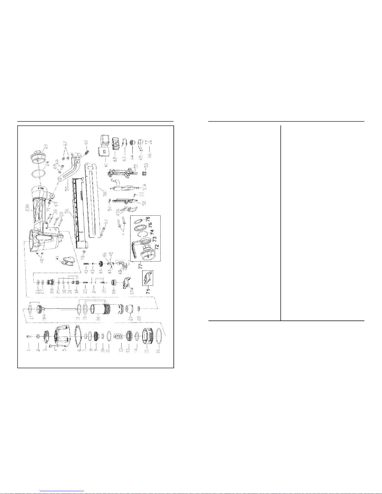
GRTSN150a PARTS SCHEMATIC
---------------
18
GRTSN150a PARTS LIST
--------------------------
19
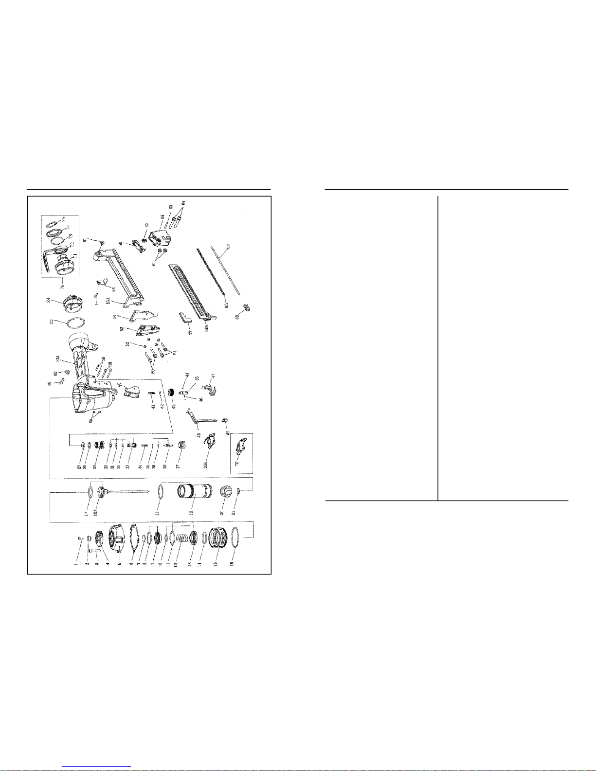
GRTSN100 PARTS SCHEMATIC
-----------------
20
GRTSN100 PARTS LIST
----------------------------
21
TROUBLESHOOTING
-------------------------------
22
TOOL CHECKS
----------------------------------------
23
WARRANTY
--------------------------------------------
24
NOTES
---------------------------------------------------
26
Page 3

5
4
GRTSN150a SPECIFICATIONS
GRTSN150a SPECIFICATIONS
MODEL
GRTSN150a
FASTENERRANGE
3/4” - 1 1/2 ” (19 mm - 38 mm)
FASTENERTYPE
18 Ga. Staples
CROWNSIZE
1/4” (6.4 mm) Narrow Crown
MAGAZINE CAPACITY
140STAPLES
MAX AIR PRESSURE
110 psi (7.6 bar)
MINAIR PRESSURE
70 psi (4.8 bar)
TOOL WEIGHT
2.8 lbs. (1.3 kg)
TOOL LENGTH
11.25” (28 cm)
TOOLHEIGHT
10.15” (26 cm)
TOOL WIDTH
2.25” (5.7 cm)
STANDARDTRIGGER
Sequential
ACCESSORYTRIGGER
Dual Action (Bump/Trigger Fire)
AIR INLET
1/4NPT
AIRCONNECTION
Male Quick Connect Coupler
LUBRICATION
10W Air Tool Oil (Provided)
NOISE CHARACTERISTIC VALUES IN ACCORDANCE WITH ISO 3774,ISO 11201:
A-weighted single-event sound
pressure level at operator’s position
----------------------------------
LpA, 1s = 89 dBA
A-weighted single-event sound power level
-----------------------
LwA, 1s = 100 dBA
A-weighted single-event surface sound
pressure level
----------------------------------------------------------------
LpA, 1s = 87 dBA
VIBRATION CHARACTERISTIC VALUES IN ACCORDANCE WITH ISO 8862-1
Weighted root mean square acceleration
----------------------------
= 1.9 m/s
2
For best results, use Grip-Rite™ collated fasteners.
LEG
BOX
CROWN
WIRE
GALVANIZED
LENGTH
QTY.
SIZE
GA.
STEELSKU
3/4” (19 mm)
5M
1/418GRL11
7/8” (22 mm)
5M
1/418GRL12
1” (25 mm)
5M
1/418GRL13
1-1/8” (29 mm)
5M
1/418GRL14
1-1/4” (32 mm)
5M
1/418GRL15
1-1/2” (38 mm)
5M
1/418GRL17
FASTENER SELECTION CHART
GRTSN100 SPECIFICATIONS
GRTSN100 SPECIFICATIONS
MODEL
GRTSN100
FASTENERRANGE
1/2” - 1 ” (13 mm - 25 mm)
FASTENERTYPE
18 Ga. Staples
CROWNSIZE
1/4” (6.4 mm) Narrow Crown
MAGAZINE CAPACITY
110 STAPLES
MAX AIR PRESSURE
110 psi (7.6 bar)
MINAIR PRESSURE
70 psi (4.8 bar)
TOOL WEIGHT
2.7 lbs. (1.2 kg)
TOOL LENGTH
9.75” (24.8 cm)
TOOLHEIGHT
8.6” (21.8 cm)
TOOL WIDTH
2.25” (5.7 cm)
STANDARDTRIGGER
Sequential
ACCESSORYTRIGGER
Dual Action (Bump/Trigger Fire)
AIR INLET
1/4NPT
AIRCONNECTION
Male Quick Connect Coupler
LUBRICATION
10W Air Tool Oil (Provided)
NOISE CHARACTERISTIC VALUES IN ACCORDANCE WITH ISO 3774,ISO 11201:
A-weighted single-event sound
pressure level at operator’s position
----------------------------------
LpA, 1s = 89 dBA
A-weighted single-event sound power level
-----------------------
LwA, 1s = 100 dBA
A-weighted single-event surface sound
pressure level
----------------------------------------------------------------
LpA, 1s = 87 dBA
VIBRATION CHARACTERISTIC VALUES IN ACCORDANCE WITH ISO 8862-1
Weighted root mean square acceleration
----------------------------
= 1.9 m/s
2
For best results, use Grip-Rite™ collated fasteners.
LEG
BOX
CROWN
WIRE
GALVANIZED
LENGTH
QTY.
SIZE
GA.
STEELSKU
1/2” (13 mm)
5M
1/418GRL08
5/8” (16 mm)
5M
1/418GRL10
3/4” (19 mm)
5M
1/418GRL11
7/8” (22 mm)
5M
1/418GRL12
1” (25 mm)
5M
1/418GRL13
FASTENER SELECTION CHART
Page 4
7
6
SAFETY
SAFETY
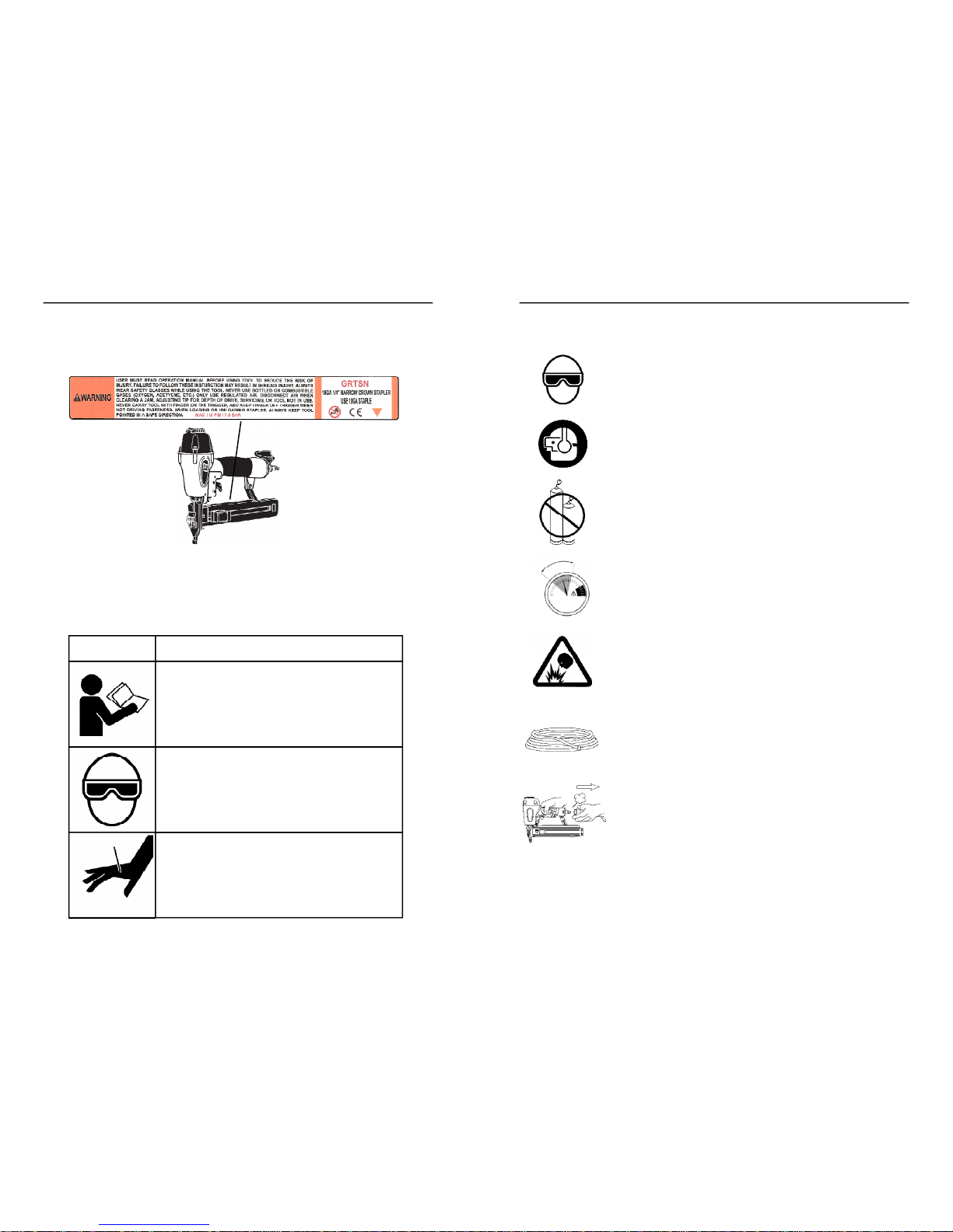
SAFETY LABELS
This pneumatic fastening tool includes a warning label to help remind you of
important safety information when operating the tool. The safety label must be
legible at all times, and must be replaced if it becomes worn or damaged.
SYMBOL
DESCRIPTION
READTHE MANUAL
-Themanualcontains
importantsafetyand operatinginstructions
that must befollowed. All tool users must
readthe manualbefore usingthetool.
WEARSAFETYGLASSES
-Tooloperator
and bystandersmust wear safety glasses
withsideshield thatmeetANSI Z87.1
requirements.
RISKOF PERSONALINJURY
-Failureto
followall safety and operatinginstructions,
or misuse of the tool, can result inserious
injuryto tool operator and bystanders.
WEARSAFETYGLASSES
Always wear safety glasses with side shields that meet ANSI
Z87.1 requirements when operating the tool. Make sure all
others in work area wear safety glasses.
WEARHEARINGPROTECTION
Wear hearing protection to protect your hearing from noise.
Prolonged exposure to loud noise can result in hearing loss.
NEVEROPERATETHETOOLWITHOXYGENOR OTHER
BOTTLEDGASES
Oxygen and other reactive or high-pressure bottled gases
can cause the tool to explode. Use clean, dry regulated
compressed air from a properly operating air compressor.
DONOTEXCEEDMAXIMUMRECOMMENDEDOPERATINGAIR
PRESSURE OF110 PSI/7.6 Bar.
Exceeding the maximum recommended air pressure can
cause the tool housing to burst, or cause premature failure of
components.
NEVERCONNECTTHE TOOLTO AN AIRSUPPLYTHATHAS
THEPOTENTIALTO EXCEED180 PSI/12.4Bar.
Using a regulated air supply with a line or tank pressure
greater than 180 psi can cause the tool to burst if the air line
regulator fails suddenly.
USEAN AIRHOSE RATED FOR 180 PSI/12.4Bar OR
GREATER
Always use air hose rated to handle 180 psi or the maximum
potential pressure of the air supply.
ONLYUSEARELIEVING-TYPEAIRCOUPLINGINTHE TOOL
AIRINLETOPENING.
Use of a non-relieving air coupling on the tool can trap air
inside the tool housing, and allow the tool to drive a fastener
even after the air hose has been disconnected.
SAFETY INSTRUCTIONS
110psi
4.8bar
70psi
7.6bar
SAFETY SYMBOLS
These safety symbols provide a visual reminder of basic safety
rules, and the personal injury hazard that may arise if all safety and
operating instructions are not followed. Make sure you understand
the meaning of each of these symbols, and protect yourself and
others by obeying all safety and operating instructions.
Page 5
9
8
SAFETY
SAFETY
DONOTATTEMPTTO OPERATETHETOOLIFTHE TOOL’S
OPERATINGCONTROLSHAVEBEENMODIFIEDORARENOT
WORKINGPROPERLY.
Attempting to use a tool with modified or malfunctioning
trigger or workpiece contact can result in a fastener being
driven unintentionally.
USECORRECTFASTENERS
Only use the correct fastener for the tool. Using fasteners
with incorrect specifications can jam the tool or cause
serious injuries.
USETHECORRECTFASTENERSFORTHEAPPLICATION.
Using the wrong fasteners can cause the workpiece to split
and allow the fastener to fly free.
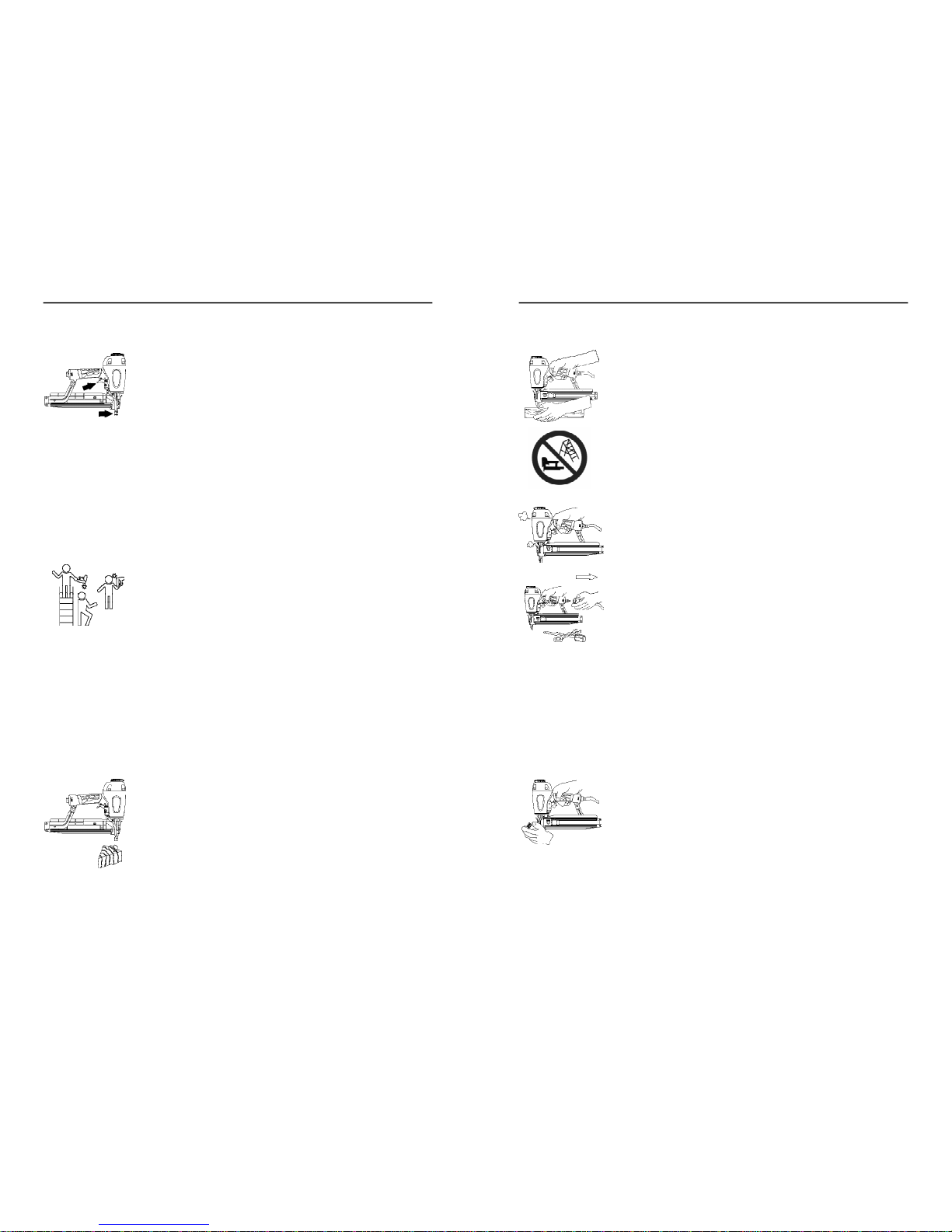
KEEPTOOL POINTEDINA SAFEDIRECTIONWHENLOADING
FASTENERS.
Never point the tool at yourself or anyone else when loading
fasteners.
DONOTLOAD TOOLWITHTRIGGERORWORKPIECE
CONTACTDEPRESSED.
Depressing the trigger or workpiece contact during loading
can result in an unintentional fastener drive if both devices
are accidentally actuated at the same time.
KEEPFINGEROFFTRIGGERUNTILTOOLIS INPOSITIONTO
DRIVEAFASTENER.
An unexpected bump or sudden contact with your body or that
of a bystander can result in serious injuries.
AVOIDDRIVINGFASTENERSINTOKNOTS,ONTOPOF
OTHERFASTENERS,ATWORKPIECEEDGES,ORINTO
BRITTLEMATERIALS.
Driving fasteners into extremely hard materials, or driving into
workpiece edges, can cause fasteners to deflect away from
the workpiece. Flying fasteners can cause serious injuries.
SAFETY INSTRUCTIONS
KEEPHANDSANDBODYPARTSAWAYFROMAREABEING
FASTENED.
Fasteners can deflect and turn as they are being driven into
the workpiece, and penetrate fingers, hands, and other body
parts that may be in the fastening area.
DONOTOVERREACHORWORKWHILEON UNSTABLE
FOOTING
If you lose your balance while fastening, you could drive a
fastener into yourself or a bystander.
DONOTUSETOOLIFTOOL MALFUNCTIONSORBEGINS
LEAKINGAIR.
Operating a malfunctioning tool can result in an unexpected
fastener discharge and injury to yourself or others.
DISCONNECTTHETOOLFROMTHEAIRSUPPLYTORE-
LOAD,CLEARJAMS,ORPERFORMMAINTENANCE.
Never attempt to reload a tool, clear a jam, or perform
maintenance without first disconnecting the air supply.
NEVERLEAVEALOADED,PRESSURIZEDTOOL
UNATTENDED
A loaded, pressurized tool could be picked up or handled by
someone who is unfamiliar with the tool or that has not read
the tool manual.
KEEPTOOLSOUTOFTHEREACHOFCHILDREN
Place the tool back in the tool box after use, and store the tool
out of reach.
DONOTMODIFYTOOL
Modifications can cause a tool to be unsafe and can cause
the tool to operate improperly.
SAFETY INSTRUCTIONS
Page 6
11
10
DESCRIPTION
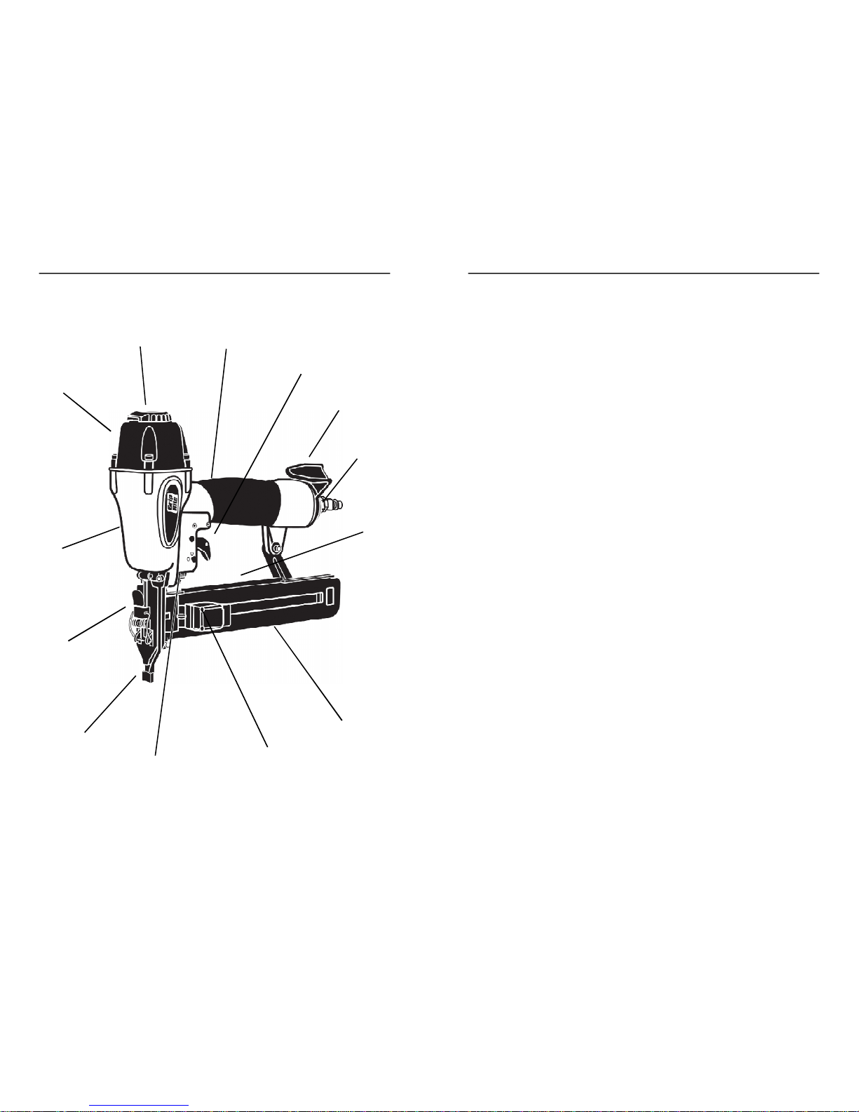
PART DESCRIPTIONS
1.
360°AdjustableAir Deflector
-Tool-freeadjustmentblowsexhaust
air awayfrom operator. 12locking positionsfor secure settings.
2.
CushionedGrip
-Cushionedhandgripreducesfatigueandprovides
comfortableoperation.
3.
Sequential Trigger
(Standard) -
Actuates tool only when correct
triggeroperatingsequenceis followed. Doesnot allowbump firing.
DualAction Trigger (Accessory)
-Actuatestool whenworkpiece
contact is depressedagainst work surface. Permits contact-trip
(bumpfire)or trigger-fireoperation.
4.
Rotating Belt Hook
- Durable tool hookslidesonbelt. Holds tool
securelyand keepsit in reach for greaterproductivity.
5.
AirCoupling
- Quick-disconnectmale couplingallowsquickconnec-
tion to air hose. Dust cap keeps dirt out when tool is not in use.
6.
SafetyWarning Label
- Provides important safety remindersthat
mustbe followedwheneverhandling,operating,orservicingthetool.
7.
Top Load Staple Magazine (GRTSN150a)
- Holds fasteners
securely, and allowsquick check of staple size and quantity.
Bottom Load Staple Magazine (GRTSN100)
- Holdsfasteners
securely,and featuresreload indicatorwindow.
8.
Spring-loadedPusher -
Providespositive fastener feedinginall tool
positions. Latchesin loadingpositionfor rapid, one-handedloading.
Triangleindicatorsshowwhenit’stime toreload.
9.
AdjustableDepth of Drive
- Easy, tool-free depth of drive dial allows
adjustmentstobe made forconsistentdepth control.
10.
WorkpieceContact
-Spring-loadedcontact mechanismprevents
toolfrom drivinga fastenerunlesstoolispresseddownand held
againsta work surface.
11.
E-Z ClearLatch (GRTSN150a)
-Clearjammedfastenersfrom nose
withouttools.
12.
ToolHousing
-Diecastaluminumhousingforjobsitedurability.
13.Cap
- Seals tool housing.
MetricHex Wrenches
- Included with tool toallow tightening of
metric screwsand depth of drive adjustments. Keep tools in tool
casefor periodictightening of screws.
AirTool Oil
-Lightweightoil formulatedforusein airtools provides
properlubrication to o-ringsand internal parts.
SafetyGoggles
-Providerequired eyeprotection
DESCRIPTION
TOOL PARTS
12313697121110854
Page 7
13
12
GRTSN150a OPERATION
GRTSN150a OPERATION
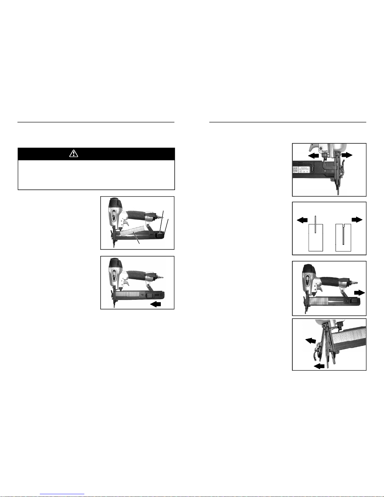
LOADING FASTENERS
GRTSN150aLOADINGINSTRUCTIONS
Afastenercan be driven unintentionallyif the trigger andsafetybracket
areactivated atthe same time. Alwaysdisconnect tool from air supply
beforeloadingfasteners,making adjustments, orperformingany service
ontool. Keep finger off trigger until readytodrive a fastener.
DANGER
1.
Pull pusher (A) backto latched
positionat rear of magazine.
2.
Loadstaple strips(B) over
magazine track. Slide strips
downso that staple crowns
ride on top rail, then slide
forwardtowardtoolnose.
3.
Pull pusher (A) backand press
releaselever(C)to release
latch. Slidepusherforward
againststaple strips and
release. DO NOT allowpusher
tosnapforwardagainst
staples.
4.
Toolisnowloadedand ready
to be connectedto an air
supply for operation.
ADJUSTING STAPLE DRIVE
1.
Disconnecttool fromair supply
usingquick-connectcoupling.
2.
Turnadjustmentdialforwardto
decreasestapledrive, or
backwardto increase staple
drive, as shown by symbols on
tool.3.Connecttool to air supply, and
drive staplestocheckfor
correct depthof drive.
4.
Makedepthof driveadjust-
mentsasneededto maintain
consistentstapledriving.
CLEARING STAPLE JAMS
1.
Disconnecttool fromair supply
usingquick-connectcoupling.
2.
Pull pusher back to latched
positionat rear of magazine.
3.
OpenE-Z Clear latch andopen
door.4.Removejammedfastener.
5.
Closedoor andsecurewith
latch.6.Releasepusherand slide
forwardagainst staple strips.
7.
Connectair supply and check
toolfor normal operation.
ACB
STAPLETOO HIGH
TURN DIAL
BACKWARD
STAPLETOO
DEEP TURN
DIAL
FORWARD
DRIVE
DEEPER
DRIVE
LESS
DEEP
Page 8
15
14
GRTSN100 OPERATION
GRTSN100 OPERATION
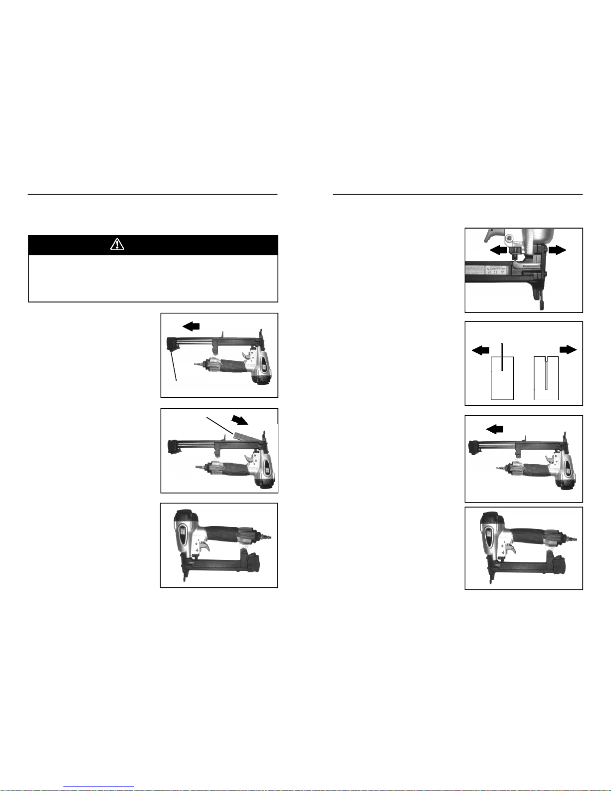
LOADING FASTENERS
GRTSN100LOADINGINSTRUCTIONS
Afastenercan be driven unintentionallyif the trigger andsafetybracket
areactivated atthe same time. Alwaysdisconnect tool from air supply
beforeloadingfasteners,making adjustments, orperformingany service
ontool. Keep finger off trigger until readytodrive a fastener.
DANGER
ADJUSTING STAPLE DRIVE
1.
Disconnecttool fromair supply
usingquick-connectcoupling.
2.
Turnadjustmentdialforwardto
decreasestapledrive, or
backwardto increase staple
drive, as shown by symbols on
tool.3.Connecttool to air supply, and
drive staplestocheckfor
correct depthof drive.
4.
Makedepthof driveadjust-
mentsasneededto maintain
consistentstapledriving.
CLEARING STAPLE JAMS
1.
Disconnecttool fromair supply
usingquick-connectcoupling.
2.
Depressmagazinerelease,and
openmagazine.
3.
Removejammedfastener,and
checkmagazinefor obstruc-
tions, debris, and loose
fasteners.
4.
Discardloose fasteners.
5.
Cleanfastenertrack as re-
quired,andreloadfasteners.
6.
Connectair supply and check
toolfor normal operation.
STAPLETOO HIGH
TURN DIAL
BACKWARD
STAPLETOO
DEEP TURN
DIAL
FORWARD
1.
Disconnecttool from air
supplyusing quick-connect
coupling.
2.
Depressmagazinelatch (A),
andslide magazineopen.
3.
Place one strip of staples (B)
intomagazine.
4.
Slidemagazineclosed.
Magazine must click into
latchedposition.
5
.
Toolisnowloadedand ready
to be connectedto an air
supply for operation.
B
A
DRIVE
DEEPER
DRIVE
LESS
DEEP
Page 9
17
16
MAINTENANCE
MAINTENANCE
Your tool willlast longer andperform better if periodic maintenance is
performed. Please use the information below to keep your tool operating
in top condition.
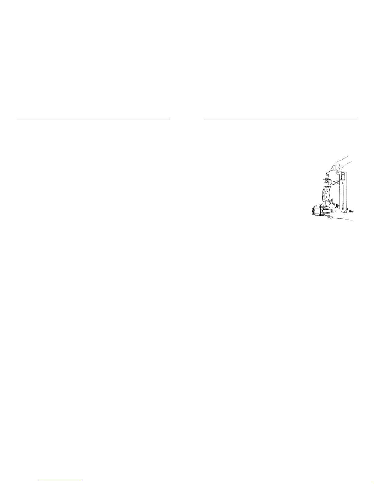
Lubrication
Disconnect tool from theair supply andremove all
fasteners. Apply 2 -3 dropsof airtool oil (pro-
vided) in theair inlet two- threetimes a day. If
the tool will be usedoutside in the winter, use a
wintergrade air tooloil to help keep frost from
forming insidethe tool. Donotuse other types of
lubricants on thistool, asother lubricants may
containchemicals harmful too-ringsandother
tool components. Drain compressor tanks and
hosesdaily.
Cleaning
Disconnecttool fromthe air supply and remove allfasteners. Brush tool
off using a parts cleaning brushor clean rag. Check area aroundtrigger
and workpiece contact, andclean as necessary. Pull pusherback to
latchedposition, and brush out staple entry areaof tool nose. Open E-Z
Clearlatch and brushout debris.Blowout confined areas aroundtool nose
usinglowpressurecompressedair.
OPERATION
TriggerCheck (Sequential)
Checktriggeroperationdailytoconfirm propersequentialoperation:
1.
Presstheworkpiececontact against a safe worksurface without
depressingthe trigger.
THETOOLMUST NOTCYCLE.
2.
Holdthetoolabove a safe worksurfaceand pull thetrigger without
depressingthe workpiececontact.
THE TOOL MUSTNOT CYCLE.
3.
Pull and hold thetrigger,and thenpress the workpiececontact
againsta safe worksurface.
THE TOOL MUST NOTCYCLE.
4.
With fingeroff trigger,pressthe workpiececontact againsta safe
worksurface. Keeptool pressed against work surface, and pull
trigger.
THETOOLMUST CYCLE
ONCE
.5.Thetriggermustreturn to the normal position each time finger
pressureis released.
TOOL OPERATION
SEQUENTIALOPERATION(Standard)
1.
Holdthetool securely using thehandgrip. Keep fingeroff trigger
until tool isin positionand you areready to drive a fastener. NOTE:
Depressingtrigger beforedepressingsafety bracketwill preventtool
fromactuating.
2.
Position the noseof thetool on theworkpiece,placing the noseat
thedesiredfastenerdrivingposition.
3.
Pressthe tooldownfirmly against the worksurface, fullydepressing
theworkpiececontact (safety bracket).
4.
Squeezethetriggeronceto drive afastener.
5.
Allowthetoolto reboundoff thework surface,andreleasethe trigger
to resettheworkpiececontact. Tool will notdrive anotherfastener
until triggeris released,and cannotbebump-firedwithsequential
triggerinstalled.
6.
Checkfastenerforcorrectdepthof drive, andif needed,adjust lower
elementtip toobtaindesiredfastenerdrive.
7.
If tool adjustments do not providethedesiredresults, make air
pressureadjustments at the compressor:Increase air pressureto
drive deeperor to driveintohardermaterials. Reduceair pressureto
reducedriveor todriveinto softermaterials. Forlongesttool and
partlife, alwaysuse the lowestair pressure necessaryto drive
fastenersto desireddepth.
8.
Positionthe toolfor drivingthe next fastener,and repeatthe above
procedure. Alwayskeep handsand other body parts awayfrom
areasbeingfastened.
CONTACTTRIP (BUMPFIRE)DRIVINGMETHOD(Optional)
Tooperate thistoolincontacttrip mode (bump-firing), remove thesequen-
tialtriggerprovided on thetool,andinstall the dual-actiontriggerprovided
withthe tool.
1.
Positionthenoseof thetoolover the work surface, near the area
wherethe first fastener is to be driven.
2.
Squeezeand hold the triggerin thedepressedposition.
3.
Bump the workpiece contact (safety) againstthe work surface at
eachpoint where a fastener is to be driven.
4.
Usinga bouncingmotion, continuemoving the tool into position for
eachfastenerdrive.
5.
When fasteningiscompleted,releasethetrigger.
Page 10
19
18
GRTSN150a PARTS LIST
GRTSN150a PARTS SCHEMATIC
ITEM
P/N
DESCRIPTION
1
GRTN1850
Hex.Soc.Hd.Bolt
2
GRTN1610
Deflector Bushing
3
GRTN1620
Deflector
4
GRTN1910
Hex.Soc.Hd.Bolt
5
GRTN3020
Cap6GRTN1630
Gasket, Cap
7
GRTN1670
Seal8GRTN2370
O-Ring
9
GRTN1640
Piston Stopper
10
GRTN2380
O-Ring
11
GRTN2350
O-Ring
12
GRTN1660
Spring
13
GRTN4230
Piston Head Valve
14
GRTN2390
O-Ring
15
GRTN4240
Cylinder Spacer
16
GRTN2150
O-Ring
17
GRTN2340
O-Ring
18A
GRTN4290
Driver Assembly
19
GRTN2120
O-Ring
20
GRTN4250
Cylinder
21
GRTN4260
Bumper
22
GRTN4270
Driver Guide
23A
GRTN4460
Body Assembly
24
GRTN4430
O-Ring
25
GRTN4450
End Cap
26
GRTN2220
O-Ring
27
GRTN2240
O-Ring
28
GRTN800
Valve29GRTN2100
O-Ring
30
GRTN2110
O-Ring
31
GRTN2170
O-Ring
32
GRTN805
Valve Plunger
33
GRTN830
Spring
34
GRTN2230
O-Ring
35
GRTN810
Plunger
36
GRTN820
Plunger Cap
37A
GRTN4470
Trigger Assy-SEQ.
38
GRTN2540
Spring Pin
39
GRTN150
Pin Trigger
40
GRTN2210
Gr ommet
ITEM
P/N
DESCRIPTION
41
GRTN4220
Contact Trip Guide
42
GRTN4280
Safety Spring
43
GRTN2660
E-Ring44GRTN1130
Adjusting Nut
45
GRTN2640
Ball, Steel
46
GRTN1100
Adjusting Post
47
GRTN930
Adjusting Spring
48
GRTN1090
Contact Trip Upper
49A
GRTN4320
SA, Door Latch
50
GRTN5060
Pusher Lever
51A
GRTN5070
Safety Lever Assy.
52
GRTN5080
Nose53GRTN5090
Rubber Pad
54
GRTN2510
Spring Pin
55
GRTN5100
Spring Pin
56
GRTN4400
Magazine Cap
57
GRTN1900
Hex.Soc.Hd.Bolt
58
GRTN4350
Magazine
59
GRTN5110
Bracket
60
GRTN4410
Spring
61
GRTN4380
Pusher
62
GRTN3950
Latch63GRTN4070
Spring
64
GRTN4370
Roller65GRTN4360
Spiral Pin
66
GRTN3980
Roller Pin
67
GRTN1840
Hex Soc. Hd. Bolt
68
GRTN1900
Hex Soc. Hd. Bolt
69
GRTN2590
Flat Washer
70
GRTN2060
Locknut
71
GRTN2950
Trigger Assy. - Bump
72
GRTN4480
End Cap
73
GRTN4110
Belt Hook
74
GRTN4140
O-Ring
75
GRTN4120
Cover Belt Hook
76
GRTN4440
C-Ring
77
GRTN4150
Belt Hook Assembly
A
GRDAK1200
Driver Assembly Kit
B
GRRBK1200
Rebuild Kit
C
MANSN
Operator’s Manual
D
CASESN150
Tool Case
Page 11
21
20
GRTSN100 PARTS LIST
GRTSN100 PARTS SCHEMATIC
ITEM
P/N
DESCRIPTION
1
GRTN1850
Hex.Soc.Hd.Bolt
2
GRTN1610
Deflector Bushing
3
GRTN1910
Hex.Soc.Hd.Bolt
4
GRTN1620
Deflector
5
GRTN6130
Cap, Machined
6
GRTN1630
Casket, Cap
7
GRTN1670
Seal8GRTN2370
O-Ring
9
GRTN1640
Piston Stopper
10
GRTN2380
O-Ring
11
GRTN2350
O-Ring
12
GRTN1660
Spring
13
GRTN4230
Piston Head Valve
14
GRTN2390
O-Ring
15
GRTN4240
Cylinder Spacer
16
GRTN2150
O-Ring
17
GRTN6240
O-Ring
18A
GRTN6260
Driver Assembly
19
GRTN6140
Cylinder
20
GRTN4260
Bumper
21
GRTN4270
Driver Guide
22A
GRTN4460
Body Assembly
23
GRTN4430
O-Ring
24
GRTN4450
End Cap
25
GRTN2210
Gr ommet
26
GRTN2540
Spring Pin
27
GRTN2220
O-Ring
28
GRTN2240
O-Ring
29
GRTN800
Valve30GRTN2100
O-Ring
31
GRTN6250
O-Ring
32
GRTN2170
O-Ring
33
GRTN805
Valve Plunger
34
GRTN830
Spring
35
GRTN2230
O-Ring
36
GRTN810
Plunger
37
GRTN820
Plunger Cap
38A
GRTN4470
Trigger Assy - SEQ.
39
GRTN150
Trigger Pin
40
GRTN4220
Guide, Contact Trip
ITEM
P/N
DESCRIPTION
41
GRTN4280
Spring, Safety
42
GRTN2660
E-ring43GRTN1130
Adjusting Nut
44
GRTN2640
Steel Ball
45
GRTN1100
Adjusting Post
46
GRTN930
Adjusting Spring
47
GRTN1090
Upper Safety Lever
48
GRTN6270
Lower Safety Lever Assy.
49
GRTN4340
Rubber Pad
50
GRTN6280
Hex.Soc.Hd.Bolt
51
GRTN6290
Hex.Soc.Hd.Bolt
52
GRTN6300
Bushing
53
GRTN6310
Safety Cover
54
GRTN6320
Lower Door, Machined
55A
GRTN6330
Magazine
56
GRTN6340
Spring Stopper
57
GRTN6350
Pusher
58A
GRTN6360
SA Magazine
59
GRTN6370
Magazine Latch
60
GRTN6380
Magazine Latch Spring
61
GRTN2060
Locknut
62
GRTN6390
Magazine Cap
63
GRTN6400
Spring Pin
64
GRTN1880
Hex.Soc.Hd.Bolt
65
GRTN6410
Magazine Spring
66
GRTN6420
Spring Latch
67
GRTN6430
Guide Stem
68
GRTN6440
Hex.Soc.Hd.Bolt
69
GRTN2610
Flat Washer
70
GRTN2950
Trigger Assembly - Bump
71
GRTN4480
End Cap
72
GRTN4110
Belt Hook
73
GRTN4140
O-Ring
74
GRTN4120
Spring Plate
75
GRTN4440
C-Ring
76
GRTN4150
Belt Hook Assembly
A
GRDAK2100
Driver Assembly Kit
B
GRRBK2100
Rebuild Kit
C
MANSN
Operators Manual
D
CASESN100
Tool Case
Page 12
23
22
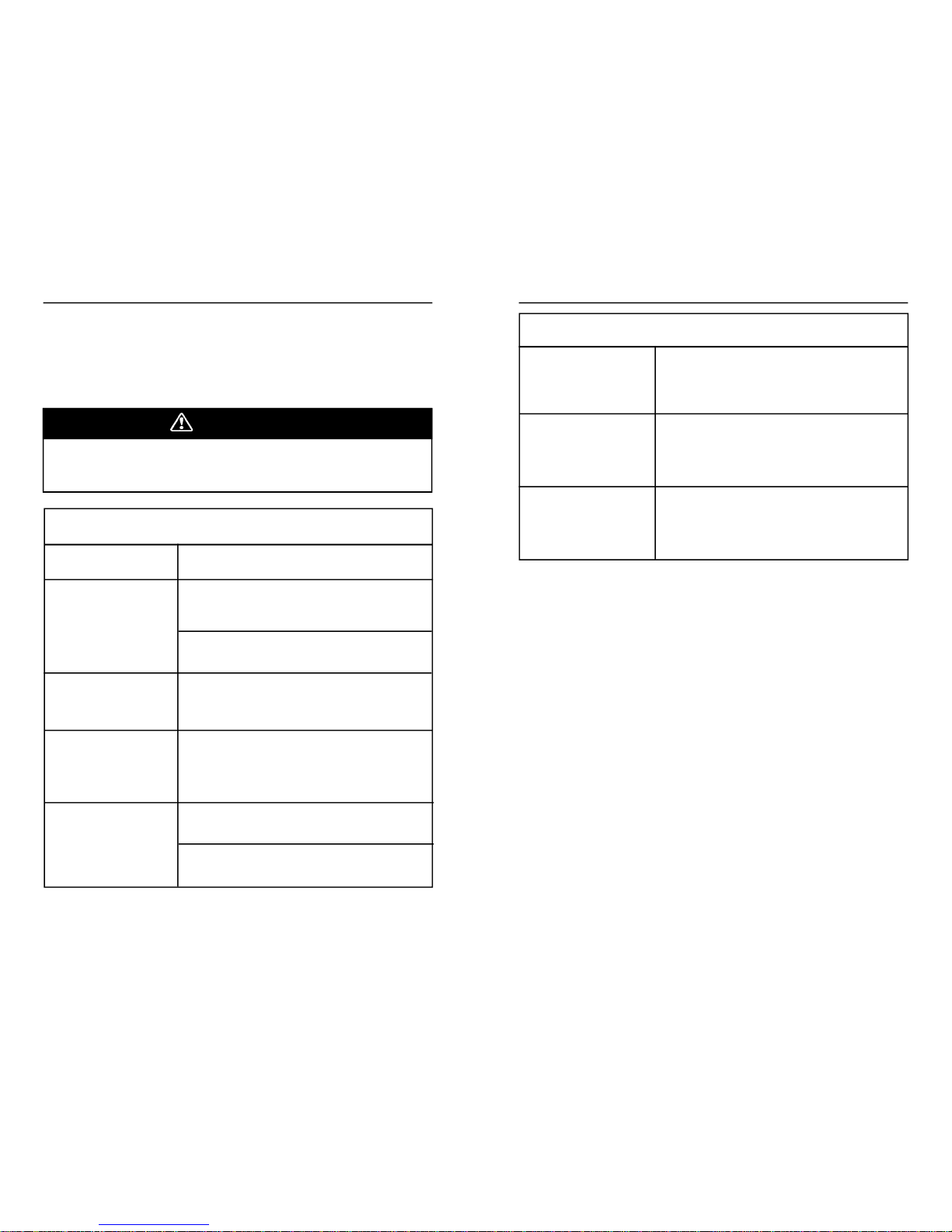
TROUBLESHOOTING
TOOL TROUBLESHOOTING
Your pneumatic fasteningtool has beendesignedfor longlife andtrouble-
free operation. However,if operatingproblems arise, pleaseuse the
troubleshootinginformation belowto determinehowto remedy theprob-
lem.
TROUBLESHOOTING
FASTENERDRIVINGPROBLEMS
Alwaysdisconnecttool from airsupplybeforeperforming any service on
tool. Correcting a problem whilethe tool is pressurized may resultin
injuryfromfastenerdischargeor tool operation.
DANGER
Toolleaksair.
Checkforsourceof leak,andtighten fittings
and screws as required. Discontinueusing
tool if air leaks at trigger area or from cap
exhaust. Contact your dealer.
Tooloperates,but no
fasteneris driven.
Toolwon’toperate-
staplejammed in tool
nose,preventingtool
fromoperating.
Removejammed fastener. Checkmagazine
for incorrect, bent, or loose fasteners,and
discard. Reload using Grip-Rite™ staples.
Checknosefor jammed fastener. Clear jam
andreloadmagazine. Checkstaplestripsfor
smoothfeedinginmagazine.
Fastenersdo not drive
completely.
ATCOMPRESSOR: Increaseair pressure.
Donot exceed 110 psi/7.6bar
Fastenersdo notdrive
completelywhen
driving in quick succes-
sion.
Inadequateairflow. Uselargerdiameter hose.
Usecompressorwith larger storage tank.
Keep hose lines short. Checkair hose for
kinks or otherrestrictions.
Fastenersdrive too
deeply.
ATCOMPRESSOR: Reduce air pressure.
(Donotreducebelow70 psi/4.8 bar.)
PROBLEM
CORRECTIVEACTION
Fastenersdo not drive
completelyafter air
pressureis increased.
Driverbladewornor broken. See dealerfor
replacement.
FASTENERDRIVINGPROBLEMS
ATTOOL: Turn adjustment dial toincrease
stapledrive depth. Add 2 - 3drops of airtool
oil to inlet.
ATTOOL: Turn adjustment dial todecrease
stapledrivedepth.
TOOL CHECKS
Keep your stapler in top working condition bychecking it daily. See your
Grip-Rite™ dealerfor serviceif partor operatingproblemsarefound. Never
usea malfunctioning tool - it could resultin serious injury.
WorkpieceContact& Trigger
Checkworkpiececontactforproper operationbeforeeachuse. Workpiece
contactmust movefreelyandreturn to extendedpositionwhenlifted from
workpiece. Triggermustoperatefreely.
DailyInspection
•
Checkfor broken, damaged,or excessively wornparts,and repair
orreplaceas needed.
•
Checkfor airleaksat trigger,cap, and nose. Disconnect tool from
air supplyimmediately ifleaksarepresent,and see dealer for
service.
•
Make sureall screws are tightened securely.
Page 13

2524PNEUMATIC TOOL/COMPRESSOR WARRANTY
Pneumatic nailers, staplers& compressorsmarketedunderthe
GRIPRITE
TM
brandarewarrantedtobefreefromdefectsin work-
manship& materials (except rubbero-rings,bumpers,seals,driver
blades,dipsticks,& air filters) for a period ofoneyear from thedate
of originalpurchase.
Thiswarranty will notapply when:
•
Theoriginalreceipt (or copy of theoriginal receipt), showingthe
originalpurchasedate, is not providedwithtools/compressorssent
inforwarrantyrepair
•
Thetool/compressorhasbeenmisused, abusedor improperly
maintained
•
Alterationshave beenmadeto the original tool/compressor
•
Repairshavebeenattempted/madeto the originaltool/compressor
byany entity other thanaproprietary
GRIP-RITE
®
service/warranty
centerorauthorized service/warrantycenter
•
Non-
GRIP-RITETOOLS
TM
/GRIP-RITECOMPRESSORS
TM
/
parts
havebeenused
•
Thetool hassuffered any physical damage due to the useof non-
GRIP-RITE
®
approvedfasteners*
•
Repairsare requireddueto normal wear& tear
•
Thetool/compressorhas beeninadequatelypackagedleadingto
damagein-transitto theservice/warrantycenter.
*Approvedfastenersincludethefollowingbrands
GRIP-RITE
FAS’NERS
TM
,FAS’NERS UNLIMITED
TM
INNO EVENTSHALL
PRIMESOURCE
®
BE LIABLE FOR ANYINDI-
RECT,ACCIDENTALOR CONSEQUENTIALDAMAGE FROM THE SALE
OR USE OF THESE PRODUCTS. THIS DISCLAIMER APPLIES BOTH
DURING& AFTER THETERMOF WARRANTY.
THIS IS OUR WARRANTY & IS EXPRESSLYIN LIEU OF ALL OTHER
WARRANTIES,EXPRESS OR IMPLIED,INCLUDINGTHE WARRANTIES
OF MERCHANTABILITYAND FITNESS FORA PARTICULARPURPOSE
(EXCEPTAS MAYBE OTHERWISE PROVIDEDBYLAW).
THISLIMITEDWARRANTY GIVESYOU SPECIFIC LEGAL RIGHTS,AND
YOUMAYALSO HAVEOTHERRIGHTS,WHICHVARY, FROM STATETO
STATE.
WARRANTY
PNEUMATICTOOL/COMPRESSORSERVICEINFORMATION
Shouldany mechanical problemsdevelopduring the life of your
equipmentthe followingoptionsareavailablefor service and parts:
•
Call(800)676-7777whereyou will beroutedtothe nearest
GRIP-
RITE
®
distributioncenter and directed to the nearestauthorized
service/warrantycenter.
•
Loggingon to our websiteat
www.grip-rite.com
whereyou will
find a list of ourauthorized service centers.
•
Contactthe
GRIP-RITE
®
FactoryWarrantyCenter directly at
Phone:(800)207-9259or Fax: (800)207-9614
•
InCanada,call(866)512-1418
STEPSTO TAKE WHENSHIPPING TOOLS
•
Adequately packagethe producttoavoid damage in-transit(in
thecaseof pneumatic tools,the original blow moldplastic
carryingcase is consideredadequate packaging).
•
Providetheoriginal/copyof receiptshowingthe original purchase
date.•Insureyour shipment with the shipping company.
PRIMESOURCE
®
willnot beresponsibleforanytool/compressorthat
is lost or damaged by the shipperon route to the
PRIMESOURCE
®
service/warrantycenter.
WARRANTY
Page 14

27
26
NOTES
NOTES
Page 15

28
USE GENUINE GRIP-RITE
®
FASTENERS FOR BEST
PERFORMANCE
MANSN
 Loading...