

Grip Rite GRTSN150a, GRTSN100 Operator's Manual
1
OPERATOR’SMANUAL
AND PARTS LIST
MODEL GRTSN150a STAPLER
MODEL GRTSN100 STAPLER
32IMPORTANT SAFETY INFORMATION
Youmust readthisentiremanualandfamiliarizeyourselfwithall
safety,operating, andserviceinstructionsbefore loading,handling,
orusingyour tool. Whenusedcorrectly, pneumatic fastening
toolsprovide a lightweight,powerful,and safemeansof fastening.
Usedimproperly,these tools can cause serious injury to youand
thosearoundyou.
TABLE OF CONTENTS
TABLE OF CONTENTS
-------------------------------
3
GRTSN100 SPECIFICATIONS
----------------------
4
GRTSN100 Fastener Selection Chart
--------
4
GRTSN150a SPECIFICATIONS
---------------------
5
GRTSN150a Fastener Selection Chart
------5SAFETY
----------------------------------------------------
6
TOOL PARTS
------------------------------------------
10
PART DESCRIPTIONS
------------------------------
11
GRTSN150a OPERATION
--------------------------
12
Loading Staples
----------------------------------
12
Adjusting Staple Drive
--------------------------
13
Clearing Staple Jams
---------------------------
13
GRTSN100 OPERATION
----------------------------
14
Loading Staples
----------------------------------
14
Adjusting Staple Drive
--------------------------
15
Clearing Staple Jams
---------------------------
15
TOOL OPERATION
-----------------------------------
16
MAINTENANCE
---------------------------------------
17
Lubrication
-----------------------------------------
17
Cleaning
--------------------------------------------
17
Trigger Check
-------------------------------------
17
GRTSN150a PARTS SCHEMATIC
---------------
18
GRTSN150a PARTS LIST
--------------------------
19
GRTSN100 PARTS SCHEMATIC
-----------------
20
GRTSN100 PARTS LIST
----------------------------
21
TROUBLESHOOTING
-------------------------------
22
TOOL CHECKS
----------------------------------------
23
WARRANTY
--------------------------------------------
24
NOTES
---------------------------------------------------
26

5
4
GRTSN150a SPECIFICATIONS
GRTSN150a SPECIFICATIONS
MODEL
GRTSN150a
FASTENERRANGE
3/4” - 1 1/2 ” (19 mm - 38 mm)
FASTENERTYPE
18 Ga. Staples
CROWNSIZE
1/4” (6.4 mm) Narrow Crown
MAGAZINE CAPACITY
140STAPLES
MAX AIR PRESSURE
110 psi (7.6 bar)
MINAIR PRESSURE
70 psi (4.8 bar)
TOOL WEIGHT
2.8 lbs. (1.3 kg)
TOOL LENGTH
11.25” (28 cm)
TOOLHEIGHT
10.15” (26 cm)
TOOL WIDTH
2.25” (5.7 cm)
STANDARDTRIGGER
Sequential
ACCESSORYTRIGGER
Dual Action (Bump/Trigger Fire)
AIR INLET
1/4NPT
AIRCONNECTION
Male Quick Connect Coupler
LUBRICATION
10W Air Tool Oil (Provided)
NOISE CHARACTERISTIC VALUES IN ACCORDANCE WITH ISO 3774,ISO 11201:
A-weighted single-event sound
pressure level at operator’s position
----------------------------------
LpA, 1s = 89 dBA
A-weighted single-event sound power level
-----------------------
LwA, 1s = 100 dBA
A-weighted single-event surface sound
pressure level
----------------------------------------------------------------
LpA, 1s = 87 dBA
VIBRATION CHARACTERISTIC VALUES IN ACCORDANCE WITH ISO 8862-1
Weighted root mean square acceleration
----------------------------
= 1.9 m/s
2
For best results, use Grip-Rite™ collated fasteners.
LEG
BOX
CROWN
WIRE
GALVANIZED
LENGTH
QTY.
SIZE
GA.
STEELSKU
3/4” (19 mm)
5M
1/418GRL11
7/8” (22 mm)
5M
1/418GRL12
1” (25 mm)
5M
1/418GRL13
1-1/8” (29 mm)
5M
1/418GRL14
1-1/4” (32 mm)
5M
1/418GRL15
1-1/2” (38 mm)
5M
1/418GRL17
FASTENER SELECTION CHART
GRTSN100 SPECIFICATIONS
GRTSN100 SPECIFICATIONS
MODEL
GRTSN100
FASTENERRANGE
1/2” - 1 ” (13 mm - 25 mm)
FASTENERTYPE
18 Ga. Staples
CROWNSIZE
1/4” (6.4 mm) Narrow Crown
MAGAZINE CAPACITY
110 STAPLES
MAX AIR PRESSURE
110 psi (7.6 bar)
MINAIR PRESSURE
70 psi (4.8 bar)
TOOL WEIGHT
2.7 lbs. (1.2 kg)
TOOL LENGTH
9.75” (24.8 cm)
TOOLHEIGHT
8.6” (21.8 cm)
TOOL WIDTH
2.25” (5.7 cm)
STANDARDTRIGGER
Sequential
ACCESSORYTRIGGER
Dual Action (Bump/Trigger Fire)
AIR INLET
1/4NPT
AIRCONNECTION
Male Quick Connect Coupler
LUBRICATION
10W Air Tool Oil (Provided)
NOISE CHARACTERISTIC VALUES IN ACCORDANCE WITH ISO 3774,ISO 11201:
A-weighted single-event sound
pressure level at operator’s position
----------------------------------
LpA, 1s = 89 dBA
A-weighted single-event sound power level
-----------------------
LwA, 1s = 100 dBA
A-weighted single-event surface sound
pressure level
----------------------------------------------------------------
LpA, 1s = 87 dBA
VIBRATION CHARACTERISTIC VALUES IN ACCORDANCE WITH ISO 8862-1
Weighted root mean square acceleration
----------------------------
= 1.9 m/s
2
For best results, use Grip-Rite™ collated fasteners.
LEG
BOX
CROWN
WIRE
GALVANIZED
LENGTH
QTY.
SIZE
GA.
STEELSKU
1/2” (13 mm)
5M
1/418GRL08
5/8” (16 mm)
5M
1/418GRL10
3/4” (19 mm)
5M
1/418GRL11
7/8” (22 mm)
5M
1/418GRL12
1” (25 mm)
5M
1/418GRL13
FASTENER SELECTION CHART
7
6
SAFETY
SAFETY
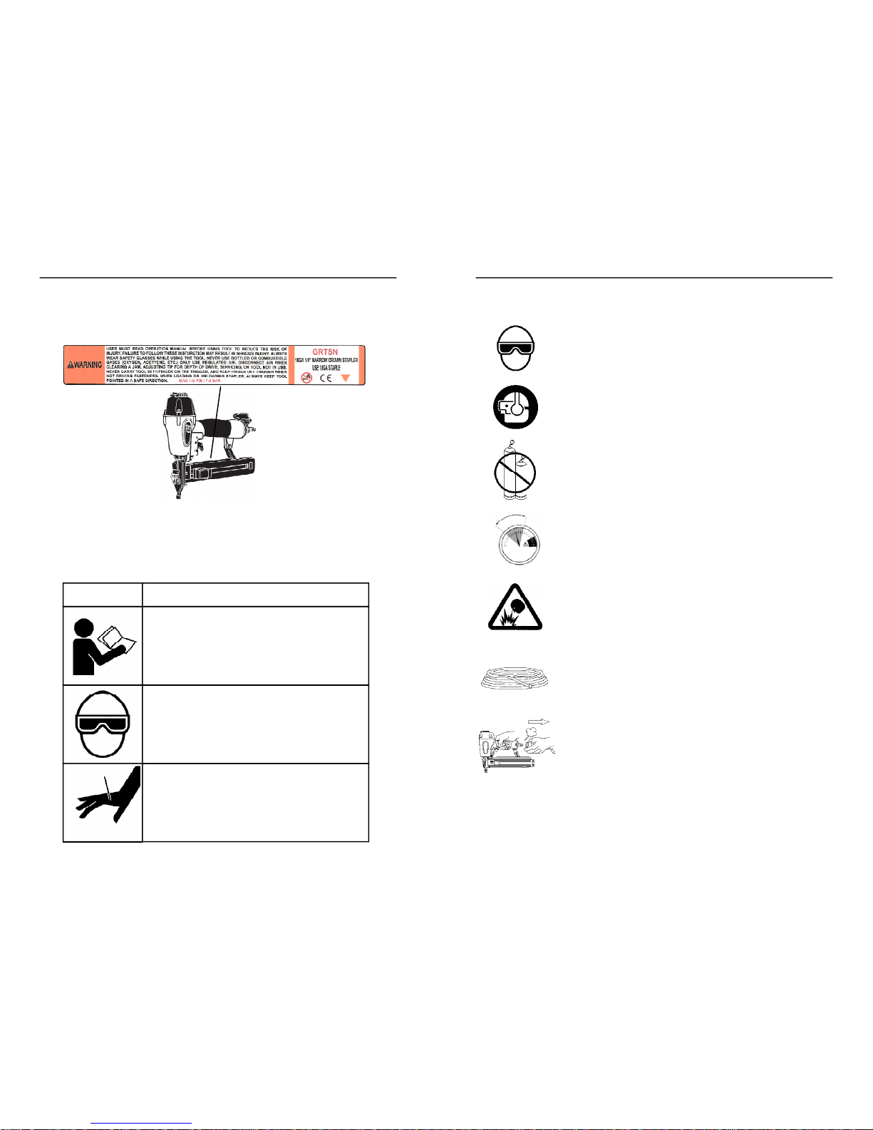
SAFETY LABELS
This pneumatic fastening tool includes a warning label to help remind you of
important safety information when operating the tool. The safety label must be
legible at all times, and must be replaced if it becomes worn or damaged.
SYMBOL
DESCRIPTION
READTHE MANUAL
-Themanualcontains
importantsafetyand operatinginstructions
that must befollowed. All tool users must
readthe manualbefore usingthetool.
WEARSAFETYGLASSES
-Tooloperator
and bystandersmust wear safety glasses
withsideshield thatmeetANSI Z87.1
requirements.
RISKOF PERSONALINJURY
-Failureto
followall safety and operatinginstructions,
or misuse of the tool, can result inserious
injuryto tool operator and bystanders.
WEARSAFETYGLASSES
Always wear safety glasses with side shields that meet ANSI
Z87.1 requirements when operating the tool. Make sure all
others in work area wear safety glasses.
WEARHEARINGPROTECTION
Wear hearing protection to protect your hearing from noise.
Prolonged exposure to loud noise can result in hearing loss.
NEVEROPERATETHETOOLWITHOXYGENOR OTHER
BOTTLEDGASES
Oxygen and other reactive or high-pressure bottled gases
can cause the tool to explode. Use clean, dry regulated
compressed air from a properly operating air compressor.
DONOTEXCEEDMAXIMUMRECOMMENDEDOPERATINGAIR
PRESSURE OF110 PSI/7.6 Bar.
Exceeding the maximum recommended air pressure can
cause the tool housing to burst, or cause premature failure of
components.
NEVERCONNECTTHE TOOLTO AN AIRSUPPLYTHATHAS
THEPOTENTIALTO EXCEED180 PSI/12.4Bar.
Using a regulated air supply with a line or tank pressure
greater than 180 psi can cause the tool to burst if the air line
regulator fails suddenly.
USEAN AIRHOSE RATED FOR 180 PSI/12.4Bar OR
GREATER
Always use air hose rated to handle 180 psi or the maximum
potential pressure of the air supply.
ONLYUSEARELIEVING-TYPEAIRCOUPLINGINTHE TOOL
AIRINLETOPENING.
Use of a non-relieving air coupling on the tool can trap air
inside the tool housing, and allow the tool to drive a fastener
even after the air hose has been disconnected.
SAFETY INSTRUCTIONS
110psi
4.8bar
70psi
7.6bar
SAFETY SYMBOLS
These safety symbols provide a visual reminder of basic safety
rules, and the personal injury hazard that may arise if all safety and
operating instructions are not followed. Make sure you understand
the meaning of each of these symbols, and protect yourself and
others by obeying all safety and operating instructions.
9
8
SAFETY
SAFETY
DONOTATTEMPTTO OPERATETHETOOLIFTHE TOOL’S
OPERATINGCONTROLSHAVEBEENMODIFIEDORARENOT
WORKINGPROPERLY.
Attempting to use a tool with modified or malfunctioning
trigger or workpiece contact can result in a fastener being
driven unintentionally.
USECORRECTFASTENERS
Only use the correct fastener for the tool. Using fasteners
with incorrect specifications can jam the tool or cause
serious injuries.
USETHECORRECTFASTENERSFORTHEAPPLICATION.
Using the wrong fasteners can cause the workpiece to split
and allow the fastener to fly free.
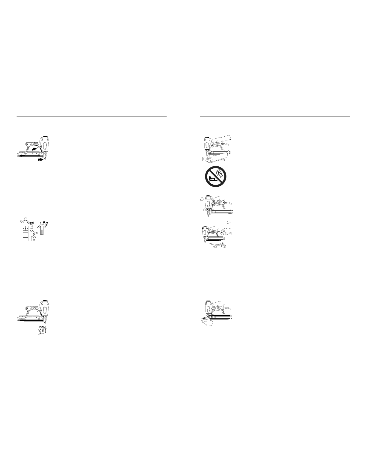
KEEPTOOL POINTEDINA SAFEDIRECTIONWHENLOADING
FASTENERS.
Never point the tool at yourself or anyone else when loading
fasteners.
DONOTLOAD TOOLWITHTRIGGERORWORKPIECE
CONTACTDEPRESSED.
Depressing the trigger or workpiece contact during loading
can result in an unintentional fastener drive if both devices
are accidentally actuated at the same time.
KEEPFINGEROFFTRIGGERUNTILTOOLIS INPOSITIONTO
DRIVEAFASTENER.
An unexpected bump or sudden contact with your body or that
of a bystander can result in serious injuries.
AVOIDDRIVINGFASTENERSINTOKNOTS,ONTOPOF
OTHERFASTENERS,ATWORKPIECEEDGES,ORINTO
BRITTLEMATERIALS.
Driving fasteners into extremely hard materials, or driving into
workpiece edges, can cause fasteners to deflect away from
the workpiece. Flying fasteners can cause serious injuries.
SAFETY INSTRUCTIONS
KEEPHANDSANDBODYPARTSAWAYFROMAREABEING
FASTENED.
Fasteners can deflect and turn as they are being driven into
the workpiece, and penetrate fingers, hands, and other body
parts that may be in the fastening area.
DONOTOVERREACHORWORKWHILEON UNSTABLE
FOOTING
If you lose your balance while fastening, you could drive a
fastener into yourself or a bystander.
DONOTUSETOOLIFTOOL MALFUNCTIONSORBEGINS
LEAKINGAIR.
Operating a malfunctioning tool can result in an unexpected
fastener discharge and injury to yourself or others.
DISCONNECTTHETOOLFROMTHEAIRSUPPLYTORE-
LOAD,CLEARJAMS,ORPERFORMMAINTENANCE.
Never attempt to reload a tool, clear a jam, or perform
maintenance without first disconnecting the air supply.
NEVERLEAVEALOADED,PRESSURIZEDTOOL
UNATTENDED
A loaded, pressurized tool could be picked up or handled by
someone who is unfamiliar with the tool or that has not read
the tool manual.
KEEPTOOLSOUTOFTHEREACHOFCHILDREN
Place the tool back in the tool box after use, and store the tool
out of reach.
DONOTMODIFYTOOL
Modifications can cause a tool to be unsafe and can cause
the tool to operate improperly.
SAFETY INSTRUCTIONS
 Loading...