

Page 1
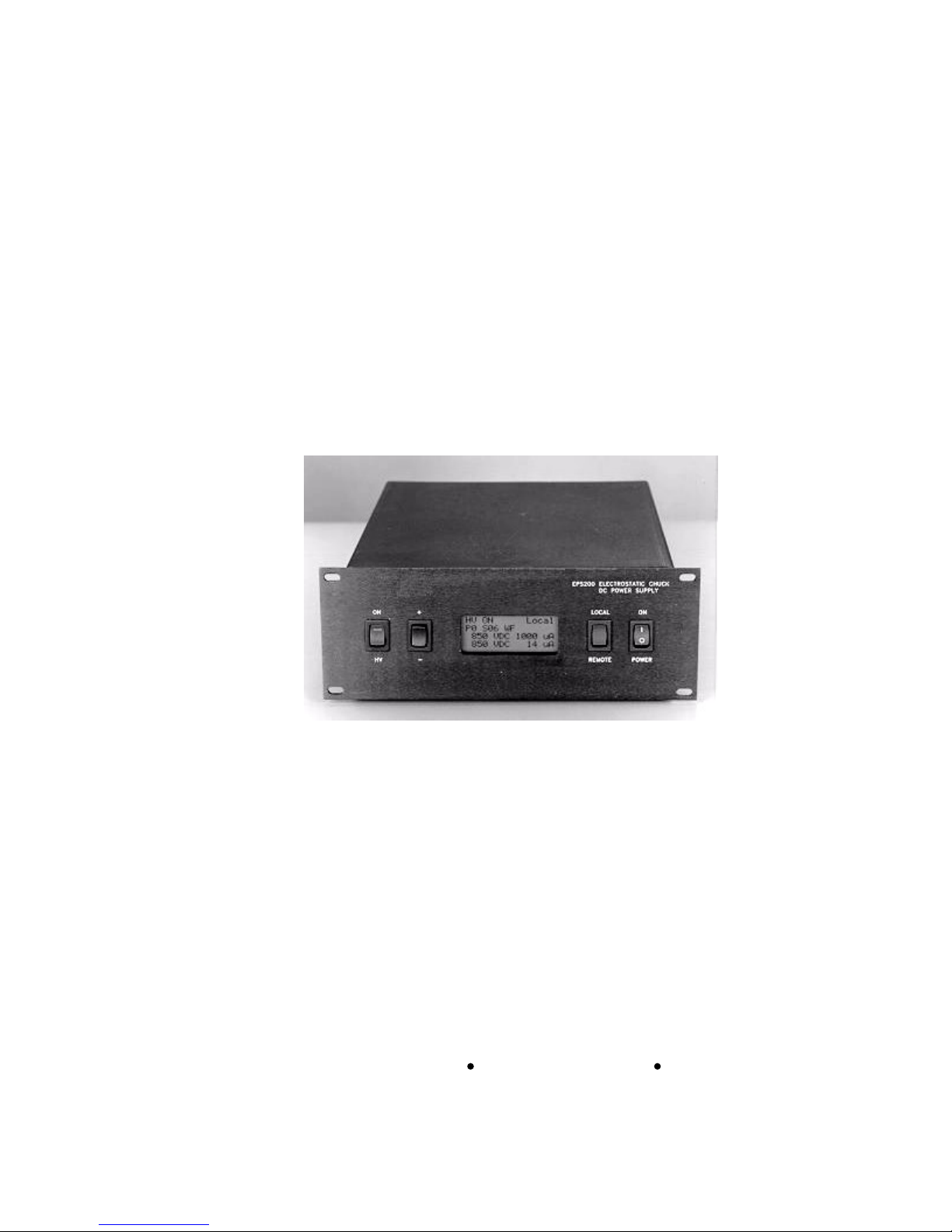
EPS200
Electrostatic Chuck DC Power Supply
Users Manual
http://www.GrippingPower.com
G r i p p i n g P o w e r , I n c.
11930 44th St. North, Suite B
Clearwater, FL 33762
(727) 572
-4100
Page 2

Gripping Power, Inc
2 EPS200 User s Manual
Products newly manufactured by Gripping Power, Inc.
(GPI), Clearwater, Florida are
warranted against defects in materials and workmanship for a period of one year from the
original date of delivery.
This warranty does not cover damage from, or failure attributable to, acts of nature, ab
use,
misuse, improper usage, faulty installation, or any modifications not expressly authorized in
writing by GPI.
Within the warranty period, GPI will, at our option, repair or replace the item determined to be
defective within the terms of this warranty
. After the warranty period, there will be charges
rendered for any repairs, adjustments or upgrades made to the product by GPI, including, but
not limited to, charges for shipping, insurance, parts and labor.
Factory reconditioned and refurbished GPI eq
uipment is warranted against defects in materials
and workmanship for a period of 90 days from the date of delivery.
GPI is not responsible or liable for indirect, special, or consequential damages arising out of, or
in connection with, the use or perfor
mance of the product or other damages with respect to loss
of property, loss of revenues or profit, or costs of removal, installation or reinstallation.
Except as provided herein, GPI makes no express warranties, and any implied warranty,
including warra
nties of merchantability or fitness for a particular purpose, is limited to a period
of ninety days from the original date of delivery.
This warranty gives you specific legal rights. You may have additional rights that vary from
state to state.
Do
cument G29303-01, Rev A (printed July 2005)
No part of this publication may be reproduced, stored in a retrieval system, or transmitted, in
any form or by any means without prior written permission of Gripping Power, Inc.
The information contained herein
is subject to change without notice.
Copyright (c) 2005 by Gripping Power, Inc. (USA).
All rights reserved.
http://www.GrippingPower.com
Page 3

Gripping Power, Inc
3 EPS200 User s Manual
Table of Contents
1. INTRODUCTION
1.1. Introduction
5
1.2. Features
5
1.3. Local Operation
5
1.4.
Remote Operation 5
1.5. Programmability
5
2. INS
TALLATION
2.1. Installation
6
2.2. AC Power Requirements
6
2.3. RS-232 Serial Interface
6
2.4. Digital/Analog Remote Interface
6
2.5. High Voltage Connections
6
2.6. Load Connections
7
3. OPERATION
3.1. Operation
8
3.2. The Front Panel
8
3.3. Setting the Operating Mode
8
3.4. Local Operating Mode
9
3.5. Digital R
emote Mode 9
3.6. Analog Remote Mode
9
3.7. RS-232 Remote Mode
10
3.8. RS-232 Command Lockout
11
3.9. DeviceNet Mode
11
4. PROGRAM AND CONTROL COMMANDS
4.1. Introduction
12
4.2. High Voltage Control Commands
12
4.3.
Status Information Commands
14
4.4. T1, T2 and T3 Timer Commands
16
4.5. Digital Output
Control
18
5. PROGRAMMING
5.1. Introduction
19
5.2. Program Specific Commands
19
5.3. Special Program Commands
19
5.4. Program Control Commands
20
5.5. Entering Program Commands
21
Page 4

Gripping Power, Inc
4 EPS200 User s Manual
6.
TROUBLESHOOTING
6.1. Introduction
23
6.2. Overload Fault
23
6.3. Alarm Output
23
6.4. No Output
23
6.5. Component Replacement
23
APPENDIX A - Programming Examples
APPENDIX B - Technical Specifications
APPENDIX C - RS-232 Connector Specification
APPENDIX D - Remote Control Interface Specifications
APPENDIX E - Ordering and Service Information
Page 5
Gripping Power, Inc
5 EPS200 User s Manual
1. INTRODUCTION
1.1. Introduction. The Gripping Power, Inc. EPS200 high voltage DC power supply was
designed to drive semiconductor wafer electrostatic chucks in all process conditions, with
years of reliable performance.
1.2. Features.
The EPS200 is microprocessor based and is fully programma
ble. One local
and three remote operating modes are provided. The unit is available with either 1kV or
2.5kV true floating, bipolar outputs. The high voltage output is continuously variable, with
output load voltage tracking and user defined current limi
ting. A back-lit LCD displays
voltage, current and status information.
1.3. Local Operation.
The local operation mode provides the user the means of testing
programs and diagnosing hardware problems, via the EPS200 front panel, without the use of
a host
computer interface.
1.4. Remote Operation.
Serial RS-232, digital, and analog remote control modes are
provided. All electrical interfaces are isolated from the high-voltage output and are ground
referenced. The high-voltage can be turned on and off via a s
ingle digital bit input. An
analog input is provided for remote high voltage control. Two digital output signals are
provided to minimize interface problems when replacing mechanical chuck mechanisms
with electrostatic chucks. A digital alarm output sign
al is also provided.
1.5. Programmability.
The EPS200 can store up to ten user defined programs that control
the chuck and dechucking operation. Each program can be up to 32 steps long. The unit
may be directed to execute any one of the ten stored programs,
giving the user maximum
flexibility in both the setup phase, when testing chuck reliability, and in production
operation. All ten of the EPS200 programs are stored in nonvolatile RAM and can be
downloaded to a host computer. The EPS200 programming comman
d set provides the user
optimum flexibility for developing sophisticated chucking algorithms for multiple process
conditions.
Page 6
Gripping Power, Inc
6 EPS200 User s Manual
2. INSTALLATION
2.1. Installation.
The EPS200 is designed for installation in a standard 9.5 inch equipment
half-rack or it can be use
as a desktop instrument.
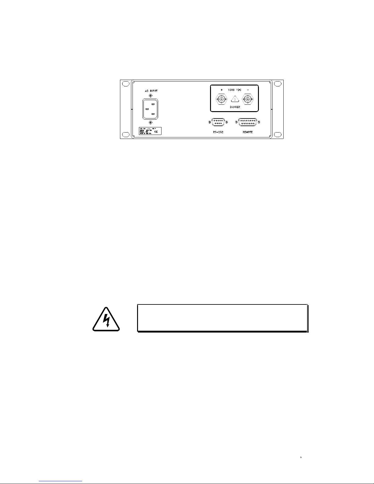
Figure 2.1 - EPS200 Rear Panel
2.2. AC Power Requirements.
Power is supplied to the unit via the IEC 320 receptacle,
located on the real panel. The AC power cord provided with the EPS 200 is for North
Amer
ican usage at 120 VAC, 60 Hz. The unit can operate from 90 to 264 VAC at a line
frequency of 47 to 63 Hz and is internally fused for safety. Contact the factory for power
cords and accessories for installation and operation in other areas of the world.
2.3. RS-232 Serial Interface.
The RS-232 serial interface is a 9-pin, D-style subminiature
female connector, located on the rear panel. The unit is configured as DCE without modem
control lines such as CTS, RTS or DTR. The host terminal or computer should be
configured for 9600 baud, no parity, eight data bits, one stop bit. When uploading ASCII
text programming files, use a 100 millisecond line-to-line delay. Additional information
detailing the communication specifications and serial interface is availabl
e in Appendix C.
2.4. Digital/Analog Remote Interface.
The digital and analo
g interface is a 15-pin, D
style subminiature female connector, located on the rear panel. The remote high voltage go
on, analog setpoint, clamp is up, clamp is down, and alarm outputs are contained in this
connector. The connector definition is shown in
Appendix D.
2.5. High Voltage Connections. The power supply high voltage output is via the two BNC
connectors located at rear of the unit. The outer ring of these connectors is electrically
isolated from ground and is not referenced to the high-voltage o
utput. Connections to the
outer conductors can be terminated at a common ground point, or left floating without
affecting the performance of the EPS200.
WARNING:
High-voltages are produced by the EPS200.
Installation and operation of the unit should be performed
only by qualified and authorized personnel.
Page 7
Gripping Power, Inc
7 EPS200 User s Manual
2.6. Load Connections
. For proper operation and continued reliability, the high voltage
outputs of the EP
S200 must be electrically isolated from extremely high DC bias voltages,
high power RF fields or other sources of potential damage.
It is highly recommended that only accessories manufactured, or specifically authorized, by
Gripping Power, Inc. should b
e used with the EPS200 when developing an electrostatic
chuck application for plasma processes. Gripping Power, Inc. can provide interconnect
cables, RF decouplers and other accessories to meet any specific need.
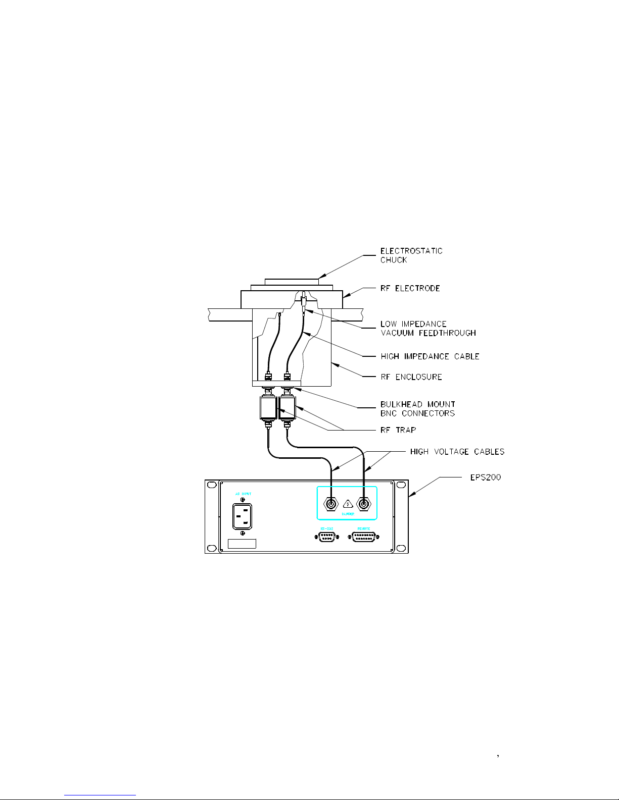
A typical electrostatic chuck applicatio
n for a semiconductor plasma process is shown
below. All of the components are required for proper chucking operation and protection of
the EPS200 power supply.
Figure 2.2 - Typical Installa
tion
Page 8
Gripping Power, Inc
8 EPS200 User s Manual
3. OPERATION
3.1. Operation.
The EPS200 is specifically designed to operate electrostatic chucks and it
provides many features that are not normally associated with a general purpose, high
-
voltage power supply.
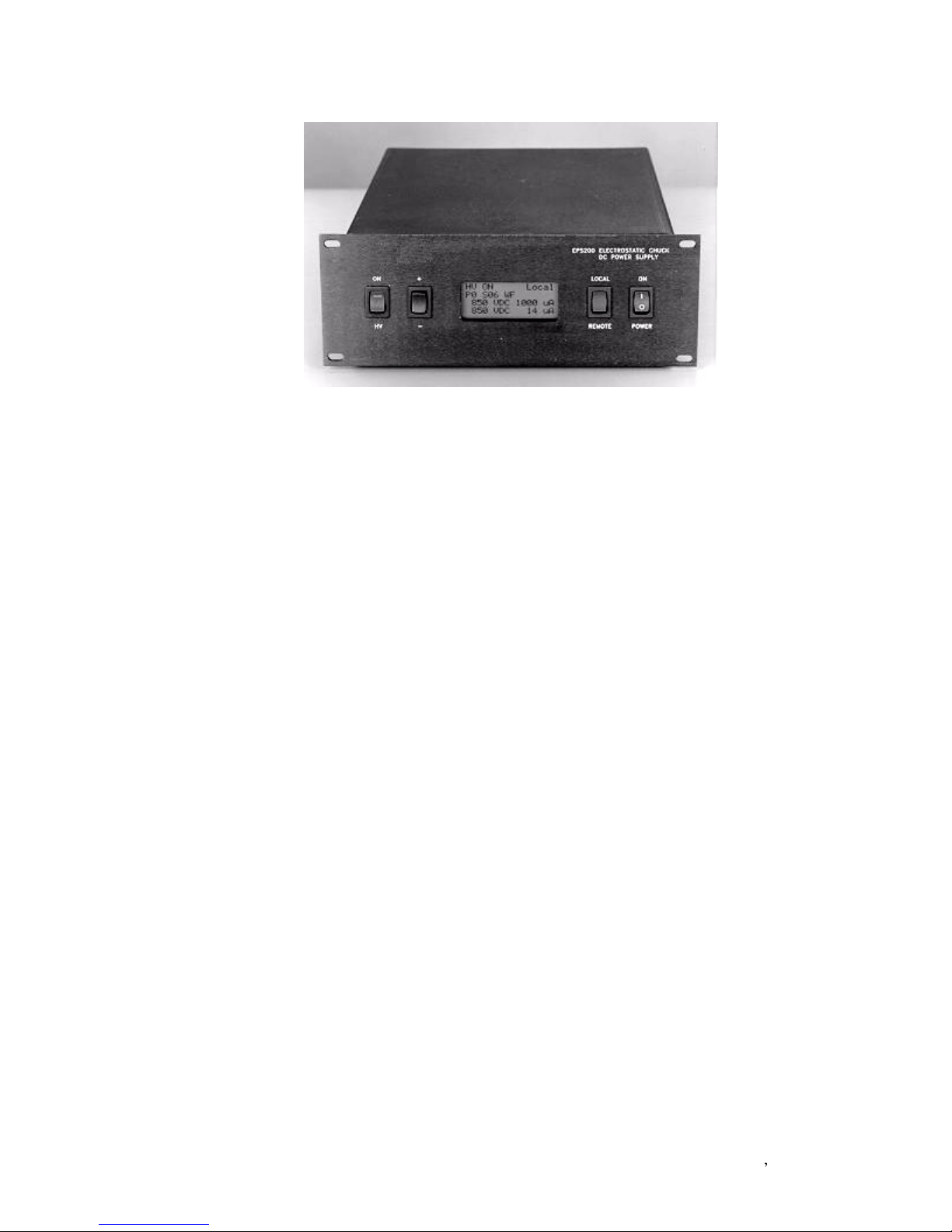
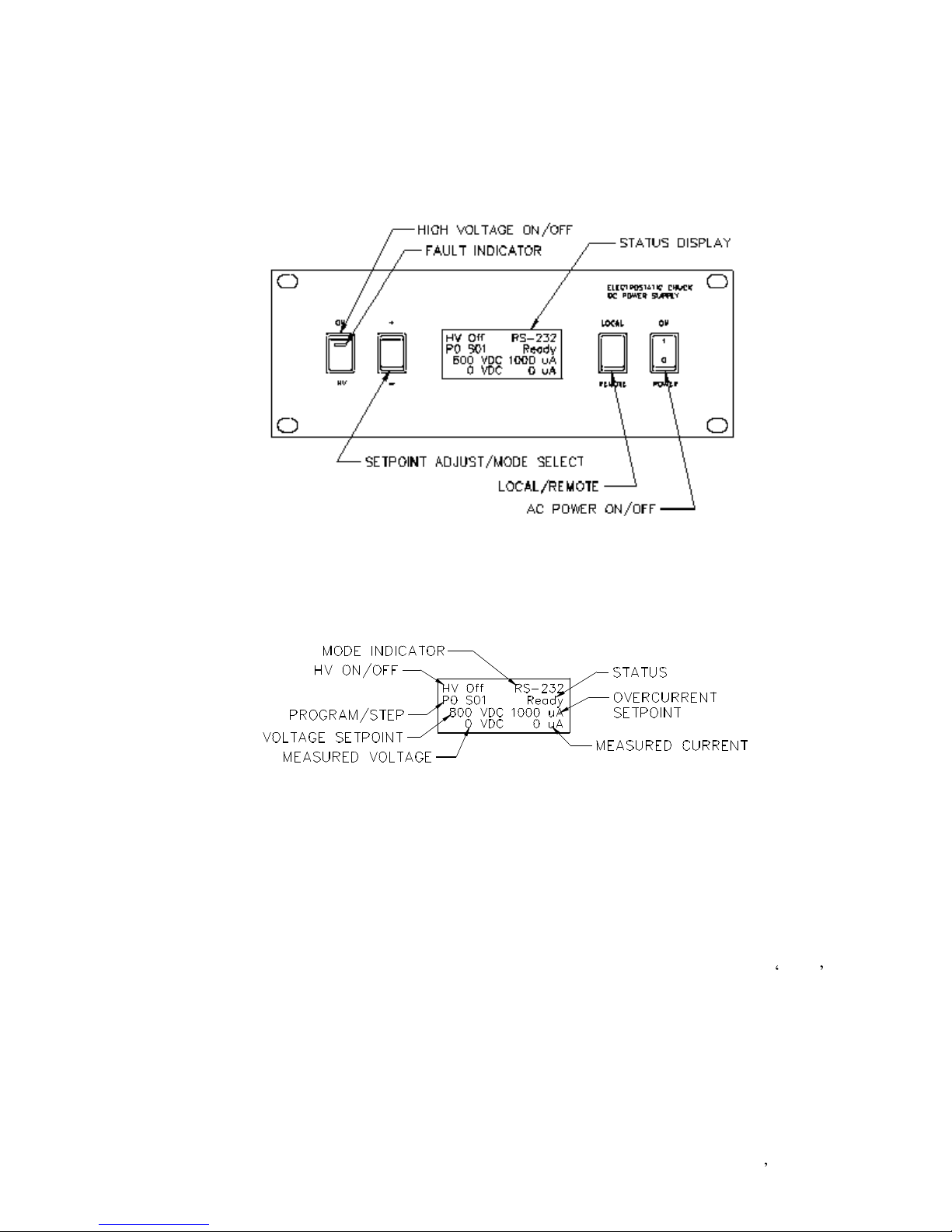
Figure 3
.1 - EPS200 Front Panel
3.2. The Front Panel.
The EPS200 front panel user interface is simple to operate. The
operation of the various switches is explained in the following sections. The four line,
backlit LCD panel provides program and status information.
Figure 3.2 - LCD Status Display
3.3. Setting the Operating Mode. The EPS200 has a local operating mode and four
remote operating modes. The local mode can be used for testing and developing new
programs. The remote mode, which disables the
front panel setpoint adjustment, is
normally used in a production process where repeatability and automated processing is
desired.
3.4. Local Operating Mode. The local mode is entered by setting the LOCAL/REMOTE
switch on the front panel to the LOCAL positi
on. The mode indicator will display Local
when the unit is in local mode.
If the HV ON switch is in the ON position, when the mode is set to local, the HV ON fault
indicator will blink. The fault will not clear until the switch is set to the off posit
ion. When
the HV ON switch is depressed, and all pending faults have been cleared, the power supply
executes the currently active program, without a remote control interface required.
Page 9

Gripping Power, Inc
9 EPS200 User s Manual
The high voltage output voltage setpoint can be changed via the setpoi
nt adjust switch on
the front panel. Changes made to the high voltage setpoint in the local mode will alter the
remote mode high voltage setpoint as well. No provision is provided in the local mode to
adjust the overcurrent trip point, or change the acti
ve program. All other parameters must
be adjusted via the RS-232 remote mode.
3.5. Digital Remote Mode.
The digital remote operating mode is entered by setting the
LOCAL/REMOTE switch on the front panel to the REMOTE position. Press the mode
select switch
until 'DigRem' is displayed in the mode indicator area of the status display.
Note that the HV ON switch is ignored when in digital remote mode.
The default output voltage used during the HV ON cycle is displayed and may not be
changed while in this oper
ating mode. The HV ON command is given in this mode via the
15-pin control connector in the rear of the unit. Refer to Appendix D for digital remote
mode interface information.
When the HV ON signal is activated, the power supply executes the currently
selected
program. As with any other program, the execution of the program may change the output
voltage from the stored value. If the previously stored high voltage setting is desired, the
selected program should not contain a SV commands, which will alter
the stored output
voltage setpoint.
3.6. Analog Remote Mode. The analog remote operating mode is entered by setting the
LOCAL/REMOTE switch on the front panel to the REMOTE position. Press the mode
select switch until 'AlgRem' is displayed in the mode ind
icator area of the status display.
Note that the HV ON switch is ignored when in analog remote mode.
The high voltage output setpoint used during the HV ON cycle is obtained from the 15-pin
control connector, on the rear of the unit. The analog voltage
is converted to a setpoint and
displayed on the status display. The high voltage output will not track the analog input.
The analog input is sampled only when the HV ON command is given. The HV ON
command is given in this mode via the 15-pin control conn
ector in the rear of the unit via
the digital remote interface. Refer to Appendix D for interface information.
When the HV ON signal is activated, the power supply executes the currently selected
program. As with any other program, the execution of the
program may change the output
voltage from the stored value. If the exclusive use of the analog input voltage setting is
desired, the selected program should not contain a SV commands, which will alter the stored
output voltage setpoint.
3.7. RS-232 Remote Mod
e.
The RS-232 remote operating mode is entered by setting the
LOCAL/REMOTE switch on the front panel to the REMOTE position. Press the mode
select switch until 'RS
-232 is displayed in the mode indicator area of the status display.
Note that the HV ON s
witch is ignored when in RS-232 remote mode.
T
he host computer must be capable of supporting a 9600 baud DTE RS-232 device and have
the proper software installed, to communicate with the EPS200 via the RS-232 serial port.
Refer to Appendix C for RS-232 i
nterface specifications.
A versatile command protocol has been developed for the EPS200 with the intent to make it a
flexible production or development instrument designed to fit any need. Refer to sections four
Page 10

Gripping Power, Inc
10
EPS200 User s Manual
and five for additional information on the
EPS200 command set and program development.
There are two immediate command formats used with the EPS200.
Immediate mode command only format:
> a [sp] cc [cr]
Immediate mode command with parameters format:
> a [sp] cc [sp] dddd [cr]
All messages sent to
the EPS200 must start with an ASCII '>' (hex 3E) or the following fields
will be ignored. The following one byte code [a] is the unique address of the target unit. This
code is a hex-ASCII value ranging from 0-9 and A-F. The EPS200 currently only suppor
ts
address zero (hex 32).
ASCII space characters [sp] (hex 32) act as delimiters and must be inserted as shown between
fields. No space is permitted after the attention character and the address field. The following
field [cc] is the command field, whic
h contains a two byte ASCII character from the EPS200
instruction set.
The data field, if it is used, may contain up to four ASCII bytes. For example, if the desired
target voltage is 850 volts, then an ASCII '850' should be in the data field.
After t
he complete message has been sent, a carriage return (hex 0D) must be sent to unit to
indicate the end of the message. If the last byte after the command message is not a carriage
return, of the command does not pass syntax checks, the data will be ignore
d and a ?
character will be returned. Multiple commands per line are not allowed.
Except where indicated, the EPS200 buffers the incoming data, tests for a valid command,
executes or stores it. The acknowledge message will be returned to the host only
after the
command has been processed. The unit will not respond to further polls until the previously
received command has been processed and acknowledged.
3.8. RS-232 Command Lockout.
If the EPS200 is running a program the unit will only
respond to a subs
et of commands, which provide limited control and status information only.
This feature prevents conflicting or improper settings from being received by the unit.
AB
Abort the current program
MV
Measure volts at terminals
MI
Measure current at terminals
OF
High voltage off/stop program
R1
Read timer 1 (user time delay)
R2
Read timer 2 (HV on time)
R3
Read timer 3 (OEM odometer)
RC
Return compliance value
RI
Return overcurrent trip point
RM
Report maximum voltage
RP
Return program number/step/run-stop
RS
Return hardware status
RV
Return voltage setpoint
??
HELP command
Table 3.1 - Valid RS-232 Commands When a Program is Executing
Page 11

Gripping Power, Inc
11
EPS200 User s Manual
Even when the EPS200 is in local mode, the host computer can still poll the unit via RS-232 to
determine
why the unit is not responding to configuration changes by decoding the status byte
(RS command). The host computer can prompt a user to toggle the front panel mode switch to
the remote position, so that processing can continue. The AB and OF commands ar
e included
as a remote safety feature.
AB
Abort the current program
OF
High voltage off
RP
Return program status
RS
Return hardware status
Table 3.2 - Valid RS-232 Commands in Local Mode
3.9. DeviceNet Mode.
The DeviceNet remote operat
ing mode is entered by setting the
LOCAL/REMOTE switch on the front panel to the REMOTE position. Press the mode
select switch until 'DevNet' is shown in the mode display. The EPS200 currently does not
support DeviceNet and will ignore all commands until
it is returned to one of the other three
operating modes.
Page 12

Gripping Power, Inc
12
EPS200 User s Manual
4. PROGRAM AND CONTROL COMMANDS
4.1. Introduction.
The command set of the EPS200 has been designed to provide the user
with outstanding process flexibility. In addition to basic on and off commands, th
ere are a
wide range of reporting, configuration, and control commands. All EPS200 commands,
except SO, WF and WT can be used in immediate mode, as shown in the examples. Refer
to section five for additional information on program specific commands.
In
all modes, other than the RS-232 remote mode, all serial commands will be ignored,
except for AB, OF, RS and RP. Unless otherwise indicated, most commands do not require
numerical parameters. When entering numerical parameters, leading zeros, or fixed le
ngth
fielding is not required. Current and voltage units are reported in volts and microamps.
4.2. High voltage control commands. The following commands control, and adjust
parameters related to, the high voltage output.
4.2.1. (CF) Set high voltage compliance off. If the user expects the load to change
significantly, such as during thermal stabilization, the EPS200 can be set to ignore
compliance faults completely by sending a CF command.
Send:
>0 CF [CR]
Receive:
>0 CF [CR]
4.2.2. (CN) Set high voltage compliance
on.
Once the load had stabilized and voltage
tracking errors are significant, a CN command will turn the voltage compliance error
detection on. Voltage compliance deviations outside the compliance widow will
produce an overload fault.
Send:
>0 CN [CR]
Receive:
>0 CN [CR]
4.2.3. (OF) High voltage output off.
If an OF command is received, when a program
is not executing, the high voltage output is immediately turned off. If a program is
running, and a WF instruction was active, the program will continue nor
mal execution.
Send:
>0 OF [CR]
Receive:
>0 OF [CR]
4.2.4. (ON) High voltage output on.
If an ON command is received and a program is
not executing, the high voltage output is immediately turned on. The output will
remain on until another command is receiv
ed that can override the high voltage on
condition. If a program is running, the ON command will be ignored.
Send:
>0 ON [CR]
Receive:
>0 ON [CR]
4.2.5. (SB) Set output to default value.
During a program run, the SO value can
temporarily change the high vol
tage output from the stored setpoint value. The high
voltage output can be reset back to the stored setpoint by executing a SB command
.
Send:
>0 SB [CR]
Receive:
>0 SB [CR]
Page 13

Gripping Power, Inc
13
EPS200 User s Manual
4.2.6. (SC) Set high voltage compliance window.
Once the high voltage is on, the
u
nit will attempt to adjust the output voltage to compensate for varying load conditions.
If the high voltage output deviates outside of the compliance window, an overload error
will be produced. The compliance window can be up to 99 VDC. Valid parameter
s are
0 up to 99.
Send:
>0 SC 10 [CR]
Receive:
>0 SC 10 [CR]
4.2.7. (SV) Set high voltage setpoint.
The SV command sets the value of the high
voltage output used whenever the ON command is issued directly or within a program
in RS-232, digital remote, local or DeviceNet modes. This value is ignored in analog
remote mode. Valid parameters are 0 up to 1000 for a 1kV unit and 2500 for a 2.5kV
unit.
Send:
>0 SV 900 [CR]
Receive:
>0 SV 900 [CR]
4.2.8. (SI) Set overcurrent trip point.
The SI command sets the value
of the
overcurrent trip point used in all operating modes. The EPS200 will turn off the high
voltage output when the overcurrent trip point is reached. When this occurs, the alarm
output is set and the unit displays an 'Overload' message. The alarm conditi
on can be
cleared by any user acknowledge, such as a status poll or a toggling of the
REMOTE/LOCAL switch. Valid parameters are 0 up to 1000 microamps.
Send:
>0 SI 500 [CR]
Receive:
>0 SI 500 [CR]
4.2.9. (RM) Report maximum voltage.
The RM command is used t
o indicate the
maximum full scale range of the EPS200. All units have a 0 to 1000 VDC or 0 to 2500
VDC range.
Send:
>0 RM [CR]
Receive:
>0 1000 [CR]
4.2.10. (SH) Shunt HV output.
The SH command will cause the power supply to
short the output terminals throug
h the internal output resistor network. This command
can be beneficial in removing residual charges left on the chuck before or after
processing.
Send:
>0 SH [CR]
Receive:
>0 SH [CR]
4.2.11. (TP) Toggle polarity.
The TP command causes the output voltage polar
ity to
reverse. If the high voltage is on, the output will turn off and then back on at the
reverse polarity. If the high voltage is not on, the polarity will reverse with the next
HV ON command. The value of the setpoint voltage does not change. Rever
sing the
chuck voltage polarity is typically performed to remove charge from the chuck surface
when dechucking substrates.
Send:
>0 TP [CR]
Receive:
>0 TP [CR]
Page 14

Gripping Power, Inc
14
EPS200 User s Manual
4.2.12. (PP) Set polarity positive.
The PP command causes the output voltage
polarity to be set t
o positive. If the high voltage is on and at the opposite polarity, the
output will turn off and then turn back at the assigned polarity. If the high voltage is
not on, the set polarity command will take effect with the next HV ON command. The
value of
the setpoint voltage does not change.
Send:
>0 PP [CR]
Receive:
>0 PP [CR]
4.2.13. (NP) Set polarity negative.
The NP command causes the output voltage
polarity to be set to negative. If the high voltage is on and at the opposite polarity, the
output will t
urn off and then turn back at the assigned polarity. If the high voltage is
not on, the set polarity command will take effect with the next HV ON command. The
value of the setpoint voltage does not change.
Send:
>0 NP [CR]
Receive:
>0 NP [CR]
4.3. Status
information commands.
The following commands provide status information
about the unit, operating parameters or program condition.
4.3.1. (ID) Return software version.
The ID command returns the software version
installed in the EPS200.
Send:
>0 ID [CR]
Receive:
>0 EPS200 01.30 [CR]
4.3.2. (RS) Return Status.
The RS command will return a four byte ASCII
hexadecimal value which can be decoded to determine the status of the unit. This
command is valid in all operating modes, including local mode.
Send:
>0 RS [CR]
Receive:
>0 dddd [CR]
The dddd is an ASCII hexadecimal value. Each bit represents an operating mode or
condition of the unit. Bits D11 to D15 are not used and are fixed at a value of 0 .
D10
Voltage compliance mode (active/inactive)
D9
Overcur
rent/overload fault
D8
Voltage compliance fault
D7
EPS200 mode bit (see table 4.2)
D6
EPS200 mode bit (see table 4.2)
D5
Local/Remote switch position
D4
HV is on
D3
Output polarity
D2
Program stop/run
D1
CLAMP IS DOWN bit is on
D0
CLAMP IS UP bi
t is on
Table 4.1 - 16 bit Status Data Bit Description
The EPS200 operating mode can be determined by decoding bits 6 and 7.
Page 15

Gripping Power, Inc
15
EPS200 User s Manual
D7
D6
0
0
RS-232 interface
1
0
Digital remote interface
0
1
Analog remote interface
1
1
DeviceNet i
nterface
Table 4.2 - EPS200 Mode Bits in the Status Value
The Local/Remote switch bit (D5) will be set when the front panel switch is in the
remote position and cleared when the switch is in the local position. The program
run/stop bit (D2) w
ill be set when a program is running and the bit will be cleared when
a program is aborted or has completed.
The polarity bit (D3) is cleared when the power supply output is in a positive polarity
mode and the bit will be set when the power supply output
is in a negative polarity
mode, whether high voltage is actually present or not. The polarity bit will be static
until a PP, NP or TP command is received.
The remaining bits are set when the indicated condition is active and reset when they
are inactiv
e.
4.3.3. (RP) Return program status.
The RP command returns the number of the
selected program, the program step number that is currently executing (if any), and the
activity of the program (running or stopped).
Send:
>0 RP [CR]
Receive:
>0 P0 01 S [CR]
In
this example, the selected program is program zero (P0), the current step is step one
(01) and the program is stopped (S). If a program is running, the last character will be
a (R).
4.3.4. (MI) Measure current at terminals.
The MI command returns the measure
d
value of the EPS200 output current. The value is expressed in microamps. The sign
will be positive (+) or negative (-).
Send:
>0 MI [CR]
Receive:
>0 -250 [CR]
4.3.5. (MV) Measure volts at terminals.
The MV command returns the measured
value of the volta
ge at the EPS200 output terminals. The voltage value is expressed in
volts. The sign will be positive (+) or negative (-).
Send:
>0 MV [CR]
Receive:
>0 +750 [CR]
4.3.6. (RC) Return compliance value.
The RC command returns the value of the
voltage compliance
window, in volts, as set by the SC command.
Send:
>0 MV [CR]
Receive:
>0 10 [CR]
Page 16

Gripping Power, Inc
16
EPS200 User s Manual
4.3.7. (RI) Return overcurrent trip point.
The RI command returns the setting of the
overcurrent trip value, in uA, as set by the SI command.
Send:
>0 RI [CR]
Receive:
>0 500 [CR]
4.3.8. (RV) Return voltage setpoint.
The RV commands returns the current value of
the stored high voltage setpoint used in all of the operating modes. This value is set by
the SV command.
Send:
>0 RV [CR]
Receive:
>0 900 [CR]
4.4. T1, T2 and T3 timer comm
ands.
The timer commands allow the user to reset, load,
start and display the timer data. The EPS200 has three process timers: one general purpose
and two high-voltage activity monitors.
Timer 1 (T1) is a user programmable timer that can be used as a
countdown timer, when
used in conjunction with the WT command. The resolution of T1 is one second. It has a
maximum time period of 59 minutes and 59 seconds.
Timer 2 (T2) tracks the period the high voltage has been on, since timer 2 was last cleared,
u
sing the C2 command. Timer 2 can be used as a chuck or chamber preventative
maintenance timer. The resolution of T2 is one second. It has a maximum time period of
59,999 hours, 59 minutes and 59 seconds.
Timer 3 (T3) is the OEM high voltage on timer. T
his timer cannot be reset and is used by
the manufacturer for MTBF information. The resolution of T3 is one minute. It has a
maximum time period of 59,999 hours and 59 minutes.
4.4.1. (C1) Clear timer 1.
The C1 command resets the T1 general purpose timer to
00
:00 and stops it.
Send:
>0 C1 [CR]
Receive:
>0 C1 [CR]
4.4.2. (ST) Set timer 1.
The ST command loads the user defined time-out value into
timer 1 and starts the timer. The minutes and seconds entry may be entered as seconds
alone.
Send:
>0 ST mmss [CR]
Receive:
>0 ST mmss [CR]
4.4.3. (RT) Reload and start timer 1.
The RT command reloads T1 with the value
previously specified by the ST command and restarts the timer.
Send:
>0 RT [CR]
Receive:
>0 RT [CR]
4.4.4. (R1) Read timer 1.
The R1 command returns the time
remaining on the T1
timer.
Send:
>0 R1 [CR]
Receive:
>0 12m 34s [CR]
Page 17

Gripping Power, Inc
17
EPS200 User s Manual
4.4.5. (C2) Clear timer 2.
This command resets the T2 timer to 00:00. If timer 2
is reset with the high voltage in the on state, the timer will reset and continue timing
until the high v
oltage is turned off.
Send:
>0 C2 [CR]
Receive:
>0 C2 [CR]
4.4.6. (R2) Read timer 2.
The R2 command returns the time that the high voltage has
been on, since the prior reset of the T2 timer. This time can be used as a chuck or
chamber preventative maintenan
ce indicator.
Send:
>0 R2 [CR]
Receive:
>0 5h 49m 24s [CR]
4.4.7. (R3) Read timer 3. The R3 command returns the contents of the OEM
cumulative high voltage on period timer. This timer may not be reset by the user.
Send:
>0 R3 [CR]
Receive:
>0 345h 23m [CR]
4.5. Digital output control.
The EPS200 provides the user with three digital output bits.
Two of those bits are available to the user for emulating mechanical clamp interfaces. The
bits are identified as clamp is up and clamp is down.
When a clam
ping/chuck operation is started, clamp is up is normally cleared and clamp
is down is set active. When the chucking operation is completed, clamp is up is
normally set and clamp is down is cleared. The user must set the bits to the preferred state
throughout a program.
If an abort (AB) command is received, or a fault is cleared, the EPS200 will automatically
reset the bits to the default state of clamp is up set and clamp is down cleared.
4.5.1.
(CD) Clear the clamp is down bit.
The CD command
sets the clamp is
down output bit off. The clamp is down output is an open-
collector output and will
be left floating when the bit is in the off condition
Send:
>0 CD [CR]
Receive:
>0 CD [CR]
4.5.2.
(CU) Clear the clamp is up bit.
The CU command sets
the clamp is up
output bit off. The clamp is up output is an open-
collector output and will be
left floating when the bit is in the off condition.
Send:
>0 CU [CR]
Receive:
>0 CU [CR]
4.5.3.
(SD) Set the clamp is down bit. The SD command sets the clamp is down
output bit on. The clamp is down output is an open-
collector output and will be
driven low, to digital common, when the bit is in the on condition.
Send:
>0 SD [CR]
Receive:
>0 SD [CR]
Page 18

Gripping Power, Inc
18
EPS200 User s Manual
4.5.4.
(SU) Set the clamp is up bit.
The SU command se
ts the clamp is up output
bit on. The clamp is up output is an open-
collector output and will be driven low, to
digital common, when the bit is in the on condition.
Send:
>0 SU [CR]
Receive:
>0 SU [CR]
Page 19

Gripping Power, Inc
19
EPS200 User s Manual
5. PROGRAMMING
5.1. Introduction.
One of the unique
features of the EPS200 is its ability to allow the user
to develop complex chucking algorithms using a proprietary command language. The unit
can store up to ten programs that control the chucking and dechucking operation. Each
program can be up to 32 s
teps long. The unit may be directed to execute any one of the ten
stored programs, giving the user maximum flexibility in both the setup phase, when testing
chuck reliability, and in production operation. All ten of the EPS200 programs are stored in
nonv
olatile RAM and can be downloaded to a host computer. The EPS200 programming
command set provides the user optimum flexibility for developing sophisticated chucking
algorithms for multiple process conditions.
5.2. Program specific commands.
In addition to th
e general purpose commands detailed
in section 4, there are additional commands that that can only be used within programs or
are related to program control.
5.3. Special program commands.
These commands that have unique functions and are
related to program f
low or have other special functions. These commands can only be used
from within a program.
5.3.1. (WF) Wait for HV off.
This command will cause a program to pause execution
and wait for an high voltage off condition or command. If a high voltage off
condit
ion is already present when the WF instruction is encountered, program
execution will continue with the next instruction
Instruction Format: WF[CR]
In local mode, once a program has been started by pressing the high voltage switch and
a WF is encountered
, the EPS200 will wait for the switch to be set to the off position.
In digital or analog remote mode, once a program has been started by setting the high
voltage go on bit and a WF is encountered, the EPS200 will wait for the high voltage
go on bit to
be reset.
In RS-232 remote mode, once a program has been started by sending a XP command,
and a WF is encountered, the EPS200 will wait for an OF command. Note that
changing from remote mode to local mode, while a program is executing, will have the
sa
me affect as an AB command.
5.3.2. (WT) Wait for timer 1.
This command causes a program to pause until timer
one expires. No arguments are required.
Instruction Format: WT[CR]
Before the WT command can be used, the program interpreter must have encountered a
RT or ST command. The RT or ST command will load and start the timer. When the
program interpreter encounters the WT instruction, program execution will stop until
the timer one count reaches 00:00.
5.3.3. (SO) Set high voltage output level.
The SO command s
ets the high voltage
output level from within a program. The SO command does not alter the setpoint value
stored in memory, which is set with the SV command. Valid parameters are 0 up to
1000 for a 1kV unit and 2500 for a 2.5kV unit.
Instruction Format: SO 825 [CR]
Page 20

Gripping Power, Inc
20
EPS200 User s Manual
Once a program has terminated, any ON command will produce an output voltage that
corresponds to the most recent SV command setting. The SO command is useful to
develop sophisticated dechucking waveforms without affecting the setpoint for
chu
cking.
5.4. Program control commands.
The following commands provide the user the ability to
execute, abort, list and clear programs. Once the EPS200 has begun program execution,
only the AB program control command will be accepted, all others will be ignored.
5.4.1. (AB) Abort the current program.
The AB command stops the operation of the
current program, turns off the high voltage, resets the digital outputs, returns to
program step 01 and if possible, returns to the ready state.
Send:
>0 AB [CR]
Receive:
>
0 AB [CR]
5.4.2. (CP) Clear current program. The CP command erases all steps of the current
program. Be cautious in the use of this command. No prompt is provided. Only the
currently selected program, as indicated on the status display, is erased.
Send:
>
0 CP [CR]
Receive:
>0 CP [CR]
5.4.3. (CA) Clears all programs.
The CA command clears all ten of the EPS200
stored programs. The user is prompted for a Y(es) or N(o) response to confirm that
erasure of all of the stored programs is desired.
Send:
>0 CA [CR]
Receive: Preparing to clear ALL programs. [CR]
Are you sure (Y-N)? [CR]
5.4.4. (LP) List current program.
The LP command sends a listing of the currently
selected program to the serial port. The output format includes line numbers so that it
may be uploade
d into another EPS200. A simple program is shown for example.
Send:
>0 LP [CR]
Receive:
P0 [CR]
01 SV 850 [CR]
02 ON [CR]
03 WF [CR]
5.4.5. (Pn) Select program.
The EPS200 supports up to 10 user defined programs,
stored as P0 through P9. To select
a program, enter the desired program number
immediately after the select program mnemonic. All operating modes use the same
programs and all program locations (P0-P9) are identical in function. The last program
selected remains in effect for all modes un
it another select program command is
processed.
Send:
>0 P3 [CR]
Receive:
>0 P3 [CR]
5.4.6. (XP) Execute current program.
The XP command causes the currently
selected program to begin execution. The return message indicates that the program
Page 21

Gripping Power, Inc
21
EPS200 User s Manual
selected was
executed. If a fault condition is active, a ? will be returned and the
program will not run until the fault has been cleared.
Send:
>0 XP [CR]
Receive:
>0 XP P0 [CR]
5.4.7. (??) Help. A brief listing of all available EPS200 commands can be displayed
by
sending the unit the help listing command.
Send:
>0 ?? [CR]
Entering program commands.
User programs may be up to 32 steps long. Each program
instruction is entered similar to the immediate mode commands, with the exception that a
line number is inclu
ded with the instruction. The instructions are stored and executed in
sequence, based upon the instruction line number.
There are two program instruction formats
used with the EPS200.
Program instruction only format:
> a [sp] nn [sp] cc [cr]
Program i
nstruction with parameters format:
> a [sp] nn [sp] cc [sp] dddd [cr]
All program instructions sent to the EPS200 must start with an ASCII '>' (hex 3E) or the
following fields will be ignored. The following one byte code [a] is the unique address of the
target unit. This code is a hex-ASCII value ranging from 0-9 and A-F. The EPS200 currently
only supports address zero (hex 32).
ASCII space characters [sp] act as delimiters and must be inserted as shown between fields.
No space is permitted after the
attention character and the address field.
The following field [nn] is the line number, which can range from 01 to 32. Instruction lines
can be entered in any order. Instructions are stored and listed in order, sorted by line number.
Line numbers ma
y be skipped. Empty program locations are treated as no operation and are
skipped.
The next field [cc] is the instruction field, which contains a two byte ASCII character from the
EPS200 instruction set. The program instruction can be any instruction
that is valid within a
program. Some instructions are not valid in programs. Refer to Table 5.1 and section four for
additional information.
The data field [dddd] may contain up to four ASCII bytes. For example, if the desired target
voltage is 850 vol
ts, then an ASCII '850' should be in the data field. Leading zero are not
required.
After the complete message has been sent, a carriage return (hex 0D) must be sent to unit to
indicate the end of the message. If the last byte after the command message
is not a carriage
return or the command does not pass syntax checks, the data will be ignored and a ?
character will be returned.
Multiple program instructions per line number are not allowed.
Page 22

Gripping Power, Inc
22
EPS200 User s Manual
MV Measure volts at terminals (+/
-)
MI
Measure current
at terminals (+/
-)
R1
Read timer 1 (user time delay)
R2
Read timer 2 (HV on time)
R3
Read timer 3 (OEM odometer)
RC
Return compliance value (V)
RI
Return overcurrent trip point (I)
RM Report maximum voltage
RP
Return program number/step/run-stop
RS
Return hardware status
RV
Return voltage setpoint (V)
??
Help command
Table 5.1 - Instructions that may not be used in a program
Page 23
Gripping Power, Inc
23
EPS200 User s Manual
6. TROUBLESHOOTING
6.1. Introduction.
This section provides the user with information on methods to resolve
problems that m
ay be encountered in the event the EPS200 is not functioning properly.
To determine the fault condition, refer to the LCD display. It provides information to
determine whether the unit is functioning properly.
6.2. Overload Fault.
An overload fault can be
caused by an overcurrent trip point setting
that is too low, an output voltage setpoint is beyond the capability of the EPS200, for
the given load, or an electrical problem with the load.
The output overcurrent limit setpoint can be adjusted with a SI co
mmand. Increase the
setting, up to 1000 uA, and restart the unit. If the load current exceeds the over current
trip point, the unit will shut off the high voltage output, or abort a running program.
This allows the user to set a lower limit for the expe
cted load impedance.
If voltage compliance monitoring is activated and voltage compliance cannot be
maintained, the unit will produce an overload fault,. Correct the problem by turning
off voltage compliance monitoring (CN command), reset the voltage set
point to a lower
value (SV command) or inspect the load for shorts or other excessive loading.
If the unit continues to display the overload fault, disconnect the unit from the load and
turn on the high voltage. If the high voltage comes on and achieves
the desired voltage
level, the unit is performing normally.
If the unit continues to display the Overload
message when isolated from the load, it has experienced an internal failure and must be
returned for factory repair.
6.3. Alarm Output.
The alarm
output is set whenever an overload fault occurs. The alarm
output can be cleared by any user acknowledge, such as a status poll or a toggling of
the REMOTE/LOCAL switch.
6.4. No Output.
If the EPS200 does not produce a high voltage output, verify that the unit
is properly powered and that the LCD display indicates a ready state. If the unit could
not achieve voltage compliance, or a overload condition exists, an 'Overload' message
will be displayed. If the unit has detected an internal fault, it will produc
e a coded error
message.
6.5. Component replacement.
There are no user serviceable components in the any of the
EPS series power supplies. Any EPS unit should be returned to the factory for repair
or replacement.
WARNING:
Dangerous high-voltages are presen
t inside the
EPS200. Under no circumstances should the user attempt to
remove the cover or repair or adjust the internal circuitry.
Page 24

Gripping Power, Inc
24
EPS200 User s Manual
APPENDIX A - Programming Examples
The following program emulates basic electrostatic chuck p
ower supply functions of chucking
and dechucking. The program will set the high voltage setpoint to 800 VDC, wait for the high
voltage go off command and then apply a reverse pulse of 800 VDC for two seconds to
discharge the chuck and release the substrat
e.
01 TP
; toggle the polarity
02 SV 800
; set the output to 800 VDC
03 ON
; turn on the high voltage
04 WF
; wait for the high voltage off command
05 TP
; toggle polarity
06 ON
; turn on the high voltage
07 ST 4
; start a four second timer
08 WT
; wait for the timer to expire
09 OF
; turn off the high voltage
This program better illustrates the flexibility of the EPS200. An oscillating voltage can be
produced by the EPS200 to discharge the chuck, and more effectively release the substrate.
Digital output bit commands are included as well.
01 TP
; toggle polarity
02 SV 800
; set the output to 800 VDC
03 CU
; clear clamp is up bit
04 SD
; set clamp is down bit
05 ON
; turn on the high voltage
06 WF
; wait for the high voltage off command
07 TP
; toggle polarity
08 ON
; turn on the high voltage
09 SV 800
; set output to 800V
10 ST 8
; start eight second timer
11 WT
; wait for timer to expire
12 TP
; toggle polarity
13 ON
; turn on the high voltage
14 SV 400
; set output to 400V
15 ST 6
; start six second timer
16 WT
; wait for timer to expire
17 TP
; toggle polarity
18 ON
; turn on the high voltage
19 SV 200
; set output to 200V
20 ST 4
; start four second timer
21 WT
; wait for timer to expire
22 0F
; turn high voltage off
23 SU
; set clamp is up bit
24 CD
; clear clamp is down bit
These programs are shown for example only. Some electrostatic chuck algorithms have been
patented. Use of patented algorithms may be a violation of federal law.
Page 25

Gripping Power, Inc
25
EPS200 User s Manual
APPENDIX B - Technical Specifications
AC Pow
er Requirements
Input power required:
95 - 265 VAC, 47 - 63 Hz, 40 watts
Input power connection:
IEC 320, female
Environmental
Storage temperature range:
0F -
140
F
Operation temperature range:
40F -
120
F
Humidity:
10 - 90%, non-condensing
Physical
D
imensions (H x W x D)
3.5" x 9.5" (front panel) x 10"
Weight
3 lb. (1.3 kgs)
DC Output
EPS200-1
0 to 1,000 VDC,
1%
EPS200-2
0 to 2,500 VDC,
1%
Output impedance
150 kohm
Output connector
BNC (2x)
High voltage output isolation from chassis
100 meg mi
nimum
Operating Modes and Interface Options
Operating modes
1 local, and 3 remote
Remote control interfaces
Digital, analog, RS-232
Program Specifications
Number of user defined programs
10
Number of steps per program
32
Testing Agency Approvals
The int
ernal line-powered, low-voltage DC switching power supply and the IEC power entry
module meet UL, CSA, TUV and CE requirements.
Page 26

Gripping Power, Inc
26
EPS200 User s Manual
APPENDIX C - RS-232 Connector Specifications
The RS-232 serial interface connector is a female, 9 pin, D-subminiature style co
nnector,
located on the rear panel.
Figure C.1 - Serial Interface Connector
Pin
Description
Direction
2
Transmit Data
Output
3
Receive Data
Input
5
Common
All serial communicati
ons meets RS-232C requirements. The baud rate is fixed at 9600 baud.
No parity and one stop bit is required. Modem control lines, such as RTS and CTS, are not
provided. No handshaking protocol (such as XON and XOFF) is supported. The host system
must
delay data transmission to avoid overflowing the EPS200 serial buffer.
Page 27

Gripping Power, Inc
27
EPS200 User s Manual
APPENDIX D - Remote Control Interface Specifications
The analog and digital remote control interface connector is a female,
15 pin, D-subminiature style connector, located on the rear
panel.
Figure D.1 - Remote Control Connector
Pin
Description
Direction
1
HV go on (
-)
Input
2
HV analog setpoint (1V = 1000 VDC)
Input
3
HV go on (+)
Input
4
+12 VDC (current limited)
Outpu
t
5
Analog common
Input
6
Measured HV output (
1V =
1000 VDC)
Output
7
Clamp is active (active low to pin 10)
Output
8
Clamp is inactive (active low to pin 10)
Output
9
Alarm output (active low to pin 10)
Output
10
Digital common
Input
11
No connec
tion
12
No connection
13
No connection
14
No connection
15
No connection
Analog I/O pins 2 and 6 are configured for 0-1 VDC operation. Consult the factory for
applications that require a 0-10 VDC interface.
Pins 5 and 10 are not tied together internally
. All digital I/O should be referenced to pin 10 and
all analog I/O should be referenced to pin 5. An external common connection between pins 5
and 10 will not alter the performance of the EPS200.
Pins 1 and 3 are optically isolated from DC power and DC
common. A simple remote control
interface can be accomplished by connecting pins 3 and 4 together and connecting pin 1 to DC
common, via a switch, to set the high voltage go on active via the digital interface.
Page 28

Gripping Power, Inc
28
EPS200 User s Manual
APPENDIX E - Ordering and Service Informat
ion
Before returning defective materials for repair or replacement, contact the manufacture and
obtain an RMA number. All items returned for repair must be packaged properly before
shipment or the warranty will be void.
Ship to: Gripping Power, Inc.
11
930 44th Street North, Suite B
Clearwater, Florida 33762
http://www.GrippingPower.com
Tel: (727) 572-4100
Fax: (727) 592-9894
 Loading...