

GripOne S3 User Manual
GRIPONE S3
Before using GRIPONE read every page of this
manual. The installation of this device requires
attention and accuracy. Please note that you are
installing a device on a vehicle can reach high
speeds. GRIPONE is a professional traction control
system for racing use only. GUBELLINI s.a.s. not be
liable for the consequences resulting from the use of
motorbikes on which it is installed in GRIPONE
system.
Prima di utilizzare il sistema GRIPONE leggere
attentamente tutte le pagine di questo manuale.
L’installazione di questo dispositivo richiede
attenzione. Ricordati che stai installando un
dispositivo su un veicolo in grado di raggiungere
velocità elevate. Il sistema di controllo di trazione
GRIPONE è un dispositivo professionale utilizzabile
nel settore agonistico e non omologato per l’utilizzo
su strada. GUBELLINI s.a.s. non sarà responsabile
delle conseguenze derivate dall’utilizzo dei mezzi su
cui è installato in sistema GRIPONE.

1.0 Included into the kit
1 x ECU
1 x bracket kit (not plug&play)
2 x speed sensor LM8
1 x loom plug&play (with remote buttons)
1 x USB cable
1 x remote led
1 x bracket for remote buttons
1 x user manual
2 x stickers
1.0 Incluso nel kit
1 x ECU
1 x kit staffe (not plug&play)
2 x sensori velocità LM8
1 x cablaggio plug&play (con pulsanti a manubrio)
1 x cavo USB
1 x led remoto
1 x staffa per pulsanti
1 x manuale utente
2 x adesivi
2.0 Security
During the installation of this product, it is
recommended to position the motorbike in such
a way that is cannot cause any injury or damage
by falling down or moving forward or backward;
it is recommended to use the rear stand or, if
necessary, the wheel lock. Make sure that the
injection system is always turned off and that the
electrical equipment is not being powered
during the installation of this product (and, as
well as, during all assembly phases indicated in
this manual). When adding or removing
electrical cables or wiring to/from the
motorcycle’s equipment, always be sure to
remove the negative battery terminal before the
positive battery terminal. During reassembly
phases, connect the negative terminal last in
order to avoid short circuiting the electrical
equipment.
3.0 Installation recommandation
DO NOT RUSH! When installing the GRIPONE
S3, make sure that the unit is protected from
excessive vibrations and surrounding elements
and that it is clamped firmly. When positioning
the wiring, make sure that the wires cannot be
pinched or crushed which may cause subsequent
malfunctions, clamp them as necessary.
2.0 Sicurezza
Durante l’installazione di questo prodotto si
consiglia di collocare la moto in modo che
non possa causare ferite o danni, cadendo o
spostandosi avanti o indietro o lateralmente;
si raccomanda l’utilizzo di un cavalletto
posteriore e se necessario il bloccaggio delle
ruote.
Assicurarsi che l’iniezione sia sempre spenta e
che l'impianto elettrico sia non alimentato
durante l’installazione di questo prodotto (e
comunque durante tutte le fasi di montaggio
indicate da questo manuale). Quando si
rimuovono o aggiungono cavi elettrici o
cablaggi all’impianto del veicolo, rimuovere
sempre il terminale negativo dalla batteria
prima del terminale positivo. In fase di
rimontaggio collegare il terminale negativo
come ultimo per evitare corto circuito
all’impianto elettrico.
3.0 Buone norme per l’installazione
NON AVERE FRETTA! Quando installi
GRIPONE S3 assicurati che l’unità sia protetta
da eccessive vibrazioni, dal calore e dagli
elementi circostanti, e che sia saldamente
fissata. Quando si posizionano i cablaggi
assicurarsi che essi non possano essere
pizzicati o schiacciati e quindi provocare
malfunzionamenti, fissarli con fascette dove
necessario (senza stringere troppo i cavi
incidendoli).

ATTENTION !
The ECU must placed far from high temperature
zone (not more than 65°). The ECU must not be
exposed to vibrations. Locate a surface on which
to secure the unit. Do not secure the unit until it
is finished installing all other components and
wiring.
The use of a traction control system does
not prevent the fall caused by improper
use of the throttle of vehicle. For this
reason it is advisable to test the
functioning of the system GRIPONE S3
through repeated trials and through
small steps. Only after you had the right
confidence and you understood clearly
where and how the device operates on
the engine and chassis, try changing the
settings.
4.0. Introduction to GRIPONE S3
GRIPONE S3 represents the state of art into the
traction control systems for motorcycles. It is a
system "stand-alone" that operate as traction
control, anti wheelie, quick shifter (with the
optional gear shift sensor), pit limiter and launch
control. GRIPONE S3 can be used with or
without the IMU (Inertial Motion Unit). The
inertial platform (IMU), thanks to three
accelerometers is able to understand the
position of the motorcycle, if it is accelerating or
braking, the radius of curvature that the vehicle
is making and much more. The control unit
processes all information and defines a level of
"safe" slip beyond which to limit the power. If
the sliding of rear tyre is too much or the wheelie
is too high, GRIPONE S3 will reduce the power
according to the safe conditions.
ATTENZIONE !
GRIPONE S3 deve essere posizionata dove
non vi sia una temperatura di esercizio
superiore di 65°C e deve essere protetta da
vibrazioni. Localizzare una superficie adatta,
su cui fissare la centralina. Non fissare la
centralina fino a che non è terminata
l’installazione di tutti gli altri componenti e il
cablaggio.
L'utilizzo di un sistema di controllo
trazione non previene la caduta
causata da un utilizzo inappropriato
del comando del gas e/o del veicolo.
Per questo motivo si consiglia di
sperimentare il funzionamento del
sistema GRIPONE S3 attraverso prove
ripetute e attraverso piccoli passi.
Solo dopo aver preso la giusta
confidenza e aver capito con chiarezza
dove e come il dispositivo interviene
sul motore e sulla ciclistica, provare a
modificare le regolazioni.
4.0. Introduzione a GRIPONE S3
GRIPONE S3 rappresenta lo stato dell’arte tra
i controlli di trazione per moto. E’ il primo
sistema “stand-alone” in grado di
implementare il controllo di trazione, l’anti
impennamento, cambio elettronico (con il
sensore opzionale), pit limiter e il controllo
per la partenza. GRIPONE S3 può essere
usata con o senza piattaforma inerziale (IMU).
L’IMU, grazie a tre accelerometri è in grado di
capire l’inclinazione della moto, se questa sta
accelerando o frenando, il raggio di curvatura
che il veicolo sta compiendo e altro ancora.
La centralina elabora tutte le informazioni e
definisce un livello di pattinamento “sicuro”
oltre il quale interviene limitando la potenza.
Se il pattinamento della gomma posteriore è
troppo alto, o l’impennamento è troppo,
GRIPONE S3 ridurrà la potenza in base ai
parametri di sicurezza.
5.0 Electric connection
GRIPONE S3 kit’s include a plug&play loom to
be connected to the main harness of the bike.
No modification are required on the bike.
5.1 Connection of the plug & play loom
The GRIPONE S3 must be connected to the
ignition coils (or fuel injectors for some
application) of all cylinders.
5.0 Collegamenti elettrici
Il kit GRIPONE S3 include il cablaggio
plug&play. Non sono richieste modifiche
all’impianto di serie della moto.
5.1 Connessione del cablaggio
GRIPONE S3 viene collegato alle bobine (o in
alcuni casi agl’iniettori) di tutti i cilindri del
motore.
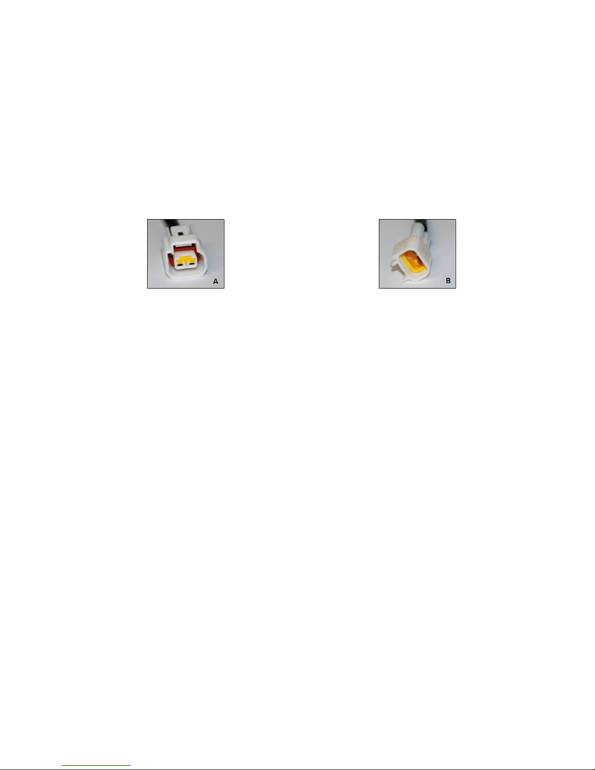
The shape of the connectors may vary according
to the bike. The connector A is an example of
female type. The connector B is an example of
male type
La forma dei connettori può variare in base al
modello di moto. Per ognuno si avranno
sempre un connettore maschio (B) e un
connettore femmina (A).
Follow these steps to connect the loom:
1. Take out the fuel tank (and if necessary the
aribox) to have access to the ignition coils (or the
fuel injectors);
2. Unplug the connector of ignition coil (or
injector) of first cylinder;
3. Connect the female connector (A) of
plug&play harness to the coil (or injector);
4. Connect the male connector (B) of plug&play
harness to the factory connector of main harness
(previously unplugged);
5. Repeat from point 2 to 4 for each cylinders (or
injectors);
6. Connect the black wire of plug&play loom to
the negative pole of battery (or to the chassis or
engine);
7. Lay the plug&play loom by following the
inside of the chassis, to the point where you want
to fix the GRIPONE S3 control unit. The unit can
be placed under the seat or inside the front
fairing. Secure the ECU in a location not too hot
and immune to vibration
8. Connect the unit GRIPONE S3 to the main
Seguire i seguenti passi per il
collegamento:
1. Rimuovere serbatoio e se necessario la
scatola filtro per avere libero accesso alle
bobine (o agli iniettori);
2. Scollegare il connettore dalla bobina (o
dall’iniettore) del primo cilindro;
3. Collegare il connettore femmina (A) del
cablaggio plug&play alla bobina (o
all’iniettore;
4. Connettere il connettore maschio (B) del
cabaggio plug&play al connettore femmina
del cablaggio di serie (precedentemente
scollegato);
5. Ripeter dal punto 2 al punto 4 per tutti gli
altri cilindri;
6. Collegare il filo nero (con il capicorda a
“occhiello”) del cablaggio plug&play a massa
o al negativo della batteria;
7. Stendere il cablaggio plug&play lungo la
parte interna del telaio, fino al punto in cui si
desidera posizionare la centralina GRIPONE
S3;
connector of plug&play loom;
9. Reassemble the airbox and the tank;
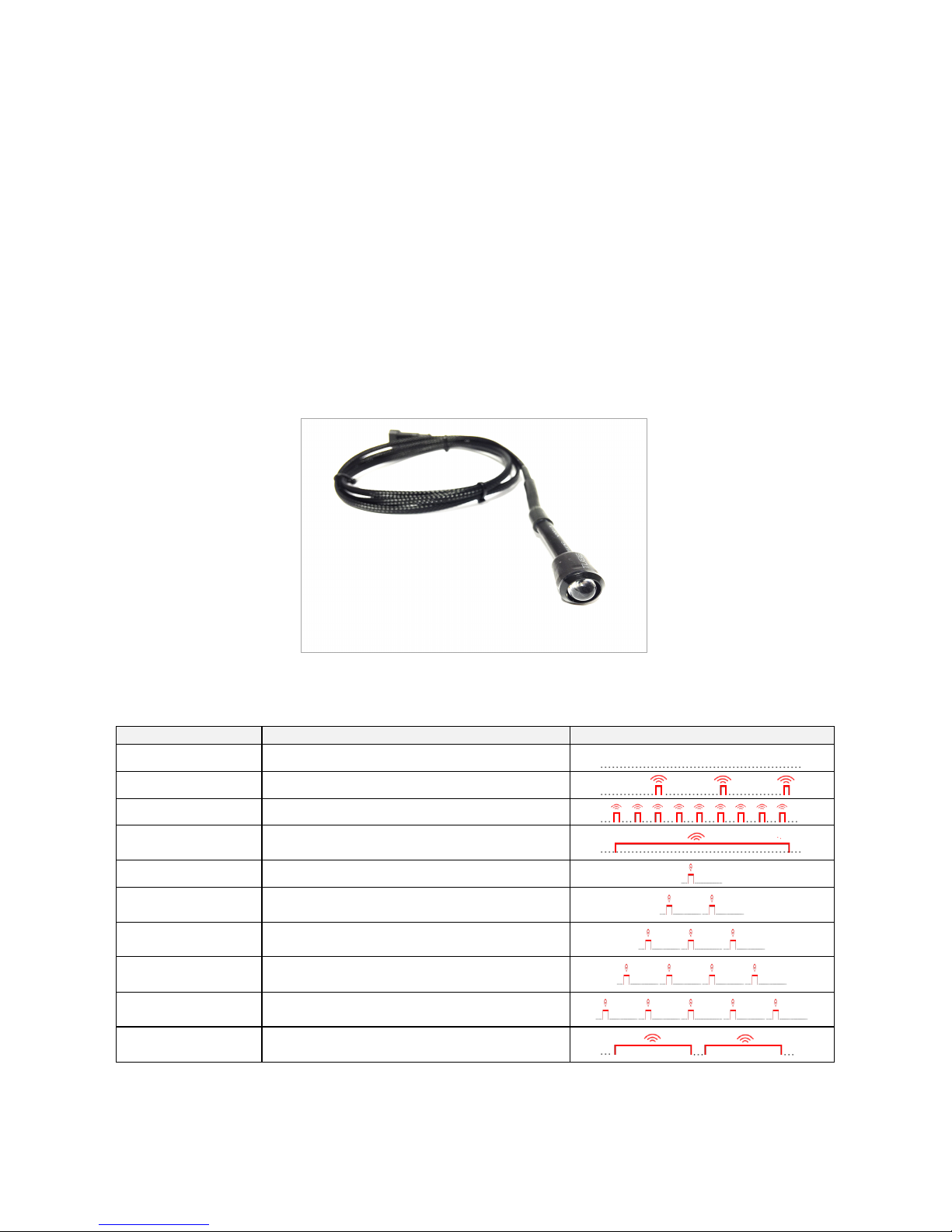
5.3 Connecting the Remote LED
GRIPONE S3 has a remote LED that can be
placed near the dashboard and it is helpful to
check the funtionalities of the unit. Connect the
remote LED to the connector with marker “RE”
of plug&play loom. Place it where you can see it
when you ride the bike.
8. Collegare la centralina GRIPONE S3 al
connettore principale del cablaggio
plug&play;
9. Rimontare la scatola filtro, il serbatoio e la
sella;
5.3 Collegare il Remote LED
GRIPONE S3 è dotato di un LED remoto che
può essere posizionato sul cruscotto ed è
utilizzato per verificare le funzionalità della
centralina. Collegare il LED remoto al
connettore del cablaggio plug&play marcato
“RE”. Posizionalo in un punto visibile.
How it works
Description
Function
Light scheme
Led stay off
ECU is “off mode” or ECU is off.
Short blink (freq. 1Hz)
Stand by mode
Short blink (freq. 5Hz)
Launch control is ready (buti t is not working)
Led stay on
GRIPONE is reducing the power (because traction
control, launch control or anti wheelie are working)
Led show 1 short flash
User select the “TC level” 1 by the remote buttons
Led show 2 short
flashes
User select the “TC level” 2 by the remote buttons
Led show 3 short
flashes
User select the “TC level” 3 by the remote buttons
Led show 4 short
flashes
User select the “TC level” 4 by the remote buttons
Led show 5 short
flashes
User select the “TC level” 5 by the remote buttons
Long blink
One or both speed sensor are broken: the system is
not able to activate TC and AW. Pay attention !!!
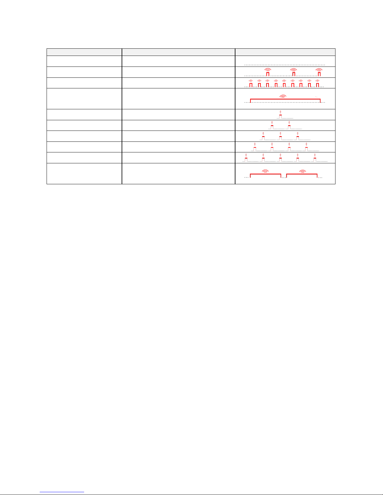
Come funziona il LED remoto:
Descrizione
Funzione
Schema luci
Il led rimane spento
La ECU è in modalità off
Lampeggio (1Hz)
Modo stand by
Lampeggio (5Hz)
Il launch control è pronto
Il led acceso fisso
La ECU stà tagliando potenza (tramite il
controllo di trazione, il controllo della partenza
o l’anti impennamento)
1 lampeggio singolo
Attivata il livello 1 del controllo di trazione
2 lampeggi singoli
Attivata il livello 2 del controllo di trazione
3 lampeggi singoli
Attivata il livello 3 del controllo di trazione
4 lampeggi singoli
Attivata il livello 4 del controllo di trazione
5 lampeggi singoli
Attivata il livello 5 del controllo di trazione
Lampeggio lungo
Uno o entrambi i sensori sono malfunzionanti.
In questa situazione la centralina non è in
grado di attivare i controlli TC e AW.
7.0 Installation of speed sensors
To calculate the speed of the motorcycle,
GRIPONE S3 uses two proximity sensors. The
sensors must be placed so that they detect the
passage of the bolts of the front and rear brake
disk. The kit includes a group of mounting
brackets for the speed sensors. The brackets are
not plug&play, they are a proposal for help the
customer into the installation.
The front bracket must be placed using the
bolts of the fork leg that tighten the wheel
axle’s.
Parts included for the front sensor:
A. Speed sensor
B. Nut M8
C. Nut M8
D. “L” type bracket
E. Spacers for M8 bolts or M6 bolts
Use the spacers if the surface of fork leg is not
flat. Change the bolts with longers if you include
the spacers into the installation
7.0 Installazione dei sensori di velocità
Per calcolare la velocità della moto, GRIPONE
S3 usa due sensori di prossimità. I sensori
devono essere montati in modo in modo che
rilevino il passaggio delle viti di fissaggio del
disco freno anteriore e posteriore. Il kit
include una serie di staffe universali che
possono essere usate sulla maggior parte
delle moto. La staffa anteriore è fissata
utilizzando le viti che stringono il perno ruota
(nel piedino forcella).
Parti incluse per il sensore anteriore:
A. Sensore di velocità
B. Dado M8
C. Dado M8
D. Staffa a “L”
E. Boccole per viti M8 o M6
Utilizzare le boccole se la superficie del
piedino forcella non è spianata. Utilizzare
delle viti più lunghe se s’inseriscono le
boccole.
 Loading...