

GripOne P3 User Manual

www.gripone.com
GRIPONE P3 - ECU
Note
Before using the system GRIPONE read every page of this manual. The installation of this device
requires attention and accuracy. The configuration of the device requires several non-trivial
reflections, referred to only within this manual. Please note that you are installing a device on a
vehicle can reach high speeds. The system GRIPONE is a professional traction control system
approved for use on road.
www.gripone.com
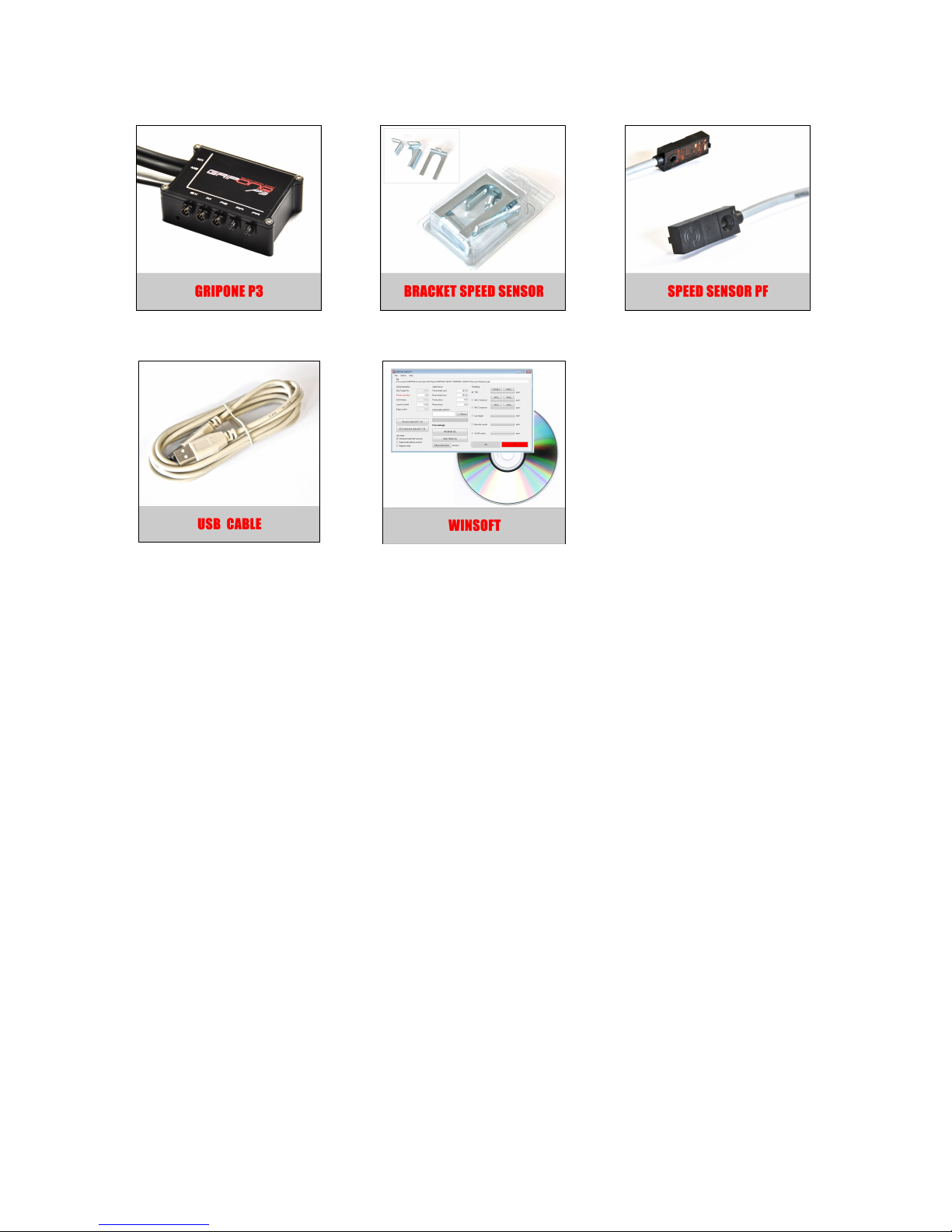
1.0 Included into the kit
ECU
X 1
Kit of bracket
for sensors X 1
Speed sensor X 2
USB cable X 1
Software (CD) X 1
2.0 Security
During the installation of this product, it is recommended to position the motorbike in such a way
that is cannot cause any injury or damage by falling down or moving forward or backward; it is
recommended to use the rear stand or, if necessary, the wheel lock. Make sure that the injection
system is always turned off and that the electrical equipment is not being powered during the
installation of this product (and, as well as, during all assembly phases indicated in this manual).
When adding or removing electrical cables or wiring to/from the motorcycle’s equipment, always
be sure to remove the negative battery terminal before the positive battery terminal. During
reassembly phases, connect the negative terminal last in order to avoid short circuiting the
electrical equipment.
3.0 Installation recommandation
DO NOT RUSH! When installing the GRIPone control unit, make sure that the unit is protected
from excessive vibrations and surrounding elements and that it is clamped firmly. When you use
the adhesive parts (for setting up the control unit or cables), make sure that the mounting surfaces
are clean and free of dust or grease by cleaning them with degreasing solution. When positioning
the wiring, make sure that the wires cannot be pinched or crushed which may cause subsequent
malfunctions, clamp them as necessary. For safe and professional assembly, it is recommended
that you solder the connections when possible and use thermo-tightening bands to isolate the
various conductors. Place the hot part of the welder on the ends of the wires before putting them
in contact with each other. Do not hesitate to contact the vendor/supplier for assistance if you
encounter any difficulties with the installation of this device. WARNING! The GRIPone control

www.gripone.com
unit must be placed where the operating temperature does not exceed 65°C and should be
installed where it will be protected from vibrations and surrounding elements. Locate a flat
surface on which to secure the control unit. Do not secure the unit until the installation of all
other components has been completed and the wiring has been secured.
ATTENTION !
The ECU must placed far from high temperature zone (not more than 65°). The ECU must not be
exposed to vibrations. Locate a flat surface on which to secure the unit. Do not secure the unit
until it is finished installing all other components and wiring.
The use of a traction control system does not prevent the fall caused by improper
use of the throttle of vehicle. For this reason it is advisable to test the functioning
of the system GRIPONE P3 through repeated trials and through small steps. Only
after you had the right confidence and you understood clearly where and how the
device operates on the engine and chassis, try changing the settings.
4.0. Introduction to GRIPONE P3
GRIPONE P3 represents a big innovation in the field of traction control systems for motorcycles.
GRIPONE P3 is the first and only system "stand-alone" that include a central processing unit and
an IMU (Inertial Motion Unit). The IMU, thanks to three accelerometers is able to understand the
tilt of the motorcycle, if this is accelerating or braking, the radius of curvature that the vehicle is
making and more. The control unit processes all information and defines a level of "safe" slip
beyond which intervenes limiting the power.
GRIPONE P3 is a programmable control system. The kit is supplied with a management software
necessary to program the ECU. Each map sent to the control unit contains all the information
necessary for the operation. For information about using the programming software and maps,
refer to the manual GRIPONE P3 Software.
5.0 Electric connection
The electrical installation of the system GRIPONE P3 is done by connecting the GRIPONE ECU to
the main harness of the bike, by connecting the two speed sensors and by connecting the IMU.
5.1 Connection by the plug & play harness
The GRIPONE P3 can be connected to one or two coils or one or two injectors (for the correct
connection refer to the website www.gripone.com where you can also download the base map
specifically for each motorcycle model). For each model of bike a specified connection must be
executed.
The connection is made using original connectors so it is not required any changes to the original
wiring. The installation is possible on all vehicles with transistorized inductive discharge ignition
or on bikes with electronic fuel injection. The GRIPONE P3 can not be installed on ignitions CDI.
By connecting the GRIPONE P3 to the coils of a vehicle with CDI ignition, you'll cause the
breakage.
 Loading...