

Page 1
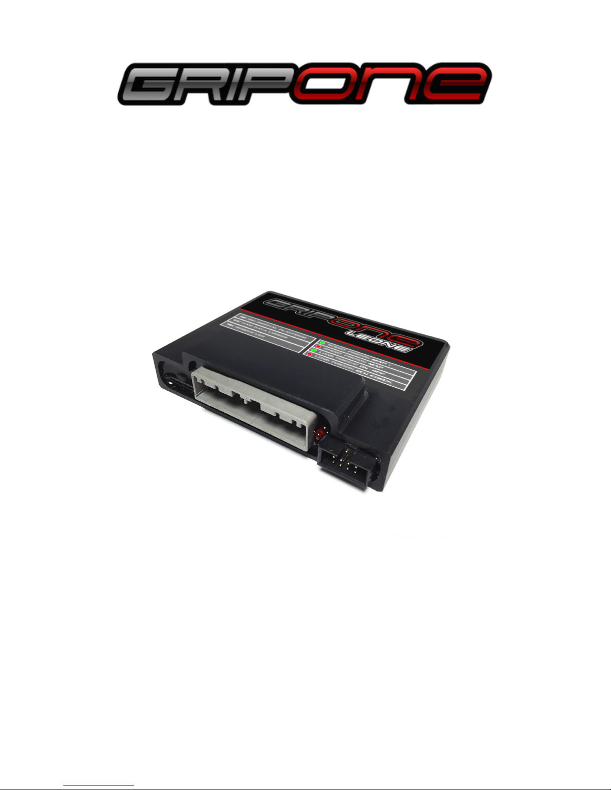
GRIPONE LEONE
Before using GRIPONE read every page of this
manual. The installation of this device requires
attention and accuracy. Please note that you are
installing a device on a vehicle can reach high
speeds. GRIPONE is a professional traction control
system for racing use only. GUBELLINI s.a.s. not be
liable for the consequences resulting from the use of
motorbikes on which it is installed in GRIPONE
system.
Prima di utilizzare il sistema GRIPONE leggere
attentamente tutte le pagine di questo manuale.
L’installazione di questo dispositivo richiede
attenzione. Ricordati che stai installando un
dispositivo su un veicolo in grado di raggiungere
velocità elevate. Il sistema di controllo di trazione
GRIPONE è un dispositivo professionale utilizzabile
nel settore agonistico e non omologato per l’utilizzo
su strada. GUBELLINI s.a.s. non sarà responsabile
delle conseguenze derivate dall’utilizzo dei mezzi su
cui è installato in sistema GRIPONE.
Page 2

1.0 Included into the kit
1 x ECU
1 x IMU (inertial platform)
1 x loom plug&play (with remote buttons)
1 x remote led
1 x bracket for remote buttons
1 x user manual
2 x stickers
1.0 Incluso nel kit
1 x ECU
1 x IMU (piattaforma inerziale)
1 x cablaggio plug&play (con pulsanti a manubrio)
1 x led remoto
1 x staffa per pulsanti
1 x manuale utente
2 x adesivi
2.0 Security
During the installation of this product, it is
recommended to position the motorbike in such
a way that is cannot cause any injury or damage
by falling down or moving forward or backward;
it is recommended to use the rear stand or, if
necessary, the wheel lock. Make sure that the
injection system is always turned off and that the
electrical equipment is not being powered
during the installation of this product (and, as
well as, during all assembly phases indicated in
this manual). When adding or removing
electrical cables or wiring to/from the
motorcycle’s equipment, always be sure to
remove the negative battery terminal before the
positive battery terminal. During reassembly
phases, connect the negative terminal last in
order to avoid short circuiting the electrical
equipment.
3.0 Installation recommandation
DO NOT RUSH! When installing the GRIPONE
LEONE, make sure that the unit is protected
from excessive vibrations and surrounding
elements and that it is clamped firmly. When
positioning the wiring, make sure that the wires
cannot be pinched or crushed which may cause
subsequent malfunctions, clamp them as
necessary.
2.0 Sicurezza
Durante l’installazione di questo prodotto si
consiglia di collocare la moto in modo che
non possa causare ferite o danni, cadendo o
spostandosi avanti o indietro o lateralmente;
si raccomanda l’utilizzo di un cavalletto
posteriore e se necessario il bloccaggio delle
ruote.
Assicurarsi che l’iniezione sia sempre spenta e
che l'impianto elettrico sia non alimentato
durante l’installazione di questo prodotto (e
comunque durante tutte le fasi di montaggio
indicate da questo manuale). Quando si
rimuovono o aggiungono cavi elettrici o
cablaggi all’impianto del veicolo, rimuovere
sempre il terminale negativo dalla batteria
prima del terminale positivo. In fase di
rimontaggio collegare il terminale negativo
come ultimo per evitare corto circuito
all’impianto elettrico.
3.0 Buone norme per l’installazione
NON AVERE FRETTA! Quando installi
GRIPONE LEONE assicurati che l’unità sia
protetta da eccessive vibrazioni, dal calore e
dagli elementi circostanti, e che sia
saldamente fissata. Quando si posizionano i
cablaggi assicurarsi che essi non possano
essere pizzicati o schiacciati e quindi
provocare malfunzionamenti, fissarli con
fascette dove necessario (senza stringere
troppo i cavi incidendoli).
Page 3

ATTENTION !
The ECU must placed far from high temperature
zone (not more than 65°). The ECU must not be
exposed to vibrations. Locate a surface on which
to secure the unit. Do not secure the unit until it
is finished installing all other components and
wiring.
The use of a traction control system does
not prevent the fall caused by improper
use of the throttle of vehicle. For this
reason it is advisable to test the
functioning of the system GRIPONE
LEONE through repeated trials and
through small steps. Only after you had
the right confidence and you understood
clearly where and how the device
operates on the engine and chassis, try
changing the settings.
4.0. Introduction to GRIPONE LEONE
GRIPONE LEONE represents the state of art into
the traction control systems for motorcycles. It is
a system "stand-alone" that operate as traction
control and anti wheelie control. GRIPONE
LEONE can only work with the IMU (Inertial
Motion Unit) connected. The inertial platform
(IMU), thanks to three accelerometers is able to
understand the position of the motorcycle, if it is
accelerating or braking, the radius of curvature
that the vehicle is making and much more. The
control unit processes all information and stop
the spinning very quickly improving the stability
of the bike during the accelerating phase.
ATTENZIONE !
La centralina deve essere posizionata dove
non vi sia una temperatura di esercizio
superiore di 65°C e deve essere protetta da
vibrazioni. Localizzare una superficie adatta,
su cui fissare la centralina. Non fissare la
centralina fino a che non è terminata
l’installazione di tutti gli altri componenti e il
cablaggio.
L'utilizzo di un sistema di controllo
trazione non previene la caduta
causata da un utilizzo inappropriato
del comando del gas e/o del veicolo.
Per questo motivo si consiglia di
sperimentare il funzionamento del
sistema GRIPONE LEONE attraverso
prove ripetute e attraverso piccoli
passi. Solo dopo aver preso la giusta
confidenza e aver capito con chiarezza
dove e come il dispositivo interviene
sul motore e sulla ciclistica, provare a
modificare le regolazioni.
4.0. Introduzione a GRIPONE LEONE
GRIPONE LEONE rappresenta lo stato
dell’arte tra i controlli di trazione per moto. E’
il primo sistema “stand-alone” in grado di
implementare il controllo di trazione e l’anti
impennamento. GRIPONE LEONE può
essere usata solamente in combinazione con
la piattaforma inerziale (IMU). L’IMU, grazie a
tre accelerometri è in grado di capire
l’inclinazione della moto, se questa sta
accelerando o frenando, il raggio di curvatura
che il veicolo sta compiendo e altro ancora.
La centralina elabora tutte le informazioni e
ferma il pattinamento in maniera molto
veloce, aumentando la stabilità della moto
durante la fase di accelerazione
Page 4
5.0 Electric connection
GRIPONE LEONE kit’s include a plug&play loom
to be connected to the main harness of the bike.
No modification are required on the bike.
5.1 Connection of the plug & play loom
The GRIPONE LEONE must be connected to the
ignition coil (or fuel injector only for some
application) of last cylinder.
5.0 Collegamenti elettrici
Il kit GRIPONE LEONE include il cablaggio
plug&play. Non sono richieste modifiche
all’impianto di serie della moto.
5.1 Connessione del cablaggio
GRIPONE LEONE va collegato alla bobina (o
in alcuni casi all’iniettore) dell’ultimo cilindro
del motore.
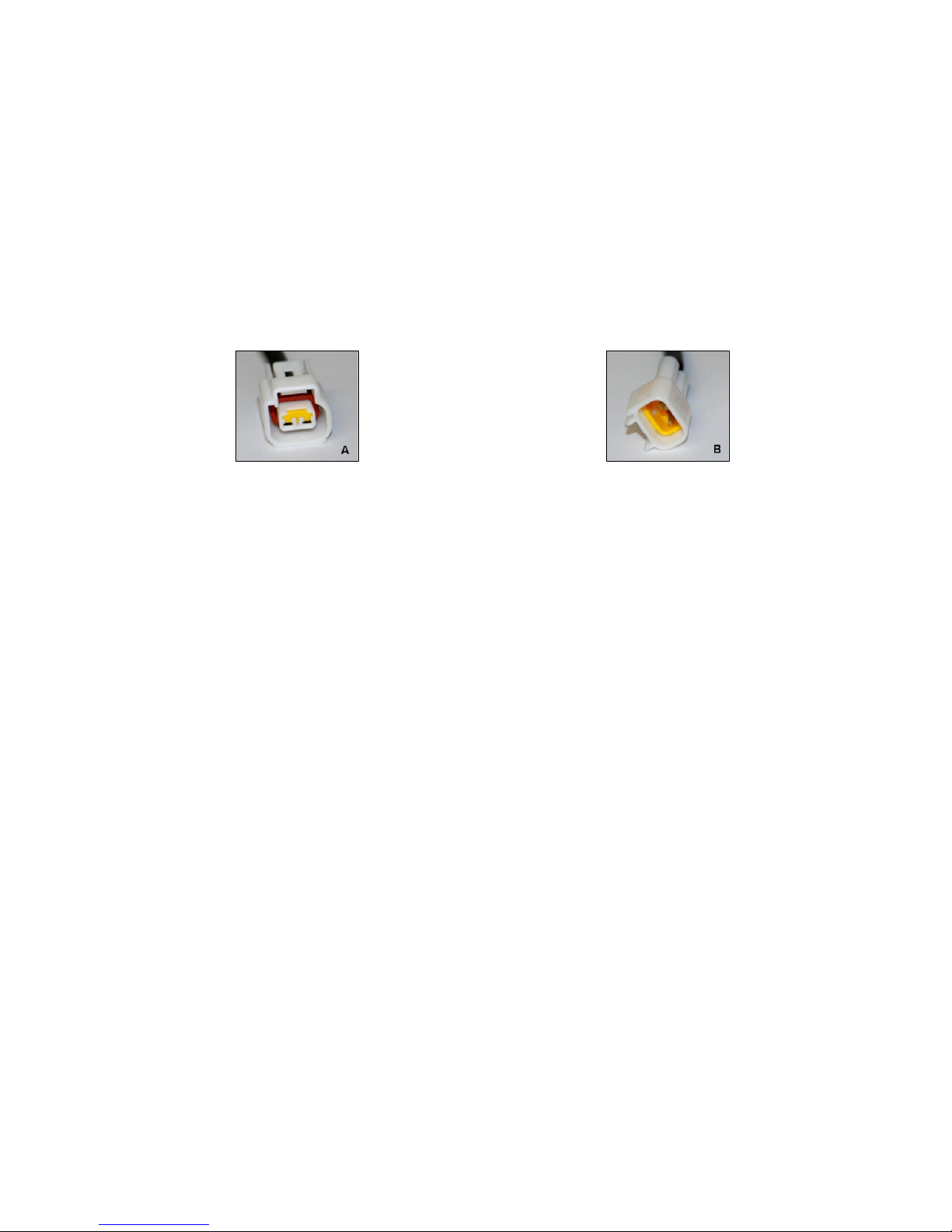
The shape of the connectors may vary according
to the bike. The connector (A) is an example of
female type. The connector (B) is an example of
male type
La forma dei connettori può variare in base al
modello di moto. Per ognuno si avranno
sempre un connettore maschio (B) e un
connettore femmina (A).
Follow those steps to connect the wiring
loom:
1. Take out the fuel tank (and if necessary the
aribox) to have access to the ignition coils (or the
fuel injectors);
2. Unplug the connector of ignition coils (or
injector) of last cylinder;
3. Connect the female connector (A) of
plug&play loom to the coil (or injector);
4. Connect the male connector (B) of plug&play
harness to the factory connector of main harness
(previously unplugged);
5. Connect the black wire of plug&play loom to
the negative pole of battery (or to the chassis or
engine);
6. Lay the plug&play loom by following the
inside of the chassis, to the point where you want
to fix the GRIPONE LEONE control unit. The unit
can be placed under the seat or (even better)
inside the front fairing. Secure the ECU in a
location not too hot and immune to vibration.
Please note that the IMU (you will place further)
must be placed in the front of the bike, so place
Seguire i seguenti passi per il
collegamento:
1. Rimuovere serbatoio e se necessario la
scatola filtro per avere libero accesso alle
bobine (o agli iniettori);
2. Scollegare il connettore dalla bobina (o
dall’iniettore) dell’ultimo cilindro;
3. Collegare il connettore femmina (A) del
cablaggio plug&play alla bobina (o
all’iniettore;
4. Connettere il connettore maschio (B) del
cabaggio plug&play al connettore femmina
del cablaggio di serie (precedentemente
scollegato);
5. Collegare il filo nero (con il capicorda a
“occhiello”) del cablaggio plug&play a massa
o al negativo della batteria;
6. Stendere il cablaggio plug&play lungo la
parte interna del telaio, fino al punto in cui si
desidera posizionare la centralina GRIPONE
LEONE. Prego di notare che la IMU adrà
piazzata nella parte anteriore della moto e
quindi la centralina non dovrà stare troppo
Page 5

the ECU not too far.
7. Connect the unit GRIPONE LEONE to the
main connector of plug&play loom;
8. Reassemble the airbox and the tank;
5.2 IMU placement
The positioning of the IMU on the bike is very
important. If it is not done in the correct manner,
the control unit may not work. The IMU must be
connected to the wiring loom where there is the
“IM” marker. The IMU must be placed in the
front end of the bike, far from heat and isolated
by the vibration. Use the foam included into the
box to isolate it. On the face of IMU you can see
two arrows pointing to the Z axis and the Y axis.
The Y arrow must point the front of the bike (as
much horizontal as possible). The Z arrow must
point the ground (as much vertical as possible.
5.3 Connecting the Remote LED
GRIPONE LEONE has a remote LED that can be
placed near the dashboard and it is helpful to
check the funtionalities of the unit. Connect the
remote LED to the connector with marker “RE”
of plug&play loom. Place it where you can see it
when you ride the bike. By different typer of
blink, the remote led can inform you about the
status and functions of ECU.
lontana da essa.
7. Collegare la centralina GRIPONE LEONE al
connettore principale del cablaggio
plug&play;
8. Rimontare la scatola filtro, il serbatoio e la
sella;
5.2 Posizionamento della IMU
Il posizionamento della IMU è molto
importante e se non fatto correttamente, il
sistema potrebbe non funzionare. L’IMU va
collegata al cablaggio al ramo marcato con
“IM”. Va posizionata nella parte anteriore
della moto , lontana da fonti di calori dirette
come il motore e va isolata dalle vibrazioni.
Usa la spugna inclusa nella confezione per
avvolgerla e fissarla ad una parte rigida della
moto. Il posizionamento deve essere fatto in
modo che la freccia Y punti verso il senso di
marcia (orizzontale) e la freccia Z punti verso il
suolo (perpendicolare).
5.3 Collegare il Remote LED
GRIPONE LEONE è dotato di un LED remoto
che può essere posizionato sul cruscotto ed è
utilizzato per verificare le funzionalità della
centralina. Collegare il LED remoto al
connettore del cablaggio plug&play marcato
“RE”. Posizionalo in un punto visibile.
Tramite diversi tipi di lampeggi, il led remoto
può informarti riguardo lo stato e le funzioni
della ECU.
Page 6
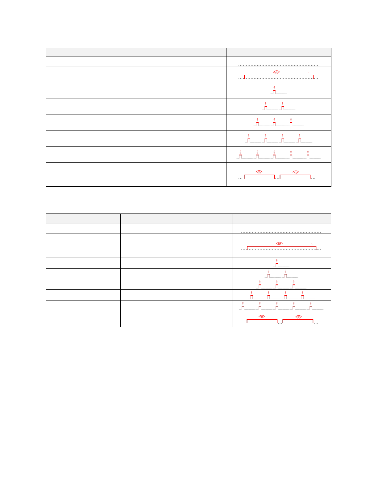
How it works
Description
Function
Light scheme
Led stay off
Stand by mode
Led stay on
GRIPONE is reducing the power (because
traction control or anti wheelie are working)
Led show 1 short
flash
User select the “Control level” 1 by the
remote buttons
Led show 2 short
flashes
User select the “Control level” 2 by the
remote buttons
Led show 3 short
flashes
User select the “Control level” 3 by the
remote buttons
Led show 4 short
flashes
User select the “Control level” 4 by the
remote buttons
Led show 5 short
flashes
User select the “Control level” 5 by the
remote buttons
Long blink
There is a problem on the IMU. Pay
attention because the system can not work
properly !!!
Come funziona il LED remoto:
Descrizione
Funzione
Schema luci
Il led rimane spento
Modo stand by
Il led acceso fisso
La ECU stà tagliando potenza (tramite il
controllo di trazione, il controllo della
partenza o l’anti impennamento)
1 lampeggio singolo
Attivata il livello controllo 1
2 lampeggi singoli
Attivata il livello controllo 2
3 lampeggi singoli
Attivata il livello controllo 3
4 lampeggi singoli
Attivata il livello controllo 4
5 lampeggi singoli
Attivata il livello controllo 5
Lampeggio lungo
Problema alla piattaforma inerziale. Il
sistema non può lavorare correttamente
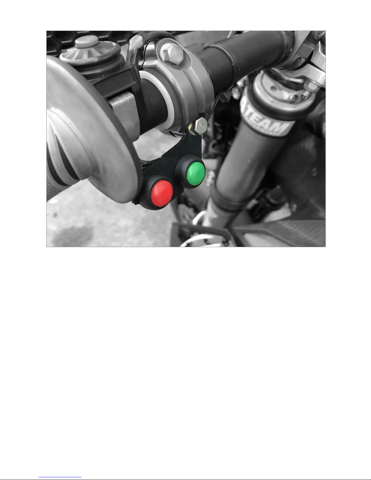
6.0 Remote buttons
The kit include two remote buttons and a
mounting bracket by which you can positioning
the buttons on handle bar. By those buttons
you can switch ON and
OFF
the system, entry
into the “
manual programming mode
” or
change the
control level
.
We suggest to fix the bracket of buttons by the
screw of clutch lever in the left handle bar.
6.0 Pulsanti remoti
Il kit plug&play include due pulsanti remoti e
una staffa che permette di collocarli sul
manubrio. Tramite questi pulsanti puoi attivare
o disattivare il sistema, attivare la
programmazione manuale
o cambiare il livello
del controllo di trazione TC.
Suggeriamo di fissare la staffa dei pulsanti alla
vite del bracciale della leva frizione.
Page 7
6.1 On – Off
Keep pressed the green button (for 4 seconds)
and release it to switch off the system. When the
system is
off
, the green led (on the ECU) stay on.
Keep pressed (for 4 seconds) the green button
and release it again to switch on the system.
When the system is on, the green led (on the
ECU) blink quickly (1Hz).
6.2 ECU check
GRIPONE LEONE cannot be tested with the bike
stopped because it needs the accelerations
detected by the IMU. If you want to check that
ECU works properly and the system is corrected
mounted, you can start the “ECU check mode”.
• Keep pressed the red button for 4 seconds
and release it.
• For 3 seconds, the ECU will cut the power on
6.1 On – Off
Tieni premuto il pulsante verde per 4 secondi
per disattivare il sistema. Con il sistema
disattivato il led verde sulla centralina rimane
acceso. Tieni premuto il pulsante verde per 4
secondi per riattivare il sistema (on mode).
Con il sistema attivato il led verde sulla
centralina lampeggerà normalmente (1Hz).
6.2 Controllo ECU
GRIPONE LEONE non può essere provata da
moto ferma perché richiede le accelerazioni
rilevate dalla IMU. Per verificare che tutto è
montato correttamente e che la ECU sia
funzionante puoi attivare il controllo ECU.
• Tieni premuto il pulsante rosso per 4
secondi e rilascialo.
• Per 3 secondi la centralina taglierà
Page 8

the engine, simulation a sliding of rear tire.
• You should heard different sound on the
engine. If it is difficult heard the cut, we
suggest to try again keeping RPM around
5000.
6.3 Traction control levels
GRIPONE LEONE is pre-programmed with a
base map (which has an average traction control
and average anti wheelie). You can use the
GRIPONE LEONE without use the computer.
By the remote buttons, you can ch ange the
traction control and anti wheelie between 5
different levels (from level 1 to level 5). Level 1 is
the lightest control level (where you don’t feel so
much control). Level 5 is the most invasive
control level (where you can feel a lot of traction
control and anti wheelie).
• Press the green button to switch to the
above level of control (example from 2 to 3).
• Press the red button to switch to the below
level of control (example from 5 to 4).
Every time you change the control level, the
remote led blink a number of time same as the
level you selected. For example if you switch
from level 2 to level 3, the remote led will blink 3
times).
When you are using the level 5 and you
press one more time the green button
nothing will happen. When you are using
the level 1 and you press the red button,
nothing will happen.
NOTE: GRIPONE LEONE allow you many more
adjustaments of traction control and anti
wheelie. To have access to all the adjustment
options you have to install the software
WINSOFT (included into the memory stick) and
program the ECU by USB cable.
6.4 IMU Initialization
The IMU inside the kit of GRIPONE LEONE is
initialized in factory.
(FOR THAT REASON YOU
potenza cosi da far cambiare suono al
motore.
• Se risulta difficile sentire la variazione
consigliamo di mantenere il regime di
rotazione attorno a 5000 RPM.
6.3 Livelli controllo di trazione
GRIPONE LEON E è pre-programmata con
una mappa base (che prevede un controllo di
trazione medio, un anti impennamento medio
e il controllo per la partenza spento). Puoi
utilizzare il sistema senza dover programmare
la centralina con il computer. Tramite i
pulsanti puoi variare il controllo di trazione e
l’anti impennamento su cinque livelli di
sensibilità. Con il livello 1 otterrai il minimo
livello di controllo trazione e anti
impennamento. Con il livello 5 otterrai il
livello massimo di controllo trazione e anti
impennamento.
• Premi il pulsante verde per spostarsi al
livello successivo (esempio dal 2 al 3).
• Premi il pulsante rosso per spostarsi al
livello precedente (esempio dal 5 al 4).
Ogni volta che viene cambiato il livello di
controllo di trazione, il remote led emetterà
un numero di flash pari al livello selezionato
(esempio selezionando il livello 3, verranno
emessi 3 lampeggi).
Se sei nel livello 5 e premi il pulsante verde
non succederà nulla, così come se usi il livello
1 e premi il pulsante rosso.
NOTA
: GRIPONE LEONE permette molte
altre regolazioni del controllo di trazione e
dell’anti impennamento. Per avere accesso a
tutte le possibilità di regolazione devi
installare il software WINSOFT e
programmare l’ECU via USB.
6.4 Inizializzazione IMU
GRIPONE LEONE è fornito con l’IMU già
inizializzata
(QUINDI NON SERVE
Page 9
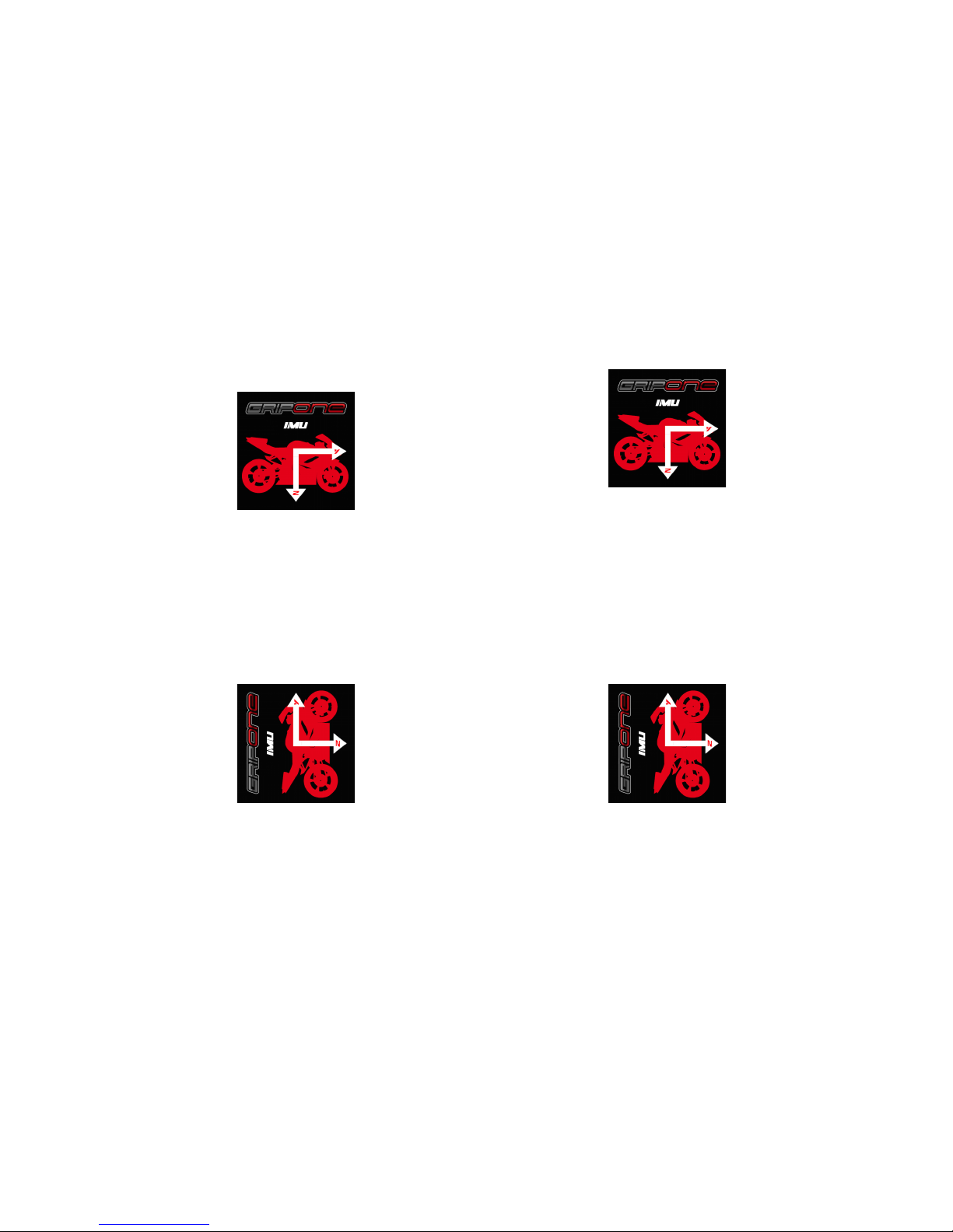
DON’T HAVE TO INITIALIZE IT !!!)
. In case you
have to replace the IMU (because it is damaged)
you can initialize the new IMU following those
steps:
• Connect the new IMU to the wiring loom
• Start the engine of the bike
• Keep pressed both buttons (for 4 sec.) and
release them. The red led on ECU will switch
on
• Place the IMU like shown in picture (A). With Y
arrow pointed to the front and Z arrow pointed
to the ground
pic.A
• Press the red button for half second. The red
led will switch off and the green led will switch
on
• Place the IMU as shown in picture (B), with the
Y arrow to the sky and the Z arrow to the front
pic.B
• Press the green button for half second
• Wait the flashing at end of procedure and
switch off the engine.
The IMU is now initialized and ready to be used.
NOTE: the anti wheelie control needs an
extreme precision of IMU signal. For that
reason, every time you start the bike, the
system proceed with the measurement of
Z axis’s offset. For that reason. when you
start the engine, can be helpfull keep the
bike most straight as possible.
INIZIALIZZARLA!!!)
. Nel caso di rottura della
IMU c’è la possibilità di inizializzare una nuova
IMU tramite i pulsanti. Procedere seguendo i
passi indicati:
• Collegare la nuova IMU al cablaggio
• Accendere la moto
• Premere per 4 sec. entrambi i pulsanti e
rilasciarli. Si accenderà il led rosso sulla ECU
• Posizionare la IMU come la figura (A) con la
freccia Y verso avanti e la freccia Z verso il
terreno
fig.A
• Premere il pulsante rosso per mezzo
secondo. Si spegnerà il led rosso e si
accenderà quello verde
• Posizionare la IMU come mostra la figura
(B), con la freccia Y verso l’alto e la freccia Z
in avanti
fig.B
• Premere il pulsante verde per mezzo
secondo
• Attendere il lampeggio di fine procedura e
spegnere la moto
Adesso la IMU è linearizzata e pronta.
NOTA: l’anti impennamento richiede una
estrema precisione dalla IMU. Per questo ad
ogni avviamento viene effettuato la misura
dell’offset sul canale Z. E’ opportuno in
questa fase mantenere la moto più dritta
possibile
Page 10
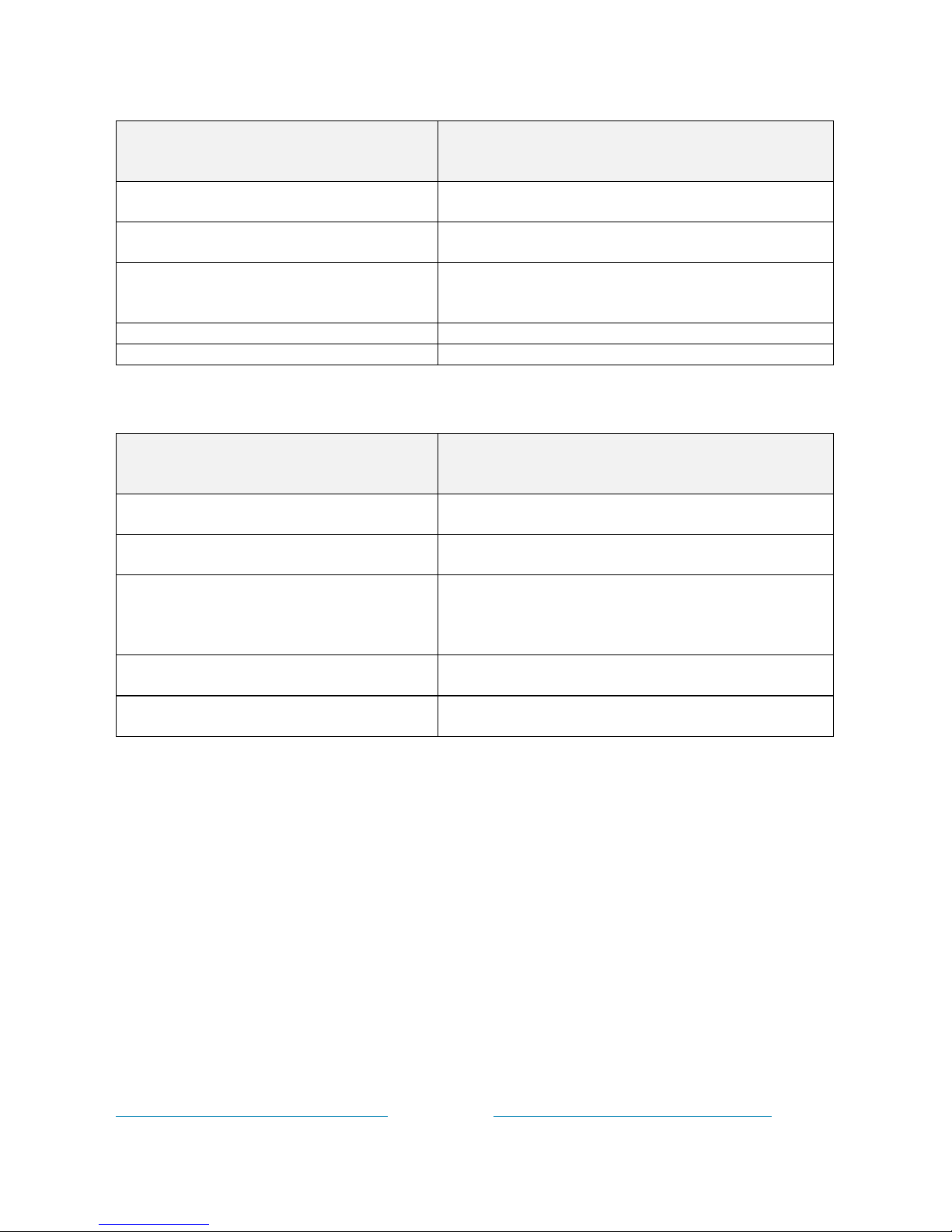
How the buttons work:
Action on buttons
Description
Short press of
GREEN
button
It change to the next traction control level (ex. change
from level 1 to level 2)
Short press of
RED
button
It change to the previous traction control level (ex. change
from level 4 to level 3)
Long press of
GREEN
(>3sec)
Change status from ON to OFF and viceversa. Keep
pressed 4 sec to switch the system off. Keep pressed
againg 4 sec to switch the system on.
Long press of
RED
(>3sec)
ECU check
Long press of
GREEN
and
RED
(>3sec)
IMU initialization
Come funzionano i pulsanti:
Azione sul pulsante
Descrizione
Pressione del pulsante
VERDE
Passa al livello di controllo trazione successivo (es. cambia
dal livello 1 al livello 2)
Pressione del pulsante
ROSSO
Passa al livello di controllo trazione precedente (es.
cambia dal livello 4 al livello 3)
Pressione prolungata del pulsante
VERDE
(>3sec)
Cambia stato da ON a OFF e viceversa. Mantenere
premuto per 4 sec. e rilasciare per disattivare il sistema.
Mantenere nuovamente premuto per 4 sec. e rilasciare
per riattivare il sistema.
Pressione prolungata del pulsante
ROSSO
(>3sec)
Attivazione controllo ECU.
Pressione prolungata del pulsante
VERDE
e
ROSSO
(>3sec)
Azzeramento IMU
7.0 Program the ECU by USB cable
GRIPONE LEONE is pre-programmed with a
base map that cover a large range of user. By
the buttons you can change the level of traction
but you can not change the anti wheelie or the
launch control. If you want access to all the
parameters of GRIPONE LEONE, you have to
install the software WINSOFT (on your
computer) and use it to program the ECU by the
USB cable (optional).
7.1 Install WINSOFT
Open your web browser, go to our web site
www.gripone.com/gripone_winsoft2/ and click
to “INSTALLA” to download the file setup.exe.
7.0 Programmare la ECU tramite la USB
GRIPONE LEO NE è pre-programmata con
una mappa base che copre un ampio range di
utilizzo. Tramite i pulsanti puoi cambiare il
livello di controllo trazione ma non puoi
cambiare l’anti impennamento o il controllo
della partenza. Per farlo devi installare il
software WINSOFT (sul tuo computer) e
programmare la tua centralina tramite il cavo
USB (opzionale).
7.1 Installazione WINSOFT
Apri il browser e vai all’indirizzo
www.gripone.com/gripone_winsoft2/ e clicca
su “INSTALLA” per scaricare il file setup.exe.
Page 11
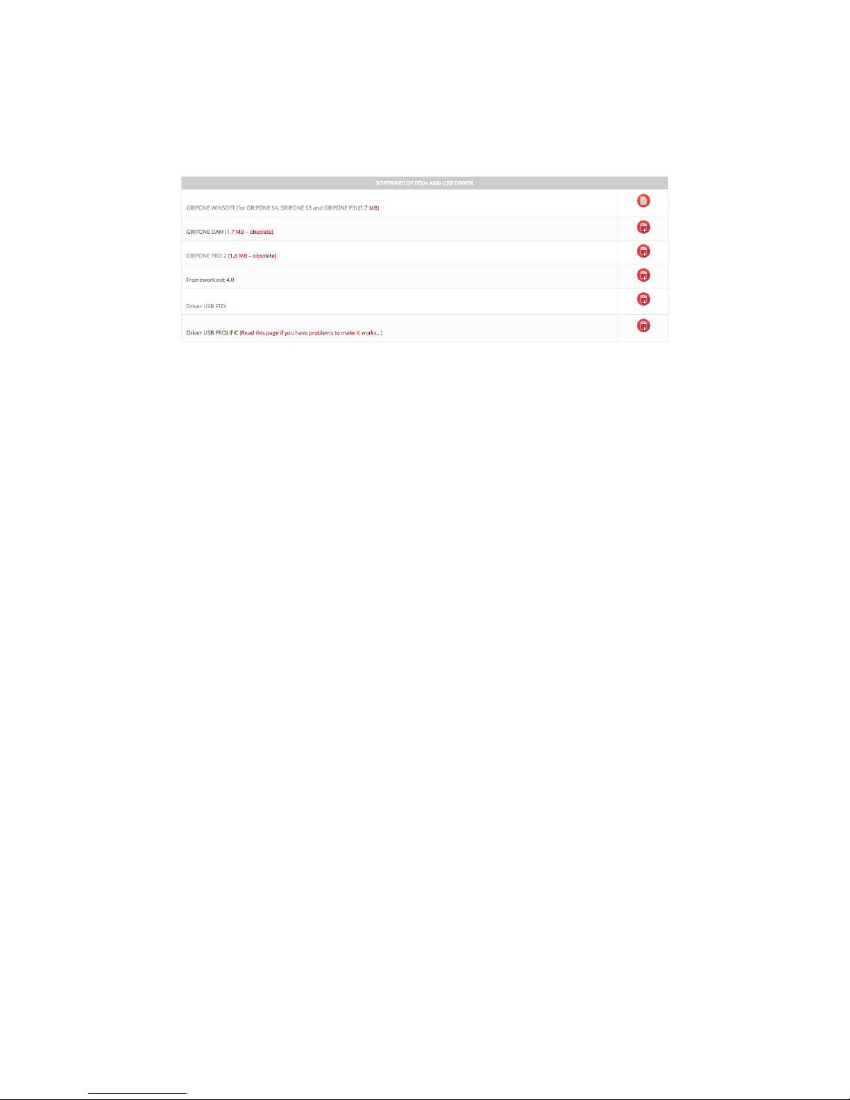
Run setup.exe and follow the procedure of
installation. Go on page DOWNLOADS >
Manual & software of our web site. Download
and install the driver USB FTDI. Restart your PC.
Eseguilo e segui la procedura di installazione.
Vai alla pagina DOWNLOADS > Manual &
software sul nostro sito. Scarica e installa il
drive USB FTDI. Riavvia il tuo PC.
7.2 Program the ECU
After the installation of WINSOFT ans USB
driver, you can program the ECU. GRIPONE
LEONE can be programmed with engine off.
• Connect the USB cable (optional) to the ECU
• Press READ ECU
• Wait the reading procedure
• Modify the parameter as you want in the
CONFIGURATION area
• (if you want) Save the new parameters on your
PC by menu File > Save As
• Press PROGRAM ECU to program the ECU
with the new parameters
• Wait the end of procedure
• Disconnect the USB cable
At the end of procedure, the ECU is ready to be
used.
NOTE: we suggest to save the map you
created, so you can re-load it into WINSOFT any
moment you want. To save the map select Save
As from the menu File.
7.2
Programmare la ECU
Dopo l’installazione di WINSOFT puoi
programmare l’ECU. GRIPONE LEONE può
essere programmata con il motore spento.
• Collega il cavo USB
• Premere READ ECU
• Attendere la lettura dalla ECU
• Modificare i parametri a video nell’area
CONFIGURATION
• (se desideri) Salvare i nuovi parametri in un
file tramite il menu File > Save As
• Premere PROGRAM ECU per programmare
la ECU con i nuovi parametri
• Attendere la fine procedura
• Scollegare la USB
Alla fine della procedura, l’ECU è pronta per
essere usata.
NOTA: ti suggeriamo di salvare la mappa che
hai appena creato, cosi da poterla ri-caricare
in WINSOFT in ogni momento. Per salvare la
mappa seleziona
Save As
dal menu
File
.
Page 12
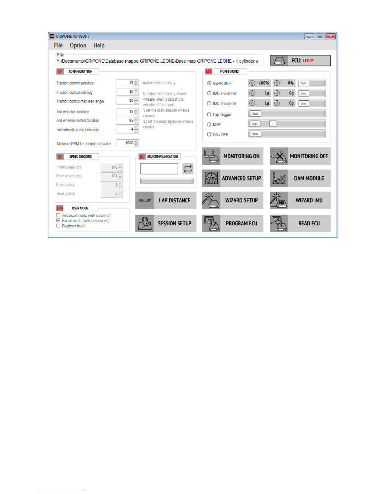
7.3 Parameters
• TRACTION CONTROL SENSITIVE – it define
the sensitive of traction control. 20 is
maximum traction control. 1 is minimum
traction control.
• TRACTION CONTROL INTENSITY – it define
the progression of traction control. If you want
to quickly stop the spinning (strong effect of
traction control) use high values (12 to 20). If
you want a soft effect of traction control use a
small values (1 to 8).
• TRACTION CONTROL MAX LEAN ANGLE – it
define the sensitive of traction control in the
middle of the corner (when your bike is fully
leaned). Use high values (12 to 20) if you want
a high sensitive in the middle of corner. Use
small values (1 to 8) if you want to reduce the
sensitive in the middle of corner.
• ANTI WHEELIE SENSITIVE – it define the
sensitive of anti wheelie control. Increase its
value if you want to cut the power as soon the
tire lift from the ground. Reduce its value if
7.3 Parametri
• TRACTION CONTROL SENSITIVE –
stabilisce la sensibilità del controllo di
trazione. 20 è massimo controllo. 1 è
minimo controllo
• TRACTION CONTROL INTENSITY –
stabilisce la progressione del controllo di
trazione. Usa valori alti (12-20) se vuoi
fermare velocemente il pattinamento. Usa
valori piccoli (3-8) se vuoi ottenere un
effetto dolce dal controllo di trazione.
• TRACTION CONTROL MAX LEAN ANGLE
– definisce la sensibilità del controllo di
trazione a centro curva (quando la moto è
completamente inclinata. Usa valori alti (12-
20) per avere una grande sensibilità alle
perdite di trazione a centro curva. Usa valori
bassi (2-8) per ridurre la sensibilità a centro
curva.
• ANTI WHEELIE SENSITIVE – definisce
la sensibilità dell’anti impennamento.
Aumenta il valore per ridurre la potenza
Page 13

you want permit more wheelie.
• ANTI WHEELIE DURATION – The strategy
of anti wheelie cut the power every time the
front tyre lift from the ground. DURATION
define the duration (in centitimes of seconds)
of cut. Increase its value to make it longer.
Reduce its value to make it shorter
• ANTI WHEELIE INTENSITY – it define the
amount of power reduction when the front
tyre lift from the ground. Increase its value to
stop quickly the wheelie. Reduce its value to
have a smooth effect.
7.4 Control levels and maps
GRIPONE LEONE implements the traction
control and the anti wheelie based on the map
loaded in the ECU and based on the selected
control level (choosen by the remote buttons
from 1 to 5).
You can use GRIPONE LEONE without change
the map (by USB) and using only the 5 control
levels available by the buttons.
Anyway it is important understand how the map
and the control levels are connected.
The map pre-programmed in the ECU (by the
factory) rapresent the base by which the ECU
generates the 5 control levels. This means that
changing the map, you can change also the
control levels. The control level 1(generated by
the factory map can be different compared to
the control level 1 generated by your custom
map (made by WINSOFT).
Example: the value of TRACTION CONTROL
SENSITIVE (of factory map) is 16. If you generate
a new map (by WINSOFT) with TRACTION
CONTROL SENSITIVE = 9, the control level 1
will be less sentitive to the rear tire’s slide.
appena la ruota si solleva dal terreno.
Riduci il valore se vuoi permettere un certo
impennamento prima di tagliare la potenza.
• ANTI WHEELIE DURATION – L’anti
impennamento taglia la potenza ogni volta
che la ruota si solleva. DURATION definisce
la durata (in centesimi di secondo) della
riduzione di potenza. Aumenta il valore se
vuoi prolungare il taglio di potenza, riduci il
valore se vuoi ottenere solamente un taglio
breve.
• ANTI WHEELIE INTENSITY – definisce
la quantità di potenza da ridurre per
riportare la ruota anteriore a terra.
Aumenta il valore per ottenere un taglio
deciso. Riduci il valore per ottenere un
taglio dolce.
7.4 Livelli di controllo e mappe
GRIPONE LEONE attiva il controllo di trazione
e l’anti impennamento in funzione della
mappa che è caricata nella ECU e in funzione
del livello di controllo selezionato tramite i
pulsanti (da 1 a 5).
Puoi utilizzare GRIPONE LEONE senza mai
cambiare la mappa (via USB) ed utilizzando
solamente i 5 livelli di controllo disponibili sui
pulsanti.
E’ importante però capire come la mappa e i
livelli di controllo siano collegati.
La mappa (caricata in fabbrica o via USB)
rappresenta la base di partenza sulla quale
GRIPONE LEONE genera i 5 livelli di
controllo. Questo significa che variando la
mappa, vario anche i livelli di controllo. Il
livello 1 (che ottengo con la mappa base pre-
programmata in fabbrica) potrebbe non
corrispondere al livello 1 che ottengo con una
mappa generata successivamente tramite
WINSOFT.
Esempio: il valore di TRACTION CONTROL
SENSITIVE della mappa base (pre
programmata in fabbrica) è 16. Se cambio
questo valore con 11, il livello ci controllo 1
risulterà meno sensibile al pattinamento della
Page 14

ruota posteriore.
Page 15

Page 16

designed, owned and made by
GUBELLINI s.a.s. di Diego Gubellini & C.
Via Euridia Bergianti 10/B
40059 Medicina (BO) Italy
P.IVA IT03466001207
www.gripone.com - [email protected]
 Loading...