

Page 1
Grip Factory Munich
YOUR INNOVATIVE PARTNER FOR CAMERA SUPPORT
GF-Primo / GF-Secondo
Instruction Manual
Grip Factory Munich GmbH
Fürholzener Straße 1
85386 Eching bei München
Germany
Valid: Jul 2012
Tel.: +49 (0) 89 319 0 129-0
Fax: +49 (0) 89 319 0 129-9
e-Mail: info@g-f-m.net
http://www.g-f-m.net
Page 2

GF-Primo / GF-Secondo Dolly System Instruction Manual
Page:
1
Contents:
SAFETY GUIDELINES................................................................................................2
Technical Specs for GF-Primo - / GF-Secondo Dolly..................................................4
The Base Dolly............................................................................................................6
Changing the batteries.............................................................................................................6
Connecting the Platforms.........................................................................................................6
Wheel arm adjustment..............................................................................................................8
Connecting the Steering Handle:..............................................................................................9
Adjusting the angle of the Steering Handle:............................................................................10
Adjusting the length of the Steering Handle:...........................................................................10
Connecting the HCU to Steering Handle.................................................................................11
GF-Primo Steering modes:........................................................................................12
GF-Primo‘s 3 steering modes and selector position:...............................................................13
GF-Secondo Steering modes:...................................................................................14
GF-Secondo’s three steering modes and their selector positions:...........................................15
Combi-Wheels – GF-Primo & GF-Secondo:..............................................................16
Disconnecting the wheels from the steering:...........................................................................16
Going on Track:......................................................................................................................17
The Multifunctional Turnstile Mount:.........................................................................18
Removing the Column with the Carry Bars:..............................................................19
Hand Control Unit Components................................................................................20
Starting off..............................................................................................................................21
To connect the cable from the HCU to Electronic:...................................................................23
Hand Control Unit Display......................................................................................................23
Adjusting the Speed or Ramp.................................................................................................24
Generating Movement............................................................................................................24
To select the HCU Mode........................................................................................................24
Setting a new lower and upper limit........................................................................................25
The HCU Modes....................................................................................................................25
Emergency Operation of the Column........................................................................34
Synchronizing the Hand Control Unit and Column....................................................36
Calibrating the column...............................................................................................37
Trouble Shooting.......................................................................................................38
ASSEMBLING THE GF-Primo Jib:............................................................................42
Selecting the “Jib On” mode...................................................................................................47
Page 3

GF-Primo / GF-Secondo Dolly System Instruction Manual
Page:
2
SAFETY GUIDELINES
Adherence to the instruction manual:
The set-up instructions must be read and understood before set-up or operation. The dolly may only be
assembled in accordance with the manufacturer’s instruction manual. The manufacturer’s technical
specifications and limits (maximum rated loads etc) must be adhered to at all times and in no way exceeded.
Warranty:
The manufacturer accepts no liability for damages or injuries for incidents or accidents occurring due to
negligence by the crane operator or misuse of the crane or disregarding the instruction manual.
Assembling and operation of the dolly:
The Dolly may only be set-up or operated by trained and experienced personnel. To assemble and operate
the dolly at least 1 trained person is required. To avoid misuse by untrained personnel, the dolly should be
dismantled / switched off when not in use or under supervision.
The crane may not be set-up or operated under the influence of alcohol, drugs or any other intoxicating
substances. The respective protective clothing e.g. gloves, should be worn.
Stability of the crane system:
Before assembling or using the dolly ensure that the ground surface is stable and cannot give way. The
ground surface must be stable enough to support at least 1000 kg/m2 = 2200 lbs/ sq yard.
Dolly operation with the GF-Primo Jib is only allowed with solid tires and use with pneumatic wheels is not
allowed. Before and while using the dolly wheels should be inspected.
Intended use of the Dolly system and use of the Dolly system with Jib Arm:
The Dolly is a mobile personnel and camera support system for use on sets and studios with even and level
ground / floors. Also for use on GF-Track.
Standard dolly operation consists of a for lifting 1 to 2 persons and camera or lifting the camera only, without
personnel on board, electromechanical column for lifting 1 to 2 persons and camera or lifting the camera
only, without personnel on board.
In Jib mode a pan and tilt arm is mounted for lifting 1 to 2 persons and camera or lifting the camera only,
without personnel on board
In accordance to the safety guidelines the dolly/jib is only allowed to be used on solid, level and stable
ground with solid wheels, not pneumatic wheels.
The dolly/jib movement on the ground, rotation of the column is managed by at 1 to 2 experienced, trained
and authorised personnel from the hand grips and /or the provided steering handles.
Panning movement of the turnstile mount / column can also be made by the personnel sitting on the
column/dolly when seated on the provided seats.
Vertical lift of the column is controlled via wireless or cable control operated by an experienced, trained and
authorised person.
Operation of the dolly/jib is only allowed within the limits and guidelines mentioned in this instruction manual.
The dolly must be operated on level, stable surfaces at all times or on dolly track. Whether operating or
moving the dolly on track or on a solid ground surface it is essential that the track or surface is completely
level, stable and free from obstructions.
When operating the dolly on track, ensure that the track is level, properly laid, constructed and supported.
The correct underlay must be used to ensure that the track and underlay are secured against moving,
slipping and collapse. Ensure that the underlay meets the specified support and stability requirements. Only
GFM Track or comparable track systems with a payload capacity of 1200kg / 2640lbs and a maximum track
runner distance of 640mm / 25inches (measured inside edge to inside edge) may be used.
Extreme caution if tracking on curved track (not faster than a slow walking pace)!
Use of the dolly on insert vehicles, camera cars or any motorised vehicle is not allowed. The
manufacturer accepts no liability for damages or injuries for incidents or accidents occurring due to use of
the dolly on insert vehicles, camera cars or any other motorised vehicles.
Operation of the Dolly/ Jib:
The complete lift and panning range of the dolly/jib must be kept clear of obstructions at all times. A safety
clearance of 1m / 3' 3" must be observed on all sides of the dolly/jib during operation. Only authorised,
trained and experienced personnel are allowed to operate the dolly/jib. The dolly/jib may not be set-up or
operated under the influence of alcohol, drugs or any other intoxicating substances. The respective
protective clothing e.g. gloves, should be worn.
The dolly may not be used in the direct vicinity of high voltage power cables. To avoid accidents due to
misuse in the vicinity of high voltage power cables, Safety Guidelines especially BGV A1 and A2 (formerly
Page 4

GF-Primo / GF-Secondo Dolly System Instruction Manual
Page:
3
VBG 1 and 4) as well as VDE regulations (especially 0105 part 100) must be adhered to. If the nominal
voltage cannot be determined, a minimum clearance of 5m / 16ft must be kept at all times.
Failing to do so can cause fatalities!
Personnel on board the jib's platform must use safety belts at all times. They should not make any sudden,
abrupt movements or lean out over the side of the platform. No loose objects may be stored or placed on the
dolly platform.
In the interest of safety, when operating or moving the dolly/jib, abrupt, sudden movements of the dolly
should be avoided. An element of risk remains by people moving in the operational range of the dolly/jib. The
dolly operator has to be trained on that and is only allowed to operate the equipment in a safe range.
Before operating the dolly/jib all connections, mounted accessories, safety pin as well as every connecting
bolt must be checked for a proper fit.
Dolly accessories:
For safety reasons only original accessories manufactured by GFM may be used with the dolly.
Procedure in case of accident or damage:
In case of accidents caused by disregarding the manufacturer’s instruction manual, please proceed as
follows:
o The manufacturer should be immediately informed of any damage to the dolly and the severity of the
damage. Damaged dolly parts should be sent to the manufacturer for evaluation, repair or
replacement.
Use of the dolly with damaged parts is not allowed. The manufacturer accepts no liability for damage
or injuries for incidents or accidents occurring due to the use of damaged parts on the dolly.
o In case of damage or accidents with injured people local applicable as well as employment property
right regulations may be adhered.
Safety Guidelines for dolly operation:
To avoid collisions, ensure that the columns lift range is free from obstructions!
When working with off-set arms ensure that the mounted payload is counter balanced! Never exceed the
manufacturers payloads
In an open space the wireless mode range is approx. 100m / 330yards
In general, the hand control unit should never be left on when not in use or when not under supervision.
To avoid unwanted movement of the column due to misuse or accidental activation of the rocker switch /
hand control unit, ensure that the main electronic switch is OFF when not in use or not under supervision.
The equipment must be handled carefully at all times.
Do not operate or drive the column without payload on the column. At least 1 person and camera
should be on the column when it’s moving.
Attention: Should the HCU software be older than versionr 3.8.5 or the electronic
be older than version 3.7.3 or if you gave a software where it is not
possible to check the version please note that after using the
Emergency switch the column must be calibrated (see page 39)
Page 5
GF-Primo / GF-Secondo Dolly System Instruction Manual
Page:
4
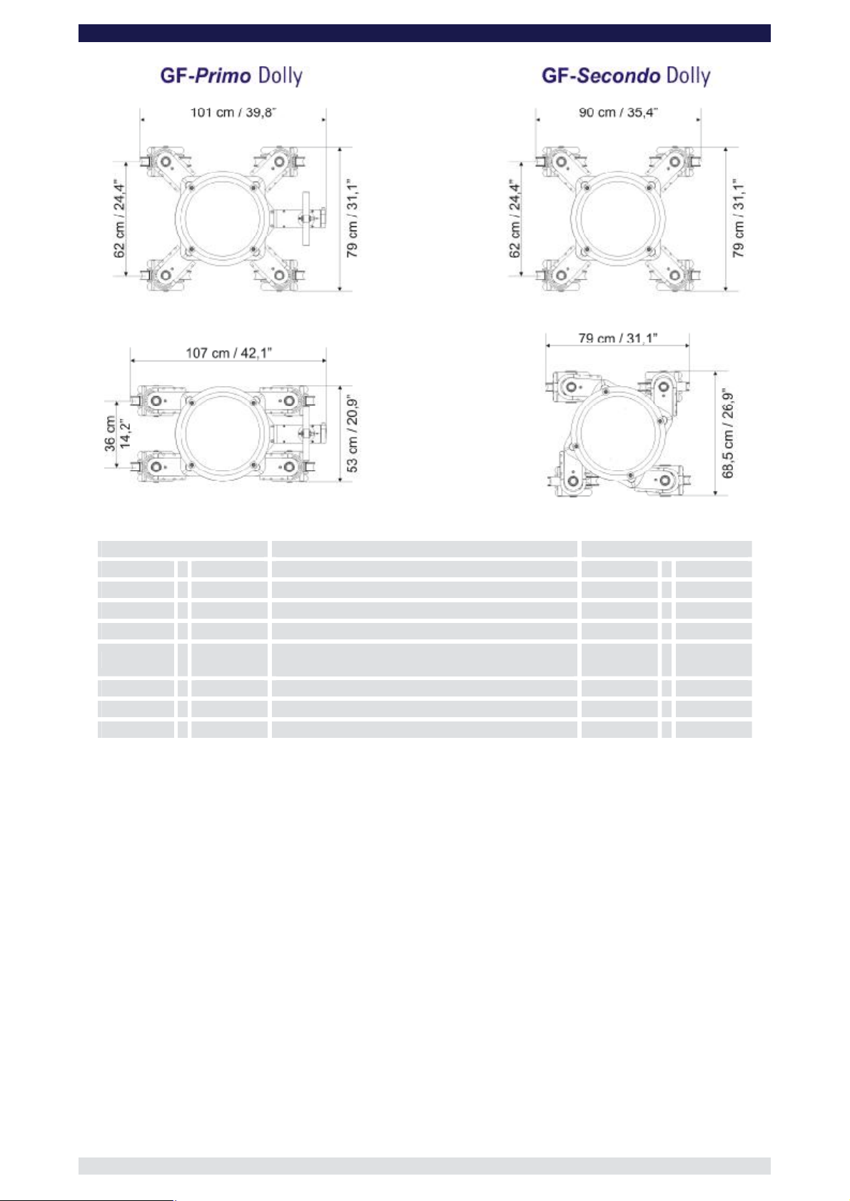
Technical Specs for GF-Primo - / GF-Secondo Dolly
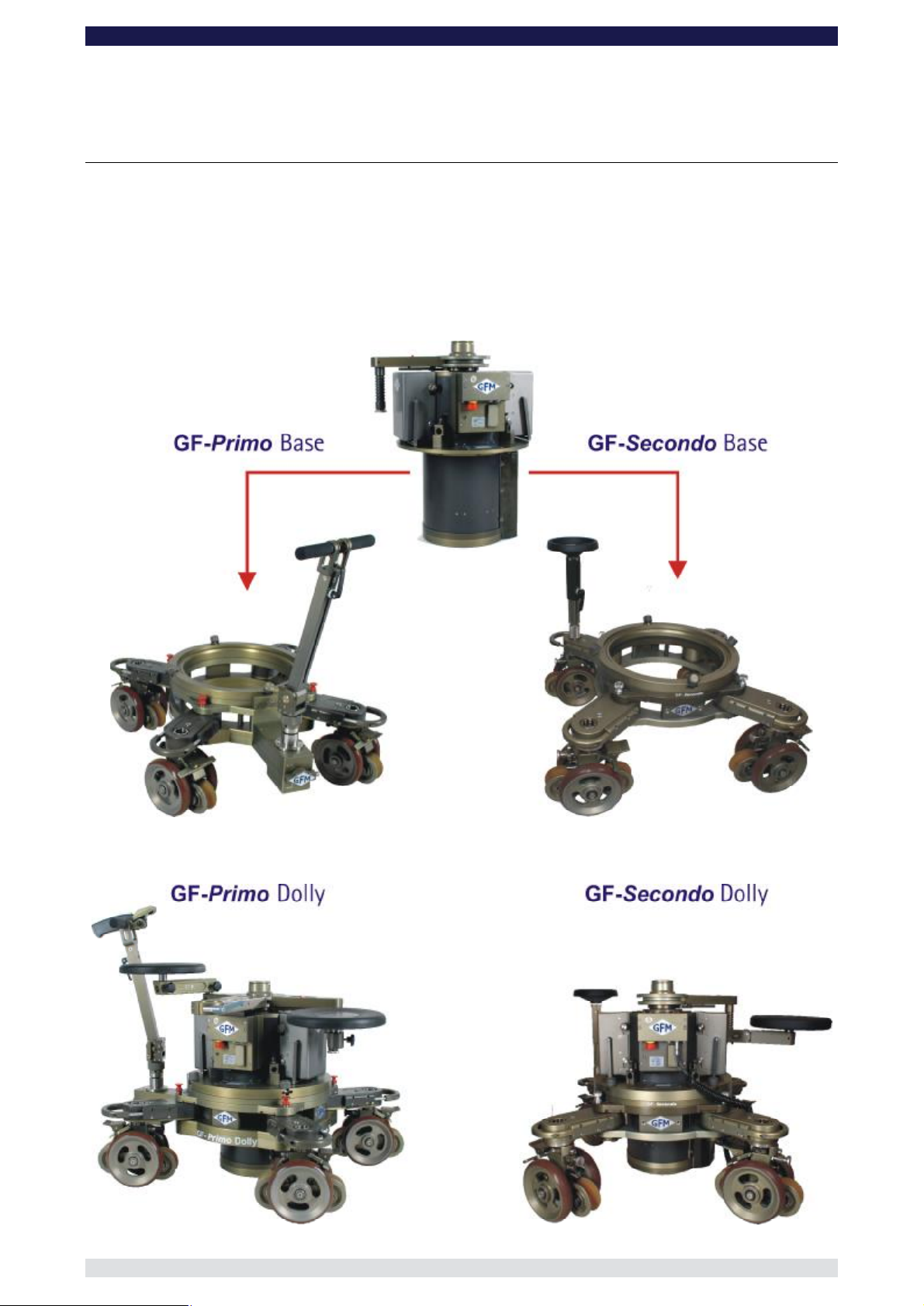
The difference between the GF-Primo - and GF-Secondo Dolly is effectively the different
base dollies. The columns are identical.
The GF-Primo Base has a central "one touch" selector allowing for immediate, one
handed, switch over to crab, front or rear wheel steering. GF-Secondo Base Dolly can
also switch from crab, front or rear wheel steering but to do so, each wheel must be
adjusted individually. The GF-Secondo also has 2cm more ground clearance (column to
ground).
Page 6
GF-Primo / GF-Secondo Dolly System Instruction Manual
Page:
5
2,5 sec Duration of column lift 2,5 sec
0 – 70cm / 0 – 27“ Lift range 0 – 70cm / 0 – 27“
140cm /
70cm /
250kg / 550lbs Maximum column lift capacity 250kg / 550lbs
900kg / 1980lbs
80kg / 176lbs Transport weight Dolly Base 69kg / 151lbs
68kg / 149lbs Transport weight column without batteries 68kg / 149lbs
54“ Maximin column height 142cm /
27“ Minimum column height 72cm /
Maximum column load capacity when fully
retracted (column movement not allowed)
900kg / 1980lbs
55“
28“
Page 7
GF-Primo / GF-Secondo Dolly System Instruction Manual
Page:
6
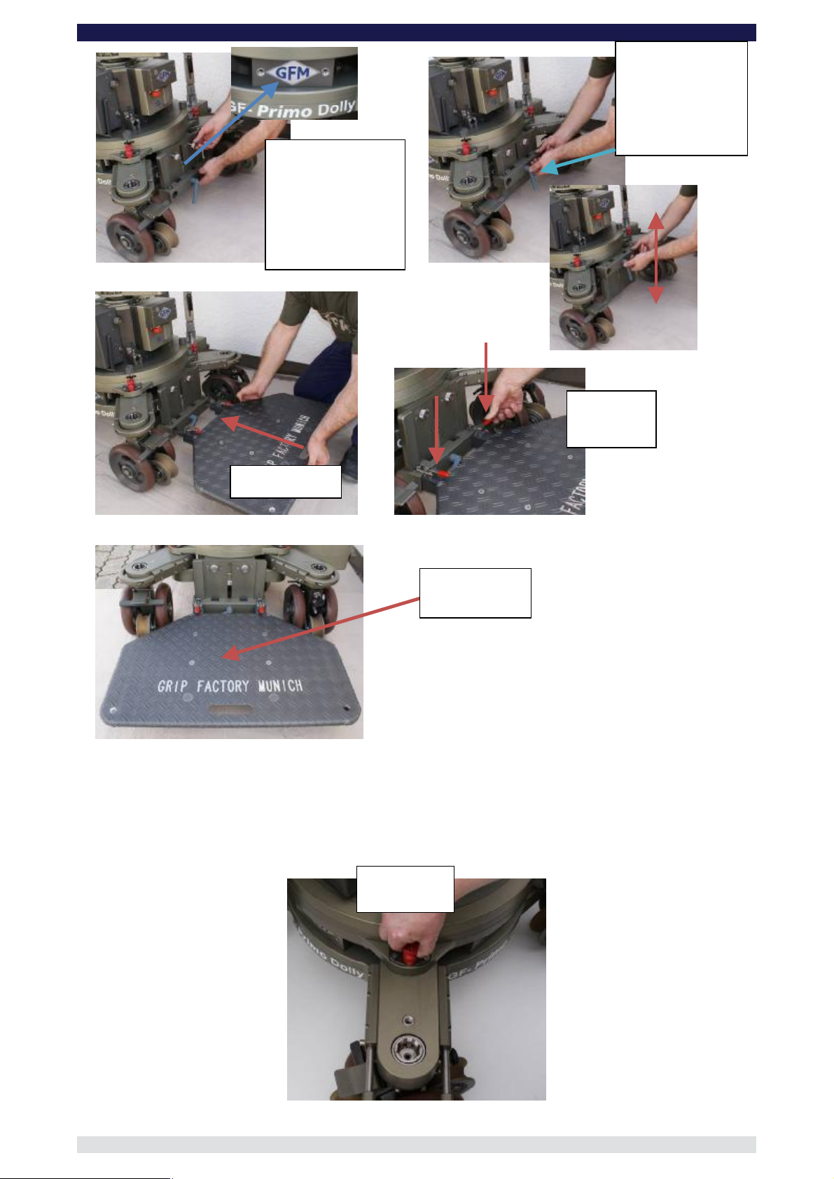
handle double
functions as a lock for
the platforms. Extend the
handle by pressing the
stainless steel button on
the left side of the wheel
arm. At the same time
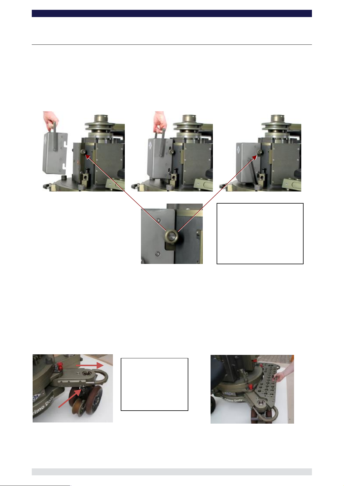
The Base Dolly
Changing the batteries
The dolly’s’s batteries are connected to the column with a user friendly “drop & go” system.
The column requires 2 x 24Volt Battery units to function.
Centre the battery over the locking mount. Move the battery into position and drop it gently
onto the locking shaft.
Locking shaft & knob
Open the left and right
locking knob to mount the
battery. When in place,
hand tighten the knobs to
secure the battery.
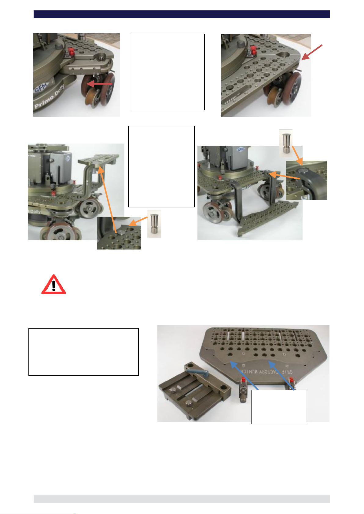
Connecting the Platforms
The Standard Multifunctional Platform Set
The platform set consists of 4 units. Each platform is machined to provide a selection of
threaded (10mm & 3/8”) and non-threaded holes (12, 25 & 28mm).
3 of the units are identical and fit on any of the 3 sides of the dolly. The 4th unit is
machined slightly differently and fits only on the side of the dolly where the steering
gearbox is located.
The carry
pull the handle out.
Page 8
GF-Primo / GF-Secondo Dolly System Instruction Manual
Page:
7
By using seat arm
extensions the
standard platforms can
also be combined to
form steps and low
Special “drop in” pins
are required. The pins
are inserted from top
to bottom and securely
bolted on the bottom
joint.
Attach the required
mber of platforms. To
secure them, press the
stainless steel button and
push the handle towards
the dolly. When the handle
is engaged in the locked
position you will hear an
audible click and the
button will be extended i.e.
unctional Hi/low
Platform can be dismantled by
unscrewing 2 bolts, allowing the
wider platform part to be mounted on
the base dolly as described on the
Remove the 2
locking bolts to
dismantle the
nu
not flush with arm.
platforms.
Attention: When using the platforms ensure that they are mounted and fitted
correctly. The platform must fit snuggly to the dolly frame with no gap
inbetween. Ensure that the steel pin on the locking handle is engaged
correctly as described above i.e. the steel pin must be visible!
Mounting the Low Platform System
The 2 part Multif
previous page
platform
Page 9
GF-Primo / GF-Secondo Dolly System Instruction Manual
Page:
8
The mounting plate
can be bolted to the
dolly chassis on 3
sides. It self centres
secured with
2 x M10 bolts that
should be tightened
The height of the
platform mount can
be adjusted and
secured with the
grey locking lever.
Hand tighten
Max. payload
Attach
both snap
ull to open
securely.
and is
securely by hand.
locks
Insert platform
100kg / 220lbs
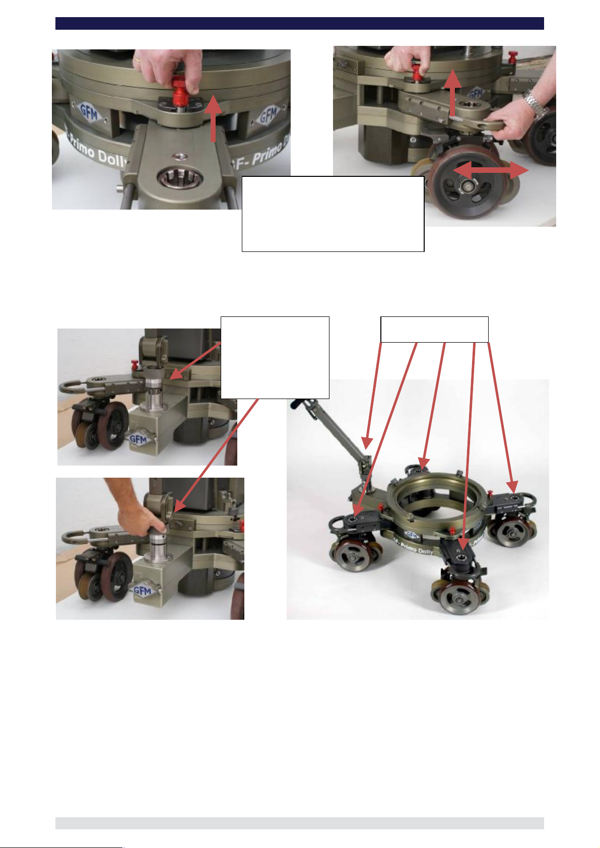
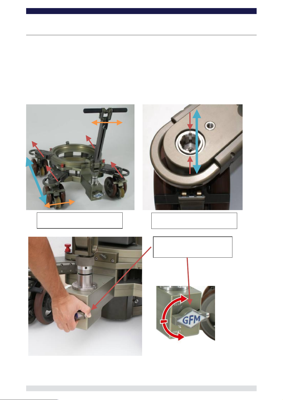
Wheel arm adjustment
Each of the 4 wheel arms has an individual locking mechanism to secure the position of
the wheel arms and ensure a stable, no-play base. To adjust the wheel arms to change
from, for example, standard to narrow gauge note the following.
P
position
Page 10
GF-Primo / GF-Secondo Dolly System Instruction Manual
Page:
9
Hold the locking pin in the released
position and at the same time adjust the
wheel arm to required position.
When in position ensure that the locking
Insert the steering
handle into one of the
ns.
To reduce play, hand
tighten by turning the
locking sleeve
is fully inserted.
Connecting the Steering Handle:
The Steering Handle can be attached to each of the 4 wheel arms on the GF-Secondo as
well as the central steering gearbox on the GF-Primo.
5 steering positio
clockwise.
5 steering positions.
Page 11
GF-Primo / GF-Secondo Dolly System Instruction Manual
Page:
10
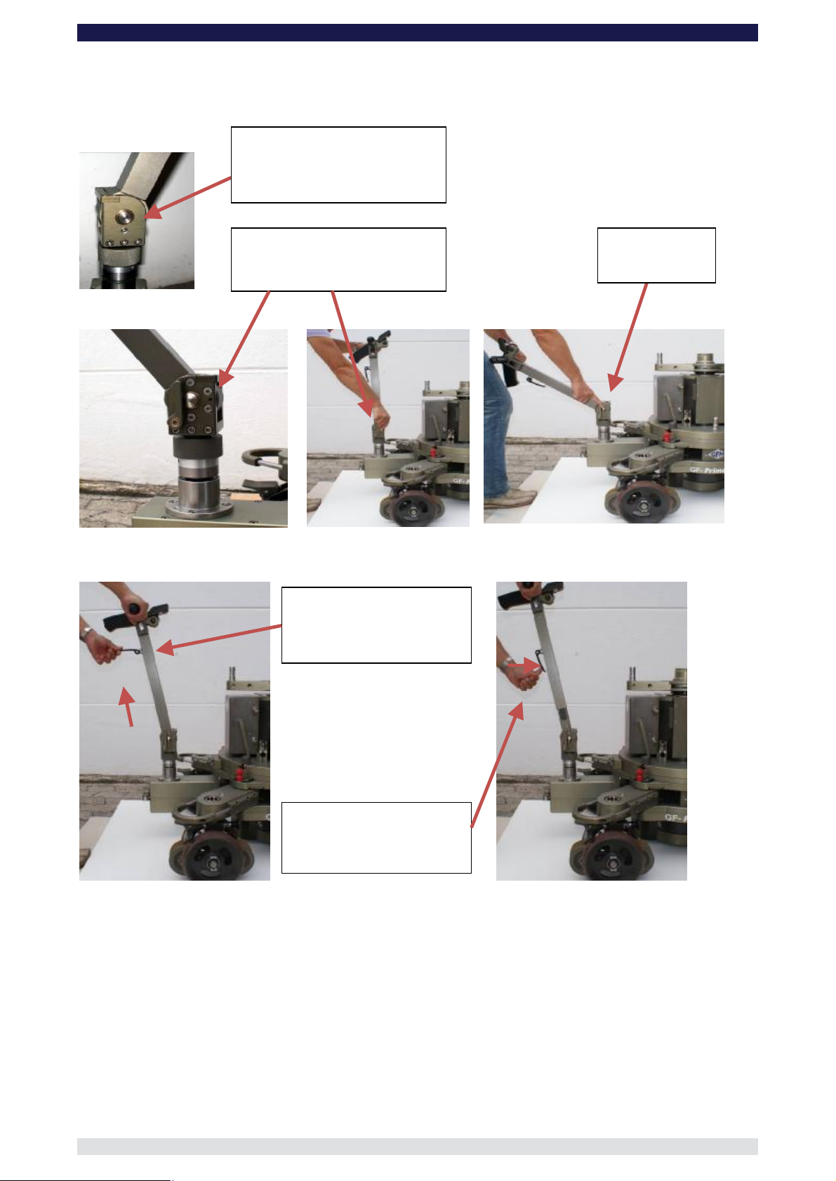
Release lever.
Push forward to
adjust angle and activate stepless
Release lever.
Pull back to set
angle
Drag adjustment:
se in
stepless angle mode i.e. release
To adjust the length of the
steering handle, open the
release handle and adjust to
When the steering handle is
in position, close the release
Adjusting the angle of the Steering Handle:
The GF-Primo’s Steering Handle offers individual height and angle settings. The angle can
be set as follows:
Tighten or loosen for u
lever pushed forward.
angle mode
Adjusting the length of the Steering Handle:
required height.
handle.
Page 12

Page:
11
Connecting the HCU to Steering Handle
e
locking pin and
insert the HCU
rosette into the
matching cradle.
Push the HCU
down so it fits
snugly in the cradle.
Adjust the angle as
When not in
use, fold in
To use, fold
down the
Insert the
HCU into
Hand Control Unit Rest:
Locking pin
the HCU rest.
GF-Primo / GF-Secondo Dolly System Instruction Manual
Pull back th
required.
HCU rest.
the rest.
Page 13
GF-Primo / GF-Secondo Dolly System Instruction Manual
Page:
12
Press steel release pin and
wheels
rrect positioning of the steering
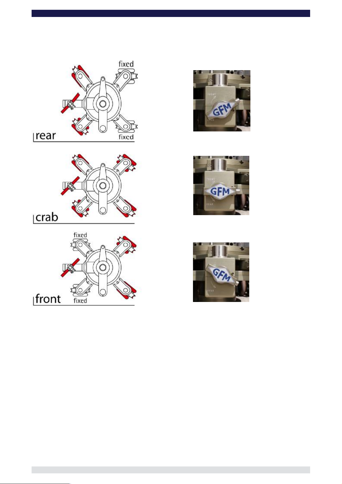
GF-Primo Steering modes:
To change from one steering mode to another first of all ensure that all 4 Combi-wheels
are pointing in a straight line as seen from the rear of the dolly
In each of the 4 steering rod mounts you will see 2 notches machined into each rim. The
notches should be in line with the actual gearbox. On the steering mount on the GF-Primo
gearbox you will also find the same markings and these should also be in alignment with
the gearbox. It is only possible to change steering mode when the wheels are aligned in
this starting position. If the wheels are out of position they must be reset as described
below.
Positioning of the Combiand steering rod mount
Co
rod mount and Combi-wheel
turn the selector
Wechsel des Lenkmodus
Steering mode selection
Page 14
GF-Primo / GF-Secondo Dolly System Instruction Manual
Page:
13
GF-Primo‘s 3 steering modes and selector position:
Page 15

GF-Primo / GF-Secondo Dolly System Instruction Manual
Page:
14
SP1
-
Selector switch pointing
= wheel not turnable
SP2
-
Selector switch pointing side
SP3
- Selector switch pointing
downwards: Disconnected from
steering = wheel rotates freely i.e. on
GF-Secondo Steering modes:
Each of the 4 combi-wheels has an individual selector switch which enables each wheel to
be fixed, connected or disconnected from the steering mechanism:
Switch position SP 1 ⇒ Combi-wheel in fixed position
Switch position SP 2 ⇒ Combi-wheel steerable
Switch position SP 3 ⇒ Combi-wheel in free rotate
Attention: To change steering mode the top and bottom red
markers must be aligned!
Tip: Regardless of selected mode, the GF-Secondo Dolly can
be steered from any of the 4 steering points at any time.
upwards: wheel in fixed position
wards: Connected to steering
= wheel is steerable
Page 16

GF-Primo / GF-Secondo Dolly System Instruction Manual
Page:
15
GF-Secondo’s three steering modes and their selector positions:
Page 17

GF-Primo / GF-Secondo Dolly System Instruction Manual
Page:
16
Combined Studio &
Track wheel brake
Kick down to lock the
Studio & Track wheel
To disengage the wheels from
the steering e.g. use on curved
track, simply pull out the locking
Locking pin
to
wheel
wheels
from the base, firstly disengage
the wheel from the steering and
then pull the lower smaller
Note: To remove the wheel the
dolly must either be jacked up or
turned upside down. If jacked
p, hold the wheel securely
when pulling the locking pin as
the wheel will drop.
Combi-Wheels – GF-Primo & GF-Secondo:
Combi-wheel Brake
Each Combi-wheel has a kick down brake for the studio /pneumatic wheels. The 2 Combiwheels at the rear of the dolly also have integrated track wheel brakes attached to the
standard wheel brake.
on rear 2 wheels.
brake.
Disconnecting the wheels from the steering:
for steering
Locking pin
remove Combi-
To remove the Combi-
locking pin out.
u
pin and turn 90°
Page 18

GF-Primo / GF-Secondo Dolly System Instruction Manual
Page:
17
When driving onto track using a drive
e that the track wheel brakes
wheels are at the rear of
the wheel as it goes onto the track. If not
the brake will engage and stop the dolly
Track wheel
brakes at the rear
Locking pin to
wheel
Selector switch
pointing downwards:
Disconnected from
steering = wheel
Dolly set the selector switch at position SP3. Then pull
the Locking Pin to remove the wheel unit by moving it downwards. Remove carefully and with caution! Hold the
wheel securely so it doesn’t drop off!!
wheels either support the base from underneath allowing sufficient
clearance to remove the wheel. Alternatively, turn the base upside down and lift the wheel off. Remove carefully
Disconnecting the GF-Secondo Combi-wheel from the steering and
removing the Combi-wheel unit
To remove the GF-Secondo Combi-wheels from the Base-
Attention: Before removing the Combiand with caution!
rotates freely i.e. on
Position SP3
remove Combi-
Going on Track:
ramp, ensur
on the Combi-
from moving.
Page 19

GF-Primo / GF-Secondo Dolly System Instruction Manual
Page:
18
Attach the bracket and
3 x
Turnstile Brake:
Push towards
centre to open, pull
towards seat to
Seat adjustment:
Pull towards seat to
open. Push
towards centre to
lock.
Collision protection:
Seat arm moves
upwards in the event
The Multifunctional Turnstile Mount:
A maximum of 4 brackets can be attached to the turnstile mount. The adjustable seat arm
mount is not removable.
secure tightly with
M8 bolts.
lock.
of a collision.
Page 20

GF-Primo / GF-Secondo Dolly System Instruction Manual
Page:
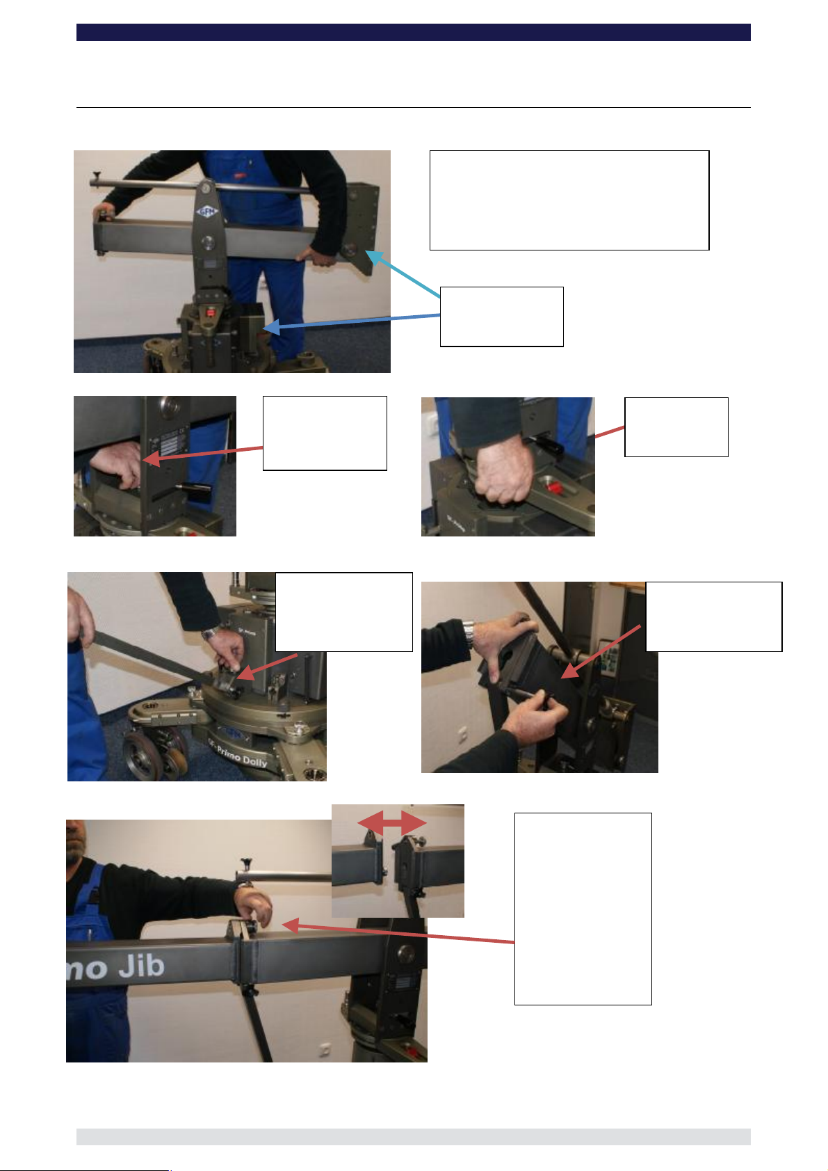
19
lifting
position with carry
bars pointing down.
Remove the column
To remove the carry
bars release the
locking pin and pull
out.
Insert the 4 carry
bars ensuring that
the locking pin are
the 4 column
locking nuts and tilt
Removing the Column with the Carry Bars:
engaged fully.
Alternative
E.g. stairs
Open
them back.
carefully by lifting.
2 persons!
Page 21

GF-Primo / GF-Secondo Dolly System Instruction Manual
Page:
20
e Selector
Hand Control
Hand Control Unit Components
The following describes the individual button functions and components on the Hand Cotrol Unit.
On/Off (emergency Off button)
Status-LED
Channel Selector
Display
RMP-Button
MARK / LIMIT-Button
Radio signal sender
Handle Rosette
SPD-Button
Rocker Switch
Programm and Mod
Button
Connector for
Hand Control
Cable
Battery for
HCU Battery Lock
Unit
Page 22

GF-Primo / GF-Secondo Dolly System Instruction Manual
Page:
21
Electronic Unit Components
The following describes the electronic components:
Emergency Off Switch!
Press to deactivate
electronic!
Must be extended to
allow operation!!
On- / Off-Switch with Status-LED
Connectors for Hand Control Cable
Cover for Back Up Drive System Channel Selector
Getting started
In general, when the dolly arrives from the factory it will be set up to be switched on in either
Wireless Mode or with Cable connection.
To switch on the dolly requires the following:
In Wireless mode: Dolly batteries must be charged and connected correctly (see page 7)
Electronic and HCU must be on the same channel (see page 23)
HCU battery is charged and inserted into the HCU
The Emergency Switch must be off i.e. switch extended (see page 23)
In Cable mode: Dolly batteries must be charged and connected correctly (see page 7)
Electronic and HCU must be connected via cable (see page 25)
The Emergency Switch must be off i.e. switch extended (see page 23)
Starting off
In wireless mode: Check that Electronic and HCU are on the same channel.
Turn dial to select
channel
Page 23

GF-Primo / GF-Secondo Dolly System Instruction Manual
Page:
22
Switch on by first pressing the On/Off Switch on main electronic housing. Wait a few seconds until the
LED on the switch starts blinking red/green, then press the On/Off button on the HCU. The display will turn
red, then blue. The column is on.
LED off
Display off
In cable mode: Switch on by pressing the On/Off button on the HCU. The display will turn red, then blue. The
column is on.
Note: Check to make sure the Emergency OFF Switch is not active. It should be extended, not
pushed in.
LED red
Display red
LED green / red
blinking (ready)
Display blue (ready)
Page 24

GF-Primo / GF-Secondo Dolly System Instruction Manual
Page:
23
Column scale/ position shown in
RMP = Ramp (sets strength of
acceleration and deceleration of
SPD = Speed (sets speed of
columns travel: slow
→
00;
To connect the cable from the HCU to Electronic:
Cable connection
Marking Fischer
Plug
Hand Control Unit Display
Selected User = U1
There is a choice of 4 users.
U1 to U4,
column: hard→00; soft→22)
HCU Mode: N=Normal,
E=Enter, M=Markers
Column height / position
Voltage of columns batteries
mm (also available in ft or %)
Motor temperature in °Celsius
Limit to restrict the columns lift range
(e.g. from 200mm – 500mm)
HCU Battery status
Page 25

GF-Primo / GF-Secondo Dolly System Instruction Manual
Page:
24
Adjusting the Speed or Ramp
To adjust the speed or ramp press and hold the respective button and press the Rocker
Switch up or down to adjust and select the required speed or ramp
Adjusting the Ramp
Adjusting the speed
Generating Movement
For standard work situations where it is required to just move the column up and down and vary speed and
drive ramps, the HCU should be set on either of the 4 Users and the HCU mode N=Normal should be
selected.
To select the HCU Mode
On the underside of the HCU is the HCU Mode Selector Button. Simply press to
scroll through and select the required mode.
Mode N=Normal
HCU Mode selector
button. Press to
Mode E=Enter Mode M=Marker
Mode Selector
Page 26

Page:
25
Setting a new lower and upper limit
Select N Mode. Position the column at the new lower position e.g. 200. Press the blue LIMIT Button
on the HCU and hold it. Using the Rocker switch drive the column to the new upper position e.g.500.
Release the Limit Button. The column will now remain within the range of 200 to 500.
To cancel the limits press the LIMIT Button
GF-Primo / GF-Secondo Dolly System Instruction Manual
Setting new lower and
upper LIMIT´s
The HCU Modes
Mode NORMAL N ⇒ offers standard movement with selection of speeds and ramps. Lower and
upper limits can be set.
Mode ENTER E ⇒ Entering, editing, deleting and replacing 6 Markers. Setting up the shot.
Mode MARKER M. ⇒ Replaying the shot with variable speeds and ramps. Allows you to manually
drive the column from Marker to Marker.
Mode N
Mode E
Mode M
Page 27

GF-Primo / GF-Secondo Dolly System Instruction Manual
Page:
26
Button to add or over write
Button to delete set
Currently selected or next
Button to select set or to
Mode ENTER “E”
MARKER
ADDMARKER‘s
Explanation of the individual display symbols:
CLRMARKER’s
Already set MARKER‘s
MARKbe set MARKER‘s
Currently selected MARKER:
Indicates the selected MARKER that can be set, over written or deleted.
Already set MARKER:
MARKERs which have already been set are shown beside the lift range display.
MARK-Button:
With the MARK-Button already set MARKERs can be selected and then with the ADD or
CLR buttons be over written or deleted.
CLR-Taste:
With the CLR-Button already set MARKERs can be deleted.
ADD-Taste:
With the ADD-Button MARKERs can be set or over written.
Setting individually adjustable MARKERs
Page 28

GF-Primo / GF-Secondo Dolly System Instruction Manual
Page:
27
To set MARKERs, Mode E must be selected.
Setting MARKERs in a numerical sequence:
Press the MARK-Button until the digit 1 shows on the display as the currently
selected MARKER.
By using the Rocker Switch drive the column to the required height and stop in this
position.
Now press the ADD-Button, to allocate MARKER 1 to this position.
The digit 2 will show on the display as the next MARKER that can be set.
Again, by using the Rocker Switch drive the column to the required height and stop
in the required next position.
Now press the ADD-Button again to allocate MARKER 2 to this position.
MARKERs 3 to 6 can be selected in the same manner.
Setting MARKERs
Page 29

GF-Primo / GF-Secondo Dolly System Instruction Manual
Page:
28
Over writing MARKERs:
Already set MARKERs can be over written as follows:
By pressing the MARK-Button, select the MARKER number you want to over write
e.g. MARK 1 (Height 200 mm)
By using the Rocker Switch drive the column to the new required height e.g. 250mm
Now press the ADD-Button to reset the MARKER 1 from 200mm to 250mm.
Over writting the set
MARKER
Deleting MARKERs:
To delete set MARKERs proceed as follows:
By pressing the MARK-Button select the number of the MARKER you want to
delete, e.g. MARKER 4.
To delete the selected MARKER, press the CLR-Button.
Deleting MARKERs
Note: The deleted MARKER doesn’t necessarily have to be reset. The
software recognizes the digit is missing and will allocate the next
consecutive MARKER, in this case from 3 to 5.
Page 30

GF-Primo / GF-Secondo Dolly System Instruction Manual
Page:
29
Column scale/ position shown in
MP = Ramp (sets strength of
acceleration and deceleration of
column: hard
→
00; soft
→
22)
SPD = Speed (sets speed of
columns travel: slow
→
00;
There is a choice of 4 users.
Mode NORMAL N
In N-Mode the column can be driven in the selected Ramp RMP and Speed SPD. (To set RMP and SPD see
page 18, Adjusting the Speed or Ramp).
The complete lift range of the column can be used or based on individual requirements the
lift range can be restricted by setting a lower and /or upper limit with the LIMIT-Button.
The following picture shows the display in Normal Mode N upon activation:
Selected User = U1
R
U1 to U4,
HCU Mode: N=Normal,
E=Enter, M=Markers
Column height / position
Voltage of columns batteries
mm (also available in ft or %)
Motor temperature in
°Celsius
Limit to restrict the columns lift range
(e.g. from 200mm – 500mm)
HCU Battery status
Page 31

GF-Primo / GF-Secondo Dolly System Instruction Manual
Page:
30
Explanation of the individual display symbols as :
Selected User:
The HCU offers a choice of 4 individual Users ⇒ U1, U2, U3, U4. In each of the 4 Users, settings such as
RMP, SPD, set Limits as well as Markers can be entered and recalled.
HCU Mode:
This shows the current operational mode for the column. There are 3 Modes available, Mode N = Normal, E
= Enter and M = Marker. The letter of the selected mode is high-lighted in black when operational.
Attention: Should none of the Mode letters be activated press the HCU Mode selector
button found on the bottom / underside of the HCU.
Column height / position:
The lift range of the column is shown in 2 ways. One method is the vertical bar display (the higher the bar,
the higher the column). The other is the digital numerical display showing in mm, imperial or %. The columns
range is 0 to 705mm.
Column Batteries Voltage:
This shows the voltage of the respective battery. By standing in front of the electronic housing and looking at
the HCU display, the battery on the left hand side of the display represents the battery on the left side of the
column. In turn the battery on the right hand side of the display represents the battery on the right of the
column.
Note: A fully loaded battery will show approximately 26 Volts. During use the voltage will naturally
become lower so that after approximately 200 lifts the voltage will drop below 20 Volts (when
the column is moving).
When a battery drops below 19 Volt the HCU display as well as the respective battery
symbol will flash in red. This signals that the battery needs to be changed and charged.
Should the battery voltage drop below 17 Volt the column will automatically switch off and
the display will show „DOLLY BATTERY LOW“.
Attention To ensure the best performance it is advised to use fully charged batteries. When the
voltage is under 19 Volts a performance drop can be expected.
Motor temperature:
The motor temperature is also shown on the display. It should be noted the temperature shown is that of the
outside of the motor in its isolated housing and not the ambient air temperature
Note: A safety guard is installed to protect the motor from thermal overload:
If, during operation, the motor temperature exceeds 55°C the HCU display will flash red and
Battery identification
Page 32

GF-Primo / GF-Secondo Dolly System Instruction Manual
Page:
31
the temperature digits will also blink. This signals the movement of the column must be
reduced or stopped. Upon reaching a temperature of 60°C the column will automatically
switch off and the display will show „MOTOR TEMPERATURE HIGH“.
Tip: To protect and ensure a long lifespan for the motor temperatures above 55°C should be
avoided.
Should a temperature of 55°C be exceeded, reduce or stop column movements for 30 to 60
minutes to allow the motor to cool down.
Attention: Over heating of the motor can be caused by over loading the column or driving the column
without load.
Note: During operation the generated heat by the electricity flow is at its highest in the centre of the
motor and spreads to the outside housing. The temperature is measured on the outside of
the motor which can be up to 30°C lower than the inner kern of the motor. Therefore by an
over load of the motor at 60°C it must be shut down as with an inner temperature of 100°C
permanent damage can be caused.
Limit:
LIMIT allows the operator to restrict the columns lift range by resetting the lower and / or upper end stops.
The lift range can be changed from its standard 0 to 705mm to, for example, 200 to 500mm. When reset, the
column can only be moved within the new range until it is or due to a Mode change the column is in a
position outside the new LIMIT range
Hand Control Unit HCU Battery Display:
In wireless mode the HCU is energized with its own battery and not with the columns batteries. The HCU
battery is inserted into the rear of the HCU. The voltage status of the battery is shown on the HCU display as
a battery symbol.
Ramp and Speed:
The columns speed and drive ramp may be adjusted in grades of 23 levels:
Speed Slow → Level 00 Fast → Level 22
Rampe Hard → Level 00 Soft → Level 22
(Longer acceleration and deceleration)
Page 33

GF-Primo / GF-Secondo Dolly System Instruction Manual
Page:
32
ct required
Currently recorded or set
Mode MARKER M
In M-Mode it is possible to activate the recorded MARKERS. Between each MARKER it is
possible to vary direction, speed, and alter the ramp. Upon reaching each of the 6
MARKERS the column will stop automatically.
Explanation of the individual display symbols:
Set MARKERs:
MARKERs that have already been set or recorded are graphically shown beside the lift
range bar on the display.
Current column position and lift range:
The current column position and driven lift range are shown on the lift range bar display.
The available lift range between 2 positions will also be displayed. When MARKERs are
set, the bar display will indicate the available lift range between the MARKERs.
MARK-Button to select required MARKER:
With the MARK-Button it is possible to select the next required MARKER and if needed,
more than one MARKER can be skipped.
Working in M-Mode
In M-Mode up to 6 individually recorded positions called MARKERS can be utilized to
construct the required shot.
The following explains the operation in MARKER-Modus:
After recording the required MARKERs in E-Mode switch to M Mode by pressing the
Program and Mode Selector Button on the underside of the HCU.
Lift range bar display
MARKERs
Current position and lift range
MARK-Button to sele
MARKER
Page 34

GF-Primo / GF-Secondo Dolly System Instruction Manual
Page:
33
Settings such as Speed and Ramp are accessible and even different Speeds and
Ramps can be selected between the various positions.
Tip: In between the various MARKERS it is possible to make manual
moves and to control the speed by pressing the Rocker Switch, more
or less to go faster or slower.
By using the Rocker Switch drive to the first MARKER, with the lowest, flashing
digit, e.g. MARKER 1.
Note: After changing to Mode M, the lowest numerical digit will be suggested
as the first MARKER and will blink. As soon as the first position is
reached, the second or next MARKER will be indicated through
flashing and the lift range between these 2 positions will be set.
Attention: By pressing the MARK Button you can select other MARKERs as the
next position.
Selecting MARKERs
Press the MARK Button and use the Rocker Switch to move to the flashing digit /
MARKER.
Tip: The present height is shown on the display with the numerical display
and on the other hand with the shaded vertical bar display. The
direction of the next position is visible.
The column can now be driven in the selected Speed and Ramp and upon reaching
the MARKER it will stop automatically. The next MARKER can recognised as the
respective digit will blink and the vertical height bar will show the new lift range.
Tip: As long as the next MARKER is not reached, movement between the
2 respective MARKERS is not restricted so direction or speed changes
are possible.
Page 35

GF-Primo / GF-Secondo Dolly System Instruction Manual
Page:
34
Emergency Operation of the Column
The GF-Primo Dolly’s electronic is equipped with a back-up systems to enable movement
of the column in an emergency situation.
Emergency situations are:
o Defective or non-functioning electronic (HCU cannot operate the electronic)
o Defective or lost HCU
Attention: Emergency operation is not for working with! Using the column with a under
load with mounted camera or camera operators is not allowed!
Attention: As soon as the emergency switch is activated the column moves with a
preset speed and NO Ramp. Ensure that no equipment or persons are on the
column. Jib arms etc must be dismantled prior to activation of the emergency
switch. Working in emergency mode is not allowed!
To activate the emergency mode proceed as follows:
Using a 2.5mm Allen Key, remove the cover of the emergency switch by
unscrewing the 4 bolts.
Upon removing the cover, 3 multi-point connectors are visible whereby there is a
plug inserted in the top connector. For normal operation the plug must be inserted
into the top connector!
Emergency Switch Cover Connector for normal operation
Page 36

GF-Primo / GF-Secondo Dolly System Instruction Manual
Page:
35
In emergency mode, if the column needs to be moved
§ upwards, insert the plug in the middle connector.
§ downwards, insert the plug in the lower connector.
Attention: When inserting the plug do not clamp or jam any cables!
Note: The plug has an anti-twist protection and inserts in one direction only.
Press the hidden emergency button found in the round hole at the bottom of the 3
connectors. The column will move in the respective direction according to where the
plug is positioned.
Plug for upward emergency mode
Plug for downward emergency mode
Attention: When replacing the cover ensure that the emergency plug is inserted into the top
connector as the cover cannot be mounted if the plug is in another position.
Page 37

GF-Primo / GF-Secondo Dolly System Instruction Manual
Page:
36
Cable connection from HCU
alignment marking
button
Synchronizing the Hand Control Unit and Column
In general, when delivered, the electronic and HCU will already be synchronized and both units will be
selected to the same channel to ensure that wireless mode can be used.
If however, the HCU or electronic unit are replaced, the new unit must be synchronized with the original
opposite unit i.e. if the HCU is replaced it must be synchronized with the original electronic.
Attention: In wireless mode, only 1 HCU unit can be synchronized with the electronic at any one time.
To use a different HCU requires it to be firstly synchronized! To revert back to the first HCU
requires it to be re-synchronized.
Connect the HCU to the electronic with the cable and switch on the column using the On/Off switch (red
button) on HCU.
Tip: When connecting the Fischer Plug align the red dots
Display off.
Press „On“
Cable connection
to Column
Note the
on Fischer Plugs
Red dots
After pressing the
„On“ button the
display turns red
Display blue (ready)
Page 38

Page:
37
Calibrating the column
The column will need to be calibrated :
o After a service or repair
o After a software update
o After the column is crashed / driven against an object / hit the mechanical top or bottom of
column lift range
o After using emergency switch
Calibration procedure
Press and hold the SPD-button, then switch the column / HCU on. As soon as the HCU LED is on
the SPD-button can be released.
The Display shows „CAL DOLLY CONTROL“.
Press the CAL button (RMP) button to begin.
The column will automatically drive to its lowest position and then to the maximum height. Upon
reaching the maximum height press EXIT.
Press SPD and On.
Then press CAL to
begin
GF-Primo / GF-Secondo Dolly System Instruction Manual
Page 39

GF-Primo / GF-Secondo Dolly System Instruction Manual
Page:
38
Trouble Shooting
The following describes some possible errors and the solutions to correct the errors.
Error:
Dolly and HCU are not functioning in wireless mode
Solution:
Check
o Are the HCU and column equipped with wireless modules?
o Is the emergency OFF Switch inserted into the off position? If so, twist clockwise
to deactivate.
o If the HCU battery is in place. The wireless mode does not work without battery.
o Are the HCU and electronic synchronized? If not, connect via the HCU cable.
o Are both the HCU and electronic sending and receiving on the same channel?
Error:
In wireless mode there is a disturbance in the movement of the column.
Solution:
Select the next or any other channel e.g. 4.
If this doesn’t help, change to cable operation.
Check the battery voltage with a loaded column. Should the voltage fall below 19V replace
or charge the batteries.
Check the motor temperature. In general terms the following can be said about the electromotor:
The hotter the motor becomes, the higher the performance loss. Should the motor reach a temperature of
60°C the column will shut down automatically to avoid permanent damage. However, it is suggested to avoid
use of the column when the temperature exceeds 50°C.
If the above solutions do not result in an improvement of the columns performance please service the
column (see “servicing the column”).
Error:
Disturbance of movement during cable operation.
Solution:
Check the battery voltage with a loaded column whilst moving up and down. Should the
voltage fall below 19V replace or charge the batteries.
Check the motor temperature. In general terms the following can be said about the electromotor:
The hotter the motor becomes, the higher the performance loss. Should the motor reach a temperature of
60°C the column will shut down automatically to avoid permanent damage. However, it is suggested to avoid
use of the column when the temperature exceeds 50°C.
If the above solutions do not result in an improvement of the columns performance please service the
column (see “servicing the column”).
Page 40

GF-Primo / GF-Secondo Dolly System Instruction Manual
Page:
39
Error:
It’s not possible to switch on the electronic / column.
Solution:
Is the emergency OFF Switch inserted into the off position? If so, twist clockwise to
deactivate.
Check that the batteries are charged and connected correctly to the column.
Remove the batteries from the column and check the battery poles on the column. They
should be sticking out from the connection plate and not flush with it. Reconnect the
batteries and check the connection. The top of the battery housing should be flush with the
column.
If the electronic was removed, double check to make sure it is connected correctly. The
electronic housing must be flush with the connection plate on the column.
Concerning operational mode:
Wireless mode:
Press the on switch on the electronic for approx. 5 seconds.
In wireless mode always activate the electronic, then the HCU.
In wireless mode the HCU and electronic must have been synchronized prior
to use. Synchronization must take place when the HCU is exchanged or
replaced. (see „4.1 Synchronizing the HCU and Column on page 8)
Cable mode:
The column can be switched on directly with the HCU.
Error:
The HCU cannot be switched on or keeps switching itself off (although the electronic is
switched on):
Solution:
Check the operational mode!
In wireless mode:
Check if
o the electronic is switched on. In wireless mode it must be switched on first.
o the emergency OFF Switch is inserted into the off position. If so, twist clockwise
to deactivate.
o the HCU is equipped for wireless operation and not that it’s only equipped for
cable operation.
o the HCU battery is in place. The wireless mode does not work without battery.
o both the HCU and electronic are sending and receiving on the same channel.
Before operating the column and the HCU for the first time it is necessary to synchronize
both units.
Cable mode:
Check if
o the emergency OFF Switch is inserted into the off position. If so, twist
clockwise to deactivate.
o the cable is connected correctly.
o the connectors are damaged (broken or bent pin).
o the same problem occurs with a different cable.
Page 41

GF-Primo / GF-Secondo Dolly System Instruction Manual
Page:
40
Error:
Column and HCU don’t operate in cable mode.
Solution:
Check if
o the emergency OFF Switch is inserted into the off position. If so, twist
clockwise to deactivate.
o the cable is connected correctly.
o the connectors are damaged (broken or bent pin).
o the same problem occurs with a different cable.
o the battery poles on the column are extended and not flush with column.
o the batteries are charged.
Error:
The column cannot be calibrated.
Solution:
Check if
o the correct button combination is being pressed to activate the calibration mode
(see „4.2 “calibrating the column” on 10).
o the emergency OFF Switch is inserted into the off position. If so, twist clockwise
to deactivate.
o the batteries are charged.
Check the operational mode!
Wireless mode:
Check if
o the electronic is switched on. In wireless mode it must be switched on first.
o the HCU is equipped for wireless operation and not that it’s only equipped for
cable operation.
o the HCU battery is in place. The wireless mode does not work without battery.
o both the HCU and electronic were synchronized (see „4.1 Synchronizing the
HCU and Column on page 8 )and that they are sending and receiving on the
same channel.
If the above solutions do not result in an improvement change to cable mode and repeat the calibration
procedure.
Cable mode:
Check if
o the cable is connected correctly.
o the connectors are damaged (broken or bent pin).
o the same problem occurs with a different cable.
Error:
The calibration mode disrupts by itself during the procedure:
Solution:
Change from cable to wireless mode or vice versa, then try again.
Page 42

GF-Primo / GF-Secondo Dolly System Instruction Manual
Page:
41
Error:
Upon switching on the column an incorrect height is shown!
Solution:
Calibrate the column.
If this doesn’t solve the problem and the error is still present, repeat the procedure.
Error:
Display is red:
Solution:
If the display is red it can have a few reasons and in general it is not necessarily an error
but also a signal.
If the display turns red it can mean either
o the connection to the electronic is disrupted.
o the motor temperature is too high.
o the battery voltage is too low.
In these cases
o in wireless mode switch both units to the next higher channel and check if there
is contact between both units.
o Check the load on the column and stop operation to enable the motor to cool
down.
o exchange the batteries and recharge the used batteries.
Technical specifications are subject to change without notice!
Page 43
Page:
42
ASSEMBLING THE GF-Primo Jib:
Insert the l
ocking
pin to connect the
middle section to
Fit the connection
rod onto the steel
pin and hand
tighten the locking
Secure by
Secure the
locking bolt by
turning it into
adapter
Place the middle section of the GF
-
Primo
Note: the front of the jib should be
mounted on the same side as the
Jib front and
Connect the rear
section to the
middle section by
joining the key link
pin to the slot and
Hand tighten the
locking bolt and
secure by
tightening the
the Euro-
GF-Primo / GF-Secondo Dolly System Instruction Manual
Jib on to the column’s Euro-adapter.
electronic housing.
electronic
housing
pulling
locking lever
the rod.
dropping down.
locking lever.
Page 44

GF-Primo / GF-Secondo Dolly System Instruction Manual
Page:
43
The front plate of the
jib has 4 threaded
holes where the
mounting bolt is
inserted depending on
which platform
E.g. for low position.
Screw the mounting
bolt into the lower
Mount the High/Low
Rig onto the mounting
Attach the weight
triangle to the rear
of the arm by
aligning the hole
for the weight rod
over the respective
hole on the rear
arm and inserting
the weight rod.
Ensure that the
weight rod is the
me length on
Connect the
parallelogram rod into
the parallelogram rod
on the middle section
and secure with the
locking pin.
Connect the
parallelogram rod to
the parallelogram rod
on the weight triangle
and secure with the
locking pin.
sa
both sides.
position is required.
bolt
hole.
Page 45

Page:
44
To mount the
High/Low Rig in the
gh position move
the mounting bolt to
Inser
t the locking bolt
and secure with the
Change the position
of the mounting bolt
on the High/Low Rig
Mount the platform
and insert the locking
bolt and secure with
To mount the
High/Low Rig in the
high position move
the mounting bolt to
Mount the High/Low
Rig onto the mounting
bolt and push it
upwards until the
locking bolt is in line
Insert the locking bolt
and secure with the
hi
the high hole.
the high hole.
GF-Primo / GF-Secondo Dolly System Instruction Manual
locking lever.
to the low position
the locking lever.
with the hole.
locking lever.
Page 46

GF-Primo / GF-Secondo Dolly System Instruction Manual
Page:
45
Mount the platform
and insert the locking
bolt and secure with
the locking lever.
Maximum Payload = 200kg / 440lbs
2582
2595
Maximum Payload = 200kg / 440lbs
1061
795
Page 47

GF-Primo / GF-Secondo Dolly System Instruction Manual
Page:
46
Maximum Payload = 200kg / 440lbs
2298
1871
2677
2210
337
71
2792
Maximum Payload = 250kg / 550lbs
2298
2133
2575
599
333
2690
Page 48

GF-Primo / GF-Secondo Dolly System Instruction Manual
Page:
47
Upon switching on the column,
the display will indicate “Jib
Off” or “Jib On” depending on
To change mode, enter the
MENU by pressing the RMP
and SPD buttons
If the Jib mode is off, as in our
example, the menu will
indicate JIB MODE ON and
this can be confirmed by
Note: If the “Jib Mode Off”
hows on the display this
can be confirmed by
Before assembling or operating the GF-Primo Jib ensure that the Jib On operational
mode is selected and that the HCU display is showing “Jib On”.
Selecting the “Jib On” mode
simultaneously.
s
pressing the ENTER button.
DO NOT OPERATE JIB ARMS WHEN THE
”JIB OFF” MODE IS ACTIVE
When operating the GF-Primo Jib observe the following guidelines as well as the
guidelines on page 2 & 3:
1. Know the precise weight that will be placed on the platform i.e. person, camera and
accessories. Do not exceed the maximum payloads i.e. using High / Low Rig maximum
the selected mode.
pressing the ENTER button.
Page 49

GF-Primo / GF-Secondo Dolly System Instruction Manual
Page:
48
200kg / 440lbs. Not using High / Low Rig 250kg / 550lbs.
2. When the platform is empty, do not have more than 3 counterweights attached to the
weight carrier.
3. With the platform in the lowest position and after mounting the riser, camera, seat arms
and seat on the platform, place 2 more counterweight on to the weight carrier (total 5 units
@ 12kg). Now the first person may take position on the platform.
Attention: use caution when taking position on the platform. Make no sudden or abrupt
movements. Depending on the position of the platform i.e. high, middle or low, a ladder or
rostrum should be used to assist the operator onto the platform.
Do not climb onto the jib!!
4. Depending on the total payload to be lifted on the platform the respective amount of
counterweight can now be added. E.g. 109kg on platform requires 108kg in
counterweights. Please follow the following weight scale:
Without
With High / Low Rig
Counterweight in KG
108
120
132
144
156
168
180
192
Load on
platform in KG
12
24
36
48
60
72
84
96
109,00
122,00
135,00
148,00
161,00
174,00
187,00
200,00
5,00
18,00
31,00
44,00
57,00
70,00
83,00
96,00
High / Low Rig
Counterweight in
KG
Load on
platform in KG
12
24
36
48
60
72
84
96
108
120
132
144
156
168
180
192
10,00
26,00
42,00
58,00
74,00
90,00
106,00
122,00
138,00
154,00
170,00
186,00
202,00
218,00
234,00
250,00
5. Should a second person be required on the platform, firstly add 3 more 12kg weights to
the weight carrier.
6. With the platform in the lowest possible position the second person may take position on
the platform.
Attention: use caution when taking position on the platform. Make no sudden or abrupt
movements. Depending on the position of the platform i.e. high, middle or low, a ladder or
rostrum should be used to assist the operator onto the platform.
Do not climb onto the jib!!
7. To perfectly balance the arm follow the weight chart.
Page 50

GF-Primo / GF-Secondo Dolly System Instruction Manual
Page:
49
 Loading...