

Page 1

Grip Factory Munich
YOUR INNOVATIVE PARTNER FOR CAMERA SUPPORT
GF-Multi Jib
Instruction Manual
Valid: Jan. 2009
Grip Factory Munich GmbH
Fürholzener Straße 1
85386 Eching bei München
Germany
Tel.: +49 (0) 89 319 0 129-0
Fax: +49 (0) 89 319 0 129-9
e-Mail: info@g-f-m.net
http://www.g-f-m.net
Page 2

GF-Multi Jib Instruction Manual
Page: 1
Contents : Page
Safety Guidelines 2
General assembly procedure 3 – 6
Rigging system 6 - 7
Technical Specifications 7 - 10
Balancing the arm 10
Deloading and General Safety 11
Page 3

GF-Multi Jib Instruction Manual
Page: 2
SAFETY GUIDELINES
The assembly instructions must be read and understood before set-up or operation. The jib may only be
assembled in accordance with the manufacturer’s instruction manual. The manufacturer’s technical
specifications and limits must be adhered to at all times and in no way exceeded.
The GF-Multi Jib may only be set-up or operated by trained and experienced personnel. To avoid misuse by
untrained personnel, the jib should be dismantled when not in use or under supervision.
For further information on the qualifications required for test personnel please refer to BGV 1, § 33 and §34.
The jib may not be assembled or operated under the influence of alcohol, drugs or any other intoxicating
substances. The respective protective clothing e.g. gloves, should be worn.
The manufacturer accepts no liability for damages or injuries for incidents or accidents occurring due to
negligence by the jib operator or misuse of the jib or disregarding the instruction manual..
The base dolly must be level at all times. If necessary, level the base dolly with levelling legs or operate it on
the tripod base. Whether operating or moving the jib on track or on a solid ground surface it is essential that
the track or surface is completely level, stable and free from obstructions.
When operating the jib on track, ensure that the track is level, properly laid and constructed. The correct
underlay must be used to ensure that the track and underlay are secured against moving, slipping and
collapse. Ensure that the underlay meets the specified support and stability requirements.
Extreme caution must be used if tracking on curved track (no faster than a slow walking pace).
Use of the jib on insert vehicles, camera cars or any motorised vehicle is not allowed. The manufacturer
accepts no liability for damages or injuries for incidents or accidents occurring due to use of the jib on insert
vehicles, camera cars or any other motorised vehicles.
Changing weather conditions should be taken into consideration. The jib must be taken out of operation
before the operational wind speed reaches 35kmh. / 22mph.
The complete lift and panning range of the jib must be kept clear of obstructions at all times. A safety
clearance of 0.5m / 19" to surrounding objects and 1m /39” to persons must be observed on all sides of the
jib during operation.
The jib may not be used in the direct vicinity of high voltage power cables. To avoid accidents due to misuse
in the vicinity of high voltage power cables, Safety Guidelines (especially VBG 1 and 4) as well as VDE
regulations (especially 0105 part 100) must be adhered to. If the nominal voltage cannot be determined, a
minimum clearance of 5m / 16ft must be kept at all times. Failing to do so can cause fatalities.
No loose objects may be stored or placed on the crane.
Before the counterweights are removed from the bucket, ensure that the remote bracket is resting on the
ground or alternatively supported by an appropriate stable underlay. Gradually remove the counterweights
before the remote head or camera is removed.
In the interest of safe jib operation abrupt, sudden, abrupt movement of the jib should be avoided.
Only original accessories manufactured by GFM may be used with the jib.
Page 4
GF-Multi Jib Instruction Manual
Page: 3
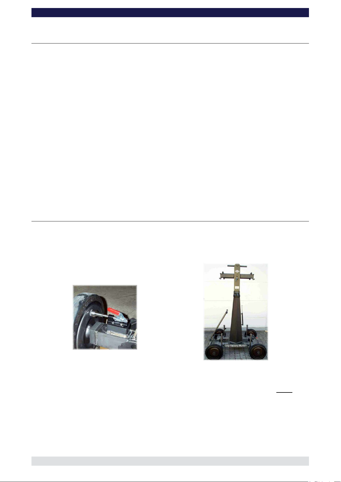
Locked wheel brake on Base Dolly
Base Dolly with mounting column and middle section
The GF-Multi Jib is a modular jib arm consisting of:
2 x 150cm sections plus respective rigging and parallelogram rods
1 x 100cm section plus respective rigging and parallelogram rods
1 x 50cm section plus respective rigging and parallelogram rods
1 x 30cm section plus respective rigging and parallelogram rods
1 x Rigging harness
2 x Rigging rod connectors
1 x Angle adjuster
1 x Counterweight bucket
1 x Remote bracket with angle adjuster
1 x Pivot section
1 x Pan bearing
1 x Mitchell adapter for pan bearing (or Euro-adapter for pan bearing)
In general the 2 x 150cm sections are to be used as front extensions whereas the 100, 50,
and 30cm sections can be used as rear or front sections.
Please refer to the technical drawings for all set-up configurations.
GF- Multi Jib assembly procedure on base dolly
Before and during assembly observe the Safety Guidelines.
1. Secure the base dolly so that it cannot move or roll. Lock all wheel brakes. Move the
steering rod towards the centre of the dolly or remove it so that the set-up personnel
do not trip over it.
2. Bolt the crane mounting column to the base dolly. Make sure that the 4 locking bolts
are locked securely. (Tip: the carrying handle on the bazooka should point away from
the steering end of dolly).
3. Located on the middle section are 2 tilt friction locks which may be used to lock the tilt
during set-up. Set the pivot arm at 90° to the centre post and lock these friction locks
which can be found on the left and right hand side of the middle section.
4. Mount the middle section on the mounting column. Lock the locking screw tightly.
Tip: A 12mm Allen key can be found in the mounting column’s handle to be used
as a lever
Page 5
GF-Multi Jib Instruction Manual
Page: 4
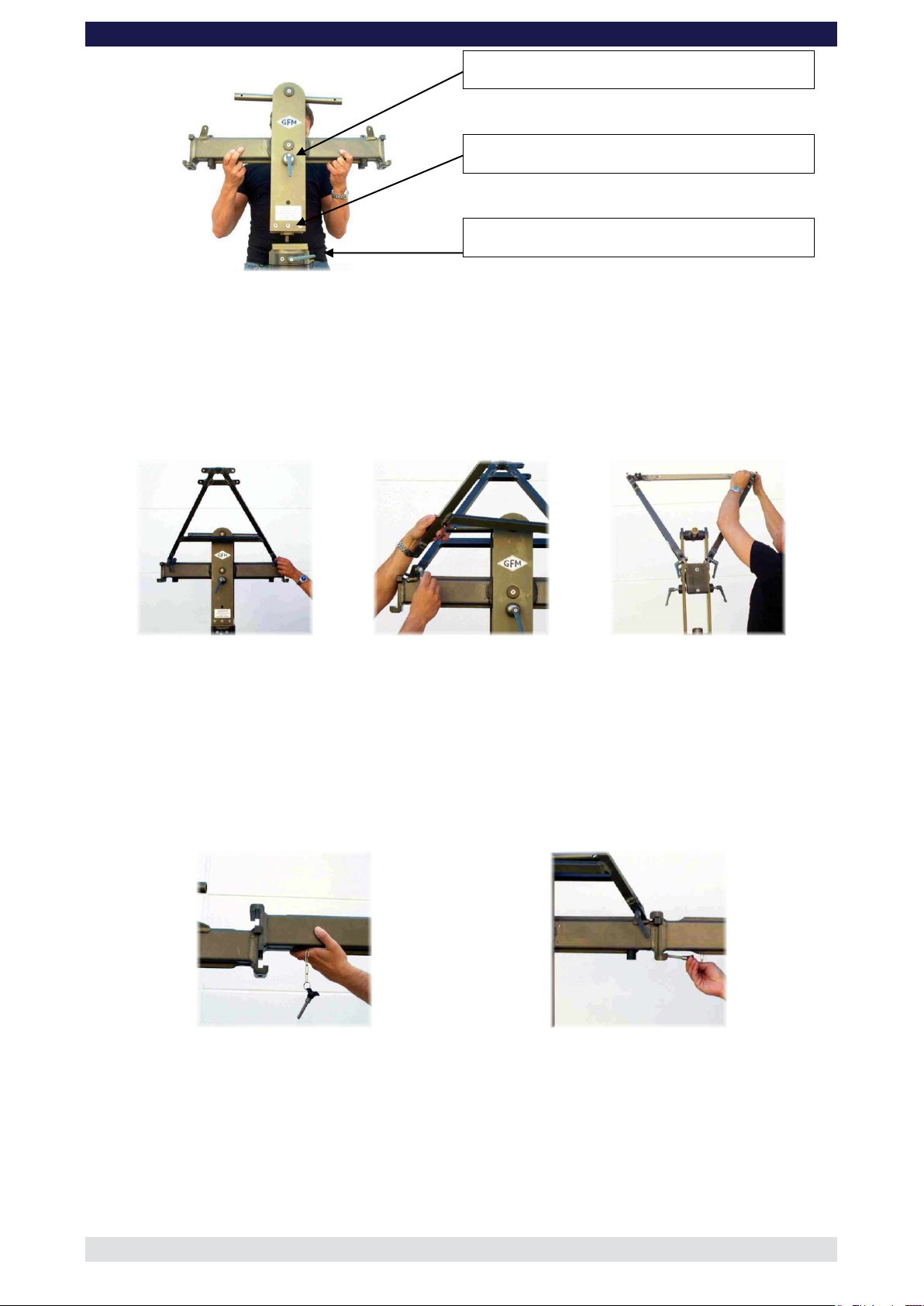
Tilt brake
Locking screw
Pan brake
Rigging harness assembly
Mounting an extension arm
Securing the arm with a safety pin
Attention : Pinch point – both tilt brakes should be locked during transport and
assembly!
5. Connect the 2 sections of the rigging harness to the middle section of the GF-9 and
lock securely with the 4 locking levers..
6. Connect the cross bar to stabilize the rigging harness. Ensure that the 2 locking pins
are inserted fully.
7. Depending on the version being assembled, connect the rear section to the middle
section. Slip the connection flanges into each other and secure with the provided
safety pin.
Tip: To avoid the sections jamming or getting stuck make sure that the sections
are joined parallel. Using a small amount of silicon spray also helps.
8. Connect the angle adjuster to the end of the respective section and secure it from the
inner side of the angle adjuster with the provided safety pin.
Page 6

GF-Multi Jib Instruction Manual
Page: 5
Mounting the angle adjuster
Securing it with a safety pin
Connecting the rigging rod to extension arm
Connecting the parallelogram rod
9. Connect the turnbuckles to the rigging harness. Depending on the rear length being
used, now connect the 2 rigging rods to the turnbuckles and in turn to the rigging rod
connections on the rear extension securing with the safety pins. Hand tighten the rods
by turning the turnbuckles until the rods are taut.
10. Connect the respective parallelogram rod to the middle section and the angle adjuster
and secure it with a safety pin at each end.
Tip: The angle adjuster has an integrated leveller. By turning it, the vertical plate
on the angle adjuster can be set to a perfect right angle. Correct setting of the angle
adjuster enhances the crane’s balance.
Page 7

GF-Multi Jib Instruction Manual
Page: 6
Securing the parallelogram rod
Levelling the angle adjuster
Connecting the rigging rods
Rigging rod connector
Connection for rigging rod
To assist the set-up procedure and to reduce the risk of accidents it is recommended to
use set-up support stands or rostrums to support the crane arm during set-up and
breakdown.
The rigging system
To enhance the rigidity and reduce the strain to the GF-Multi Jib arm, a rigging system
consisting of various rods and a V shaped harness is required. The rigging system must
be used for all versions.
The length of the rigging depends on the number of extensions to be used. As a rule, the
rigging runs from the rigging harness mounted on the pivot section to the last section at
the front or end of the crane. Detailed drawings can be found in the following pages.
General instructions for assembling the rigging:
1. After connecting the turnbuckles to the rigging harness, connect the required rigging
rod and secure the rods with the provided safety pin.
2. Depending on the version, attach the required number of rods and secure them with
the provided safety pins.
3. When the rods are connected together and secured with the respective safety pins,
connect the front rods to the connections for rigging rods on the respective section.
Attention: for certain versions it is necessary to use a rigging rod connector between
the rods.
Page 8

GF-Multi Jib Instruction Manual
Page: 7
Connecting the parallelogram support
Connecting the safety pin
Betrieb muß die
verstanden werden !
Betriebsanleitung
gelesen und
Vor Montage und
Grip Factory Munich
2996mm / 117,9"
3351mm / 131,9"
796mm / 31,3"
1276mm / 50,2"
1500mm / 59,1"
300mm / 11,8"
54kg /
119,1lbs
1000mm / 39,3"
252kg /
555,7lbs
678,5mm / 26,7"
783,5mm / 30,8"
Rigging Rods: 1450mm / 57,1" (bzw. 1400mm / 55,1") + 910mm / 35,8"
Betrieb muß die
verstanden werden !
Betriebsanleitung
gelesen und
Vor Montage und
Grip Factory Munich
Betrieb muß die
verstanden werden !
Betriebsanleitung
gelesen und
Vor Montage und
Grip Factory Munich
2996mm / 117,9"
3351mm / 131,9"
796mm / 31,3"
1276mm / 50,2"
3496mm / 137,6"
3851mm / 151,6"
1500mm / 59,1"
300mm / 11,8"
54kg /
119,1lbs
1000mm / 39,3"
252kg /
555,7lbs
43kg /
94,8lbs
1500mm / 59,1"1500mm / 59,1"
300mm / 11,8"
252kg /
555,7lbs
678,5mm / 26,7"
Rigging Rods: 1450mm / 57,1" + 1400mm / 55,1"
Rigging Rods: 1450mm / 57,1" (bzw. 1400mm / 55,1") + 910mm / 35,8"
When all the required rods are in place and connected, the turnbuckles on the rigging
harness can be hand turned until the rods are taut. The turnbuckles should adjust the
run of both sets of rods equally so that the arm is not bent or pulled to one side. Over
adjusting of the rods should be avoided.
Parallelogram supports:
1. For certain versions it is recommended to use the parallelogram supports. To see the
correct positioning, please refer to the drawing of the individual version. The supports
are bolted to both sides of the respective extension and connected to the
parallelogram with the locking pin from above as shown below.
Technical Specifications
GF-Multi Jib
Version 1-300
Version 2-300
Page 9

GF-Multi Jib Instruction Manual
Page: 8
Betrieb muß die
verstanden werden !
Betriebsanleitung
gelesen und
Vor Montage und
Grip Factory Munich
Betrieb muß die
verstanden werden !
Betriebsanleitung
gelesen und
Vor Montage und
Grip Factory Munich
Betrieb muß die
verstanden werden !
Betriebsanleitung
gelesen und
Vor Montage und
Grip Factory Munich
2996mm / 117,9"
3351mm / 131,9"
796mm / 31,3"
1276mm / 50,2"
3496mm / 137,6"
3851mm / 151,6"
4351mm / 171,3"
3996mm / 157,3"
1500mm / 59,1"
300mm / 11,8"
54kg /
119,1lbs
1000mm / 39,3"
252kg /
555,7lbs
1500mm / 59,1"1500mm / 59,1"
32kg /
70,6lbs
300mm / 11,8"
252kg /
555,7lbs
500mm / 19,7"
43kg /
94,8lbs
1500mm / 59,1"1500mm / 59,1"
300mm / 11,8"
252kg /
555,7lbs
678,5mm / 26,7"
Rigging Rods: 1450mm / 57,1" + 1400mm / 55,1" +
Rod Connector 100mm / 3,9" + 425mm / 16,7"
Rigging Rods: 1450mm / 57,1" + 1400mm / 55,1"
Rigging Rods: 1450mm / 57,1" (bzw. 1400mm / 55,1") + 910mm / 35,8"
Betrieb muß die
verstanden werden !
Betriebsanleitung
gelesen und
Vor Montage und
Grip Factory Munich
Betrieb muß die
verstanden werden !
Betriebsanleitung
gelesen und
Vor Montage und
Grip Factory Munich
Betrieb muß die
verstanden werden !
Betriebsanleitung
gelesen und
Vor Montage und
Grip Factory Munich
Betrieb muß die
verstanden werden !
Betriebsanleitung
gelesen und
Vor Montage und
Grip Factory Munich
2996mm / 117,9"
3351mm / 131,9"
796mm / 31,3"
1276mm / 50,2"
3496mm / 137,6"
3851mm / 151,6"
4351mm / 171,3"
3996mm / 157,3"
4851mm / 190,9"
4496mm / 177"
1500mm / 59,1"
300mm / 11,8"
54kg /
119,1lbs
1000mm / 39,3"
252kg /
555,7lbs
25kg /
55,1lbs
1000mm / 39,3"
1500mm / 59,1"1500mm / 59,1"
252kg /
555,7lbs
300mm / 11,8"
1500mm / 59,1"1500mm / 59,1"
32kg /
70,6lbs
300mm / 11,8"
252kg /
555,7lbs
500mm / 19,7"
43kg /
94,8lbs
1500mm / 59,1"1500mm / 59,1"
300mm / 11,8"
252kg /
555,7lbs
678,5mm / 26,7"
Rigging Rods: 1450mm / 57,1" + 1400mm / 55,1" +
Rod Connector 100mm / 3,9" + 910mm / 35,8"
Rigging Rods: 1450mm / 57,1" + 1400mm / 55,1" +
Rod Connector 100mm / 3,9" + 425mm / 16,7"
Rigging Rods: 1450mm / 57,1" + 1400mm / 55,1"
Rigging Rods: 1450mm / 57,1" (bzw. 1400mm / 55,1") + 910mm / 35,8"
Betrieb muß die
verstanden werden !
Betriebsanleitung
gelesen und
Vor Montage und
1476mm / 58,1"
996mm / 39,2"
2296mm / 90,4"
2651mm / 104,4"
60kg /
132,3lbs
1500mm / 59,1"
500mm / 19,7"
154kg /
339,6lbs
300mm / 11,8"
678,5mm / 26,7"
783,5mm / 30,8"
Rigging Rods: 1400mm / 55,1" + 280mm / 11,0"
Betrieb muß die
verstanden werden !
Betriebsanleitung
gelesen und
Vor Montage und
Betrieb muß die
verstanden werden !
Betriebsanleitung
gelesen und
Vor Montage und
1476mm / 58,1"
996mm / 39,2"
2296mm / 90,4"
2651mm / 104,4"
3496mm / 137,6"
3851mm / 151,6"
59kg /
130,1lbs
1500mm / 59,1"
1500mm / 59,1"
500mm / 19,7"
252kg /
555,7lbs
60kg /
132,3lbs
1500mm / 59,1"
500mm / 19,7"
154kg /
339,6lbs
300mm / 11,8"
678,5mm / 26,7"
Rigging Rods: 1400mm / 55,1" + 280mm / 11,0"
Rigging Rods: 1450mm / 57,1" + 1400mm / 55,1"
Version 3-300
Version 4-300
GF-Multi Jib
Version 1-500
Version 2-500
Page 10

GF-Multi Jib Instruction Manual
Page: 9
Betrieb muß die
verstanden werden !
Betriebsanleitung
gelesen und
Vor Montage und
Betrieb muß die
verstanden werden !
Betriebsanleitung
gelesen und
Vor Montage und
Betrieb muß die
verstanden werden !
Betriebsanleitung
gelesen und
Vor Montage und
1476mm / 58,1"
996mm / 39,2"
2296mm / 90,4"
2651mm / 104,4"
3496mm / 137,6"
3851mm / 151,6"
3796mm / 149,4"
4151mm / 163,4"
1500mm / 59,1"
300mm / 11,8"
1500mm / 59,1"
50kg /
110,3lbs
500mm / 19,7"
252kg /
555,7lbs
59kg /
130,1lbs
1500mm / 59,1"
1500mm / 59,1"
500mm / 19,7"
252kg /
555,7lbs
60kg /
132,3lbs
1500mm / 59,1"
500mm / 19,7"
154kg /
339,6lbs
300mm / 11,8"
678,5mm / 26,7"
Rigging Rods: 1400mm / 55,1" + 280mm / 11,0"
Rigging Rods: 1450mm / 57,1" + 1400mm / 55,1"
Rigging Rods: 1450mm / 57,1" + 1400mm / 55,1" + 280mm / 11,0"
Vor Montage und
gelesen und
Betriebsanleitung
verstanden werden !
Betrieb muß die
Betrieb muß die
verstanden werden !
Betriebsanleitung
gelesen und
Vor Montage und
Betrieb muß die
verstanden werden !
Betriebsanleitung
gelesen und
Vor Montage und
Betrieb muß die
verstanden werden !
Betriebsanleitung
gelesen und
Vor Montage und
1476mm / 58,1"
996mm / 39,2"
2296mm / 90,4"
2651mm / 104,4"
3496mm / 137,6"
3851mm / 151,6"
3796mm / 149,4"
4151mm / 163,4"
3996mm / 157,3"
4351mm / 171,3"
252kg /
555,7lbs
500mm / 19,7"
1500mm / 59,1"
1500mm / 59,1"
45kg /
99,2lbs
500mm / 19,7"
1500mm / 59,1"
300mm / 11,8"
1500mm / 59,1"
50kg /
110,3lbs
500mm / 19,7"
252kg /
555,7lbs
59kg /
130,1lbs
1500mm / 59,1"
1500mm / 59,1"
500mm / 19,7"
252kg /
555,7lbs
60kg /
132,3lbs
1500mm / 59,1"
500mm / 19,7"
154kg /
339,6lbs
300mm / 11,8"
678,5mm / 26,7"
Rigging Rods: 1400mm / 55,1" + 280mm / 11,0"
Rigging Rods: 1450mm / 57,1" + 1400mm / 55,1"
Rigging Rods: 1450mm / 57,1" + 1400mm / 55,1" + 280mm / 11,0"
Rigging Rods: 1450mm / 57,1" + 1400mm / 55,1" +
Rod Connector 100mm / 3,9" + 425mm / 16,7"
Vor Montage und
gelesen und
Betriebsanleitung
verstanden werden !
Betrieb muß die
Betrieb muß die
verstanden werden !
Betriebsanleitung
gelesen und
Vor Montage und
Betrieb muß die
verstanden werden !
Betriebsanleitung
gelesen und
Vor Montage und
Betrieb muß die
verstanden werden !
Betriebsanleitung
gelesen und
Vor Montage und
Betrieb muß die
verstanden werden !
Betriebsanleitung
gelesen und
Vor Montage und
1476mm / 58,1"
996mm / 39,2"
2296mm / 90,4"
2651mm / 104,4"
3496mm / 137,6"
3851mm / 151,6"
3796mm / 149,4"
4151mm / 163,4"
3996mm / 157,3"
4351mm / 171,3"
4496mm / 177"
4851mm / 190,9"
252kg /
555,7lbs
500mm / 19,7"
1500mm / 59,1" 1500mm / 59,1"
1000mm / 39,3"
37kg /
81,6lbs
252kg /
555,7lbs
500mm / 19,7"
1500mm / 59,1"
1500mm / 59,1"
45kg /
99,2lbs
500mm / 19,7"
1500mm / 59,1"
300mm / 11,8"
1500mm / 59,1"
50kg /
110,3lbs
500mm / 19,7"
252kg /
555,7lbs
59kg /
130,1lbs
1500mm / 59,1"
1500mm / 59,1"
500mm / 19,7"
252kg /
555,7lbs
60kg /
132,3lbs
1500mm / 59,1"
500mm / 19,7"
154kg /
339,6lbs
300mm / 11,8"
678,5mm / 26,7"
Rigging Rods: 1400mm / 55,1" + 280mm / 11,0"
Rigging Rods: 1450mm / 57,1" + 1400mm / 55,1"
Rigging Rods: 1450mm / 57,1" + 1400mm / 55,1" + 280mm / 11,0"
Rigging Rods: 1450mm / 57,1" + 1400mm / 55,1" +
Rod Connector 100mm / 3,9" + 425mm / 16,7"
Rigging Rods: 1450mm / 57,1" + 1400mm / 55,1" +
Rod Connector 100mm / 3,9" + 910mm / 35,8"
Version 3-500
Version 4-500
Version 5-500
Page 11

GF-Multi Jib Instruction Manual
Page: 10
GF 9 und Prüfbuch zuModel
Year of Construction
XXXX
check book
Betrieb muß die
verstanden werden !
Betriebsanleitung
gelesen und
Vor Montage und
XXX
beachten.
Only operate the crane
in accordance with
the instruction manual,
Serial Number
Baujahr
Serien-Nr.
safety notices and
Grip Factory Munich
Grip Factory Munich
Bedienungsanleitung
gemäß Beschilderung,
Krans sind die Angaben
Beim Betrieb des
SÜDDEUTSCHLAND
Typ
Manufacturer
Hersteller
1976mm / 77,8" 4151mm / 163,4"
3796mm / 149,4"1496mm / 58,9"
678,5mm / 26,7"
783,5mm / 30,8"
1000mm / 39,3"
1500mm / 59,1"
1500mm / 59,1"
300mm / 11,8"
60kg /
132,3lbs
186kg /
410,1lbs
Rigging Rods: 1450mm / 57,1" + 1400mm / 55,1" + 280mm / 11,0"
Betrieb muß die
verstanden werden !
Betriebsanleitung
gelesen und
Vor Montage und
Year of Construction
XXXX
check book
Grip Factory Munich
Grip Factory Munich
XXX
GF 9
beachten.
Only operate the crane
in accordance with
the instruction manual,
und Prüfbuch zu
Bedienungsanleitung
gemäß Beschilderung,
Krans sind die Angaben
Beim Betrieb des
SÜDDEUTSCHLAND
Typ
Model
Serial Number
Manufacturer
Baujahr
Serien-Nr.
Hersteller
safety notices and
GF 9 und Prüfbuch zuModel
Year of Construction
XXXX
check book
Betrieb muß die
verstanden werden !
Betriebsanleitung
gelesen und
Vor Montage und
XXX
beachten.
Only operate the crane
in accordance with
the instruction manual,
Serial Number
Baujahr
Serien-Nr.
safety notices and
Grip Factory Munich
Grip Factory Munich
Bedienungsanleitung
gemäß Beschilderung,
Krans sind die Angaben
Beim Betrieb des
SÜDDEUTSCHLAND
Typ
Manufacturer
Hersteller
1976mm / 77,8" 4151mm / 163,4"
3796mm / 149,4"1496mm / 58,9"
4351mm / 171,3"
3996mm / 157,3"
678,5mm / 26,7"
783,5mm / 30,8"
1000mm / 39,3"
1500mm / 59,1"
1500mm / 59,1"
300mm / 11,8"
60kg /
132,3lbs
196kg /
432,1lbs
186kg /
410,1lbs
1000mm / 39,3"
1500mm / 59,1"
1500mm / 59,1"
500mm / 19,7"
60kg /
132,3lbs
Rigging Rods: 1450mm / 57,1" + 1400mm / 55,1" +
Rod Connector 100mm / 3,9" + 425mm / 16,7"
Rigging Rods: 1450mm / 57,1" + 1400mm / 55,1" + 280mm / 11,0"
GF-Multi Jib
Version 1-1000
Version 2-1000
Balancing the crane arm
Attention: When loading the jib the maximum working load capacities / payloads
must never be exceeded.
As a rule, no more than 252kg / 554lbs of counterweight may be used in the
counterweight bucket or 260kg / 572lbs when using the counterweight rod.!
After the assembly procedure has been completed, the remote head and camera etc may
now be assembled. Place the correct amount of counterweight in the weight bucket to
balance the load.
Attention: we recommend that the camera and remote head are additionally secured
to the remote head mount with a safety chain or cable.
Place the required amount of counterweights in the weight bucket so that the jib arm
becomes balanced and remains in the horizontal position. If necessary, the jib can be fine
balanced by adjusting the sliding weight on the rear parallelogram at the weight bucket. Do
not forget to lock the sliding weight in position before tilting the arm.
The counterweight bucket door must be locked when operating the jib.
Page 12

GF-Multi Jib Instruction Manual
Page: 11
Deloading:
Attention: The counterweights must always be gradually removed from the
counterweight bucket before removing the camera or remote head. Extreme caution
must be given to the shifting payload at all times. When dismantling the jib it is
essential that the whole arm is supported fully by a stable underlay i.e. rostrum or
ground surface. In any case the remote bracket should not be in the air without
support.
Attention: all necessary precautions should be taken so that unauthorized third
parties cannot use the jib.
General Safety
Operational conditions:
At a wind speed of 35km/h 22mph crane operation must be stopped and the crane
secured, dismounted and the necessary safety precautions taken.
If, for example, it takes 2 mins. to unload the counterweights and take the necessary
precautions to secure the crane, one must commence with the procedure at a wind speed
of 30km/h / 19mph. DIN15019, part 1, section 6.13.
The crane may not be used in a lightning storm as there is the danger of electrocution.
Notice:
When operating the crane with the push bar mounted on the dolly, pay attention that the
crane arm at no time collides with the push bar.
 Loading...