

Page 1

Grip Factory Munich
YOUR INNOVATIVE PARTNER FOR CAMERA SUPPORT
GF-9
Crane System
Instruction Manual
Valid: Sep. 2007
Grip Factory Munich GmbH
Fürholzener Straße 1
85386 Eching bei München
Germany
Tel.: +49 (0) 89 319 0 129-0
Fax: +49 (0) 89 319 0 129-9
e-Mail: info@g-f-m.net
http://www.g-f-m.net
Page 2

GF-9 Crane System Instruction Manual
Page: 1
Contents:
SAFETY GUIDELINES ............................................................................................... 2
GF- 9 Assembly procedure on base dolly ................................................................... 3
GF- 9 assembly on tripod ............................................................................................ 6
Assembly of GF- 9 Crane System on Tripod and Track Dolly ..................................... 8
The rigging system ..................................................................................................... 9
Assembly and Technical Specifications .................................................................... 11
Version 1-150 D .......................................................................................................... 11
Version 2-150 D .......................................................................................................... 12
Version 3-150 D .......................................................................................................... 13
Version 4-150 D .......................................................................................................... 14
Version 5-150 D .......................................................................................................... 16
Version 6-150 D .......................................................................................................... 18
Version 7-150 D .......................................................................................................... 20
Version 8-150 D .......................................................................................................... 22
Version 9-150 D .......................................................................................................... 24
Version 10-150 D ........................................................................................................ 26
Balancing the crane arm ........................................................................................... 28
Deloading: .................................................................................................................. 28
General Safety .......................................................................................................... 28
Accessories for GF- 9 crane ..................................................................................... 29
GF-9 Base as Track- or Westerndolly ....................................................................... 30
Page 3

GF-9 Crane System Instruction Manual
Page: 2
SAFETY GUIDELINES
The assembly instructions must be read and understood before set-up or operation. The crane may only be
assembled in accordance with the manufacturer’s instruction manual. The manufacturers technical
specifications and limits must be adhered to at all times and in no way exceeded.
The GF-9 Crane may only be set-up or operated by trained and experienced personnel. To avoid misuse by
untrained personnel, the crane should be dismantled when not in use or under supervision.
For further information on the qualifications required for test personnel please refer to BGV 1, § 33 and §34.
The crane may not be assembled or operated under the influence of alcohol, drugs or any other intoxicating
substances. The respective protective clothing e.g. gloves, should be worn.
The manufacturer accepts no liability for damages or injuries for incidents or accidents occurring due to
negligence by the crane operator or misuse of the crane or disregarding the instruction manual..
Before assembling the crane ensure that the ground surface is stable and cannot give way. The ground
surface must be stable enough to support at least 500 kg/m2 = 1100 lbs/ sq yard.
Crane operation is only allowed with solid tires. Use with pneumatic wheels is not allowed.
The crane dolly must be level at all times. If necessary, level the crane base dolly with the provided levelling
legs or level it on the tripod base. Whether operating or moving the crane on track or on a solid ground
surface it is essential that the track or surface is completely level, stable and free from obstructions.
When operating the crane on track, ensure that the track is level, properly laid and constructed. The correct
underlay must be used to ensure that the track and underlay are secured against moving, slipping and
collapse. Ensure that the underlay meets the specified support and stability requirements.
Extreme caution must be used if tracking on curved track (no faster than a slow walking pace).
Use of the crane on insert vehicles, camera cars or any motorised vehicle is not allowed. The manufacturer
accepts no liability for damages or injuries for incidents or accidents occurring due to use of the crane on
insert vehicles, camera cars or any other motorised vehicles.
Changing weather conditions should be taken into consideration. The crane must be taken out of operation
before the operational wind speed reaches 35kmh. / 22mph. See page 24.
The complete lift and panning range of the crane must be kept clear of obstructions at all times. A safety
clearance of 0.5m / 19" to surrounding objects and 1m /39” to persons must be observed on all sides of the
crane during operation.
The crane may not be used in the direct vicinity of high voltage power cables. To avoid accidents due to
misuse in the vicinity of high voltage power cables, Safety Guidelines (especially VBG 1 and 4) as well as
VDE regulations (especially 0105 part 100) must be adhered to. If the nominal voltage cannot be
determined, a minimum clearance of 5m / 16ft must be kept at all times. Failing to do so can cause fatalities.
No loose objects may be stored or placed on the crane.
Before the counterweights are removed from the bucket, ensure that the remote bracket is resting on the
ground or alternatively supported by an appropriate stable underlay. Gradually remove the counterweights
before the remote head or camera are removed.
In the interest of safe crane operation abrupt, sudden, abrupt movement of the crane should be avoided.
Only original accessories manufactured by GFM may be used with the crane.
Page 4
GF-9 Crane System Instruction Manual
Page: 3
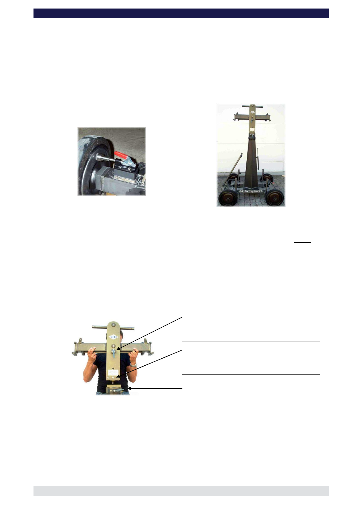
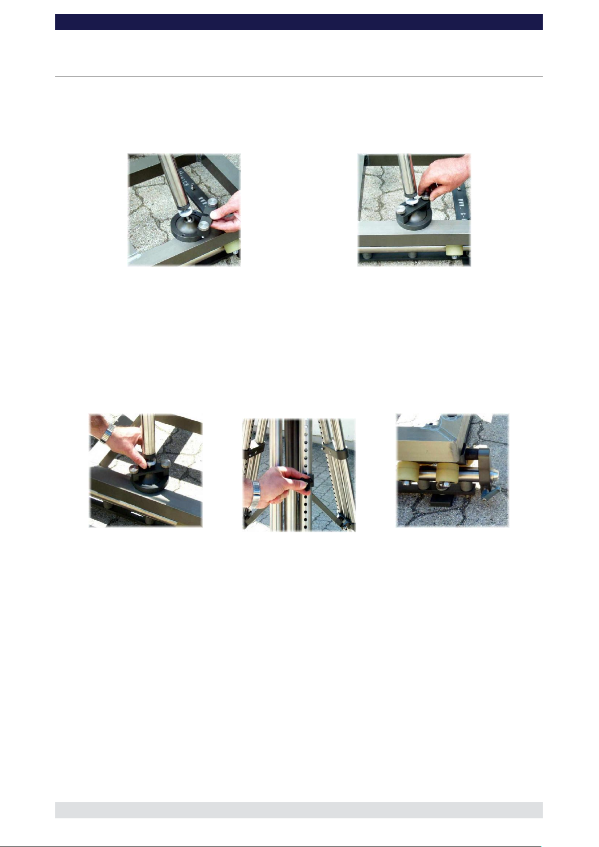
Locked wheel brake on Base Dolly
Base Dolly with mounting column and middle section
Tilt brake
Locking screw
Pan brake
GF- 9 Assembly procedure on base dolly
Before and during assembly observe the Safety Guidelines.
For all versions::
1. Secure the base dolly so that it cannot move or roll. Lock all wheel brakes. Move the
steering rod towards the centre of the dolly or remove it so that the set-up personnel
do not trip over it.
2. Bolt the crane mounting column to the base dolly. Make sure that the 4 locking bolts
are locked securely. (Tip: the carrying handle on the bazooka should point away from
the steering end of dolly).
3. Located on the middle section are 2 tilt friction locks which may be used to lock the tilt
during set-up. Set the pivot arm at 90° to the centre post and lock these friction locks
which can be found on the left and right hand side of the middle section.
4. Mount the middle section on the mounting column. Lock the locking screw tightly.
Tip: A 12mm Allen key can be found in the mounting column’s handle to be used
as a lever
Attention : Pinch point – both tilt brakes should be locked during transport and
assembly!
Page 5
GF-9 Crane System Instruction Manual
Page: 4
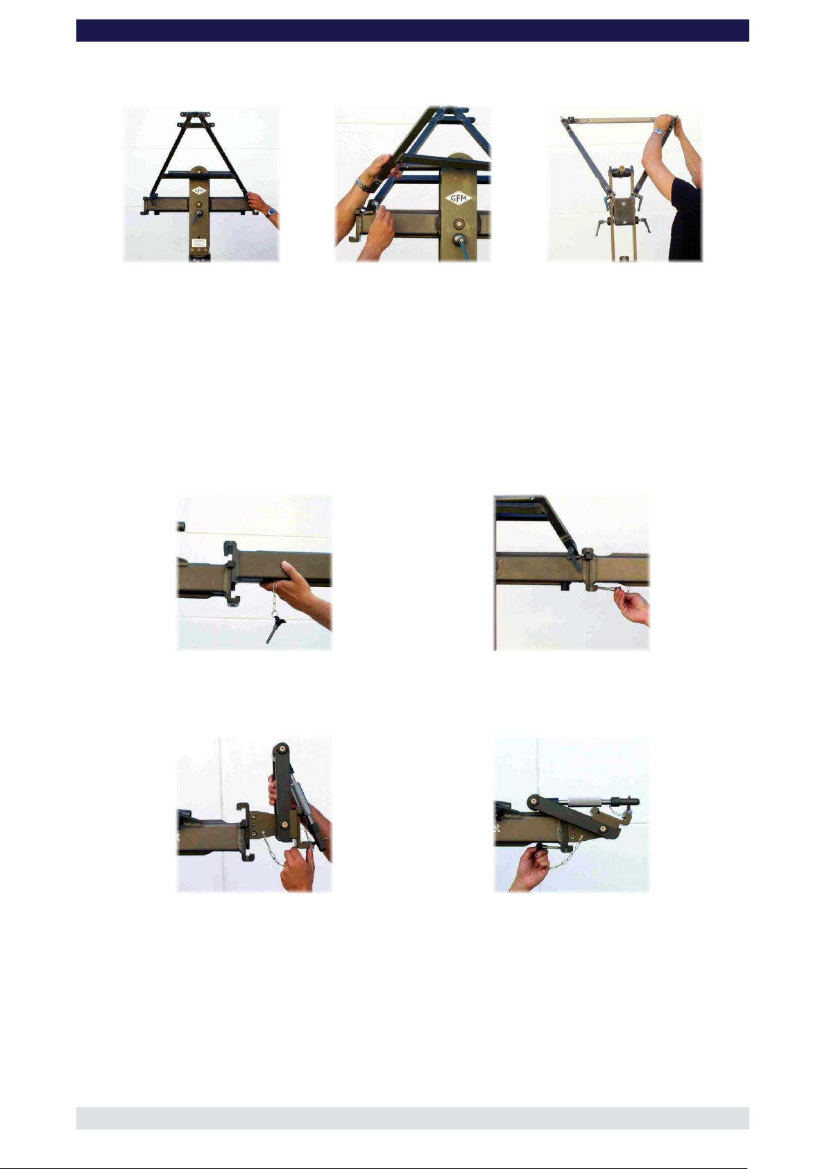
Rigging harness assembly
Mounting an extension arm
Securing the arm with a safety pin
Mounting the angle adjuster
Securing it with a safety pin
5. Connect the 2 sections of the rigging harness to the middle section of the GF-9 and
lock securely with the 4 locking levers..
6. Connect the cross bar to stabilize the rigging harness. Ensure that the 2 locking pins
are inserted fully.
7. Depending on the version being assembled, connect the 100cm section or the 150cm
section (this particular section has 4 connections for rigging rods) to the middle
section. Slip the connection flanges into each other and secure with the provided
safety pin.
Tip: To avoid the sections jamming or getting stuck make sure that the sections
are joined parallel. Using a small amount of lubricant also helps. We suggest rubbing
the joints with an oiled.
8. Connect the angle adjuster to the end of the 100cm or 150cm section and secure it
from the inner side of the angle adjuster with the provided safety pin.
9. Connect the turnbuckles to the rigging harness. Depending on the rear length being
used, now connect the 4 rigging rods to the turnbuckles and in turn to the rigging rod
connections on the rear extension securing with the safety pins. Hand tighten the rods
by turning the turnbuckles until the rods are taut, then secure the turnbuckles with the
locking nuts.
Page 6
GF-9 Crane System Instruction Manual
Page: 5
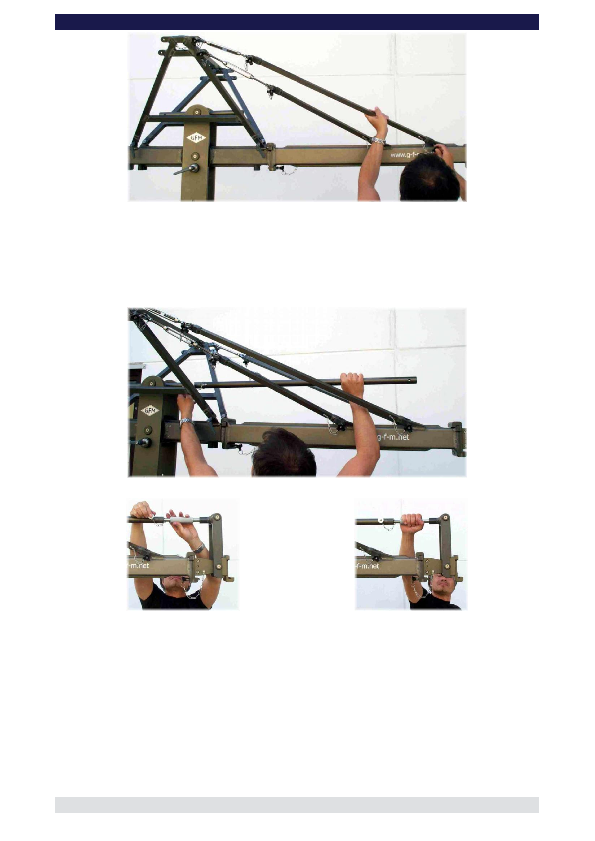
Connecting the rigging rod to extension arm
Connecting the parallelogram rod
Securing the parallelogram rod
Levelling the angle adjuster
10. Connect the parallelogram rod (either 100cm or 150cm) to the middle section and the
angle adjuster and secure it with a safety pin at each end.
Tip: The angle adjuster has an integrated leveller. By turning it, the vertical plate
on the angle adjuster can be set to a perfect right angle. Correct setting of the angle
adjuster enhances the crane’s balance.
The assembly procedure up to this point is the same in all versions.
To assist the set-up procedure and to reduce the risk of accidents it is recommended to
use set-up support stands or rostrums to support the crane arm during set-up and
breakdown.
Page 7
GF-9 Crane System Instruction Manual
Page: 6
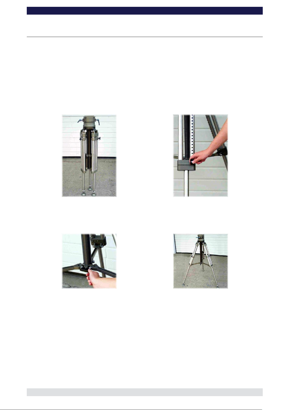
Folded tripod
Securing the tripod legs
Locking the spreader
Extended tripod, maximum width
GF- 9 assembly on tripod
Alternatively the GF-9 may also be mounted on the dedicated GFM Heavy Duty Tripod.
Should the pan bearing not already be on the tripod at this stage it must be mounted and
securely bolted into place by securing the 6 locking bolts with an Allen Key.
Before assembling the crane on the tripod ensure that the ground surface is stable and
cannot give way and that the tripod legs cannot sink into the ground. The surface must be
able to support at least 500 kg/m2 = 1100 lbs/ sq yard. Please follow the following steps:
1. For crane operation the tripod legs must be extended to the maximum length and in
turn each leg must be secured with it’s locking pin.
2. When all 3 legs are extended, spread the tripod spreader so that the legs are at their
maximum width. Secure the spreader by locking it off with the wing nut. Always
ensure that the tripod legs are spread as wide as possible.
Page 8

GF-9 Crane System Instruction Manual
Page: 7
Levelling the tripod
Securing the leveller
Maximum tilt on tripod
Avoid forceful stops into the pan bearing
Max. 30 mm
1 inch
3. Further levelling of the tripod can be achieved by turning the leveller at the bottom of
each leg and observing the water level on the pan section. Attention: the maximum
levelling range is 30mm / 1inch (see below picture). When level, lock off the leveller to
avoid any unwanted movement and twisting.
4. Now the tripod is ready. Continue assembly as from § 3 page 3.
Attention:
When using the crane ensure that the tripod legs/feet cannot shift or move, for example
when panning the arm.
When the crane is at it’s maximum tilt angle, be it in the plus or minus range, it is
important, especially when using the 100cm / 3ft rear section, to stop the arm crashing into
the pan bearing with force. A hard collision can cause the crane to topple over.!
Page 9
GF-9 Crane System Instruction Manual
Page: 8
Securing the Tripod on the Track Dolly
Levelling and securing the legs
Adjusting and securing the tripod leg
Braking the Track Dolly
Assembly of GF- 9 Crane System on Tripod and Track Dolly
The assembly of the GF-9 on the Track Dolly is continued in much the same manner as
already described but a few details must be observed:
1. Upon placing the 3 Tripod legs in the fittings on the Track Dolly secure each one with
the 3 locking fasteners securing each with the 2 locking screws until hand tight.
2. Level the Tripod on the Track Dolly by turning the leveller at the bottom of each leg
and observing the water level on the pan section. Attention: the maximum levelling
range is 30mm / 1inch (see page 7). When level, lock off the leveller to avoid any
unwanted movement and twisting. Furthermore it is essential and a prerequisite that
the track is level and supported correctly. Ensure that the track properly laid and
constructed. The correct underlay must be used to ensure that the track and underlay
are secured against moving, slipping and collapse. Ensure that the underlay meets
the specified support and stability requirements.
3. The maximum Pivot Point Height ( tilt point ) allowed when using the GF-9 on the
Tripod mounted on the Track Dolly is 172cm / 5’ 7“ based on the distance from the
actual ground to the Pivot Point. This height may not be exceeded. When using GFM
Track the Tripod can be extended to the 15th hole and then secured with the
respective safety pins.
4. During assembly it is very important to secure the Track Dolly so it cannot move on
the track. For this purpose GFM Dolly Stoppers, sand bags or similar should be used.
Continue the assembly from § 3 page 3.
Page 10
GF-9 Crane System Instruction Manual
Page: 9
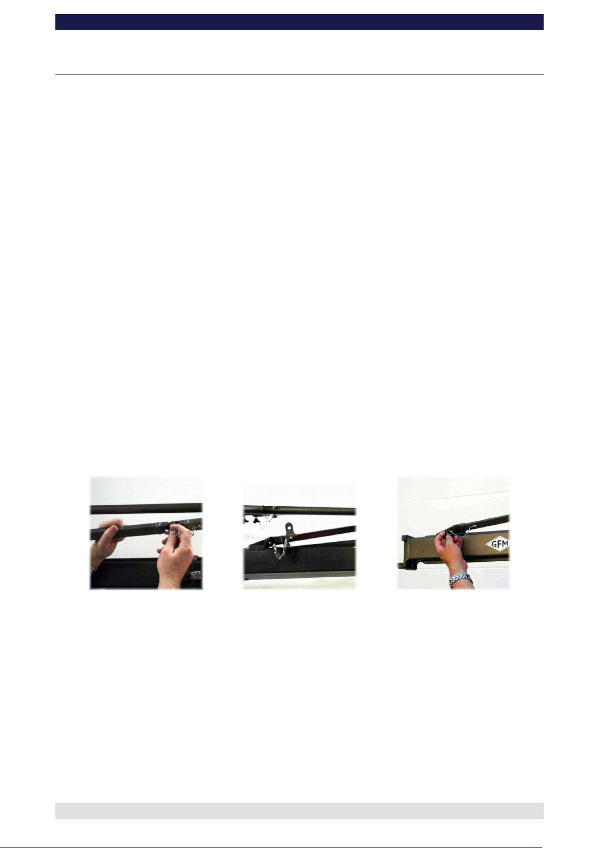
Connecting the rigging rods
Rigging rod with double connectors
Connection for rigging rod
The rigging system
To enhance the rigidity and reduce the strain to the GF-9 arm, a rigging system consisting
of various rods and a V shaped harness is required. The rigging system must be used for
all versions.
To simplify assembly, all rigging rods, with the exception of the ones required for the
100cm and 50cm sections, are identical.
The length of the rigging depends on the number of extensions to be used. As a rule, the
rigging runs from the rigging harness mounted on the pivot section to the last section
(Versions 1 to 5) at the front or end of the crane. From Version 6 onwards the rigging runs
from the rigging harness mounted on the pivot section to the last section 150cm / 5ft
section at the front or end of the crane. Detailed drawings can be found in the following
pages. A double rigging system is required as of version 9. In this case the lower rigging
rods connect from the rigging harness to the second section whereby the 2 rods with the
double connectors should be connected to the second extension.
General instructions for assembling the rigging:
1. After connecting the turnbuckles to the rigging harness, connect the required rigging
rod and secure the rods with the provided safety pin.
2. Depending on the version, attach the required number of rods and secure them with
the provided safety pins.
3. Version 9 onwards requires a double rigging system (upper/long and lower/short).
The lower rods connect to the second extension. The 2 rods with the double
connectors as shown below must be connected to the second section with the vertical
connector in an upward direction ( accepts the adjustable rigging rod support).
Versions 1 to 8 have a single rigging system.
4. When the rods are connected together and secured with the respective safety pins,
connect the front rods to the connections for rigging rods on the respective section.
Attention: for certain versions it is necessary to use a rigging rod connector between
the second and third rigging rod (as seen from the pivot section) in the upper (long)
rigging.
5. When all the required rods are in place and connected, the turnbuckles on the rigging
harness can be hand turned until the rods are taut . The turnbuckles should adjust the
run of both sets of rods equally so that the arm is not bent or pulled to one side. Over
adjusting of the rods should be avoided.
Page 11

GF-9 Crane System Instruction Manual
Page: 10
Rigging rod connector
Adjusting the turnbuckle!
Adjustable rigging rod support
Connecting the parallelogram support
Setting the adjustable rigging rod
support
Connecting the safety pin
6. Now connect the adjustable rigging rod support between the vertical connection on
the second lower rigging rod and the rigging rod connector between the second and
third upper rigging rod, securing with the attached safety pins. Now the adjustable
rigging rod support can also be adjusted to ensure that the rods are straight. The
adjustable rigging rod support provides extra support to the rigging and is used in
versions 9 & 10.
Parallelogram supports:
1. From version 3 onwards it is recommended to use the parallelogram supports. To see
the correct positioning, please refer to the drawing of the individual version. The
supports are bolted to both sides of the respective extension and connected to the
parallelogram with the locking pin from above as shown below.
Page 12

GF-9 Crane System Instruction Manual
Page: 11
Front extension arms required
1 x 150 cm / 5’
Rear extension arm required
1 x 150 cm / 5’
Lift range
358 cm / 11’ 8”
Maximum remote bracket height
376 cm / 12’ 7“
Lift capacity
45 kg / 100 lbs
Counterweight required for max. load
28 kg / 61 lbs
Counterweight required to balance empty arm
0 kg / 0 lbs
Dolly weight
112 kg / 246 lbs
Crane weight (excluding dolly and weights)
92 kg / 202 lbs
Arm reach (pivot to camera head mount)
235 cm / 7’ 8“
Length of rear end (pivot to outside of bucket)
247 cm / 8’ 1“
Assembly and Technical Specifications
Version 1-150 D
Continue from § 10, page 5
11. Connect one of the 150cm / 5’ sections to the middle section. Slip the connection
flanges into each other and secure them with the provided safety pin.
12. Connect 2 rigging rods to the turnbuckles and secure with the safety pins. Then
connect the rods to the rigging rod connectors on the 150cm / 5’ section and secure
with the safety pins.
13. Adjust the turnbuckles until the rod are taut.
14. Connect one of the 150cm / 5’ parallelogram rods to the middle section and secure it
with a safety pin.
15. Connect the remote bracket angle adjuster to the end of the 150cm / 5’ section and
secure it with the provided safety pin.
Tip: The angle adjuster has an integrated leveller. By turning it, the vertical plate
on the angle adjuster can be set to a perfect right angle. Correct setting of the angle
adjuster enhances the crane’s balance.
16. Insert the rod on the remote bracket angle adjuster into the parallelogram rod a
secure with the safety pin.
17. As required, attach the weight bucket or weight rod to the opposite end of the crane
by inserting the male flange into the female flange on the angle adjuster. Secure it
with the safety pin.
Tip: The angle adjuster has an integrated leveller. By turning it, the vertical plate
on the angle adjuster can be set to a perfect right angle. Correct setting of the angle
adjuster enhances the crane’s balance. Level the weight bucket before loading any
weights
Before operation, all locking pins, locking screws etc should be inspected to ensure
that all assembly sections are securely fastened.
Page 13

GF-9 Crane System Instruction Manual
Page: 12
Front extension arms required
1 x 150 cm / 5’ + 100 cm / 3’ 3”
Rear extension arm required
1 x 150 cm / 5’
Lift range
538 cm / 17’ 7”
Maximum remote bracket height
466 cm / 15’ 3“
Lift capacity
45 kg / 99 lbs
Counterweight required for max. load
64 kg / 140 lbs
Counterweight required to balance empty arm
0 kg / 0 lbs
Dolly weight
112 kg / 246 lbs
Crane weight (excluding dolly and weights)
98 kg / 215 lbs
Arm reach (pivot to camera head mount)
335 cm / 10’ 11“
Length of rear end (pivot to outside of bucket)
247 cm / 8’ 1“
Version 2-150 D
Continue from § 10, page 5
11. Connect one of the 150cm / 5’ sections to the middle section. Slip the connection
flanges into each other and secure them with the provided safety pin.
12. Connect the 100cm / 3’3” sections to the 150cm / 5’. Slip the connection flanges into
each other and secure them with the provided safety pin.
13. Connect 2 rigging rods to the turnbuckles and secure with the safety pins.
14. Connect 2, 100cm / 3’3” rigging rods and in turn connect these rods to the rigging rod
connectors on the 100cm / 3’3” section and secure with the safety pins.
15. Adjust the turnbuckles until the rod are taut.
16. Connect one of the 150cm / 5’ parallelogram rods to the middle section and secure it
with a safety pin.
17. Connect the 100cm / 3’3” parallelogram rod to the 150cm / 5’ parallelogram rod and
secure it with a safety pin.
18. Connect the remote bracket angle adjuster to the end of the 150cm / 5’ section and
secure it with the provided safety pin.
Tip: The angle adjuster has an integrated leveller. By turning it, the vertical plate
on the angle adjuster can be set to a perfect right angle. Correct setting of the angle
adjuster enhances the crane’s balance.
19. Insert the rod on the remote bracket angle adjuster into the parallelogram rod a
secure with the safety pin.
20. As required, attach the weight bucket or weight rod to the opposite end of the crane
by inserting the male flange into the female flange on the angle adjuster. Secure it
with the safety pin.
Tip: The angle adjuster has an integrated leveller. By turning it, the vertical plate
on the angle adjuster can be set to a perfect right angle. Correct setting of the angle
adjuster enhances the crane’s balance. Level the weight bucket before loading any
weights
Before operation, all locking pins, locking screws etc should be inspected to ensure
that all assembly sections are securely fastened.
Page 14

GF-9 Crane System Instruction Manual
Page: 13
Front extension arms required
2 x 150 cm / 5’
Rear extension arm required
1 x 150 cm / 5’
Lift range
628 cm / 20’ 7”
Maximum remote bracket height
511 cm / 16’ 9“
Lift capacity
45 kg / 99 lbs
Counterweight required for max. load
84 kg / 184 lbs
Counterweight required to balance empty arm
8 kg / 17 lbs
Dolly weight
112 kg / 246 lbs
Crane weight (excluding dolly and weights)
101 kg / 222 lbs
Arm reach (pivot to camera head mount)
385 cm / 12’ 7“
Length of rear end (pivot to outside of bucket)
247 cm / 8’ 1“
Version 3-150 D
Continue from § 10, page 5
11. Connect one of the 150cm / 5’ sections to the middle section. Slip the connection
flanges into each other and secure them with the provided safety pin.
12. Connect the 100cm / 3’3” sections to the 150cm / 5’. Slip the connection flanges into
each other and secure them with the provided safety pin.
13. Connect 2 rigging rods to the turnbuckles and secure with the safety pins.
14. Connect another 2 rigging rods to the first 2 and in turn connect these rods to the
rigging rod connectors on the last section and secure with the safety pins.
15. Adjust the turnbuckles until the rod are taut.
16. Connect one of the 150cm / 5’ parallelogram rods to the middle section and secure it
with a safety pin.
17. Connect the another 150cm / 5’ parallelogram rod to the first parallelogram rod and
secure it with a safety pin.
18. Connect the remote bracket angle adjuster to the end of the last section and secure it
with the provided safety pin.
Tip: The angle adjuster has an integrated leveller. By turning it, the vertical plate
on the angle adjuster can be set to a perfect right angle. Correct setting of the angle
adjuster enhances the crane’s balance.
19. Insert the rod on the remote bracket angle adjuster into the parallelogram rod a
secure with the safety pin.
20. As required, attach the weight bucket or weight rod to the opposite end of the crane
by inserting the male flange into the female flange on the angle adjuster. Secure it
with the safety pin.
Tip: The angle adjuster has an integrated leveller. By turning it, the vertical plate
on the angle adjuster can be set to a perfect right angle. Correct setting of the angle
adjuster enhances the crane’s balance. Level the weight bucket before loading any
weights
Before operation, all locking pins, locking screws etc should be inspected to ensure
that all assembly sections are securely fastened.
Page 15

GF-9 Crane System Instruction Manual
Page: 14
Front extension arms required
2 x 150 cm / 5’ + 100cm / 3’ 3”
Rear extension arm required
1 x 150 cm / 5’
Lift range
808 cm / 26’ 6”
Maximum remote bracket height
601 cm / 19’ 8“
Lift capacity
45 kg / 99 lbs
Counterweight required for max. load
126 kg / 277 lbs
Counterweight required to balance empty arm
22 kg / 48 lbs
Dolly weight
112 kg / 246 lbs
Crane weight (excluding dolly and weights)
108 kg / 237 lbs
Arm reach (pivot to camera head mount)
485 cm / 15’ 10“
Length of rear end (pivot to outside of bucket)
247 cm / 8’ 1“
Version 4-150 D
Continue from § 10, page 5
11. Connect one of the 150cm / 5’ sections to the middle section. Slip the connection
flanges into each other and secure them with the provided safety pin.
12. Connect another of the 150cm / 5’ sections to the first section. Slip the connection
flanges into each other and secure them with the provided safety pin.
13. Connect the 100cm / 3’3” section to the last section. Slip the connection flanges into
each other and secure them with the provided safety pin.
14. Connect 2 rigging rods to the turnbuckles and secure with the safety pins.
15. Connect another 2 rigging rods to the first 2 and secure with the safety pins.
16. Connect 2, 100cm / 3’3” rigging rods to these and in turn connect the rods to the
rigging rod connectors on the 100cm / 3’3” section and secure with the safety pins.
17. Adjust the turnbuckles until the rods are taut.
18. Connect one of the 150cm / 5’ parallelogram rods to the middle section and secure it
with a safety pin.
19. Connect another 150cm / 5’ parallelogram rod to the first parallelogram rod and
secure it with a safety pin.
20. Connect the 100cm / 3’3” parallelogram rod to the last parallelogram rod and secure it
with a safety pin.
21. Mount the parallelogram rod support to the second section and second rod as
described on page 10.
22. Connect the remote bracket angle adjuster to the end of the last section and secure it
with the provided safety pin.
Tip: The angle adjuster has an integrated leveller. By turning it, the vertical plate
on the angle adjuster can be set to a perfect right angle. Correct setting of the angle
adjuster enhances the crane’s balance.
23. Insert the rod on the remote bracket angle adjuster into the parallelogram rod a
secure with the safety pin.
Page 16

GF-9 Crane System Instruction Manual
Page: 15
24. As required, attach the weight bucket or weight rod to the opposite end of the crane
by inserting the male flange into the female flange on the angle adjuster. Secure it
with the safety pin.
Tip: The angle adjuster has an integrated leveller. By turning it, the vertical plate
on the angle adjuster can be set to a perfect right angle. Correct setting of the angle
adjuster enhances the crane’s balance. Level the weight bucket before loading any
weights
Before operation, all locking pins, locking screws etc should be inspected to ensure
that all assembly sections are securely fastened.
Page 17

GF-9 Crane System Instruction Manual
Page: 16
Front extension arms required
3 x 150 cm / 5’
Rear extension arm required
1 x 150 cm / 5’
Lift range
898 cm / 29’ 5”
Maximum remote bracket height
646 cm / 21’ 2“
Lift capacity
30 kg / 66 lbs
Counterweight required for max. load
106 kg / 233 lbs
Counterweight required to balance empty arm
36 kg / 79 lbs
Dolly weight
112 kg / 246 lbs
Crane weight (excluding dolly and weights)
112 kg / 246 lbs
Arm reach (pivot to camera head mount)
535 cm / 17’ 6“
Length of rear end (pivot to outside of bucket)
247 cm / 8’ 1“
Version 5-150 D
Continue from § 10, page 5
11. Connect one of the 150cm / 5’ sections to the middle section. Slip the connection
flanges into each other and secure them with the provided safety pin.
12. Connect another the 2 of the 150cm / 5’ sections to the first section. Slip the
connection flanges into each other and secure them with the provided safety pin.
13. Connect 2 rigging rods to the turnbuckles and secure with the safety pins.
14. Connect another 2 rigging rods to the first 2 and secure with the safety pins.
15. Connect another 2 rigging rods to the second 2 and secure with the safety pins and in
turn connect the rods to the rigging rod connectors on the last section and secure with
the safety pins.
16. Adjust the turnbuckles until the rods are taut.
17. Connect one of the 150cm / 5’ parallelogram rods to the middle section and secure it
with a safety pin.
18. Connect another 2, 150cm / 5’ parallelogram rod to the first parallelogram rod and
secure it with a safety pin.
19. Mount the parallelogram rod support to the second section and second rod as
described on page 10.
20. Connect the remote bracket angle adjuster to the end of the last section and secure it
with the provided safety pin.
Tip: The angle adjuster has an integrated leveller. By turning it, the vertical plate
on the angle adjuster can be set to a perfect right angle. Correct setting of the angle
adjuster enhances the crane’s balance.
21. Insert the rod on the remote bracket angle adjuster into the parallelogram rod a
secure with the safety pin.
22. As required, attach the weight bucket or weight rod to the opposite end of the crane
by inserting the male flange into the female flange on the angle adjuster. Secure it
with the safety pin.
Tip: The angle adjuster has an integrated leveller. By turning it, the vertical plate
on the angle adjuster can be set to a perfect right angle. Correct setting of the angle
adjuster enhances the crane’s balance. Level the weight bucket before loading any
weights
Page 18

GF-9 Crane System Instruction Manual
Page: 17
Before operation, all locking pins, locking screws etc should be inspected to ensure
that all assembly sections are securely fastened.
Page 19

GF-9 Crane System Instruction Manual
Page: 18
Front extension arms required
3 x 150 cm / 5’ + 100 cm / 3’ 3”
Rear extension arm required
1 x 150 cm / 5’
Lift range
1077 cm / 35’ 4”
Maximum remote bracket height
735 cm / 24’ 1“
Lift capacity
30 kg / 110 lbs
Counterweight required for max. load
140 kg / 308 lbs
Counterweight required to balance empty arm
50 kg / 110 lbs
Dolly weight
112 kg / 246 lbs
Crane weight (excluding dolly and weights)
118 kg / 259 lbs
Arm reach (pivot to camera head mount)
635 cm / 20’ 10“
Length of rear end (pivot to outside of bucket)
247 cm / 8’ 1“
Version 6-150 D
Continue from § 10, page 5
11. Connect one of the 150cm / 5’ sections to the middle section. Slip the connection
flanges into each other and secure them with the provided safety pin.
12. Connect another 2 of the 150cm / 5’ sections to the first section. Slip the connection
flanges into each other and secure them with the provided safety pin.
13. Connect the 100cm / 3’3” section to the last section. Slip the connection flanges into
each other and secure them with the provided safety pin.
14. Connect 2 rigging rods to the turnbuckles and secure with the safety pins.
15. Connect another 2 rigging rods to each the first 2 and secure with the safety pins. In
turn connect the rods to the rigging rod connectors on the last 150cm /5ft section and
secure with the safety pins.
16. Adjust the turnbuckles until the rods are taut.
17. Connect one of the 150cm / 5’ parallelogram rods to the middle section and secure it
with a safety pin.
18. Connect another 2, 150cm / 5’ parallelogram rod to the first parallelogram rod and
secure them with safety pins.
19. Connect the 100cm / 3’3” parallelogram rod to the last parallelogram rod and secure it
with a safety pin.
20. Mount the parallelogram rod support to the second section and second rod as
described on page 10.
21. Connect the remote bracket angle adjuster to the end of the last section and secure it
with the provided safety pin.
Tip: The angle adjuster has an integrated leveller. By turning it, the vertical plate on
the angle adjuster can be set to a perfect right angle. Correct setting of the angle
adjuster enhances the crane’s balance.
22. Insert the rod on the remote bracket angle adjuster into the parallelogram rod a
secure with the safety pin.
Page 20

GF-9 Crane System Instruction Manual
Page: 19
23. As required, attach the weight bucket or weight rod to the opposite end of the crane
by inserting the male flange into the female flange on the angle adjuster. Secure it
with the safety pin.
Tip: The angle adjuster has an integrated leveller. By turning it, the vertical plate
on the angle adjuster can be set to a perfect right angle. Correct setting of the angle
adjuster enhances the crane’s balance. Level the weight bucket before loading any
weights
Before operation, all locking pins, locking screws etc should be inspected to ensure
that all assembly sections are securely fastened.
Page 21

GF-9 Crane System Instruction Manual
Page: 20
Front extension arms required
4 x 150 cm / 5’
Rear extension arm required
1 x 150 cm / 5’
Lift range
1167 cm / 38’ 3”
Maximum remote bracket height
780 cm / 25’ 7“
Lift capacity
30 kg / 66 lbs
Counterweight required for max. load
204 kg / 448 lbs
Counterweight required to balance empty arm
64 kg / 140 lbs
Dolly weight
112 kg / 246 lbs
Crane weight (excluding dolly and weights)
122 kg / 268 lbs
Arm reach (pivot to camera head mount)
685 cm / 22’ 5“
Length of rear end (pivot to outside of bucket)
247 cm / 8’ 1“
Version 7-150 D
Continue from § 10, page 5
11. Connect one of the 150cm / 5’ sections to the middle section. Slip the connection
flanges into each other and secure them with the provided safety pin.
12. Connect another 3 of the 150cm / 5’ sections to the first section. Slip the connection
flanges into each other and secure them with the provided safety pin.
13. Connect 2 rigging rods to the turnbuckles and secure with the safety pins.
14. Connect another 2 rigging rods to each the first 2 and secure with the safety pins. In
turn connect a rigging rod connector to each of the second rods.
15. Connect 2 adjustable rigging supports to each of the 2 rigging rod connectors and to
the connections on the second 150cm /5’ section and secure with the safety pins.
16. Connect another 2 rigging rods to each of the rigging rod connectors and secure with
the safety pins. In turn connect the rods to the rigging rod connectors on the last
section and secure with the safety pins.
17. Adjust the turnbuckles until the rods are taut.
18. Adjust the 2 adjustable rigging supports until the rods are taut and straight.
19. Connect one of the 150cm / 5’ parallelogram rods to the middle section and secure it
with a safety pin.
20. Connect another 3, 150cm / 5’ parallelogram rod to the first parallelogram rod and
secure them with safety pins.
21. Mount the parallelogram rod support to the first section and first rod and also the third
section and third rod as described on page 10.
22. Connect the remote bracket angle adjuster to the end of the last section and secure it
with the provided safety pin.
Tip: The angle adjuster has an integrated leveller. By turning it, the vertical plate on
the angle adjuster can be set to a perfect right angle. Correct setting of the angle
adjuster enhances the crane’s balance.
23. Insert the rod on the remote bracket angle adjuster into the parallelogram rod a
secure with the safety pin.
Page 22

GF-9 Crane System Instruction Manual
Page: 21
24. As required, attach the weight bucket or weight rod to the opposite end of the crane
by inserting the male flange into the female flange on the angle adjuster. Secure it
with the safety pin.
Tip: The angle adjuster has an integrated leveller. By turning it, the vertical plate on
the angle adjuster can be set to a perfect right angle. Correct setting of the angle
adjuster enhances the crane’s balance. Level the weight bucket before loading any
weights.
Before operation, all locking pins, locking screws etc should be inspected to ensure
that all assembly sections are securely fastened.
Page 23

GF-9 Crane System Instruction Manual
Page: 22
Front extension arms required
4 x 150 cm / 5’ + 100 cm / 3’ 3”
Rear extension arm required
1 x 150 cm / 5’
Lift range
1347 cm / 44’ 2”
Maximum remote bracket height
870 cm / 28’ 6“
Lift capacity
30 kg / 66 lbs
Counterweight required for max. load
224 kg / 492 lbs
Counterweight required to balance empty arm
84 kg / 184 lbs
Dolly weight
112 kg / 246 lbs
Crane weight (excluding dolly and weights)
132 kg / 290 lbs
Arm reach (pivot to camera head mount)
785 cm / 25’ 9“
Length of rear end (pivot to outside of bucket)
247 cm / 8’ 1“
Version 8-150 D
Continue from § 10, page 5
11. Connect one of the 150cm / 5’ sections to the middle section. Slip the connection
flanges into each other and secure them with the provided safety pin.
12. Connect another 3 of the 150cm / 5’ sections to the first section. Slip the connection
flanges into each other and secure them with the provided safety pin.
13. Connect the 100cm / 3’3” section to the last section. Slip the connection flanges into
each other and secure them with the provided safety pin.
14. Connect another 2 rigging rods to each the first 2 and secure with the safety pins. In
turn connect a rigging rod connector to each of the second rods.
15. Connect 2 adjustable rigging supports to each of the 2 rigging rod connectors and to
the connections on the second 150cm /5’ section and secure with the safety pins.
16. Connect another 2 rigging rods to each of the rigging rod connectors and secure with
the safety pins. In turn connect the rods to the rigging rod connectors on the last
section and secure with the safety pins.
17. Adjust the turnbuckles until the rods are taut.
18. Adjust the 2 adjustable rigging supports until the rods are taut and straight.
19. Connect one of the 150cm / 5’ parallelogram rods to the middle section and secure it
with a safety pin.
20. Connect another 3, 150cm / 5’ parallelogram rod to the first parallelogram rod and
secure them with safety pins.
21. Connect the 100cm / 3’3” parallelogram rod to the last parallelogram rod and secure it
with a safety pin.
22. Mount the parallelogram rod support to the first section and first rod and also the third
section and third rod as described on page 10.
23. Connect the remote bracket angle adjuster to the end of the last section and secure it
with the provided safety pin.
Tip: The angle adjuster has an integrated leveller. By turning it, the vertical plate on
the angle adjuster can be set to a perfect right angle. Correct setting of the angle
adjuster enhances the crane’s balance.
Page 24

GF-9 Crane System Instruction Manual
Page: 23
24. Insert the rod on the remote bracket angle adjuster into the parallelogram rod a
secure with the safety pin.
25. As required, attach the weight bucket or weight rod to the opposite end of the crane
by inserting the male flange into the female flange on the angle adjuster. Secure it
with the safety pin.
Tip: The angle adjuster has an integrated leveller. By turning it, the vertical plate on
the angle adjuster can be set to a perfect right angle. Correct setting of the angle
adjuster enhances the crane’s balance. Level the weight bucket before loading any
weights.
Before operation, all locking pins, locking screws etc should be inspected to ensure
that all assembly sections are securely fastened.
Page 25

GF-9 Crane System Instruction Manual
Page: 24
Front extension arms required
5 x 150 cm / 5’
Rear extension arm required
1 x 150 cm / 5’
Lift range
1437 cm / 47’ 1”
Maximum remote bracket height
915 cm / 30’
Lift capacity
30 kg / 60 lbs
Counterweight required for max. load
238 kg / 523 lbs
Counterweight required to balance empty arm
112 kg / 246 lbs
Dolly weight
112 kg / 246 lbs
Crane weight (excluding dolly and weights)
136 kg / 299 lbs
Arm reach (pivot to camera head mount)
835 cm / 27’ 4“
Length of rear end (pivot to outside of bucket)
247 cm / 8’ 1“
Version 9-150 D
Continue from § 10, page 5
11. Connect 2 of the 150cm / 5’ sections to the middle section. Slip the connection
flanges into each other and secure them with the provided safety pins.
12. Connect 2 rigging rods to the lower turnbuckles and secure with the safety pins. In
turn connect the 2 rods with the double connectors to the first rigging rods and then
the rigging rod connectors on the second section and secure with the safety pins.
Mount with the vertical connector in an upward direction ( accepts the adjustable
rigging rod support). Adjust the turnbuckles until the rods are taut.
13. Connect another 3 of the 150cm / 5’ sections to the second section. Slip the
connection flanges into each other and secure them with the provided safety pins.
14. Connect 2 rigging rods to the top turnbuckles and secure with the safety pins.
15. Connect another rigging rod to each the first 2 and secure with the safety pins.
16. Connect the rigging rod connectors to the end of the second rigging rods and secure
with the safety pins.
17. Connect another 3 rigging rods to each of the 2 rigging rod connectors and secure
with the safety pins. In turn connect the rods to the rigging rod connectors on the last
150cm section and secure with the safety pins.
18. Connect 2 adjustable rigging supports to each of the 2 rigging rod connectors and the
vertical connector on the second rigging rods and secure with the safety pins.
19. Adjust the turnbuckles until the rods are taut.
20. Adjust the 2 adjustable rigging supports until the rods are taut and straight.
21. Connect one of the 150cm / 5’ parallelogram rods to the middle section and secure it
with a safety pin.
22. Connect another 4, 150cm / 5’ parallelogram rod to the first parallelogram rod and
secure them with safety pins.
23. Mount the parallelogram rod support to the first section and first rod and also the third
section and third rod as described on page 10.
Page 26

GF-9 Crane System Instruction Manual
Page: 25
24. Connect the remote bracket angle adjuster to the end of the last section and secure it
with the provided safety pin.
Tip: The angle adjuster has an integrated leveller. By turning it, the vertical plate on
the angle adjuster can be set to a perfect right angle. Correct setting of the angle
adjuster enhances the crane’s balance.
25. Insert the rod on the remote bracket angle adjuster into the parallelogram rod a
secure with the safety pin.
26. As required, attach the weight bucket or weight rod to the opposite end of the crane
by inserting the male flange into the female flange on the angle adjuster. Secure it
with the safety pin.
Tip: The angle adjuster has an integrated leveller. By turning it, the vertical plate on
the angle adjuster can be set to a perfect right angle. Correct setting of the angle
adjuster enhances the crane’s balance. Level the weight bucket before loading any
weights.
Before operation, all locking pins, locking screws etc should be inspected to ensure
that all assembly sections are securely fastened.
Page 27

GF-9 Crane System Instruction Manual
Page: 26
Front extension arms required
5 x 150 cm / 5’ + 100 cm / 3’ 3”
Rear extension arm required
1 x 150 cm / 5’
Lift range
1617 cm / 53’
Maximum remote bracket height
1005 cm / 32’ 11“
Lift capacity
25 kg / 55 lbs
Counterweight required for max. load
252 kg / 554 lbs
Counterweight required to balance empty arm
140 kg / 308 lbs
Dolly weight
112 kg / 246 lbs
Crane weight (excluding dolly and weights)
142 kg / 312 lbs
Arm reach (pivot to camera head mount)
935 cm / 30’ 8“
Length of rear end (pivot to outside of bucket)
247 cm / 28’ 1“
Version 10-150 D
Continue from § 10, page 5
11. Connect 2 of the 150cm / 5’ sections to the middle section. Slip the connection
flanges into each other and secure them with the provided safety pins.
12. Connect 2 rigging rods to the lower turnbuckles and secure with the safety pins. In
turn connect the 2 rods with the double connectors to the first rigging rods and then
the rigging rod connectors on the second section and secure with the safety pins.
Mount with the vertical connector in an upward direction ( accepts the adjustable
rigging rod support). Adjust the turnbuckles until the rods are taut.
13. Connect another 3 of the 150cm / 5’ sections to the second section. Slip the
connection flanges into each other and secure them with the provided safety pin.
14. Connect 2 rigging rods to the top turnbuckles and secure with the safety pins.
15. Connect another rigging rod to each of the first 2 and secure with the safety pins.
16. Connect the rigging rod connectors to the end of the second rigging rods and secure
with the safety pins.
17. Connect another 3 rigging rods to each of the 2 rigging rod connectors and secure
with the safety pins. In turn connect the rods to the rigging rod connectors on the last
150cm section and secure with the safety pins.
18. Adjust the turnbuckles until the rods are taut.
19. Connect the 100cm section to the last 150cm section and secure with the safety pin.
20. Connect 2 adjustable rigging supports to each of the 2 rigging rod connectors and the
vertical connector on the second rigging rods and secure with the safety pins.
21. Adjust the turnbuckles until the rods are taut.
22. Adjust the 2 adjustable rigging supports until the rods are taut and straight.
23. Connect one of the 150cm / 5’ parallelogram rods to the middle section and secure it
with a safety pin.
24. Connect another 4, 150cm / 5’ parallelogram rod to the first parallelogram rod and
secure them with safety pins.
25. Connect the 100cm / 3’3” parallelogram rod to the last parallelogram rod and secure it
with a safety pin.
Page 28

GF-9 Crane System Instruction Manual
Page: 27
26. Mount the parallelogram rod support to the first section and first rod and also the third
section and third rod as described on page 10.
27. Connect the remote bracket angle adjuster to the end of the last section and secure it
with the provided safety pin.
Tip: The angle adjuster has an integrated leveller. By turning it, the vertical plate on
the angle adjuster can be set to a perfect right angle. Correct setting of the angle
adjuster enhances the crane’s balance.
28. Insert the rod on the remote bracket angle adjuster into the parallelogram rod a
secure with the safety pin.
29. As required, attach the weight bucket or weight rod to the opposite end of the crane
by inserting the male flange into the female flange on the angle adjuster. Secure it
with the safety pin.
Tip: The angle adjuster has an integrated leveller. By turning it, the vertical plate on
the angle adjuster can be set to a perfect right angle. Correct setting of the angle
adjuster enhances the crane’s balance. Level the weight bucket before loading any
weights.
Before operation, all locking pins, locking screws etc should be inspected to ensure
that all assembly sections are securely fastened.
Page 29

GF-9 Crane System Instruction Manual
Page: 28
Balancing the crane arm
Attention : When loading the crane the maximum working load capacities / payloads
must never be exceeded.
As a rule, no more than 252kg / 554lbs of counterweight may be used in the
counterweight bucket or 260kg / 572lbs when using the counterweight rod.!
After the assembly procedure has been completed, the remote head and camera etc may
now be assembled. Place the correct amount of counterweight in the weight bucket to
balance the load.
Attention: we recommend that the camera and remote head are additionally secured
to the remote head mount with a safety cord.
Place the required amount of counterweights in the weight bucket so that the crane arm
becomes balanced and remains in the horizontal position. If necessary, the crane can be
fine balanced by adjusting the sliding weight on the rear parallelogram at the weight
bucket. Do not forget to lock the sliding weight in position before tilting the arm.
The counterweight bucket door must be locked when operating the crane.
Deloading:
Attention: The counterweights must always be gradually removed from the
counterweight bucket before removing the camera or remote head. Extreme caution
must be given to the shifting payload at all times. When dismantling the crane it is
essential that the whole arm is supported fully by a stable underlay i.e. rostrum or
ground surface. In any case the remote bracket should not be in the air without
support.
Attention: all necessary precautions should be taken so that unauthorized third
parties cannot use the crane.
General Safety
Operational conditions:
At a wind speed of 35km/h 22mph crane operation must be stopped and the crane
secured, dismounted and the necessary safety precautions taken.
If, for example, it takes 2 mins. to unload the counterweights and take the necessary
precautions to secure the crane, one must commence with the procedure at a wind speed
of 30km/h / 19mph. DIN15019, part 1, section 6.13.
The crane may not be used in a lightening storm as there is the danger of electrocution.
Page 30

GF-9 Crane System Instruction Manual
Page: 29
Levelling leg
Monitor carrier
Push bar
Track wheel with brake
Accessories for GF- 9 crane
Notice:
When operating the crane with the push bar mounted on the dolly, pay attention that the
crane arm at no time collides with the push bar.
The levelling legs must be removed from the base dolly before driving onto a track
mounting ramp. Always use the levelling legs to level the crane when on uneven surfaces.
Page 31

GF-9 Crane System Instruction Manual
Page: 30
GF-9 Base as Track- or Westerndolly
The crane platform may be mounted on the base dolly to provide a track or western dolly
style function. Insert the 3 bolts into the underside of the base, through the platform and
into the turnstile mount. Lock the 3 bolts tightly.
 Loading...