

Page 1

YOUR INNOVATIVE PARTNER FOR CAMERA SUPPORT
Grip Factory Munich
GF-8
Crane System
Instruction Manual
Standard-Versions 1-18
Xten-Versions 1-8
Original english version
Valid: March 2011
Grip Factory Munich GmbH
Fürholzener Straße 1
85386 Eching bei München
Germany
Tel.: +49 (0) 89 319 0 129-0
Fax: +49 (0) 89 319 0 129-9
e-Mail: info@g-f-m.net
http://www.g-f-m.net
Page 2

8 Xten Crane System Instruction Manual
Page: 1
GF-
Contents:
SAFETY GUIDELINES ............................................................................................... 2
General Assembly Procedure – GF-8 ......................................................................... 4
For all GF-8 Standard-Versions: ................................................................................................................... 4
For all GF-8 Xten-Versions: .......................................................................................................................... 8
Assembly & Technical Specification Version 1 to 18 .................................................. 9
Version 1 ....................................................................................................................................................... 9
Version 2 ..................................................................................................................................................... 10
Version 3 ..................................................................................................................................................... 11
Version 4 ..................................................................................................................................................... 12
Version 5 ..................................................................................................................................................... 13
Version 6 ..................................................................................................................................................... 14
Version 7 ..................................................................................................................................................... 15
Version 8 ..................................................................................................................................................... 15
Version 9 ..................................................................................................................................................... 17
Version 10 ................................................................................................................................................... 17
Version 11 ................................................................................................................................................... 18
Version 12 ................................................................................................................................................... 18
Version 13 ................................................................................................................................................... 18
Version 14 ................................................................................................................................................... 19
Version 15 ................................................................................................................................................... 19
Version 16 ................................................................................................................................................... 20
Version 17 ................................................................................................................................................... 21
Version 18 ................................................................................................................................................... 23
Assembly & Technical Specifications for the Xten Versions ..................................... 24
Xten Version 1 ............................................................................................................................................ 24
Xten Version 2 ............................................................................................................................................ 26
Xten Version 3 ............................................................................................................................................ 28
Xten Version 4 ............................................................................................................................................ 30
Xten Version 5 ............................................................................................................................................ 32
Xten Version 6 ............................................................................................................................................ 34
Xten Version 7 ............................................................................................................................................ 36
Xten Version 8 ............................................................................................................................................ 38
Parallelogram Rod Support ....................................................................................... 40
Standard Rigging System ......................................................................................... 41
Double Rigging System ............................................................................................ 43
Lower, front rigging ..................................................................................................................................... 43
Top, front rigging ......................................................................................................................................... 44
Mounting the Extra, Mini Counterweight Bucket for Xten Versions ............................................................. 46
Balancing the crane arm ........................................................................................... 46
Unloading .................................................................................................................. 47
General Safety .......................................................................................................... 48
Taking the crane out of service ................................................................................................................... 48
Accessories for GF- 8 crane ..................................................................................... 49
Mounting the accessories ........................................................................................................................... 49
Use with GFM Track (GF-Track) ............................................................................... 50
Transport trolley for the GF-8 Crane ......................................................................... 51
GF-8 Crane Dollies ................................................................................................... 52
The GF-8 Double Ended Connected Steering Base ................................................................................... 53
Maintenance ............................................................................................................. 55
Regular Inspections .................................................................................................. 56
EC Declaration of Conformity ................................................................................... 57
Page 3

8 Xten Crane System Instruction Manual
Page: 2
GF-
SAFETY GUIDELINES
Adherence of the instruction manual:
The set-up instructions m ust be read and understood before set-up or operation. The crane may only be
assembled in accordance with the manufacturer’s instruction manual. The manufacturers technical
specifications and limits (maximum rated loads of each version) m ust be adhered to at all tim es and in no
way exceeded.
Warranty:
The manufacturer accepts no liability for damages or injuries for incidents or accidents occurring due to
negligence by the crane operator or misuse of the crane or disregarding the instruction manual.
Assembling of the crane:
The GF-8 Crane may only be set-up or operat ed by trained and experienced personne l. To assemble the
crane at least two men are needed. To avoid misuse by untrained personnel, the crane should be dismantled
when not in use or under supervision.
For further information on the qualifications required for test personnel please refer to BGV 1, §33 and §34.
The crane may not be set-up or operated under the influence of alcohol, drugs or any other intoxicating
substances. The respective protective clothing e.g. gloves, should be worn.
Stability of the crane system:
Before assembling the crane ensure that the ground surface is stable and cannot give way. The ground
surface must be stable enough to support at least 1200 kg/m2 = 2640 lbs/ sq yard.
Crane operation is only allowed wit h solid tires. Use with pneum atic wheels is not allowed. Before and while
using the crane the wheels should be inspected.
Intended use of the crane system:
The GF-8 is a mobile crane-system for mounting cameras in a stationary ground position or for movement on
track.
It can be operated manuall y from the ground and can be panned in al l dir ec tions eith er with a remote-bracket
or a 1 to 2 person pl atform. In accordance to the safety guidelines the crane is only allowed to be used on
solid, level and stable ground. While using it stationary the levelling legs have to be used.
The crane operation from the ground is managed by at least one experienced, trained and authorised
personnel from the hand grips on the counterweight bucket.
Operation of the crane is only allowed within the limits and guidelines mentioned in the instructi on manual.
The allowed payloads of each version are clearly shown on the counterweight-bucket (workplace of the
crane operator).
The crane dolly must be level at all times. If necessary, level the crane with the provided levelling legs
ensuring that the le velling legs cannot sink or break through the surface and are supp orted enough where
necessary. W hether operating or m oving the crane on trac k or on a solid ground s urface it is essential that
the track or surface is completely level, stable and free from obstructions.
When operating the c rane on track, ensure th at the track is leve l, properly laid, cons tructed and support ed.
The correct underlay must be used to ensure that the track and underlay are secured against moving,
slipping and collaps e. Ensure that t he underla y meets the specif ied support and s tability requ irements. O nly
GFM Track or com parable track systems with a pa yload capac ity of 1200kg / 2640lbs an d a m aximum track
runner distance of 640mm / 25inches (measured inside edge to inside edge) may be used.
Extreme caution if tracking on curved track (not faster than a slow walking pace)!
Use of the crane on insert vehicles, camera cars or any motorised vehicle is not allowed. The
manufacturer acc epts no liability for damages or injuries for incidents or accidents occurring due to us e of
the crane on insert vehicles, camera cars or any other motorised vehicles.
Changing weather condit ions should be taken into co nsideration. The crane m ust be taken out of operation
before the operational wind speed reaches 40km/h (25mph). For this purpose see page 48.
Operation of the crane:
The complete lift and pan ning range of the GF-8 Crane must be kept clear of obstruc tions at all times. A
safety clearance of 1m / 3' 3" m ust be observed on all sides of the crane d uring operat ion. Only au thorised,
trained and experienced personnel are allowed to operate the crane. For further information on the
qualifications required for test personnel please refer to BGV 1, §33 and §34.
The crane may not be set-up or operated under the influence of alcohol, drugs or any other intoxicating
substances. The respective protective clothing e.g. gloves, should be worn.
Page 4

8 Xten Crane System Instruction Manual
Page: 3
The crane may not be used in the d irect vicinity of high voltage power cables. T o avoid accidents due to
misuse in the vicinity of hi gh voltage power cables, Safety Guide lines especially BGV A1 and A2 (form erly
VBG 1 and 4) as well as VDE regulations (especially 0105 part 100) must be adhered to. If the nominal
voltage cannot be determined, a minimum clearance of 5m / 16ft must be kept at all times.
Failing to do so can cause fatalities!
Personnel on board the crane's platform must use safety belts at all times. They should not make any
sudden, abrupt movements or lean out over the side of the platform. No loose objects m ay be stored or
placed on the crane platform.
Before the counterweights are rem oved from the buc ket, ensur e that the platf orm is res ting on the ground or
alternatively supported by an appropriate stable underlay. Gradually remove the counterweights before
personnel leave the pl atform or before the remote head or camera are dismounted. It’s no t allowed to put
extra weights on top of the counterweight bucket or any other part of the crane!
In the interest of saf e crane operation, when oper ating or moving the crane, abrupt, sudden movem ents of
the crane should be a voided. An element of risk remains by peopl e moving in the operatio nal range of the
crane. The crane operator has to be trained on that and is only allowed to operate the crane in safe range.
Before operating the crane every safety pin as well as every connecting bolt may be checked for a proper fit.
Crane accessories:
For safety reasons only original accessories manufactured by GFM may be used with the crane. Every single
part of the standard GF-8 crane is com patible to the G F-8 Xten and can als o be combined wit h. In case of
any mistiness please contact us.
Procedure in case of accident or damage:
In case of accidents caused by disregarding the manufacturers instruction manual, please act this way:
o Possible damage ma y be immediately told the m anufacturer also the wa y the damage happened as
well as the heaviness of the damage. Dam aged parts of the crane ma y be sent to the manuf acturer
for reparation or replacement.
The use of the crane with dam aged parts is not allowed. The manuf acturer accepts no liability for
damages or injuries for incidents or accidents occurring due to the use of damaged parts of the
crane.
o In case of damage or accidents w ith injured people loc al applicable as w ell as employment pr operty
right regulations may be adhered.
GF-
Page 5
8 Xten Crane System Instruction Manual
Page: 4
GF-
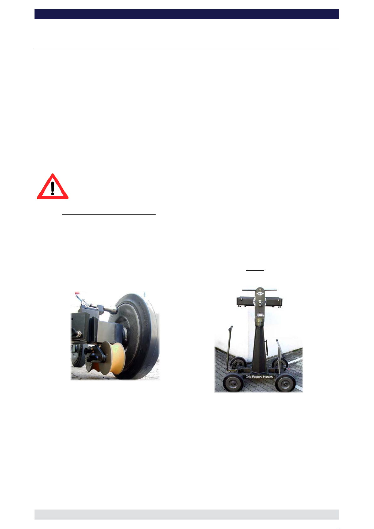
General Assembly Procedure – GF-8
General description:
The GF-8 and GF-8 Xten is a mobile crane-system for mounting cameras in a stationary
ground position or for movem ent on tr ac k.
It can be operated manually from the ground and can be panned in all directions either
with a remote-bracket or a 1 to 2 person platform. In accordance to the safety guidelines
the crane is only allowed to be used on solid, level and stable ground. While using it
stationary the levelling legs have to be used.
The crane operation from the ground is managed by at least one experienced, trained and
authorised personnel from the hand grips on the counterweight bucket.
Operation of the crane is only allowed within the limits and guidelines mentioned in the
instruction manual. The allowed payloads of each version are clearly shown on the
counterweight bucket (workplace of the crane operator).
Attention: Before and during assembly observe the Safety Guidelines.
For all GF-8 Standard-Versions:
1. Secure the base dolly so that it cannot move or roll. Lock all wheel brakes. Move the
steering rod towards the centre of the dolly or remove it so that the set-up personnel
do not trip over it.
2. For the Standard-Versions 1 to 8 bolt the 90cm crane mounting column to the base
dolly (pivot height 154cm). Make sure that the 4 locking bolts are locked securely.
Tip: The carrying handle on the bazooka should point away from the steering end
of the dolly.
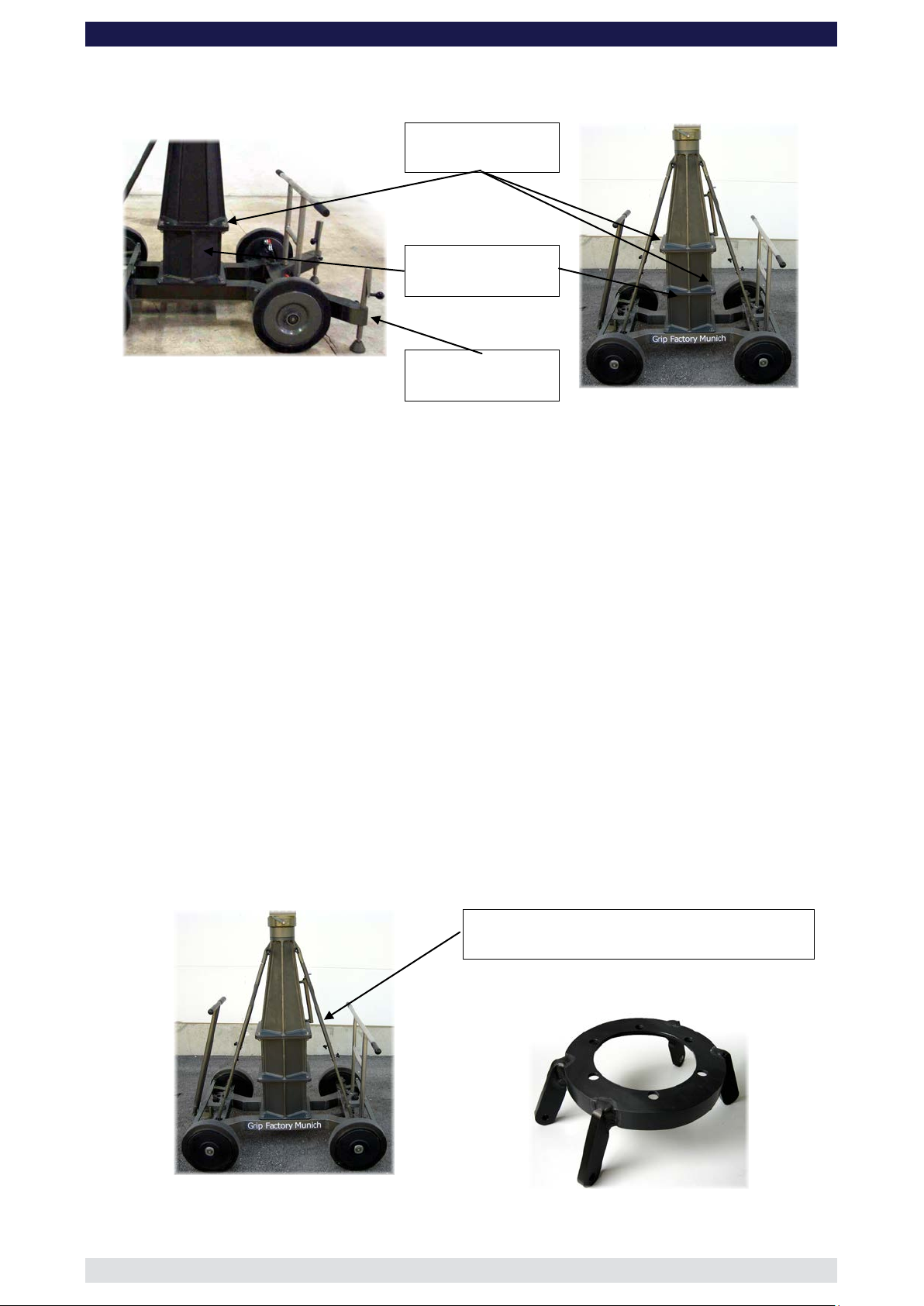
Wheel brake on Base Dolly
Base Dolly with 90cm / 3ft Mounting Column and
Pivot Section (Versions 1-8)
The 30cm / 1ft column extension is used in combination with the 90cm column for
versions 9 to 18 to increase the pivot height from 154cm to 184cm. It is connected to
the standard GF-8 column with 4 locking nuts and bolts. Make sure that the 4 locking
bolts are locked securely.
Page 6
8 Xten Crane System Instruction Manual
Page: 5
(2 x 30cm + 60cm Column sections) with Supports
Adapter ring for column supports
GF-
As an option a 3 stage column is also available. It consists of 2 x 30cm / 1ft column
extensions and a 60cm / 2ft Mounting Column. Assemble the column extension
between the column and the base dolly locking the 12 locking bolts securely.
Locking bolts
Column Extension
Base Dolly with 30cm / 1ft Column Extension
Extended levelling
legs
3 pivot heights are possible:
o 184cm / 6ft with all 3 parts (2 x 30cm / 1ft and 1 x 60cm) or with two parts (1 x
30cm / 1ft and 1 x 90cm / 3ft)
o 154cm / 5ft with a 30cm / 1ft column extensi on and 60cm / 2ft mounting
column
o 124cm / 4ft with 60cm / 2ft mounting column.
3. For Standard Versions 9 to 18 we recommend using the 4 telescopic column
supports. In smaller versions they are not required but using them does increase the
columns stability. To mount the supports connect the grooved end to the connection
on the column, securing with the locking pin. Remove the locking pin in the middle of
the column support enabling the rod to reach the connection on the base dolly and
secure with the locking pin. The locking pin previously removed from the centre of the
column support can now be reinserted to fix the length. Turn the grooved part in a
clockwise direction to apply tension.
Tip: Should the column not have the 4 connections for the column supports, an
adapter is available. It is connected to the column between the pan bearing
oder besser turnstile??? and the top of the column. To do so the pan bearing
must be removed by unscrewing the 6 screws. The adapter must be mounted
in line to the connections on the base dolly with the adapter ring connectors
pointing towards the base dolly. The original screws must be replaced by
5mm longer screws.
3 Stage Mounting Column
Telescopic Column Supports
Page 7
8 Xten Crane System Instruction Manual
Page: 6
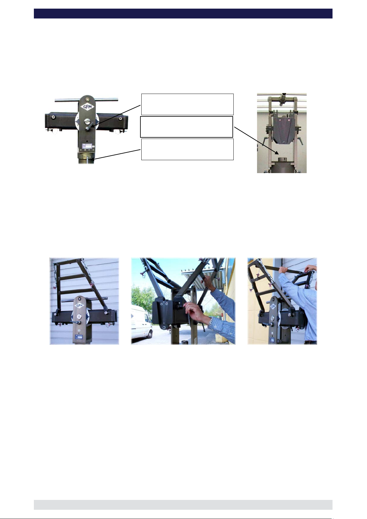
Middle section with pan and tilt lock
GF-
4. Located on the middle section are 2 tilt friction locks which may be used to lock the tilt
during set-up. Set the pivot arm at 90° to the centre post and lock these friction locks
which can be found on the left and right hand side of the middle section. Mount the
middle section on the mounting column. Lock the locking screw tightly.
Tip: A 12mm Allen key can be found in the mounting column’s handle to be used
as a lever.
Attention: Install the middle section to the rotateable bearing of the column with
positive locking. It fits properly only in one position.
Tilt brake
Locking screw
Pan brake
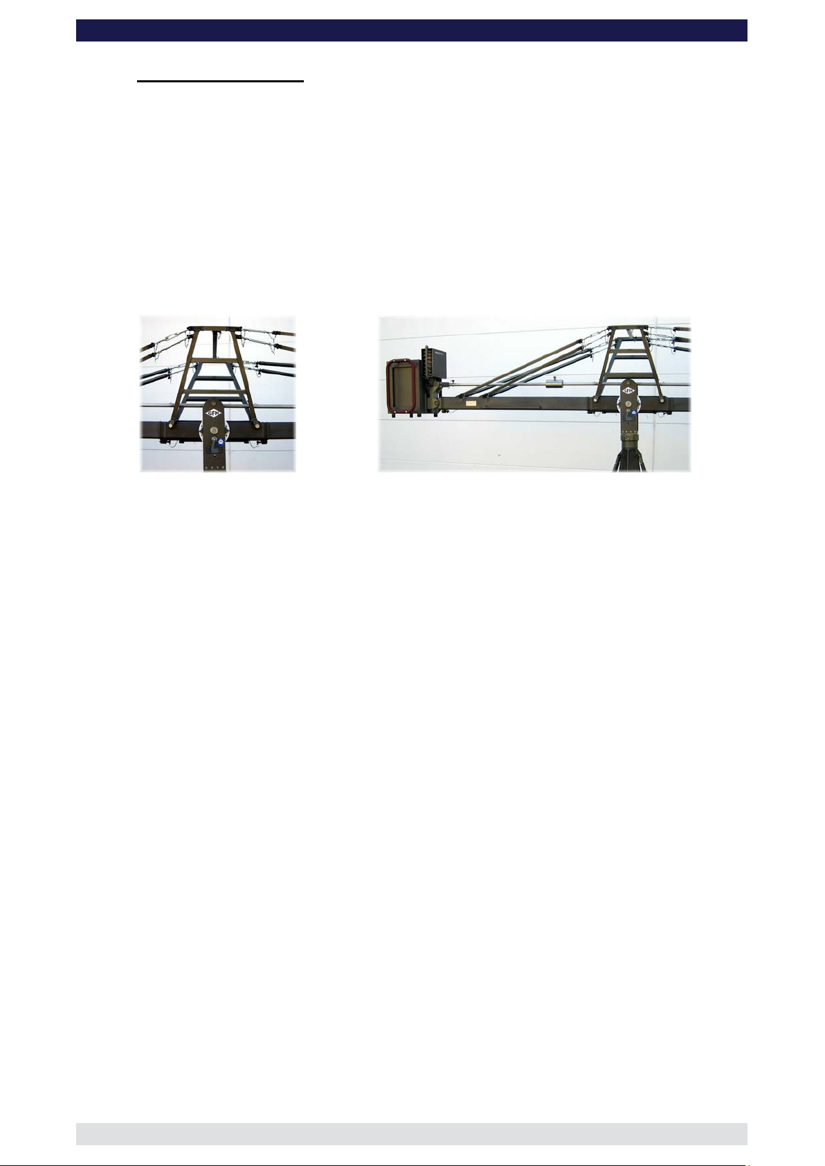
Unless otherwise stated it is required to use the rigging system when more than
1 x 150cm / 5ft section is mounted to the front of the crane i.e. all versions except
1 and 9.
5. Connect the 2 sections of the rigging harness to the middle section of the GF-8.
Ensure that the 4 locking bolts are fastened tightly.
6. Connect the cross bar to stabilize the rigging harness. Ensure that the 2 locking pins
are inserted fully.
7. For Standard Versions 1 to 16 connect the 127cm / 4ft rear arm section to the middle
section. For Standard Versions 17 and 18 connect the 150cm / 5ft section to the
middle section. Slip the connection flanges into each other and secure with the
provided safety pin.
Connect the respective 127cm or 150cm parallelogram rod to the middle section,
mount the sliding weight and secure with the locking screw. Other shorter versions
can be built by using the 100cm / 3’ 3” or 150cm / 5’ extension and its parallelogram
rod.
Tip: To avoid the sections jamming or getting stuck make sure that the sections
are joined parallel. Using a small amount of lubricant also helps. We suggest
rubbing the joints with an oiled rag.
Page 8

8 Xten Crane System Instruction Manual
Page: 7
Mounting an extension arm
Securing the arm with a safety pin
Mounting an angle adjuster
Securing with a safety pin
GF-
8. Connect one of the angle adjusters to the end of the 127cm / 4ft or 150cm / 5ft
section and secure it with the provided safety pin.
Attention: Pinch point
Integrated leveller
Tip: The angle adjuster has an integrated leveller. By turning it, the vertical plate
on the angle adjuster can be set to a perfect right angle. Correct setting of
the angle adjuster enhances t he crane’ s bal a nc e.
9. Depending on the version being assembled connect 2 of the respective rigging rods
to the turnbuckles on the rigging harness and in turn to the 2 connections on the arm
section leading to the weight bucket.
Arm section 127cm / 4ft = rigging rod 115cm / 3’ 9”
Arm section 150cm / 5ft = rigging rod 142cm / 4’ 7”
Hand tighten the rods by turning the turnbuckles until the rods are taut.
Tip: For easier assembly we recommend to support the arm of the crane with a
stable underlay.
Middle sized rigging rod
Page 9
8 Xten Crane System Instruction Manual
Page: 8
Large Rigging Harness for double Rigging
(Xten Versions 1 to 8)
(Xten-Versions 1 to 8)
GF-
For all GF-8 Xten-Versions:
With the exception of a few steps, the assembly of the Xten Versions are identical with
those of the Standard Versions. However, the following points should be followed:
o All Xten Versions require a pivot height of 184cm / 6ft as follows:
o 30cm / 1ft Column Extension and 90cm / 3ft Mounting Column
o 2 x 30cm / 1ft column extensions and a 60cm / 2ft Mounting Column
More details can be found on page 4.
o The Mounting Column for all Xten Versions (1 to 8) must be supported with the 4
Telescopic Column Supports. More details can be found on page 5.
o All Xten-Versions (1 to 8) require the Large Rigging Harness with the double
turnbuckles. An example of the assembly can be found on page 6.
o All Xten Versions (1 to 8) require the 160cm / 5’ 3“ rear arm extension as well as the
160cm / 5’ 3“ parallelogram rod to be mounted between the pivot and the angle
adjuster. Example of the assembly can be found on page 6 and 7.
o All Xten Versions (1 to 8) require a double rigging system. Connect the 142cm / 4’
7” rigging rods to the top turnbuckles and the outside connections on the rear
extension. Connect the 115cm / 3’ 9” rigging rods to the lower turnbuckles and the
inside connections on t he rear extension.
Double Rigging System with 160cm / 5’3“ Rear Extension
Page 10
8 Xten Crane System Instruction Manual
Page: 9
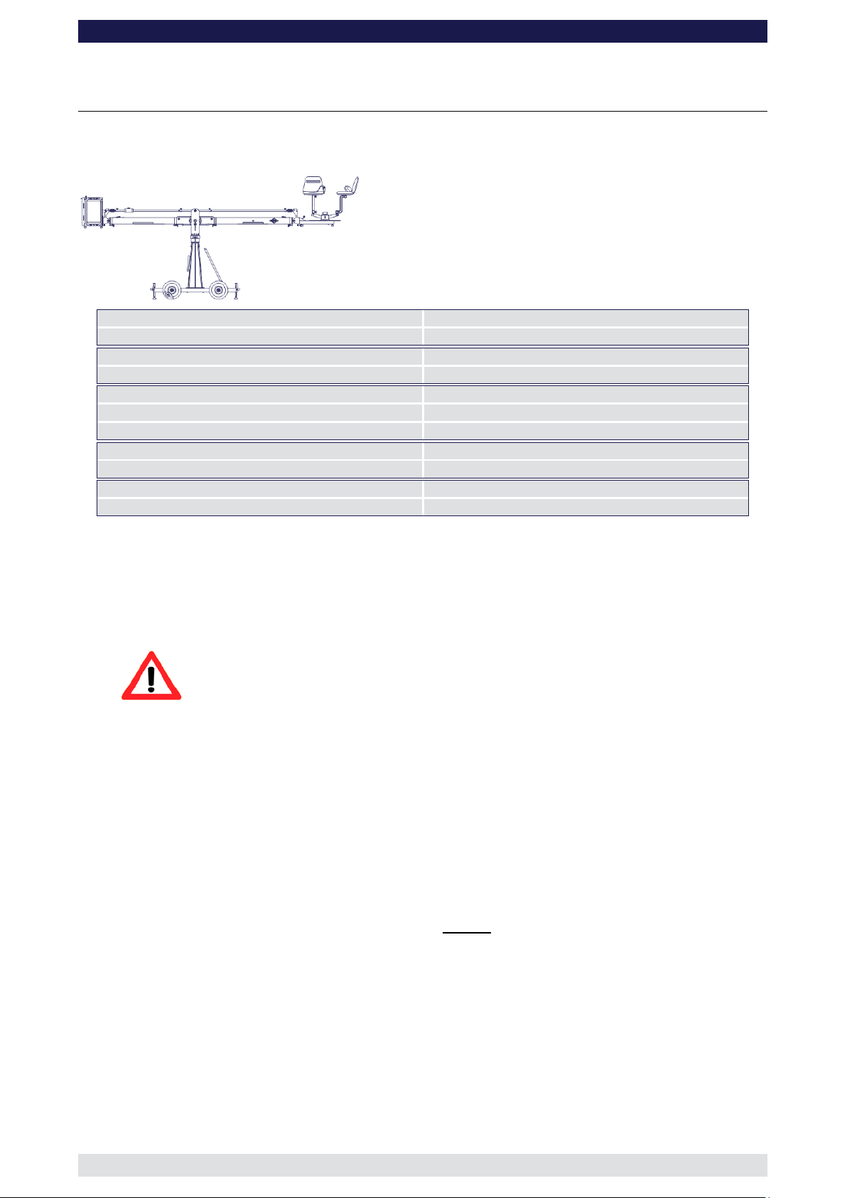
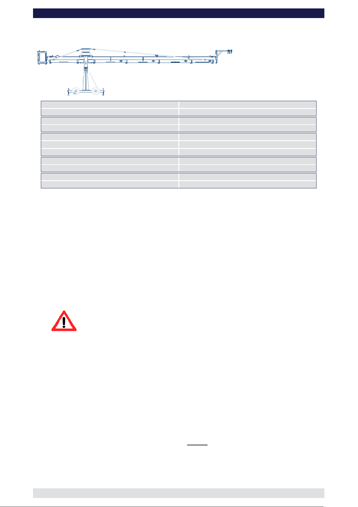
Front extension arms required
1 x 150 cm / 5’
Rear extension arm required
1 x 127 cm / 4’ 2”
Lift range
319 cm / 10’ 5”
Maximum Euro-adapter height
331 cm / 10’ 10“
Lift capacity (working load) 2 pers. + accessories
250 kg / 550 lbs
Counterweight required for max. load
276 kg / 607 lbs
Counterweight required to balanc e em pt y arm
0 kg / 0 lbs
Crane weight (excluding dolly and weights)
149 kg / 327 lbs
Dolly weight
80 kg / 176 lbs
Arm reach (pivot to camera head mount)
253 cm / 8’ 3“
Length of rear end (pivot to outside of bucket)
220 cm / 7’ 2“
GF-
Assembly & Technical Spec if ication Version 1 to 18
Version 1
(Pivot height 154cm / 5ft, Rear Extension 127cm / 4’ 2”)
Continue from § 9, page 7
10. Connect one of the 150cm / 5’ sections to the middle section. Slip the connection
flanges into each other and secure them with the provided safety pin.
11. Connect the remaining angle adjuster to the end of the 150cm / 5’ section and secure
it with the provided safety pin.
Attention: Pinch point
12. Connect one of the 150cm / 5’ parallelogram rods to the middle section and the angle
adjuster and secure it with a safety pin at each end.
13. Connect the platform to the angle adjuster by inserting the male platform flange into
the female flange on the angle adjuster. Secure it with the safety pin.
14. Attach the weight bucket to the short end of the crane by inserting the male weight
bucket flange into the female flange on the angle adjuster. Secure it with the 2 safety
pins on the top of the angle adjuster.
Tip: The angle adjuster has an integrated leveller. By turning it, the vertical plate
on the angle adjuster can be set to a perfect right angle. Correct setting of
the angle adjuster enhances the crane’s balance. Level the weight bucket,
the platform or the remote brack et before loading any weights.
Before operation, all locking pins , loc king scr ews etc should be inspe cted to e nsure
that all assembly sections are securely fastened.
Page 11
8 Xten Crane System Instruction Manual
Page: 10
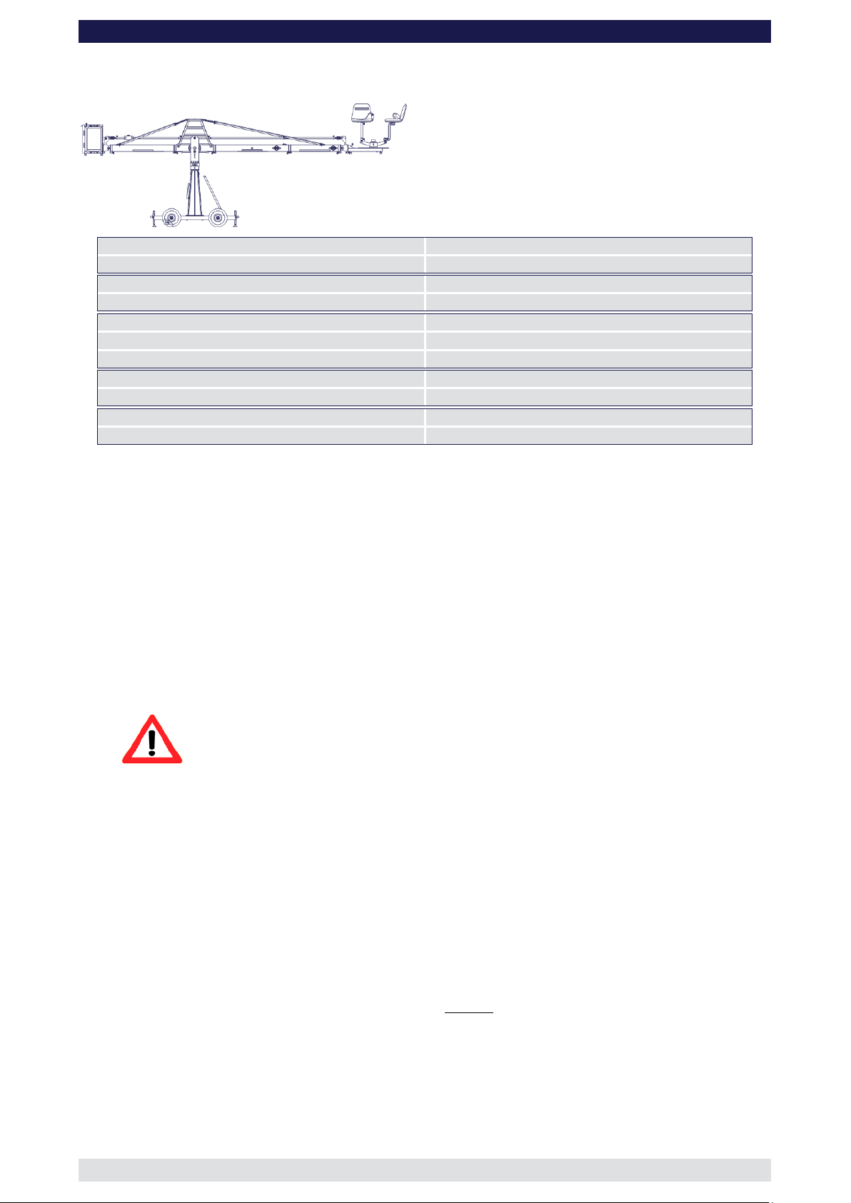
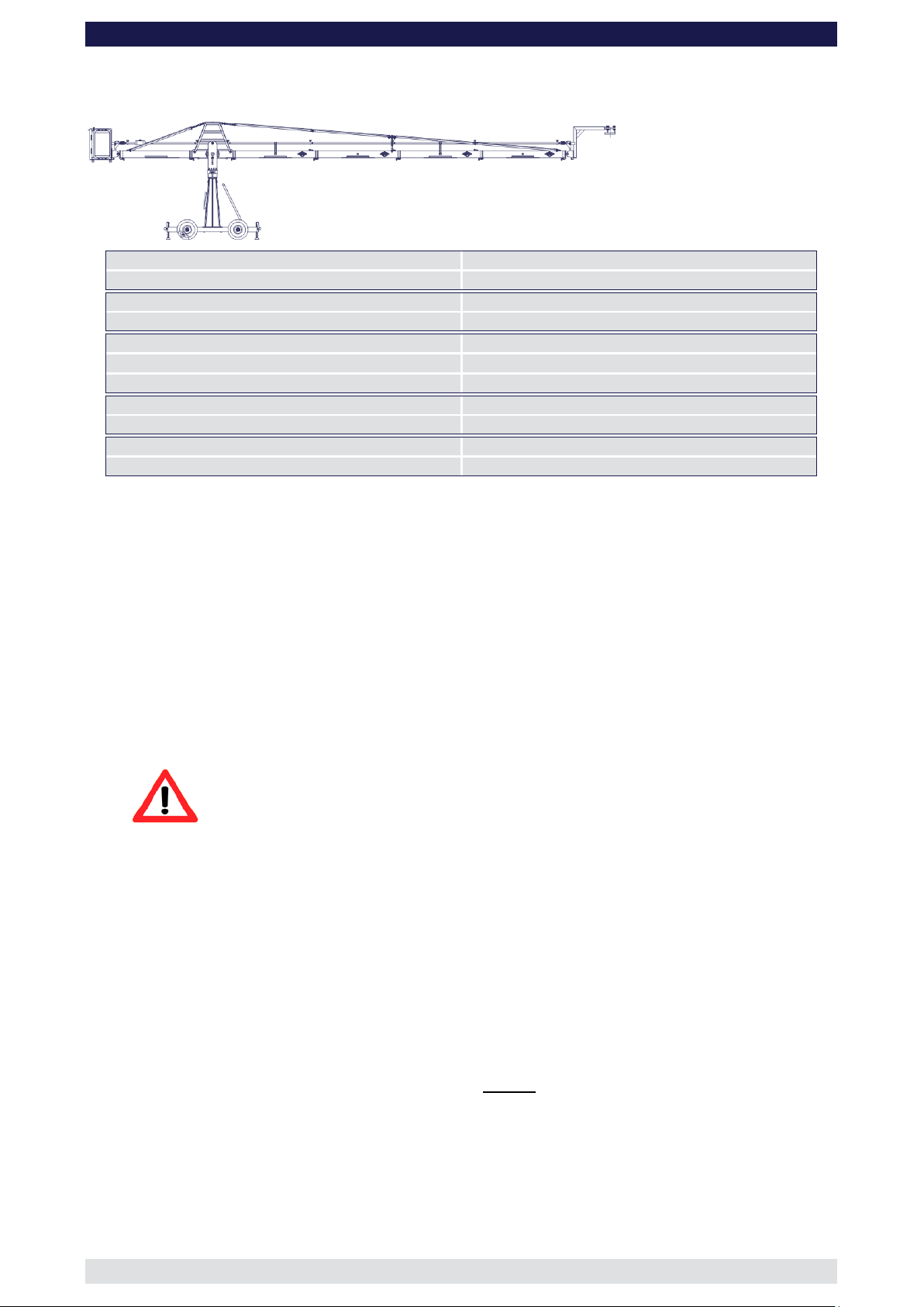
Front extension arms required
1 x 150 cm / 5’ + 100 cm / 3’ 3”
Rear extension arm required
1 x 127 cm / 4’ 2”
Lift range
481 cm / 15’ 9”
Maximum Euro-adapter height
412 cm / 13’ 5“
Lift capacity (working load) 2 pers. + accessories
250 kg / 550 lbs
Counterweight required for max. load
456 kg / 1003 lbs
Counterweight required to balance empty arm
28 kg / 61 lbs
Crane weight (excluding dolly and weights)
173 kg / 380 lbs
Dolly weight
80 kg / 176 lbs
Arm reach (pivot to camera head mount)
351 cm / 11’ 5“
Length of rear end (pivot to outside of bucket)
220 cm / 7’ 2“
GF-
Version 2
(Pivot height 154cm / 5ft, Standard Rigging Harness, Rear Extension 127cm / 4’ 2”)
Rigging is required! Observe guidelines on page 41.
Continue from § 9, page 7
10. Connect one of the 150cm / 5’ sections to the middle section. Slip the connection
flanges into each other and secure them with the provi ded sa fety pin.
11. Connect the 100cm / 3’ 3” section to the 150cm / 5’ section. Slip the connection
flanges into each other and secure them with the provided safety pin.
Note: After each mounted section the support stand or rostrum can be moved up to
the next fixed section. We recommend to support longer crane versions with
more than one support stand or rostrum.
12. Connect the remaining angle adjuster to the end of the 100cm / 3’ 3” section and
secure it with the provided safety pin.
Attention: Pinch point
13. Connect a 150cm / 5’ as well as a 100cm / 3’ 3” parallelogram rod to the middle
section and in turn to the angle adjuster and secure the connections with the provided
safety pins.
14. Connect the platform to the angle adjuster by inserting the male platform flange into
the female flange on the angle adjuster. Secure it with the safety pin.
15. Attach the weight bucket to the short end of the crane by inserting the male weight
bucket flange into the female flange on the angle adjuster. Secure it with the 2 safety
pins on the top of the angle adjuster.
Tip: The angle adjuster has an integrated leveller. By turning it, the vertical plate
on the angle adjuster can be set to a perfect right angle. Correct setting of
the angle adjuster enhances the crane’s balance. Level the weight bucket,
the platform or the remote brack et before loading any weights.
16. Now the standard rigging system can be assembled. Therefor follow the instructions
as exemplary shown by version 17 and 18 on page 41.
Before operation, all locking pins, locking screws etc should be inspe cted to e nsure
that all assembly sections are securely fastened.
Page 12

8 Xten Crane System Instruction Manual
Page: 11
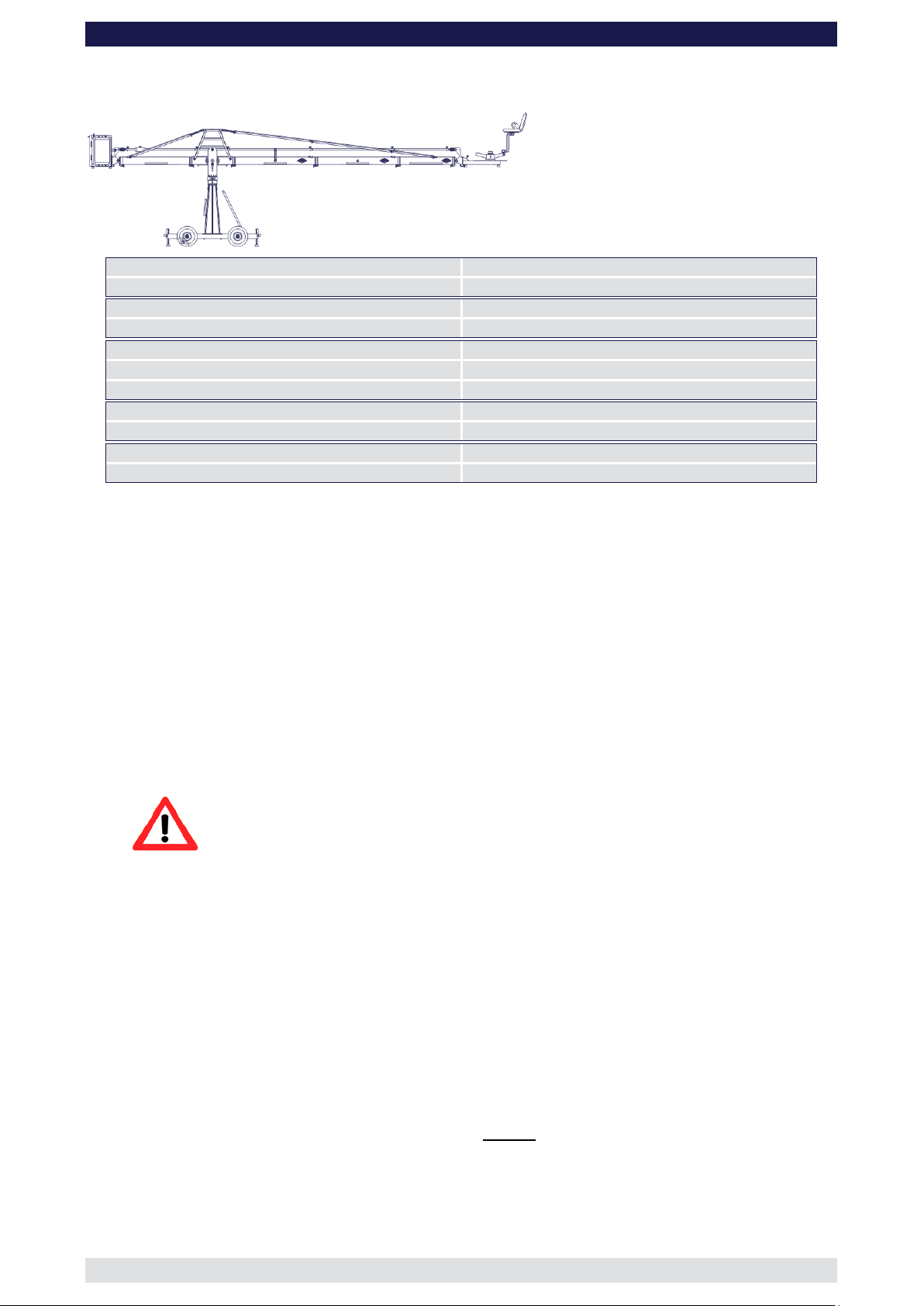
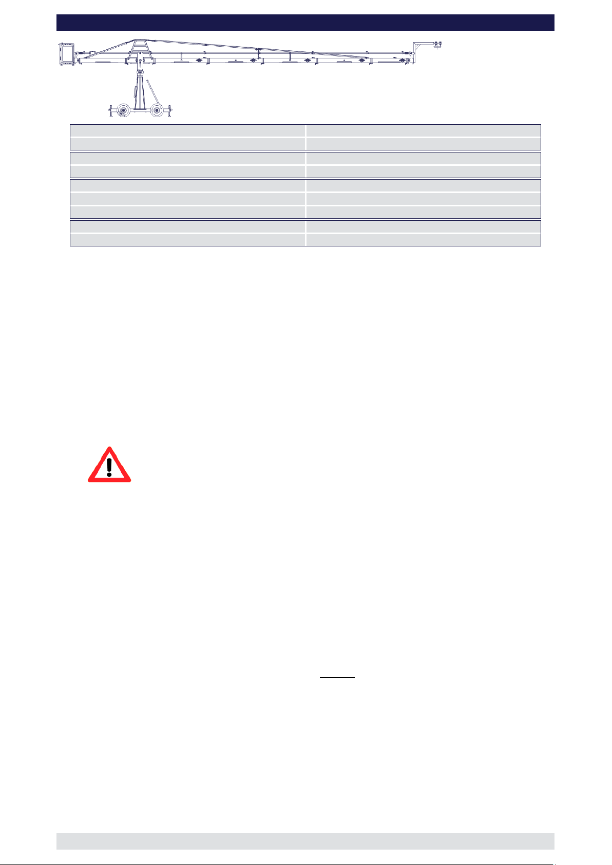
Front extension arms required
2 x 150 cm / 5’
Rear extension arm required
1 x 127 cm / 4’ 2”
Lift range
564 cm / 18’ 6”
Maximum Euro-adapter height
453 cm / 14’ 10“
Lift capacity (working load) 2 pers. + accessories
216 kg / 475 lbs
Counterweight required for max. load
480 kg / 1056 lbs
Counterweight required to bal ance em pty arm
46 kg / 101 lbs
Crane weight (excluding dolly and weights)
179 kg / 393 lbs
Dolly weight
80 kg / 176 lbs
Arm reach (pivot to camera head mount)
401 cm / 13’ 1“
Length of rear end (pivot to outside of bucket)
220 cm / 7’ 2“
GF-
Version 3
(Pivot height 154cm / 5ft, Standard Rigging Harness, Rear Extension 127cm / 4’ 2”)
Rigging is required! Observe guidelines on page 41.
Continue from § 9, page 7
10. Connect one of the 150cm / 5’ sections to the middle section. Slip the connection
flanges into each other and secure them with the provided safety pin.
11. Connect another 150cm / 5’ section to the first 150cm / 5’ section. Slip the connection
flanges into each other and secure them with the provided safety pin.
Note: After each mounted section the support stand or rostrum can be moved up to
the next fixed section. We recommend to support longer crane versions with
more than one support stand or rostrum.
12. Connect the remaining angle adjuster to the end of the second 150cm / 5’ section and
secure it with the provided safety pin.
Attention: Pinch point
13. Mount the parallelogram rod support to the respective section as shown on page 40.
14. Connect two 150cm / 5’ parallelogram rods to the middle section and in turn to the
angle adjuster and secure the connections with the provided safety pins.
15. Connect the platform to the angle adjuster by inserting the male platform flange into
the female flange on the angle adjuster. Secure it with the safety pin.
16. Attach the weight bucket to the short end of the crane by inserting the male weight
bucket flange into the female flange on the angle adjuster. Secure it with the 2 safety
pins on the top of the angle adjuster.
Tip: The angle adjuster has an integrated leveller. By turning it, the vertical plate
on the angle adjuster can be set to a perfect right angle. Correct setting of
the angle adjuster enhances the crane’s balance. Level the weight bucket,
the platform or the remote brack et before loading any weights.
17. Now the standard rigging system can be assembled. Therefor follow the instructions
as exemplary shown by version 17 and 18 on page 41.
Before operation, all locking pins , loc king scr ews etc should be inspe cted to e nsure
that all assembly sections are securely fastened.
Page 13
8 Xten Crane System Instruction Manual
Page: 12
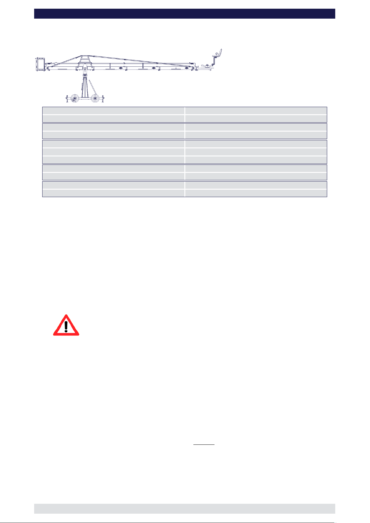
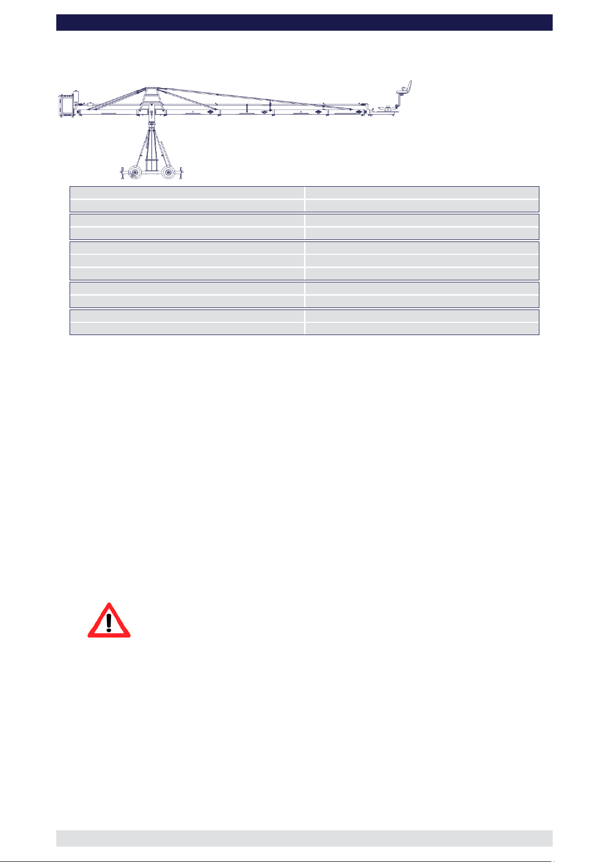
Front extension arms required
2 x 150 cm / 5’ + 100 cm / 3’ 3”
Rear extension arm required
1 x 127 cm / 4’ 2”
Lift range
727 cm / 23’ 9”
Maximum Euro-adapter height
534 cm / 17’ 6“
Lift capacity (working load) 1 pers. + accessories
150 kg / 330 lbs
Counterweight required for max. load
480 kg / 1056 lbs
Counterweight required to balanc e em pt y arm
88 kg / 176 lbs
Crane weight (excluding dolly and weights)
191 kg / 420 lbs
Dolly weight
80 kg / 176 lbs
Arm reach (pivot to camera head mount)
498 cm / 16’ 4“
Length of rear end (pivot to outside of bucket)
220 cm / 7’ 2“
GF-
Version 4
(Pivot height 154cm / 5ft, Standard Rigging Harness, Rear Extension 127cm / 4’ 2”)
Rigging is required! Observe guidelines on page 41.
Continue from § 9, page 7
10. Connect one of the 150cm / 5’ sections to the middle section. Slip the connection
flanges into each other and secure them with the provided safety pin.
11. Connect another 150cm / 5’ and a 100cm / 3’ 3” section to the first 150cm / 5’ section.
Slip the connection flanges into each other and secure them with the provided safety
pin.
Note: After each mounted section the support stand or rostrum can be moved up to
the next fixed section. We recommend to support longer crane versions with
more than one support stand or rostrum.
12. Connect the remaining angle adjuster to the end of the 100cm / 3’ 3” section and
secure it with the provided safety pin.
Attention: Pinch point
13. Mount the parallelogram rod support to the respective section as shown on page 40.
14. Connect two 150cm / 5’ parallelogram rods and a 100cm / 3’ 3” rod to the middle
section and in turn to the angle adjuster and secure the connections with the provided
safety pins.
15. Connect the platform to the angle adjuster by inserting the male platform flange into
the female flange on the angle adjuster. Secure it with the safety pin.
16. Attach the weight bucket to the short end of the crane by inserting the male weight
bucket flange into the female flange on the angle adjuster. Secure it with the 2 safety
pins on the top of the angle adjuster.
Tip: The angle adjuster has an integrated leveller. By turning it, the vertical plate
on the angle adjuster can be set to a perfect right angle. Correct setting of
the angle adjuster enhances the crane’s balance. Level the weight bucket,
the platform or the remote brack et before loading any weights.
17. Now the standard rigging system can be assembled. Therefor follow the instructions
as exemplary shown by version 17 and 18 on page 41.
Before operation, all locking pins , loc king scr ews etc should be inspe cted to e nsure
that all assembly sections are securely fastened.
Page 14
8 Xten Crane System Instruction Manual
Page: 13
Front extension arms required
3 x 150 cm / 5’
Rear extension arm required
1 x 127 cm / 4’ 2”
Lift range
809 cm / 30’ 7”
Maximum Euro-adapter height
576 cm / 18’ 10“
Lift capacity (working load) 1 pers. + accessories
128 kg / 281 lbs
Counterweight required for max. load
480 kg / 1056 lbs
Counterweight required to bala nce empty arm
112 kg / 246 lbs
Crane weight (excluding dolly and weights)
197 kg / 433 lbs
Dolly weight
80 kg / 176 lbs
Arm reach (pivot to camera head mount)
549 cm / 18’
Length of rear end (pivot to outside of bucket)
220 cm / 7’ 2“
GF-
Version 5
(Pivot height 154cm / 5ft, Standard Rigging Harness, Rear Extension 127cm / 4’ 2”)
Rigging is required! Observe guidelines on page 41.
Continue from § 9, page 7
10. Connect one of the 150cm / 5’ sections to the middle section. Slip the connection
flanges into each other and secure them with the provided safety pin.
11. Connect another two 150cm / 5’ sections to the first 150cm / 5’ section. Slip the
connection flanges into each other and secure them with the provided safety pins.
Note: After each mounted section the support stand or rostrum can be moved up to
the next fixed section. We recommend to support longer crane versions with
more than one support stand or rostrum.
12. Connect the remaining angle adjuster to the end of the last 150cm / 5’ section and
secure it with the provided safety pin.
Attention: Pinch point
13. Mount the parallelogram rod support to the respective section as shown on page 40.
14. Connect three 150cm / 5’ parallelogram rods to the middle section and in turn to the
angle adjuster and secure the connections with the provided safety pins.
15. Connect the platform to the angle adjuster by inserting the male platform flange into
the female flange on the angle adjuster. Secure it with the safety pin.
16. Attach the weight bucket to the short end of the crane by inserting the male weight
bucket flange into the female flange on the angle adjuster. Secure it with the 2 safety
pins on the top of the angle adjuster.
Tip: The angle adjuster has an integrated leveller. By turning it, the vertical plate
on the angle adjuster can be set to a perfect right angle. Correct setting of
the angle adjuster enhances the crane’s balance. Level the weight bucket,
the platform or the remote brack et before loading any weights.
17. Now the standard rigging system can be assembled. Therefor follow the instructions
as exemplary shown by version 17 and 18 on page 41.
Before operation, all locking pins , loc king scr ews etc should be inspe cted to e nsure
that all assembly sections are securely fastened.
Page 15
8 Xten Crane System Instruction Manual
Page: 14
Front extension arms required
3 x 150 cm / 5’ + 100 cm / 3’ 3”
Rear extension arm required
1 x 127 cm / 4’ 2”
Lift range
891 cm / 31’ 10”
Maximum Euro-adapter height
675 cm / 22’ 1“
Lift capacity
80 kg / 176 lbs
Counterweight required for max. load
420 kg / 924 lbs
Counterweight required to balanc e em pt y arm
140 kg / 308 lbs
Crane weight (excluding dolly and weights)
199 kg / 437 lbs
Dolly weight
80 kg / 176 lbs
Arm reach (pivot to camera head mount)
663 cm / 21’ 8“
Length of rear end (pivot to outside of bucket)
220 cm / 7’ 2“
GF-
Version 6
(Pivot height 154cm / 5ft, Standard Rigging Harness, Rear Extension 127cm / 4’ 2”)
Rigging is required! Observe guidelines on page 41.
Continue from § 9, page 7
10. Connect one of the 150cm / 5’ sections to the middle section. Slip the connection
flanges into each other and secure them with the provided safety pin.
11. Connect another two 150cm / 5’ sections and a 100cm / 3’ 3” section to the first
150cm / 5’ section. Slip the connection flanges into each other and secure them with
the provided safety pins.
Note: After each mounted section the support stand or rostrum can be moved up to
the next fixed section. We recommend to support longer crane versions with
more than one support stand or rostrum.
12. Connect the remaining angle adjuster to the end of the 100cm / 3’ 3” section and
secure it with the provided safety pin.
Attention: Pinch point
13. Mount the parallelogram rod support to the respective section as shown on page 40.
14. Connect three 150cm / 5’ parallelogram rods and a 100cm / 3’ 3” rod to the middle
section and in turn to the angle adjuster and secure the connections with the provided
safety pins.
15. Connect the remote bracket to the angle adjuster by inserting the male flange into the
female flange on the angle adjuster. Secure it with the safety pin.
16. Attach the weight bucket to the short end of the crane by inserting the male weight
bucket flange into the female flange on the angle adjuster. Secure it with the 2 safety
pins on the top of the angle adjuster.
Tip: The angle adjuster has an integrated leveller. By turning it, the vertical plate
on the angle adjuster can be set to a perfect right angle. Correct setting of
the angle adjuster enhances the crane’s balance. Level the weight bucket,
the platform or the remote brack et before loading any weights.
17. Now the standard rigging system can be assembled. Therefor follow the instructions
as exemplary shown by version 17 and 18 on page 41.
Before operation, all locking pins , loc king scr ews etc should be inspe cted to e nsure
that all assembly sections are securely fastened.
Page 16
8 Xten Crane System Instruction Manual
Page: 15
Front extension arms required
4 x 150 cm / 5’
Rear extension arm required
1 x 127 cm / 4’ 2”
Lift range
1054 cm / 34’ 6”
Maximum Euro-adapter height
716 cm / 23’ 5“
Lift capacity
80 kg / 176 lbs
Counterweight required for max. load
476 kg / 1047 lbs
Counterweight required to balanc e em pt y arm
172 kg / 378 lbs
Crane weight (excluding dolly and weights)
206 kg / 453 lbs
Dolly weight
80 kg / 176 lbs
Arm reach (pivot to camera head mount)
713 cm / 23’ 4“
Length of rear end (pivot to outside of bucket)
220 cm / 7’ 2“
GF-
Version 7
(Pivot height 154cm / 5ft, Standard Rigging Harness, Rear Extension 127cm / 4’ 2”)
Rigging is required! Observe guidelines on page 41.
Continue from § 9, page 7
10. Connect one of the 150cm / 5’ sections to the middle section. Slip the connection
flanges into each other and secure them with the provided safety pin.
11. Connect another three 150cm / 5’ sections to the first 150cm / 5’ section. Slip the
connection flanges into each other and secure them with the provided safety pins.
Note: After each mounted section the support stand or rostrum can be moved up to
the next fixed section. We recommend to support longer crane versions with
more than one support stand or rostrum.
12. Connect the remaining angle adjuster to the end of the last 150cm / 5’ section and
secure it with the provided safety pin.
Attention: Pinch point
13. Mount the parallelogram rod support to the respective section as shown on page 40.
14. Connect four 150cm / 5’ parallelogram rods to the middle section and in turn to the
angle adjuster and secure the connections with the provided safety pins.
15. Connect the remote bracket to the angle adjuster by inserting the male flange into the
female flange on the angle adjuster. Secure it with the safety pin.
16. Attach the weight bucket to the short end of the crane by inserting the male weight
bucket flange into the female flange on the angle adjuster. Secure it with the 2 safety
pins on the top of the angle adjuster.
Tip: The angle adjuster has an integrated leveller. By turning it, the vertical plate
on the angle adjuster can be set to a perfect right angle. Correct setting of
the angle adjuster enhances the crane’s balance. Level the weight bucket,
the platform or the remote brack et before loading any weights.
17. Now the standard rigging system can be assembled. Therefor follow the instructions
as exemplary shown by version 17 and 18 on page 41.
Before operation, all locking pins , locking screws etc should be inspe cted to ens ure
that all assembly sections are securely fastened.
Version 8
(Pivot height 154cm / 5ft, Standard Rigging Harness, Rear Extension 127cm / 4’ 2”)
Page 17
8 Xten Crane System Instruction Manual
Page: 16
Front extension arms required
4 x 150 cm / 5’ + 100 cm / 3’ 3”
Rear extension arm required
1 x 127 cm / 4’ 2”
Lift range
1216 cm / 39’ 10”
Maximum Euro-adapter height
798 cm / 16’ 2“
Lift capacity
50 kg / 110 lbs
Counterweight required for max. load
480 kg / 1056 lbs
Counterweight required to balance empty arm
288 kg / 501 lbs
Crane weight (excluding dolly and weights)
217 kg / 477 lbs
Arm reach (pivot to camera head mount)
810 cm / 26’ 6“
GF-
Rigging is required! Observe guidelines on page 41.
Continue from § 9, page 7
10. Connect one of the 150cm / 5’ sections to the middle section. Slip the connection
flanges into each other and secure them with the provided safety pin.
11. Connect another three 150cm / 5’ sections and a 100cm / 3’ 3” section to the first
150cm / 5’ section. Slip the connection flanges into each other and secure them with
the provided safety pins.
Note: After each mounted section the support stand or rostrum can be moved up to
the next fixed section. We recommend to support longer crane versions with
more than one support stand or rostrum.
12. Connect the remaining angle adjuster to the end of the 100cm / 3’ 3” section and
secure it with the provided safety pin.
Attention: Pinch point
13. Mount the parallelogram rod support to the respective section as shown on page 40.
14. Connect four 150cm / 5’ parallelogram rods and a 100cm / 3’ 3” rod to the middle
section and in turn to the angle adjuster and secure the connections with the provided
safety pins.
15. Connect the remote bracket to the angle adjuster by inserting the male flange into the
female flange on the angle adjuster. Secure it with the safety pin.
16. Attach the weight bucket to the short end of the crane by inserting the male weight
bucket flange into the female flange on the angle adjuster. Secure it with the 2 safety
pins on the top of the angle adjuster.
Tip: The angle adjuster has an integrated leveller. By turning it, the vertical plate
on the angle adjuster can be set to a perfect right angle. Correct setting of
the angle adjuster enhances the crane’s balance. Level the weight bucket,
the platform or the remote brack et before loading any weights.
17. Now the standard rigging system can be assembled. Therefor follow the instructions
as exemplary shown by version 17 and 18 on page 41.
Before operation, all locking pins, locking s crew s etc shoul d be ins pec ted to ens ure
that all assembly sections are securely fastened.
Page 18

8 Xten Crane System Instruction Manual
Page: 17
Front extension arms required
1 x 150 cm / 5’
Rear extension arm required
1 x 127 cm / 4’ 2”
Lift range
319 cm / 10’ 5”
Maximum Euro-adapter height
361 cm / 11’ 10“
Lift capacity
250 kg / 550 lbs
Counterweight required for max. load
276 kg / 607 lbs
Counterweight required to balanc e em pt y arm
0 kg / 0 lbs
Crane weight (excluding dolly and weights)
160 kg / 352 lbs
Dolly weight
80 kg / 176 lbs
Arm reach (pivot to camera head mount)
253 cm / 8’ 3“
Length of rear end (pivot to outside of bucket)
220 cm / 7’ 2“
Front extension arms required
1 x 150 cm / 5’ + 100 cm / 3’ 3”
Rear extension arm required
1 x 127 cm / 4’ 2”
Lift range
481 cm / 15’ 9”
Maximum Euro-adapter height
442 cm / 14’ 5“
Lift capacity
250 kg / 550 lbs
Counterweight required for max. load
456 kg / 1003 lbs
Counterweight required to bal ance em pty arm
28 kg / 61 lbs
Crane weight (excluding dolly and weights)
184 kg / 404 lbs
Dolly weight
80 kg / 176 lbs
Arm reach (pivot to camera head mount)
351 cm / 11’ 5“
Length of rear end (pivot to outside of bucket)
220 cm / 7’ 2“
GF-
Attention: The following versions 9 to 16 require a 127cm / 4’ 2” section to the rear
i.e. Counterweight Bucket End.
The 30cm / 1ft Column Extension is also required to achieve a pivot
height to 184cm / 6ft. See page 4.
Version 9
(Pivot height 184cm / 6ft, Rear Extension 127cm / 4’ 2”)
Assemble the GF-8 Column Extension as per the instructions on page 4.
The GF-8 version 9 is assembled in the same manner as version 1.
Version 10
(Pivot height 184cm / 6ft, Standard Rigging Harness, Rear Extension 127cm / 4’ 2”)
Assemble the GF-8 Column Extension as per the instructions on page 4.
The GF-8 version 10 is assembled in the same manner as version 2.
Page 19

8 Xten Crane System Instruction Manual
Page: 18
Front extension arms required
2 x 150 cm / 5’
Rear extension arm required
1 x 127 cm / 4’ 2”
Lift range
564 cm / 18’ 6”
Maximum Euro-adapter height
483 cm / 15’ 10“
Lift capacity
216 kg / 475 lbs
Counterweight required for max. load
480 kg / 1056 lbs
Counterweight required to balanc e em pt y arm
46 kg / 101 lbs
Crane weight (excluding dolly and weights)
190 kg / 418 lbs
Dolly weight
80 kg / 176 lbs
Arm reach (pivot to camera head mount)
401 cm / 13’ 1“
Length of rear end (pivot to outside of bucket)
220 cm / 7’ 2“
Front extension arms required
2 x 150 cm / 5’ + 100 cm / 3’ 3”
Rear extension arm required
1 x 127 cm / 4’ 2”
Lift range
727 cm / 23’ 9”
Maximum Euro-adapter height
564 cm / 18’ 6“
Lift capacity
150 kg / 330 lbs
Counterweight required for max. load
480 kg / 1056 lbs
Counterweight required to balanc e em pt y arm
88 kg / 176 lbs
Crane weight (excluding dolly and weights)
202 kg / 444 lbs
Dolly weight
80 kg / 176 lbs
Arm reach (pivot to camera head mount)
498 cm / 16’ 4“
Length of rear end (pivot to outside of bucket)
220 cm / 7’ 2“
GF-
Version 11
(Pivot height 184cm / 6ft, Standard Rigging Harness, Rear Extension 127cm / 4’ 2”)
Assemble the GF-8 Column Extension as per the instructions on page 4.
The GF-8 version 11 is assembled in the same manner as version 3.
Version 12
(Pivot height 184cm / 6ft, Standard Rigging Harness, Rear Extension 127cm / 4’ 2”)
Assemble the GF-8 Column Extension as per the instructions on page 4.
The GF-8 version 12 is assembled in the same manner as version 4.
Version 13
(Pivot height 184cm / 6ft, Standard Rigging Harness, Rear Extension 127cm / 4’ 2”)
Page 20

8 Xten Crane System Instruction Manual
Page: 19
Front extension arms required
3 x 150 cm / 5’
Rear extension arm required
1 x 127 cm / 4’ 2”
Lift range
809 cm / 30’ 7”
Maximum Euro-adapter height
606 cm / 19’ 10“
Lift capacity
128 kg / 281 lbs
Counterweight required for max. load
480 kg / 1056 lbs
Counterweight required to balanc e em pt y arm
112 kg / 246 lbs
Crane weight (excluding dolly and weights)
208 kg / 457 lbs
Dolly weight
80 kg / 176 lbs
Arm reach (pivot to camera head mount)
549 cm / 18’
Length of rear end (pivot to outside of bucket)
220 cm / 7’ 2“
Front extension arms required
3 x 150 cm / 5’ + 100 cm / 3’ 3”
Rear extension arm required
1 x 127 cm / 4’ 2”
Lift range
891 cm / 31’ 10”
Maximum Euro-adapter height
705 cm / 23’ 1“
Lift capacity
80 kg / 176 lbs
Counterweight required for max. load
420 kg / 924 lbs
Counterweight required to balanc e em pt y arm
140 kg / 308 lbs
Crane weight (excluding dolly and weights)
210 kg / 462 lbs
Dolly weight
80 kg / 176 lbs
Arm reach (pivot to camera head mount)
663 cm / 21’ 8“
Length of rear end (pivot to outside of bucket)
220 cm / 7’ 2“
GF-
Assemble the GF-8 Column Extension as per the instructions on page 4.
The GF-8 version 13 is assembled in the same manner as version 5.
Version 14
(Pivot height 184cm / 6ft, Standard Rigging Harness, Rear Extension 127cm / 4’ 2”)
Assemble the GF-8 Column Extension as per the instructions on page 4.
The GF-8 version 14 is assembled in the same manner as version 6.
Version 15
(Pivot height 184cm / 6ft, Standard Rigging Harness, Rear Extension 127cm / 4’ 2”)
Page 21

8 Xten Crane System Instruction Manual
Page: 20
Front extension arms required
4 x 150 cm / 5’
Rear extension arm required
1 x 127 cm / 4’ 2”
Lift range
1054 cm / 34’ 6”
Maximum Euro-adapter height
747 cm / 24’ 5“
Lift capacity
80 kg / 176 lbs
Counterweight required for max. load
476 kg / 1047 lbs
Counterweight required to balanc e em pt y arm
172 kg / 378 lbs
Crane weight (excluding dolly and weights)
217 kg / 477 lbs
Dolly weight
80 kg / 176 lbs
Arm reach (pivot to camera head mount)
713 cm / 23’ 4“
Length of rear end (pivot to outside of bucket)
220 cm / 7’ 2“
Front extension arms required
4 x 150 cm / 5’ + 100 cm / 3’ 3”
Rear extension arm required
1 x 127 cm / 4’ 2”
Lift range
1216 cm / 39’ 10”
Maximum Euro-adapter height
828 cm / 27’ 2“
Lift capacity
50 kg / 110 lbs
Counterweight required for max. load
480 kg / 1056 lbs
Counterweight required to bal ance em pty arm
288 kg / 501 lbs
Crane weight (excluding dolly and weights)
288 kg / 501 lbs
Dolly weight
80 kg / 176 lbs
Arm reach (pivot to camera head mount)
810 cm / 26’ 6“
Length of rear end (pivot to outside of bucket)
220 cm / 7’ 2“
GF-
Assemble the GF-8 Column Extension as per the instructions on page 4.
The GF-8 version 15 is assembled in the same manner as version 7.
Version 16
(Pivot height 184cm / 6ft, Standard Rigging Harness, Rear Extension 127cm / 4’ 2”)
Assemble the GF-8 Column Extension as per the instructions on page 4.
The GF-8 version 16 is assembled in the same manner as version 8.
Page 22

8 Xten Crane System Instruction Manual
Page: 21
Front extension arms required
4 x 150 cm / 5’ + 127 cm / 4’ 2”
Rear extension arm required
1 x 150 cm / 5’
Lift range
1216 cm / 39’ 10”
Maximum Euro-adapter height
850 cm / 27’ 10“
Lift capacity
50 kg / 110 lbs
Counterweight required for max. load
418 kg / 919 lbs
Counterweight required to balanc e em pt y arm
214 kg / 470 lbs
Crane weight (excluding dolly and weights)
239 kg / 525 lbs
Arm reach (pivot to camera head mount)
837 cm / 27’ 5“
Length of rear end (pivot to outside of bucket)
243 cm / 7’ 11“
GF-
Attention: The following versions 17 and 18 require a 150cm / 5ft. section to the
rear i.e. Counterweight Bucket End.
The 30cm / 1ft Column Extension is also required to achieve a pivot
height to 184cm / 6ft. See page 4
Version 17
(Pivot height 184cm / 6ft, Standard Rigging Harness, Rear Extension 150cm / 5’)
Rigging is required! Observe guidelines on page 41.
Continue from § 9, page 7
10. Connect one of the 150cm / 5’ sections to the middle section. Slip the connection
flanges into each other and secure them with the provided safety pin.
11. Connect another three 150cm / 5’ sections and the 127cm / 4’ 2” section to the first
150cm / 5’ section. Slip the connection flanges into each other and secure them with
the provided safety pins.
Note: After each mounted section the support stand or rostrum can be moved up to
the next fixed section. We recommend to support longer crane versions with
more than one support stand or rostrum.
12. Connect the remaining angle adjuster to the end of the 127cm / 4’ 2” section and
secure it with the provided safety pin.
Attention: Pinch point
13. Mount the parallelogram rod support to the respective section as shown on page 40.
14. Connect four 150cm / 5’ parallelogram rods and a 127cm / 4’ 2” rod to the middle
section and in turn to the angle adjuster and secure the connections with the provided
safety pins.
15. Connect the remote bracket to the angle adjuster by inserting the male flange into the
female flange on the angle adjuster. Secure it with the safety pin.
16. Attach the weight bucket to the short end of the crane by inserting the male weight
bucket flange into the female flange on the angle adjuster. Secure it with the 2 safety
pins on the top of the angle adjuster.
Tip: The angle adjuster has an integrated leveller. By turning it, the vertical plate
on the angle adjuster can be set to a perfect right angle. Correct setting of
the angle adjuster enhances the crane’s balance. Level the weight bucket,
the platform or the remote brack et before loading any weights.
Page 23

8 Xten Crane System Instruction Manual
Page: 22
GF-
17. Now the standard rigging system can be assembled. Therefor follow the instructions
as exemplary shown by version 17 and 18 on page 41.
Before operation, all locking pins , loc king scr ews etc should be inspe cted to e nsure
that all assembly sections are securely fastened.
Page 24

8 Xten Crane System Instruction Manual
Page: 23
Front extension arms required
4 x 150 cm / 5’ + 127 cm / 4’ 2” + 100 cm / 3’ 3”
Rear extension arm required
1 x 150 cm / 5’
Lift range
1423 cm / 46’ 8”
Maximum Euro-adapter height
931 cm / 30’ 6“
Lift capacity
50 kg / 110 lbs
Counterweight required for max. load
498 kg / 1095 lbs
Counterweight required to balanc e em pt y arm
228 kg / 501 lbs
Crane weight (excluding dolly and weights)
250 kg / 625 lbs
Arm reach (pivot to camera head mount)
935 cm / 30’ 8“
Length of rear end (pivot to outside of bucket)
243 cm / 7’ 11“
GF-
Version 18
(Pivot height 184cm / 6ft, Standard Rigging Harness, Rear Extension 150cm / 5’)
Rigging is required! Observe guidelines on page 41.
Continue from § 9, page 7
10. Connect one of the 150cm / 5’ sections to the middle section. Slip the connection
flanges into each other and secure them with the provided safety pin.
11. Connect another three 150cm / 5’ sections, the 127cm / 4’ 2” section and the 100cm /
3’ 3” to the first 150cm / 5’ section. Slip the connection flanges into each other and
secure them with the provided safety pins.
Note: After each mounted section the support stand or rostrum can be moved up to
the next fixed section. We recommend to support longer crane versions with
more than one support stand or rostrum.
12. Connect the remaining angle adjuster to the end of the 100cm / 3’ 3” section and
secure it with the provided safety pin.
Attention: Pinch point
13. Mount the parallelogram rod support to the respective section as shown on page 40.
14. Connect four 150cm / 5’ parallelogram rods, the 127cm / 4’ 2” rod and the 100cm / 3’
3” rod to the middle section and in turn to the angle adjuster and secure the
connections with the provided safety pins.
15. Connect the remote bracket to the angle adjuster by inserting the male flange into the
female flange on the angle adjuster. Secure it with the safety pin.
16. Attach the weight bucket to the short end of the crane by inserting the male weight
bucket flange into the female flange on the angle adjuster. Secure it with the 2 safety
pins on the top of the angle adjuster.
Tip: The angle adjuster has an integrated leveller. By turning it, the vertical plate
on the angle adjuster can be set to a perfect right angle. Correct setting of
the angle adjuster enhances the crane’s balance. Level the weight bucket,
the platform or the remote brack et before loading any weights.
17. Now the standard rigging system can be assembled. Therefor follow the instructions
as exemplary shown by version 17 and 18 on page 41.
Before operation, all locking pins , loc king scr ews etc should be inspe cted to e nsure
that all assembly sections are securely fastened.
Page 25

8 Xten Crane System Instruction Manual
Page: 24
Front extension arms required
2 x 150 cm / 5’
Rear extension arm required
1 x 160 cm / 5’ 3”
Lift range
564 cm / 18’ 6”
Maximum Euro-adapter height
483 cm / 15’ 10“
Lift capacity
250 kg / 550 lbs
Counterweight required for max. load
456 kg / 1003 lbs
Counterweight required to balance empty arm
28 kg / 61 lbs
Crane weight (excluding dolly and weights)
203 kg / 446 lbs
Dolly weight
80 kg / 176 lbs
Arm reach (pivot to camera head mount)
401 cm / 13’ 1“
Length of rear end (pivot to outside of bucket)
253 cm / 8’ 3“
GF-
Assembly & Technical Specifications for the Xten Versions
Attention: The following Xten Versions, 1 to 8 require a 160cm / 5’ 3” section to the
rear i.e. Counterweight Bucket End.
In addition to the standard mounting column, the 30cm / 1ft Column
Extension is also required to achieve a pivot height of 184cm / 6ft.
Note: A larger rigging harnes s than the standard and a double rigging rather
than the standard single system is required to the front and r ear of the
crane arm.
Xten Version 1
(Pivot height 184cm / 6ft, Large Rigging Harness, Rear Extension 160cm / 5’ 3")
Double rigging is required! Observe guidelines on page 423 and additiona lly ensure
that the Large Rigging Harness is used with double rigging to the rear and front.
Continue from § 9, page 7
10. Connect one of the 150cm / 5’ sections to the middle section. Slip the connection
flanges into each other and secure them with the provided safety pin.
11. Now the lower front rigging system can be assembled. Therefor follow the instructions
as exemplary shown by version 7 and 8 on page 43.
12. After the lower front rigging system was assembled and connected to the connectors
of the first 150cm / 5’ section connect another 150cm / 5’ section to the first one. Slip
the connection flanges into each other and secure them with the provided safety pin.
Note: After each mounted section the support stand or rostrum can be moved up to
the next fixed section. We recommend to support longer crane versions with
more than one support stand or rostrum.
13. Connect the remaining angle adjuster to the end of the second 150cm / 5’ section and
secure it with the provided safety pin.
Attention: Pinch point
Page 26

8 Xten Crane System Instruction Manual
Page: 25
GF-
14. Connect two 150cm / 5’ parallelogram rods to the middle section and in turn to the
angle adjuster and secure the connections with the provided safety pins.
15. Connect the platform to the angle adjuster by inserting the male platform flange into
the female flange on the angle adjuster. Secure it with the safety pin.
16. Attach the weight bucket to the short end of the crane by inserting the male weight
bucket flange into the female flange on the angle adjuster. Secure it with the 2 safety
pins on the top of the angle adjuster.
Tip: The angle adjuster has an integrated leveller. By turning it, the vertical plate
on the angle adjuster can be set to a perfect right angle. Correct setting of
the angle adjuster enhances the crane’s balance. Level the weight bucket,
the platform or the remote brack et before loading any weights.
17. Now the top front rigging system can be assembled. Therefor follow the instructions
as exemplary shown by version 7 and 8 on page 44.
Before operation, all locking pins , loc king scr ews etc should be inspe cted to e nsure
that all assembly sections are securely fastened.
Page 27

8 Xten Crane System Instruction Manual
Page: 26
Front extension arms required
2 x 150 cm / 5’ + 100 cm / 3’ 3”
Rear extension arm required
1 x 160 cm / 5’ 3”
Lift range
727 cm / 23’ 10”
Maximum Euro-adapter height
564 cm / 18’ 6“
Lift capacity
240 kg / 528 lbs
Counterweight required for max. load
586 kg / 1289 lbs
Counterweight required to balanc e em pt y arm
64 kg / 140 lbs
Crane weight (excluding dolly and weights)
220 kg / 484 lbs
Dolly weight
80 kg / 176 lbs
Arm reach (pivot to camera head mount)
499 cm / 16’ 4“
Length of rear end (pivot to outside of bucket)
253 cm / 8’ 3“
GF-
Xten Version 2
(Pivot height 184cm / 6ft, Large Rigging Harness, Rear Extension 160cm / 5’ 3")
Double rigging is required! Observe guidelines on page 423 and additiona lly ensure
that the Large Rigging Harness is used with double rigging to the rear and front.
Continue from § 9, page 7
10. Connect one of the 150cm / 5’ sections to the middle section. Slip the connection
flanges into each other and secure them with the provided safety pin.
11. Now the lower front rigging system can be assembled. Therefor follow the instructions
as exemplary shown by version 7 and 8 on page 43.
12. After the lower front rigging system was assembled and connected to the connectors
of the first 150cm / 5’ section connect another 150cm / 5’ section and the 100cm / 3’
3” section to the first one. Slip the connection flanges into each other and secure
them with the provided safety pins.
Note: After each mounted section the support stand or rostrum can be moved up to
the next fixed section. We recommend to support longer crane versions with
more than one support stand or rostrum.
13. Connect the remaining angle adjuster to the end of the 100cm / 3’ 3” section and
secure it with the provided safety pin.
Attention: Pinch point
14. Mount the parallelogram rod support to the respective section as shown on page 40.
15. Connect two 150cm / 5’ parallelogram rods and the 100cm / 3’ 3” rod to the middle
section and in turn to the angle adjuster and secure the connections with the provided
safety pins.
16. Connect the platform to the angle adjuster by inserting the male platform flange into
the female flange on the angle adjuster. Secure it with the safety pin.
17. Attach the weight bucket to the short end of the crane by inserting the male weight
bucket flange into the female flange on the angle adjuster. Secure it with the 2 safety
pins on the top of the angle adjuster.
Tip: The angle adjuster has an integrated leveller. By turning it, the vertical plate
on the angle adjuster can be set to a perfect right angle. Correct setting of
the angle adjuster enhances the crane’s balance. Level the weight bucket,
Page 28

8 Xten Crane System Instruction Manual
Page: 27
GF-
the platform or the remote brack et before loading any weights.
18. Mount the extra mini counterweight bucket as shown on page 46.
19. Now the top front rigging system can be assembled. Therefor follow the instructions
as exemplary shown by version 7 and 8 on page 44.
Before operation, all locking pins , loc king scr ews etc should be inspe cted to e nsure
that all assembly sections are securely fastened.
Page 29
8 Xten Crane System Instruction Manual
Page: 28
Front extension arms required
3 x 150 cm / 5’ + 100 cm / 3’ 3”
Rear extension arm required
1 x 160 cm / 5’ 3”
Lift range
971 cm / 31’ 10”
Maximum Euro-adapter height
687 cm / 22’ 6“
Lift capacity
170 kg / 374 lbs
Counterweight required for max. load
600 kg / 1320 lbs
Counterweight required to balanc e em pt y arm
130 kg / 286 lbs
Crane weight (excluding dolly and weights)
238 kg / 523 lbs
Dolly weight
80 kg / 176 lbs
Arm reach (pivot to camera head mount)
647 cm / 21’ 2“
Length of rear end (pivot to outside of bucket)
253 cm / 8’ 3“
GF-
Xten Version 3
(Pivot height 184cm / 6ft, Large Rigging Harness, Rear Extension 160cm / 5’ 3")
Double rigging is required! Observe guidelines on page 423 and additiona lly ensure
that the Large Rigging Harness is used with double rigging to the rear and front.
Continue from § 9, page 7
10. Connect one of the 150cm / 5’ sections to the middle section. Slip the connection
flanges into each other and secure them with the provided safety pin.
11. Now th e lower front rigging system can be assembled. Therefor follow the instructions
as exemplary shown by version 7 and 8 on page 43.
12. After the lower front rigging system was assembled and connected to the connectors
of the first 150cm / 5’ section connect another two 150cm / 5’ sections and the 100cm
/ 3’ 3” section to the first one. Slip the connection flanges into each other and secure
them with the provided safety pins.
Note: After each mounted section the support stand or rostrum can be moved up to
the next fixed section. We recommend to support longer crane versions with
more than one support stand or rostrum.
13. Connect the remaining angle adjuster to the end of the 100cm / 3’ 3” section and
secure it with the provided safety pin.
Attention: Pinch point
14. Mount the parallelogram rod support to the respective section as shown on page 40.
15. Connect three 150cm / 5’ parallelogram rods and the 100cm / 3’ 3” rod to the middle
section and in turn to the angle adjuster and secure the connections with the provided
safety pins.
16. Connect the platform to the angle adjuster by inserting the male platform flange into
the female flange on the angle adjuster. Secure it with the safety pin.
17. Attach the weight bucket to the short end of the crane by inserting the male weight
bucket flange into the female flange on the angle adjuster. Secure it with the 2 safety
pins on the top of the angle adjuster.
Tip: The angle adjuster has an integrated leveller. By turning it, the vertical plate
on the angle adjuster can be set to a perfect right angle. Correct setting of
the angle adjuster enhances the crane’s balance. Level the weight bucket,
Page 30

8 Xten Crane System Instruction Manual
Page: 29
GF-
the platform or the remote brack et before loading any weights.
18. Mount the extra mini counterweight bucket as shown on page 46.
19. Now the top front rigging system can be assembled. Therefor follow the instructions
as exemplary shown by version 7 and 8 on page 44.
Before operation, all locking pins , loc king scr ews etc should be inspe cted to e nsure
that all assembly sections are securely fastened.
Page 31

8 Xten Crane System Instruction Manual
Page: 30
Front extension arms required
4 x 150 cm / 5’
Rear extension arm required
1 x 160 cm / 5’ 3”
Lift range
1054 cm / 34’ 6”
Maximum Euro-adapter height
728 cm / 23’ 10“
Lift capacity
140 kg / 308 lbs
Counterweight required for max. load
600 kg / 1320 lbs
Counterweight required to balanc e em pt y arm
154 kg / 338 lbs
Crane weight (excluding dolly and weights)
246 kg / 541 lbs
Dolly weight
80 kg / 176 lbs
Arm reach (pivot to camera head mount)
697 cm / 22’ 10“
Length of rear end (pivot to outside of bucket)
253 cm / 8’ 3“
GF-
Xten Version 4
(Pivot height 184cm / 6ft, Large Rigging Harness, Rear Extension 160cm / 5’ 3")
Double rigging is required! Observe guideli nes on page 43 and additionally ensure
that the Large Rigging Harness is used with double rigging to the rear and front.
Continue from § 9, page 7
10. Connect one of the 150cm / 5’ sections to the middle section. Slip the connection
flanges into each other and secure them with the provided safety pin.
11. Connect another 150cm / 5’ section to the first 150cm / 5’ section. Slip the connection
flanges into each other and secure them with the provided safety pin.
Note: After each mounted section the support stand or rostrum can be moved up to
the next fixed section. We recommend to support longer crane versions with
more than one support stand or rostrum.
12. Now the lower front rigging system can be assembled. Therefor follow the instructions
as exemplary shown by version 7 and 8 on page 43.
13. After the lower fro nt rigging s ystem was assembled and connected to the connectors
of the second 150cm / 5’ section connect another two 150cm / 5’ sections to the first
ones. Slip the connection flanges into each other and secure them with the provided
safety pins.
Note: After each mounted section the support stand or rostrum can be moved up to
the next fixed section. We recommend to support longer crane versions with
more than one support stand or rostrum.
14. Connect the remaining angle adjuster to the end of the last 150cm / 5’ section and
secure it with the provided safety pin.
Attention: Pinch point
15. Mount the parallelogram rod support to the respective section as shown on page 40.
16. Connect four 150cm / 5’ parallelogram rods to the middle section and in turn to the
angle adjuster and secure the connections with the provided safety pins.
17. Connect the platform to the angle adjuster by inserting the male platform flange into
the female flange on the angle adjuster. Secure it with the safety pin.
18. Attach the weight bucket to the short end of the crane by inserting the male weight
bucket flange into the female flange on the angle adjuster. Secure it with the 2 safety
Page 32

8 Xten Crane System Instruction Manual
Page: 31
GF-
pins on the top of the angle adjuster.
Tip: The angle adjuster has an integrated leveller. By turning it, the vertical plate
on the angle adjuster can be set to a perfect right angle. Correct setting of
the angle adjuster enhances the crane’s balance. Level the weight bucket,
the platform or the remote brack et before loading any weights.
19. Mount the extra mini counterweight bucket as shown on page 46.
20. Now the top front rigging system can be assembled. Therefor follow the instructions
as exemplary shown by version 7 and 8 on page 44.
Before operation, all locking pins , loc king scr ews etc should be inspe cted to e nsure
that all assembly sections are securely fastened.
Page 33

8 Xten Crane System Instruction Manual
Page: 32
Front extension arms required
5 x 150 cm / 5’
Rear extension arm required
1 x 160 cm / 5’ 3”
Lift range
1299 cm / 42’ 7”
Maximum Euro-adapter height
869 cm / 28’ 6“
Lift capacity
80 kg / 176 lbs
Counterweight required for max. load
526 kg / 1159 lbs
Counterweight required to balanc e em pt y arm
214 kg / 471 lbs
Crane weight (excluding dolly and weights)
255 kg / 561 lbs
Dolly weight
80 kg / 176 lbs
Arm reach (pivot to camera head mount)
861 cm / 28’ 2“
Length of rear end (pivot to outside of bucket)
253 cm / 8’ 3“
GF-
Xten Version 5
(Pivot height 184cm / 6ft, Large Rigging Harness, Rear Extension 160cm / 5’ 3")
Double rigging is required! Observe guideli nes on page 43 and additionally ensure
that the Large Rigging Harness is used with double rigging to the rear and front.
Continue from § 9, page 7
10. Connect one of the 150cm / 5’ sections to the middle section. Slip the connection
flanges into each other and secure them with the provided safety pin.
11. Connect another 150cm / 5’ section to the first 150cm / 5’ section. Slip the connection
flanges into each other and secure them with the provided safety pin.
Note: After each mounted section the support stand or rostrum can be moved up to
the next fixed section. We recommend to support longer crane versions with
more than one support stand or rostrum.
12. Now the lower front rigging system can be assembled. Therefor follow the instructions
as exemplary shown by version 7 and 8 on page 43.
13. After the lower front rigging system was assembled and connected to the connectors
of the second 150cm / 5’ section connect another three 150cm / 5’ sections to the first
ones. Slip the connection flanges into each other and secure them with the provided
safety pins.
Note: After each mounted section the support stand or rostrum can be moved up to
the next fixed section. We recommend to support longer crane versions with
more than one support stand or rostrum.
14. Connect the remaining angle adjuster to the end of the last 150cm / 5’ section and
secure it with the provided safety pin.
Attention: Pinch point
15. Mount the parallelogram rod support to the respective section as shown on page 40.
16. Connect five 150cm / 5’ parallelogram rods to the middle section and in turn to the
angle adjuster and secure the connections with the provided safety pins.
17. Connect the remote bracket to the angle adjuster by inserting the male remote
bracket flange into the female flange on the angle adjuster. Secure it with the safety
pin.
18. Attach the weight bucket to the short end of the crane by inserting the male weight
bucket flange into the female flange on the angle adjuster. Secure it with the 2 safety
Page 34

8 Xten Crane System Instruction Manual
Page: 33
GF-
pins on the top of the angle adjuster.
Tip: The angle adjuster has an integrated leveller. By turning it, the vertical plate
on the angle adjuster can be set to a perfect right angle. Correct setting of
the angle adjuster enhances the crane’s balance. Level the weight bucket,
the platform or the remote brack et before loading any weights.
19. Mount the extra mini counterweight bucket as shown on page 46.
20. Now the top front rigging system can be assembled. Therefor follow the instructions
as exemplary shown by version 7 and 8 on page 44.
Before operation, all locking pins , loc king scr ews etc should be inspe cted to e nsure
that all assembly sections are securely fastened.
Page 35

8 Xten Crane System Instruction Manual
Page: 34
Front extension arms required
5 x 150 cm / 5’ + 100 cm / 3’ 3”
Rear extension arm required
1 x 160 cm / 5’ 3”
Lift range
1462 cm / 47’ 9”
Maximum Euro-adapter height
950 cm / 31’ 2“
Lift capacity
70 kg / 154 lbs
Counterweight required for max. load
588 kg / 1293 lbs
Counterweight required to balanc e em pt y arm
266 kg / 585 lbs
Crane weight (excluding dolly and weights)
266 kg / 585 lbs
Dolly weight
80 kg / 176 lbs
Arm reach (pivot to camera head mount)
958 cm / 31’ 4“
Length of rear end (pivot to outside of bucket)
253 cm / 8’ 3“
GF-
Xten Version 6
(Pivot height 184cm / 6ft, Large Rigging Harness, Rear Extension 160cm / 5’ 3")
Double rigging is required! Observe guidelines on page 43 and additionally ensure
that the Large Rigging Harness is used with double rigging to the rear and front.
Continue from § 9, page 7
10. Connect one of the 150cm / 5’ sections to the middle section. Slip the connection
flanges into each other and secure them with the provided safety pin.
11. Connect another 150cm / 5’ section to the first 150cm / 5’ section. Slip the connection
flanges into each other and secure them with the provided safety pin.
Note: After each mounted section the support stand or rostrum can be moved up to
the next fixed section. We recommend to support longer crane versions with
more than one support stand or rostrum.
12. Now the lower front rigging system can be assembled. Therefor follow the instructions
as exemplary shown by version 7 and 8 on page 43.
13. After the lower front rigging system was assembled and connected to the connectors
of the second 150cm / 5’ section connect another three 150cm / 5’ sections and the
100cm / 3’ 3” section to the first ones. Slip the connection flanges into each other and
secure them with the provided safety pins.
Note: After each mounted section the support stand or rostrum can be moved up to
the next fixed section. We recommend to support longer crane versions with
more than one support stand or rostrum.
14. Connect the remaining angle adjuster to the end of the 100cm / 3’ 3” section and
secure it with the provided safety pin.
Attention: Pinch point
15. Mount the parallelogram rod support to the respective section as shown on page 40.
16. Connect five 150cm / 5’ parallelogram rods and the 100cm / 3’ 3” rod to the middle
section and in turn to the angle adjuster and secure the connections with the provided
safety pins.
17. Connect the remote bracket to the angle adjuster by inserting the male remote
bracket flange into the female flange on the angle adjuster. Secure it with the safety
pin.
18. Attach the weight bucket to the short end of the crane by inserting the male weight
Page 36

8 Xten Crane System Instruction Manual
Page: 35
GF-
bucket flange into the female flange on the angle adjuster. Secure it with the 2 safety
pins on the top of the angle adjuster.
Tip: The angle adjuster has an integrated leveller. By turning it, the vertical plate
on the angle adjuster can be set to a perfect right angle. Correct setting of
the angle adjuster enhances the crane’s balance. Level the weight bucket,
the platform or the remote brack et before loading any weights.
19. Mount the extra mini counterweight bucket as shown on page 46.
20. Now the top front rigging system can be assembled. Therefor follow the instructions
as exemplary shown by version 7 and 8 on page 44.
Before operation, all locking pins , loc king scr ews etc should be inspe cted to e nsure
that all assembly sections are securely fastened.
Page 37

8 Xten Crane System Instruction Manual
Page: 36
Front extension arms required
5 x 150 cm / 5’ + 127 cm / 4’ 2”
Rear extension arm required
1 x 160 cm / 5’ 3”
Lift range
1506 cm / 49’ 4”
Maximum Euro-adapter height
973 cm / 31’ 10“
Lift capacity
65 kg / 143 lbs
Counterweight required for max. load
602 kg / 1324 lbs
Counterweight required to balanc e em pt y arm
288 kg / 633 lbs
Crane weight (excluding dolly and weights)
271 kg / 598 lbs
Dolly weight
80 kg / 176 lbs
Arm reach (pivot to camera head mount)
985 cm / 32’ 3“
Length of rear end (pivot to outside of bucket)
253 cm / 8’ 3“
GF-
Xten Version 7
(Pivot height 184cm / 6ft, Large Rigging Harness, Rear Extension 160cm / 5’ 3")
Double rigging is required! Observe guideli nes on page 43 and additionally ensure
that the Large Rigging Harness is used with double rigging to the rear and front.
Continue from § 9, page 7
10. Connect one of the 150cm / 5’ sections to the middle section. Slip the connection
flanges into each other and secure them with the provided safety pin.
11. Connect another 150cm / 5’ section to the first 150cm / 5’ section. Slip the connection
flanges into each other and secure them with the provided safety pin.
Note: After each mounted section the support stand or rostrum can be moved up to
the next fixed section. We recommend to support longer crane versions with
more than one support stand or rostrum.
12. Now the lower front rigging system can be assembled. Therefor follow the instructions
as exemplary shown by version 7 and 8 on page 43.
13. After the lower front rigging system was assembled and connected to the connectors
of the second 150cm / 5’ section connect another three 150cm / 5’ sections and the
127cm / 4’ 2” section to the first ones. Slip the connection flanges into each other and
secure them with the provided safety pins.
Note: After each mounted section the support stand or rostrum can be moved up to
the next fixed section. We recommend to support longer crane versions with
more than one support stand or rostrum.
14. Connect the remaining angle adjuster to the end of the 127cm / 4’ 2” section and
secure it with the provided safety pin.
Attention: Pinch point
15. Mount the parallelogram rod support to the respective section as shown on page 40.
16. Connect five 150cm / 5’ parallelogram rods and the 127cm / 4’ 2” rod to the middle
section and in turn to the angle adjuster and secure the connections with the provided
safety pins.
17. Connect the remote bracket to the angle adjuster by inserting the male remote
bracket flange into the female flange on the angle adjuster. Secure it with the safety
pin.
18. Attach the weight bucket to the short end of the crane by inserting the male weight
Page 38

8 Xten Crane System Instruction Manual
Page: 37
GF-
bucket flange into the female flange on the angle adjuster. Secure it with the 2 safety
pins on the top of the angle adjuster.
Tip: The angle adjuster has an integrated leveller. By turning it, the vertical plate
on the angle adjuster can be set to a perfect right angle. Correct setting of
the angle adjuster enhances the crane’s balance. Level the weight bucket,
the platform or the remote brack et before loading any weights.
19. Mount the extra mini counterweight bucket as shown on page 46.
20. Now the top front rigging system can be assembled. Therefor follow the instructions
as exemplary shown by version 7 and 8 on page 44.
Before operation, all locking pins , loc king scr ews etc should be inspe cted to e nsure
that all assembly sections are securely fastened.
Page 39

8 Xten Crane System Instruction Manual
Page: 38
Front extension arms required
5 x 150 cm / 5’ + 127 cm / 4’ 2” + 100 cm / 3’ 3”
Rear extension arm required
1 x 160 cm / 5’ 3”
Lift range
1660 cm / 54’ 5”
Maximum Euro-adapter height
1054 cm / 34’ 6“
Lift capacity
50 kg / 110 lbs
Counterweight required for max. load
602 kg / 1324 lbs
Counterweight required to balanc e em pt y arm
350 kg / 770 lbs
Crane weight (excluding dolly and weights)
282 kg / 620 lbs
Dolly weight
80 kg / 176 lbs
Arm reach (pivot to camera head mount)
1083 cm / 35’ 6“
Length of rear end (pivot to outside of bucket)
253 cm / 8’ 3“
GF-
Xten Version 8
(Pivot height 184cm / 6ft, Large Rigging Harness, Rear Extension 160cm / 5’ 3")
Double rigging is required! Observe guideli nes on page 43 and additionally ensure
that the Large Rigging Harness is used with double rigging to the rear and front.
Continue from § 9, page 7
10. Connect one of the 150cm / 5’ sections to the middle section. Slip the connection
flanges into each other and secure them with the provided safety pin.
11. Connect another 150cm / 5’ section to the first 150cm / 5’ section. Slip the connection
flanges into each other and secure them with the provided safety pin.
Note: After each mounted section the support stand or rostrum can be moved up to
the next fixed section. We recommend to support longer crane versions with
more than one support stand or rostrum.
12. Now the lower front rigging system can be assembled. Therefor follow the instructions
as exemplary shown by version 7 and 8 on page 43.
13. After the lower front rigging system was assembled and connected to the connectors
of the second 150cm / 5’ section connect another three 150cm / 5’ sections, the
127cm / 4’ 2” section and the 100cm / 3’ 3” section to the first ones. Slip the
connection flanges into each other and secure them with the provided safety pins.
Note: After each mounted section the support stand or rostrum can be moved up to
the next fixed section. We recommend to support longer crane versions with
more than one support stand or rostrum.
14. Connect the remaining angle adjuster to the end of the 100cm / 3’ 3” section and
secure it with the provided safety pin.
Attention: Pinch point
15. Mount the parallelogram rod support to the respective section as shown on page 40.
16. Connect five 150cm / 5’ parallelogram rods, the 127cm / 4’ 2” rod and the 100cm / 3’
3” to the middle section and in turn to the angle adjuster and secure the connections
with the provided safety pins.
17. Connect the remote bracket to the angle adjuster by inserting the male remote
bracket flange into the female flange on the angle adjuster. Secure it with the safety
pin.
18. Attach the weight bucket to the short end of the crane by inserting the male weight
Page 40

8 Xten Crane System Instruction Manual
Page: 39
GF-
bucket flange into the female flange on the angle adjuster. Secure it with the 2 safety
pins on the top of the angle adjuster.
Tip: The angle adjuster has an integrated leveller. By turning it, the vertical plate
on the angle adjuster can be set to a perfect right angle. Correct setting of
the angle adjuster enhances the crane’s balance. Level the weight bucket,
the platform or the remote brack et before loading any weights.
19. Mount the extra mini counterweight bucket as shown on page 46.
20. Now the top front rigging system can be assembled. Therefor follow the instructions
as exemplary shown by version 7 and 8 on page 44.
Before operation, all locking pins , loc king scr ews etc should be inspe cted to e nsure
that all assembly sections are securely fastened.
Page 41
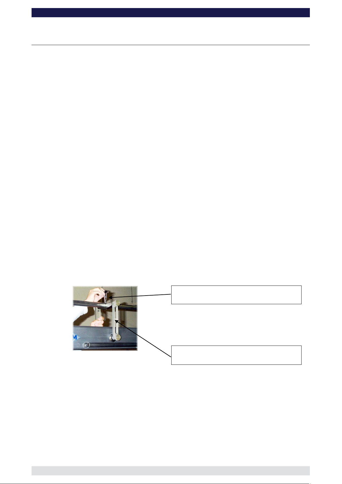
8 Xten Crane System Instruction Manual
Page: 40
GF-
Parallelogram Rod Support
The Parallelogram Rod Supports are required from Standard-Version 3 respectively
Xten-Version 2 onwards. Assembly is as follows:
The support consists of 3 parts: 2 vertical side supports and a horizontal top cradle.
Connect a side support to the top cradle by screwing the parts together. Bolt the vertical
part to the crane arm extension by turning the knurled knob. Connect the other vertical
support to opposite side by turning both knobs simultaneously.
Note: When connecting the second vertical support to the horizontal top cradle and the
crane arm, turn the top and bottom knurled knobs equally to avoid jamming.
When the parallelogram support is mounted, connect the parallelogram rod to the
horizontal top cradle by inserting the locking pin from the upper side, through the
parallelogram rod and into the horizontal top.
Positioning of the Parallelogram Rod Supports:
o Standard-Versions 3, 4, 11 and 12 on the 1st 150cm/5ft extension arm
o Standard-Versions 5, 6, 13 and 14 on the 1st & 2nd 150cm/5ft extension arm
o Standard-Versions 7, 8, 15 and 16 on the 1st & 3rd 150cm/5ft extension arm
o Standard-Versions 17 and 18 on t he 2n d & 4th 150c m /5 ft extens i o n ar m
o Xten-Versions 2 and 3 on the 2nd 150cm/5ft extension arm
o Xten-Versions 4 on the 1st & 3rd 150cm/5ft extension arm
o Xten-Versions 5 and 6 on the 1st & 4th 150cm/5ft extension arm
o Xten-Versions 7 and 8 on the 3rd & 5th 150cm/5ft extension arm
To avoid mistakes, use the crane drawings provided in the Instruction Manual etc to
ensure that all parts are in the correct position.
Horizontal Top Cradle
Parallelogram support assemb ly
Vertical Parallelogram Support
Page 42
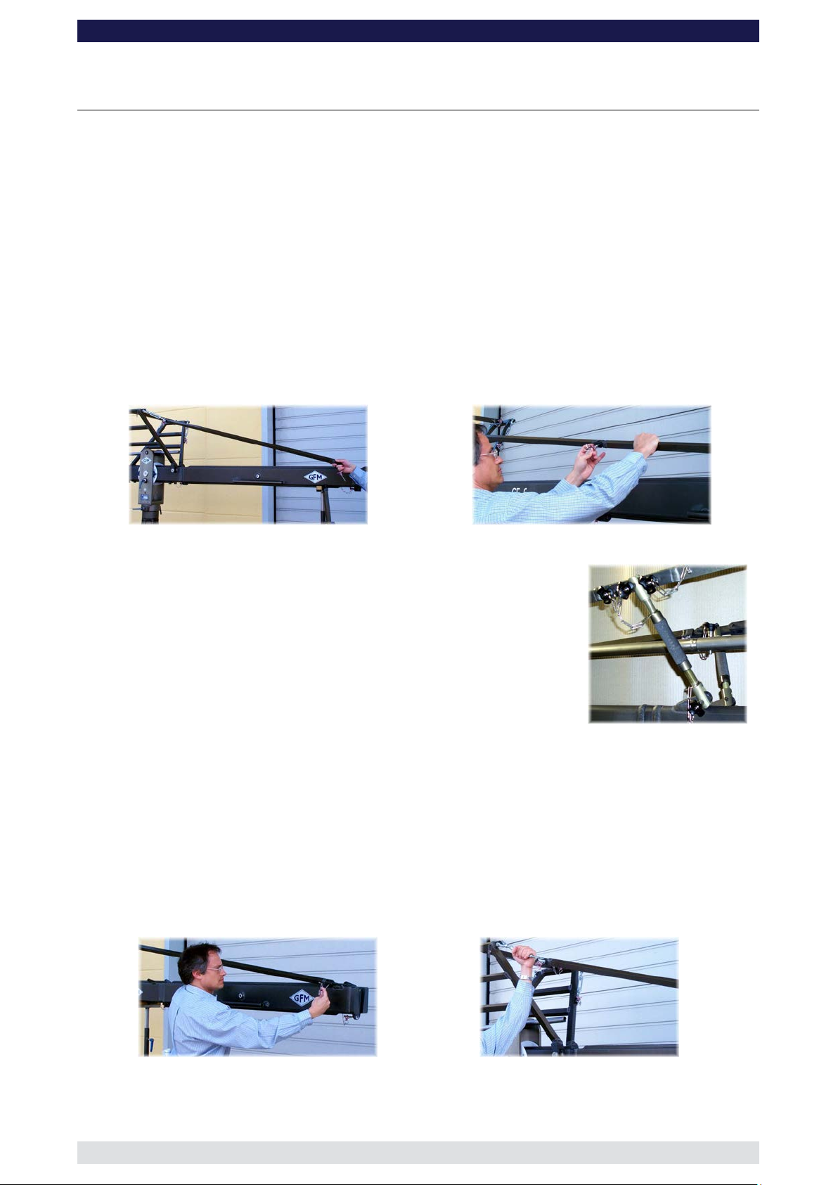
8 Xten Crane System Instruction Manual
Page: 41
Connecting 1 x 142cm rigging rod to the turnbuckle
Connecting the rods together
2. Connect another 142cm / 4’ 7” rigging rod to the first rigging
ing Rod Connector (the length of the
see the note below) to
the second rigging rod. In turn connect the Adjustable
Rigging Rod Support to the Rigging Connections on the
ng Rod
This positioning applies to versions 7, 8, 15, 16
with a locking pin.
GF-
Standard Rigging System
The rigging system must be mounted as of Standard Versions 2 onwards i.e. versions with
more than 1 x 150cm section to the front. For each extension section there is a matching
pair of rigging rods. The rods for the 150cm sections are all identical. In principle, mounting
the rigging requires connecting the respective rods starting at the turnbuckles on the
rigging harness and finishing at the connection on the last arm section or in some cases
the second last section.
100cm / 3’ 3” arm section
127cm / 4ft arm section
150cm / 5ft arm section
160cm / 5’ 3” arm section
=
72 cm / 2’ 4” rigging rod
115cm / 3’ 9” rigging rod
142cm / 4’ 7” rigging rod
142cm / 4’ 7” and 115cm / 3’ 9” rigging rod
The following example describes the assembly procedure for Versions 17 & 18
1. Connect a 142cm / 4’ 7” rigging rod to the turnbuckle on the front side of the standard
rigging harness. Ensure that the locking pin is inserted fully.
rod. Ensure that the locking pin is inserted fully.
3. Connect a Rigg
connector depends on the version –
second 150cm / 5ft arm section and then to the Riggi
Connector ensuring that the locking pins are inserted fully.
Note:
(short connector) and 17, 18 (long connector).
4. Connect 2 x 142cm / 4’ 7” rigging rods to the Rigging Rod Connector. Ensure that the
locking pins are inserted fully.
5. Connect a 115cm / 3’ 9” rigging rod to the last 142cm / 4’ 7” rigging rod and in turn to
the Rigging Rod Connection on the 127cm / 4ft arm section. Ensure that the locking
pins are inserted fully.
Attention: The Rigging Rod Connectors should be positioned in the respective
versions as per the following instructions. Furthermore the rigging
must be assembled symmetrically by using the same length rods,
connectors etc in the same position on each side.
Connect the rigging rod to the end section and secure
6. After the complete rigging system has been assembled, hand tighten the turnbuckles
until the rigging rods are taut. The turnbuckles can be secured with locking nuts.
Tensioning the turnbuckle
Page 43

8 Xten Crane System Instruction Manual
Page: 42
GF-
Make sure that the rigging is absolutely straight. For this case the Adjustable Rigging
Rod Support has to be adjusted in a proper way.
Attention: The rigging system of the crane arm should be hand tightened
symmetrically from both sides of the crane in a way that the arm is
absolutely straight when carrying the loads of the counterweight
bracket, the platform or remote bracket.
Attention: The rigging system of the following Standard Versions need to be
assembled with different length of rigging connectors. Please see the
next paragraph below!
The rigging system has also to be assembled in a symmetrical way so
that the left and the right hand side of the cranes rigging system has
the same parts at same positions.
Alignment of the rigging connectors for Standard Versions:
o Standard-Versions 17 and 18:
Long Rigging Rod Connector:
Attach to Adjustable Rigging Rod Support and use to connect 2nd and
3rd rigging rods.
Short Rigging Rod Connector:
not required.
o Standard-Versions 6 to 8 and 14 to 16:
Short Rigging Rod Connector:
For version 7, 8, 15, 16 attach to Adjustable Rigging Rod Support and
use to connect 2nd and 3rd rigging rods.
For version 6 and 14 just use to connect 2nd and 3rd rigging rods.
Long Rigging Rod Connector:
not required.
Before operation, all locking pins , loc king scr ews etc should be inspe cted to e nsure
that all assembly sections are securely fastened.
Page 44

8 Xten Crane System Instruction Manual
Page: 43
100cm / 3’ 3” arm section
160cm / 5’ 3” arm section
72 cm / 2’ 4” rigging rod
142cm / 4’ 7” and 115cm / 3’ 9” rigging rod
GF-
Double Rigging System
The Double Rigging System and Large Rigging Harness must be mounted for all
GF-8 Xten Versions. For each extension section there is a matching pair of rigging rods.
The rods for the 150cm sections are all identical. In principle, mounting the rigging requires
connecting the respective rods starting at the turnbuckles on the rigging harness and
finishing at the connection on the last arm section or in some cases the second last
section.
127cm / 4ft arm section
150cm / 5ft arm section
=
115cm / 3’ 9” rigging rod
142cm / 4’ 7” rigging rod
The following example describes the assembly procedure for the GF-8 Xten, Double
Rigging System as per Versions 7 & 8
Lower, front rigging
1. Connect a 142cm / 4’ 7” rigging rod to the lower turnbuckle on the front side of the
large rigging harness. Ensure that the locking pin is inserted fully.
2. Connect another 142cm / 4’ 7” rigging rod to the first rigging rod and in turn to the
second crane arm extension. Ensure that the locking pins are inserted fully. Hand
tighten the turnbuckles until the rigging rods are taut. The turnbuckles can be secured
with locking nuts.
Attention: After mounting the lower front rigging continue with the crane
assembly.
Connecting the rods together
Double Rigging System
Page 45

8 Xten Crane System Instruction Manual
Page: 44
Connect 3 x 142cm / 4’ 7” rigging rods to the turnbuckle
on the top front side of the large rigging harness. Ensure
Connect a long Rigging Rod Connector to the third
n turn connect the Adjustable Rigging Rod
Support to the Rigging Connection on the third 150cm /
5ft arm section and then to the Rigging Rod Connector
GF-
Top, front rigging
1.
that the locking pins are inserte d f ull y.
2.
Rigging Rod. I
ensuring that the locking pins are inserted fully.
Note: This positioning applies to versions 5 to 8.
3. Connect 2 x 142cm / 4’ 7” rigging rods to the long Rigging Rod Connector. Ensure
that the locking pins are inserte d f ull y.
4. Connect a short Rigging Rod Connector to the last 142cm / 4’ 7” rigging rod. Ensure
that the locking pin is inserted fully.
5. Connect a 115cm / 3’ 9” rigging rod to the short Rigging Rod Connector and in turn to
the Rigging Rod Connection on the 127cm / 4ft arm section. Ensure that the locking
pins are inserted fully.
Attention: The Rigging Rod Connectors should be positioned in the respective
versions as per the following instructions. Furthermore the rigging
must be assembled symmetrically by using the same length rods,
connectors etc in the same position on each side.
Short Rigging Rod Connector
6. After the complete rigging system has been assembled, hand tighten the turnbuckles
until the rigging rods are taut. The turnbuckles can be secured with locking nuts.
Make sure that the rigging is absolutely straight. For this case the Adjustable Rigging
Rod Support has to be adjusted in a proper way.
Attention: The rigging system of the crane arm should be hand tightened
symmetrically from both sides of the crane in a way that the arm is
absolutely straight when carrying the loads of the counterweight
bracket, the platform or remote bracket.
Page 46

8 Xten Crane System Instruction Manual
Page: 45
GF-
Attention: The rigging system of the following Standard Versions need to be
assembled with different length of rigging connectors. Please see the
next paragraph below!
The rigging system has also to be assembled in a symmetrical way so
that the left and the right hand side of the cranes rigging systems has
the same parts at same positions.
Alignment of the rigging connectors for Standard Versions:
o Xten-Versions 7 and 8:
Long Rigging Rod Connector:
Attach to Adjustable Rigging Rod Support and use to connect 3rd and
4th upper rigging rods.
Short Rigging Rod Connector:
Use to connect 5th and 6th upper rigging rods.
o Xten-Versions 5 and 6:
Long Rigging Rod Connector:
Attach to Adjustable Rigging Rod Support and use to connect 3rd and
4th upper rigging rods.
Short Rigging Rod Connector:
not required.
o Xten-Versions 4:
Short Rigging Rod Connector:
Use to connect 2nd and 3rd upper rigging rods.
Long Rigging Rod Connector:
not required.
o Xten-Versions 3:
Short Rigging Rod Connector:
Attach to Adjustable Rigging Rod Support and use to connect 2nd and
3rd upper rigging rods.
Long Rigging Rod Connector:
not required.
Before operation, all locking pins , loc king scr ews etc should be inspe cted to e nsure
that all assembly sections are securely fastened.
Page 47

8 Xten Crane System Instruction Manual
Page: 46
GF-
Mounting the Extra, Mini Counterweight Bucket for Xten Versions
Position the weight bucket above the Angle Adjuster so that the lower locking pin holes are
aligned and so that the connecting lip is positioned over the main weight bucket. Then
insert the locking pins on each side of the bucket.
Insert the third locking pin through the connecting lip and into the main counterweight
bucket. Ensure that the locking pins are inserted fully.
Lower locking pin holes and
locking pins found on each side
Connecting lip and locking pin
Balancing the crane arm
Attention: Before loading any weights level the weight bucket and the
platform respective remote bracket. For this case the angle
adjuster has an integrated leveller. By turning it, the
vertical plate on the angle adjuster can be set to a perfect
right angle.
When loading the crane the maximum working load
capacities and payloads must never be exceeded.
As a rule, no more than 504kg / 1108lbs of counterweight
may be used in the main counterweight bucket and no
more than 98kg / 215lbs in the Xten mini counterweight
bucket.
After the assembly procedure has been completed the seat arms, seats, risers, camera etc
may now be assembled on the platform or the remote head system may be mounted. The
working payload capacities may not be exceeded. An itemized weight list for GFM
accessories may be found below. Place the correct amount of counterweight in the weight
bucket to balance the load. Depending on the version that has been set-up, the camera
operator / operators can then take their position on the platform.
Page 48

8 Xten Crane System Instruction Manual
Page: 47
Qty.
Description
Weight kg
Weight lbs
1
Seat arm combined 10cm / 4"
AL-2210
0,75 kg
1,65 lbs
1
Seat arm combined 20cm / 8"
AL-2220
1,15 kg
2,53 lbs
1
Seat arm combined 30cm / 12"
AL-2230
1,60 kg
3,52 lbs
1
Seat arm vertical 10cm / 4"
AL-2211
1,25 kg
2,75 lbs
1
Seat arm vertical 20cm / 8"
AL-2212
1,75 kg
3,85 lbs
1
Seat arm vertical 30cm / 12"
AL-2213
2,20 kg
4,84 lbs
1
Connection pin
AL-2240
0,40 kg
0,88 lbs
1
Crane seat with seat belt
AL-1030
7,20 kg
15,84 lbs
1
Riser 10 cm / 4"
AL-2310
2,80 kg
6,16 lbs
1
Riser 20cm / 8"
AL-2320
2,95 kg
6,49 lbs
1
Riser 30cm / 12"
AL-2330
3,40 kg
7,48 lbs
1
Riser 40cm / 16"
AL-2340
3,80 kg
8,36 lbs
1
Riser 50cm / 20"
AL-2350
4,25 kg
9,35 lbs
1
Ball Adapter
AL-2150
2,17 kg
4,77 lbs
Accessories for GF-8 Crane platform weight list
Attention: The safety belts provided must be fastened upon sitting
down and kept fastened at all times when on the platform.
Only original GFM seats, seat arms, risers etc may be used.
GF-
Working load capacity = Camera operator / operators +
camera + accessories
We recommend that the camera and remote head are
additionally secured to the remote head mount with a
safety cord.
Place the required amount of counterweights in the weight bucket so that the crane arm
becomes balanced and remains in the horizontal position. If necessary, the crane can be
fine balanced by adjusting the sliding weight on the rear parallelogram at the weight
bucket. Do not forget to lock the sliding weight in position before tilting the arm.
The counterweight bucket door must be locked when operating the crane.
Unloading
Attention: The counterweights must always be gradually removed
from the counterweight bucket before personnel leave the
platform.
When the weights are removed, the platform personnel
should dismount one at a time. Extreme caution must be
given to the shifting payload at all times. When dismantling
the crane it is essential that the whole platform is
supported fully by a stable unde rlay i.e. rostrum or ground
surface. In any case the platform should not be in the air
without support.
Page 49

8 Xten Crane System Instruction Manual
Page: 48
GF-
General Safety
Attention: Before operation, all locking pins, locking screws etc
should be inspected to ensure that all assembly sections
are securely fastened.
Attention: All necessary precautions should be taken so that
unauthorized third parties cannot use or operate the c rane
and also to ensure that only authorized personnel have
access to it.
The complete lift and panning range of the GF-8 Crane
must be kept clear of obstructions at all times. A safety
clearance of 1m / 3' 3" must be observed on all sides of the
crane during operation.
Taking the crane out of service
The crane should be dismantled in the reverse order to the assembly procedure.
Operational conditions:
At a wind speed of 40km/h / 25mph crane operation must be stopped and the crane
secured, dismounted and the necessary safety precautions taken.
If it for example takes 2 mins. to unload the counterweights and take the necessary
precautions to secure the crane, one must commence with the procedure at a wind speed
of 27km/h / 16.8mph. DIN15019, part 1, section 6.1.3.
The crane may not be used in a lightening storm as there is the danger of electrocution. To
protect yourself against lightning we recommend to adjourn into a car.
Page 50

8 Xten Crane System Instruction Manual
Page: 49
Levelling leg
Monitor carrier
Accessories for GF- 8 crane
GF-
Push bar
Track wheel with brake
Mounting the accessories
Levelling Legs:
Crank the spindle up to give enough clearance to connect the levelling arm to the dovetail
connection on the base dolly. To do so, pull back the locking pin which is arranged on the
levelling leg adapter of the base dolly and slip the connection flanges into each other.
Ensure that the automatic locking pin inserts fully. When all 4 Levelling Legs are mounted
the base can be levelled.
Monitor Carrier:
Insert the monitor carrier axle through the respective holes on the pivot section and secure
with the knurled locking knobs.
Push Bar:
Can be connected to either end on the base dolly by inserting the push bar stubs into the
respective holes on the base. Lock tightly with the locking knobs.
Track Wheels:
Connect to the track wheel units to the bolts on the underside of the base. Ensure that the
automatic locking pin inserts fully. Mount the track wheels so that the track wheel brake on
each of the units as well as the automatic locking pin points towards the mounting column.
Page 51

8 Xten Crane System Instruction Manual
Page: 50
GF-
Notice:
When operating the crane with the push bar mounted on the dolly, pay attention that the
crane arm at no time collides with the push bar.
Always use the levelling legs to level the crane when on uneven surfaces.
Attention: For safety reasons only original accessories
manufactured by GFM may be used with the crane.
Use with GFM Track (GF-Track)
The maximum payload on standard GF-Track: m
o authorized GFM Cranes:
GF-9, GF-6, GF-8 Standard and GF-8 Xten with 4 x 2 (double) GF-Track Wheels.
Track width = 620mm / 24,5 inches
= 1200 kg / 2640lbs
zul
There are a number of ways to mount the GF-8 on track:
o The crane can be assembled on track
o By using the 4 levelling legs, the assembled and balanced crane can be cranked
upwards to allow the track to be placed under the base and already mounted track
wheels. The base can then be carefully lowered by cranking the 4 levelling legs
simultaneously downwards.
Attention: Increased caution while laying the tracks and lowering
the crane on tracks. Ensure that the track wheels are
parallel to the track.
o The assembled and balanced crane can be rolled onto the track by using the GFM
Starter Ramp.
Attention: To do so remove the levelling legs and ensure that the
track wheels are aligned with the track.
Moving the crane onto the track should be carried out by
at least 3 operators. It is essential to make sure that the
track underlay cannot move or shift.
Use on curved tracks:
Attention: Extreme caution if tracking on curved track (not faster
than a slow walking pace).
Page 52

8 Xten Crane System Instruction Manual
Page: 51
Transport trolle y for the GF-8 Crane
GF-
The above photos show the practical transport solution for the GF-8 Crane System. The
GFM trolley fits the complete system with dolly and column as an extra unit.
Attention: While loading and unloading parts of the crane the wheel
brakes have to be tightened.
Page 53

8 Xten Crane System Instruction Manual
Page: 52
Ideal for going through narrow doorways
and working in very confined spaces. Track
wheels are mounted by replacing the
standard rubber wheels, keeping size to a
minimum. Levelling legs are also available.
The crane platform may be mounted on the
base dolly to provide a track or western
dolly style function. Insert the 3 bolts
located on the underside of the chassis
urnstile
mount. Lock the 3 bolts tightly with an Allen
Key.
Equipped with solid rubber wheels and with
single ended, corrected steering geometry
allowing a minimum circular movement of
n roll from
floor to standard 62cm /24,5“ track by just
clicking on the track wheels. Levelling legs
and adapters to 100cm / 39“ track are also
available.
offers all the features of the standard base
uble ended steering. Each end
functions independently with a dedicated
steering rod for each operator. Can roll from
floor to standard 62cm /24,5“ track by just
clicking on the track wheels. Levelling legs
and adapters to 100cm / 39“ track are also
available.
GF-8 Crane Dollies
The GF-8 Mini Base
For use with Standard GF-8 versions.
GF-8 Base as Track or Western Dolly
GF-
through the platform and into the t
The GF-8 Standard Base Dolly
258cm / 9' 4" inside diameter. Ca
The GF-8 Double Ended Steering Base
but with do
Attention: The assembly or operation of the crane only with
pneumatic wheels is not allowed. The only exception
is when the levelling legs are mounted and the base
is levelled and supported by them. In general the
pneumatic wheels are only for transportation.
Page 54

8 Xten Crane System Instruction Manual
Page: 53
Safety knob
GF-
The GF-8 Double Ended Connected Steering Base
Offers all the features of the standard base but with GFM’s connected steering system.
The 3 steering functions are controlled from the rear of the dolly by simply flicking a lever.
You can roll from floor to standard 62cm /24,5“ track by just clicking on the track wheels.
Levelling legs and adapters to 100cm / 39“ track are also available. Provides the utmost in
manoeuvrability.
Three steering modes available:
o Front 2 wheel
o 4 wheel inverted
o Rear 2 wheel
To change steering mode please observe the following guidelines:
o Before switching, all wheels must be aligned.
o To position the switch lever in the required position first release the safety knob
(see the pictures below), found on the opposite side. After switching, reinsert the
safety knob (Steering position secured).
Switch lever (here in the upward position)
Dolly Double Ended Connected Steering
Page 55

8 Xten Crane System Instruction Manual
Page: 54
Front wheel steering
Switch lever (here in the downward position)
4 wheel steering
Switch lever (here in middle position)
GF-
Steering mode 1:
2 wheel front steering - rear wheels fixed - Operated from the rear of the dolly. In this
mode the front wheels are steered allowing a minimum circular movement of 258cm / 9'
4" inside diameter.
Steering mode 2:
4 wheel steering - all 4 wheels can be turned together giving a “roundy round“ steering
effect for narrow curves.
Steering mode 3:
2 wheel rear steering - front wheels fixed - In this mode the rear wheels are steered
from the rear of the dolly.
Rear wheel steering
Switch lever (here in upward position)
Page 56

8 Xten Crane System Instruction Manual
Page: 55
GF-
Maintenance
In general, maintenance should always be performed by qualified personnel in accordance
with relevant accident prevention regulations and generally accepted safety rules.
Recommended maintenance interval: 1 year
We recommend the owner / operator to a visual and functional test of the components
listed below several times a year, to make sure that the crane system is in good condition.
Before operating the crane all fasteners such as locking screws, connecting bolts, etc.
should be checked for tightness and integrity.
Furthermore any components and modules of the crane such as the base dolly, the
wheels, track wheel and levelling units, extensions and rigging parts, angle adjuster,
platform, remote bracket, counterweight bucket and especially the connecting flanges of
the crane sections have to be inspected for any kind of damage.
It is also necessary to check the pr oper func tion of the closure of the counterweight
bucket, the wheel brakes, the friction at the middle section and if the bearings of the
wheels of the dolly, the track wheels, the middle section, the turnstile and the angle
adjuster are running smooth.
In case of any damages of the crane, the manufacturer has to be informed immediately
about the accident details and the heaviness of the damage. In accordance with the
manufacturer further action has to be clarified.
In general damaged parts have to be sent to the manufacturer for repair or replacement.
The use of the crane with damaged parts is not allowed. The manufacturer accepts no
liability for damages or injuries for incidents or accidents occurring due to the use of
damaged parts of the crane.
Attention: For safety reasons only original spare parts manufactured
by GFM may be used for the maintenance or the reparation
of the crane.
Subject to change without prior notice
Page 57

8 Xten Crane System Instruction Manual
Page: 56
GF-
Regular Inspections
According to guideline BG V C1, § 34, r epeated i nspe ctions b y a technic al expert mus t be carried out at le ast
once every year. In add ition, insp ection thro ugh a tec hnical expert , based on the sc ope of exam ination mus t
be carried out ever y 4 years. T he inspectio ns mus t be registere d in the Lo g Book that is deliver ed with e ach
crane.
Technical experts must meet the requirements of BGV C1, §34 and §36 according to the following
explanation:
A technical expert for the annual inspection is a person who, based on their training and experience has
sufficient knowledge in:
- Areas of technica l safety and machiner y as well as the State’s related pr otective regulations for the
work place.
- Rules and regulations from the respective government safety organization.
- Recognized regulations and generally recognized technical rules and accepted technical codes of
practice (e.g. DIN norm s , VDE regulat ions, tec hnica l rules of other Europe an Un ion m em bers States
or other States that comply with the Treaty on the European Economic Area)
- Work related safety standards and technical safety for machinery.
Valid as a technical expert for the inspection of technical safety and m achine facilities every 4 years is an
expert recognized by the government safety organization. In general, the authorisation of a recognized
technical expert requires the following:
a) Completed studies as an Engineer
b) A minimum of 3 years experience in construction design, assembly or maintenance of safety relevant
and technical facilities.
It is recommended that the safety inspections be carried out by GFM or a local recognized expert.
Contact details of domestic and foreign technical experts can be obtained from recognized technical
surveillance organizations (e.g. TÜV).
Page 58

8 Xten Crane System Instruction Manual
Page: 57
GF-
EC Declaration of Conformi ty
The company Gri p Factory Munich GmbH
Fürholzener Str. 1
D-85386 Eching
declares, that the crane Type: GF-8 / GF-8 Xten
Model: Cameracrane
Serial No. and year of manufacturing:
see identification plat e
complies with the machine guidelines 2006/42/EG (May 2006)
This EC Declaration of Conformity will become invalid should the crane be in any way
modified and the modifications not be authorized by us in writing.
Eching, March 2011
Antonio Tundo - director of company
Derek Magee - director of company
Armin Weileder - director of company
 Loading...