

Page 1

Grip Factory Munich
YOUR INNOVATIVE PARTNER FOR CAMERA SUPPORT
GF-16
Crane System
Instruction Manual
Grip Factory Munich GmbH
Fürholzener Straße 1
85386 Eching bei München
Germany
Valid: March 2010
Tel.: +49 (0) 89 319 0 129-0
Fax: +49 (0) 89 319 0 129-9
e-Mail: info@g-f-m.net
http://www.g-f-m.net
Page 2

GF-16 Crane System Instruction Manual
Contents:
SAFETY GUIDELINES............................................................................................... 2
Assembly Procedure – GF-16..................................................................................... 3
For all versions: ............................................................................................................3
The GF-16 Adjustable Mounting Column:................................................................... 4
Pivot Section............................................................................................................... 5
General Assembly ...................................................................................................... 5
Version 1 ......................................................................................................................7
Version 2 ......................................................................................................................8
Rigging system........................................................................................................... 9
General:........................................................................................................................9
Rigging Harness Assembly:..........................................................................................9
Parallelogram Supports ............................................................................................ 10
Version 3 ....................................................................................................................11
Version 4 ....................................................................................................................13
Version 5 ....................................................................................................................15
Version 6 ....................................................................................................................17
Version 7 ....................................................................................................................19
Version 8 ....................................................................................................................21
Version 9 ....................................................................................................................23
Version 10 ..................................................................................................................26
Version 11 ..................................................................................................................29
Version 12 ..................................................................................................................32
Version 13 ..................................................................................................................35
Version 14 ..................................................................................................................38
Version 15 ..................................................................................................................41
Remote Head Mount................................................................................................. 43
Balancing the crane arm........................................................................................... 44
Deloading: ..................................................................................................................44
General Safety............................................................................................................44
Positioning the Adjustable Mounting Column............................................................ 45
GF-16 Camera Crane and Dolly Dimensions............................................................ 46
Dolly weight................................................................................................................46
Accessories for GF-16 Crane platform weight list.......................................................47
Transport trolley for the GF-16 Crane.........................................................................48
Maintaining the Adjustable Column .......................................................................... 49
Dismantling the column:..............................................................................................49
Maintenance...............................................................................................................50
Regular Inspections....................................................................................................51
EC Declaration of Conformity ................................................................................... 52
Page: 1
Page 3

GF-16 Crane System Instruction Manual
SAFETY GUIDELINES
The set-up instructions must be read and understood before set-up or operation. The crane may only be
assembled in accordance with the manufacturer’s instruction manual. The manufacturers technical
specifications and limits (maximum rated loads of each version) must be adhered to at all times and in no
way exceeded.
The GF-16 Crane may only be set-up or operated by trained and experienced personnel. To assemble the
crane at least two men are needed. To avoid misuse by untrained personnel, the crane should be dismantled
when not in use or under supervision.
For further information on the qualifications required for test personnel please refer to BGV 1, §33 and §34.
The crane may not be set-up or operated under the influence of alcohol, drugs or any other intoxicating
substances. The respective protective clothing e.g. gloves, should be worn.
The manufacturer accepts no liability for damages or injuries for incidents or accidents occurring due to
negligence by the crane operator or misuse of the crane or disregarding the instruction manual.
Before assembling the crane ensure that the ground surface is stable and cannot give way. The ground
surface must be stable enough to support at least 2300 kg/m2 = 5060 lbs/ sq yard.
Crane operation is only allowed with solid tires. Use with pneumatic wheels is not allowed. Before and while
using the crane the wheels should be inspected.
Whether operating or moving the crane on track or on a solid ground surface it is essential that the track or
surface is completely level, stable and free from obstructions. If necessary, level the crane with the provided
levelling legs.
When operating the crane on track, ensure that the track is level, properly laid and constructed. The correct
underlay must be used to ensure that the track and underlay are secured against moving, slipping and
collapse. Ensure that the underlay provides the specified support and stability. Use the manufacturers
mounting ramp when driving on or off track.
Operation on curved track is strictly forbidden.
Use of the crane on insert vehicles, camera cars or any motorised vehicle is not allowed. The
manufacturer accepts no liability for damages or injuries for incidents or accidents occurring due to use of
the crane on insert vehicles, camera cars or any other motorised vehicles.
Changing weather conditions should be taken into consideration. The crane must be taken out of operation
before the operational wind speed reaches 25km/h (15.6mph). For this purpose see page 44.
The complete lift and panning range of the GF-16 Crane must be kept clear of obstructions at all times. A
safety clearance of 1m / 3' 3" must be observed on all sides of the crane during operation. Only authorised,
trained and experienced personnel are allowed to operate the crane. In the interest of safe crane operation,
when operating or moving the crane, abrupt, sudden movements of the crane should be avoided. An
element of risk remains by people moving in the operational range of the crane. The crane operator has to
be trained on that and is only allowed to operate the crane in safe range.
The crane may not be used in the direct vicinity of high voltage power cables. To avoid accidents due to
misuse in the vicinity of high voltage power cables, Safety Guidelines (especially VBG 1 and 4) as well as
VDE regulations (especially 0105 part 100) must be adhered to. If the nominal voltage cannot be
determined, a minimum clearance of 5m / 16ft must be kept at all times. Failing to do so can cause fatalities.
Personnel on board the crane's platform must use safety belts at all times. They should not make any
sudden, abrupt movements or lean out over the side of the platform. No loose objects may be stored or
placed on the crane platform.
Before the counterweights are removed from the bucket, ensure that the platform is resting on the ground or
alternatively supported by an appropriate stable underlay. Gradually remove the counterweights before
personnel leave the platform or before the remote head or camera are dismounted. It’s not allowed to put
extra weights on top of the counterweight bucket or any other part of the crane!
For safety reasons only original accessories manufactured by GFM may be used with the crane.
Page: 2
Page 4
GF-16 Crane System Instruction Manual
Assembly Procedure – GF-16
General description:
The GF-16 is a mobile crane-system for mounting cameras in a stationary ground position
or for movement on track.
It can be operated manually from the ground and can be panned in all directions either
with a remote-bracket or a 1 to 2 person platform. In accordance to the safety guidelines
the crane is only allowed to be used on solid, level and stable ground. While using it
stationary the levelling legs have to be used.
The crane operation from the ground is managed by at least one experienced, trained and
authorised personnel from the hand grips on the counterweight bucket.
Operation of the crane is only allowed within the limits and guidelines mentioned in the
instruction manual. The allowed payloads of each version are clearly shown on the
counterweight-bucket (workplace of the crane operator).
Attention: Before and during assembly observe the Safety Guidelines.
For all versions:
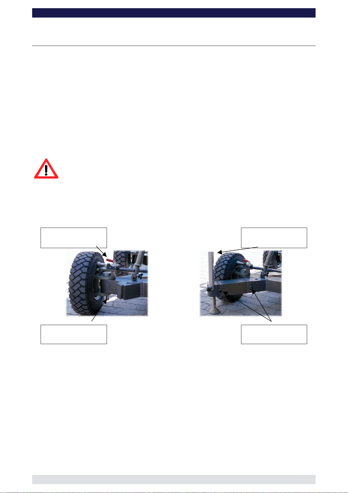
1. Secure the base dolly so that it cannot move or roll. Lock all wheel brakes. Move the
steering rod towards the centre of the dolly or remove it so that the set-up personnel
do not trip over it.
Wheel brake
Track wheel
Connection
The levelling legs should be used to level the base when stationary
Levelling leg
Locking pin
Page: 3
Page 5
GF-16 Crane System Instruction Manual
The GF-16 Adjustable Mounting Column:
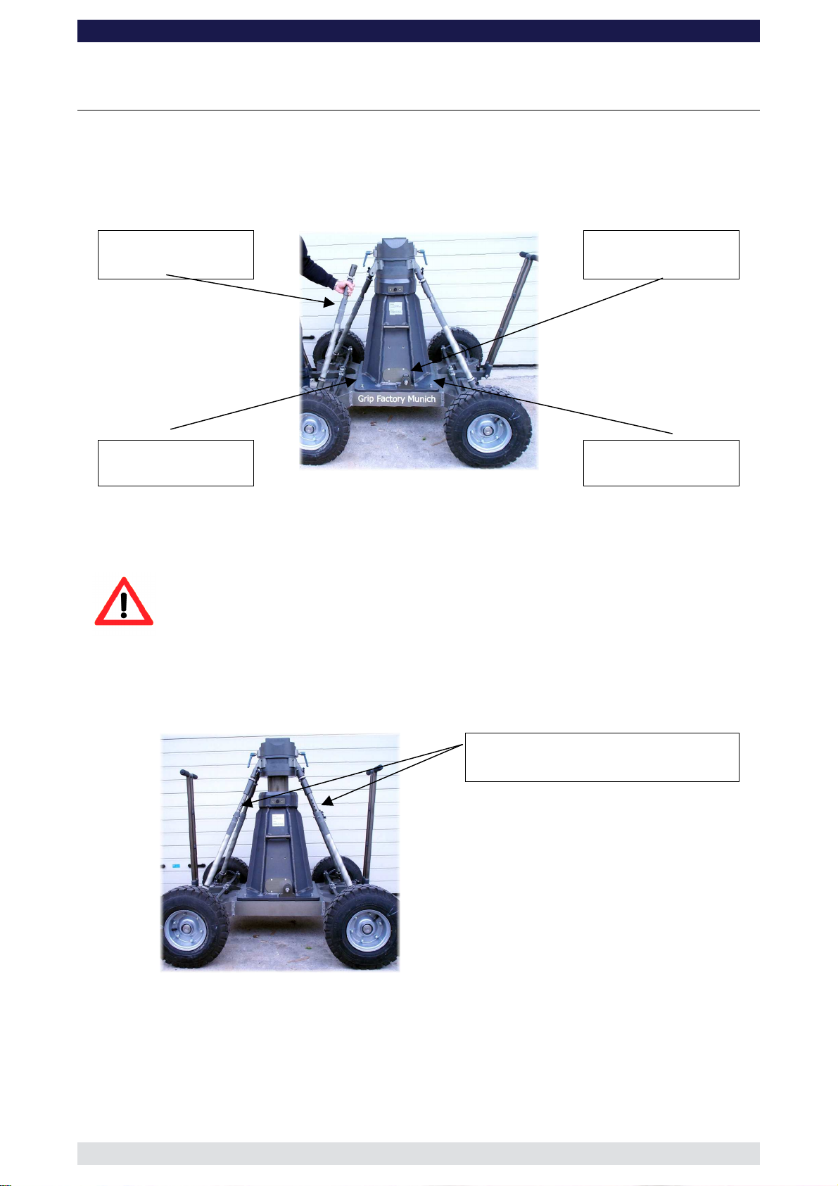
2. Bolt the Adjustable Mounting Column to the base dolly. Make sure that the locking
bolts are locked securely.
Tip: The carrying handles on the bazooka should point to the left and right of the
dolly.
Adjustable stabilizing
rods
Column drive
Connection
Locking bolts
Locking bolts
3. Connect the 4 Adjustable Stabilizing Rods between the base and the column by
securing each one with a locking pin at the top and bottom of each rod.
Important:
When adjusting the height of the column make sure that the 4
Adjustable Stabilizing Rods can move freely and that they are not
restricted in travel. The Rod Locking Pin found in the middle of each
rod must be removed when adjusting the height and reinserted only
when the column is in the required position.
Rod Locking Pins
Page: 4
Page 6
GF-16 Crane System Instruction Manual
Pivot Section
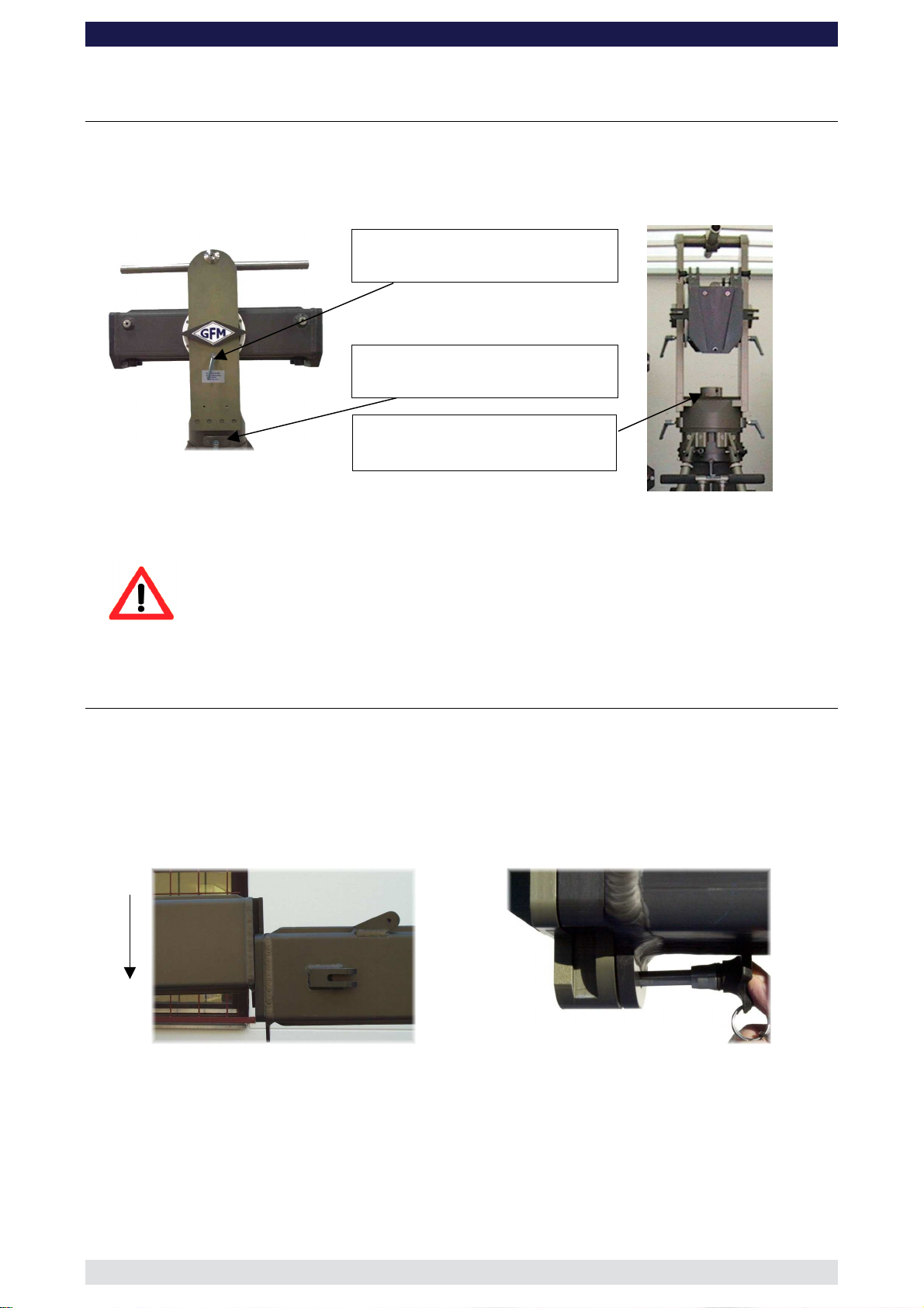
4. Located on the middle section are 2 tilt friction locks which may be used to lock the tilt
during set-up. Set the pivot arm at 90° to the cent re post and lock the friction locks
which can be found on the left and right hand side of the middle section.
Tilt friction
Pan friction
Middle section
Locking screw
5. Mount the middle section on the mounting column. Lock the locking screw tightly.
Tip: A 12mm Allen key can be found in the mounting column’s handle to be used
as a lever.
Attention: Install the middle section to the rotate able bearing of the
column with positive locking. It fits properly only in one
position.
General Assembly
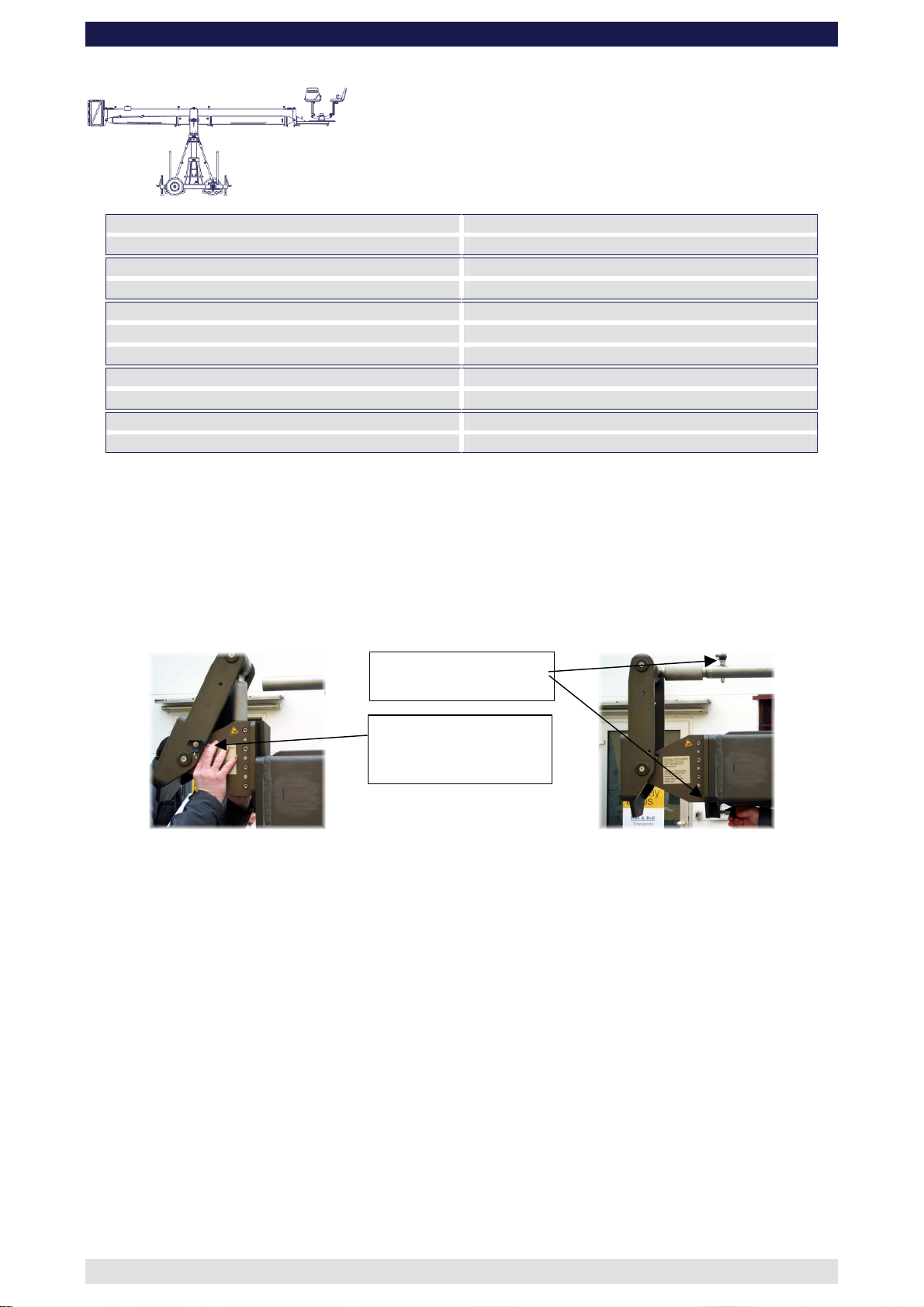
6. Connect extension number 1 to the middle section. Slip the connection flanges into
each other and secure with the provided safety pin.
Tip: To avoid the sections jamming or getting stuck make sure that the sections
are joined parallel. Using a small amount of lubricant also helps. We suggest
rubbing the joints with an oiled rag prior to assembly.
Mounting an extension arm
Securing the arm with a safety pin
7. Connect the 192cm / 6’3” counterweight bucket extension to the middle section. Slip
the connection flanges into each other and secure with the provided safety pin.
8. Connect the 192cm / 6’3” parallelogram rod to the parallelogram connection on the
middle section and secure it with the provided safety pin.
9. Release the angle adjuster located at the end of the 192cm / 6’3” section by removing
the safety pin from the side of the angle adjuster.
Page: 5
Page 7
GF-16 Crane System Instruction Manual
Attention: Pinch point
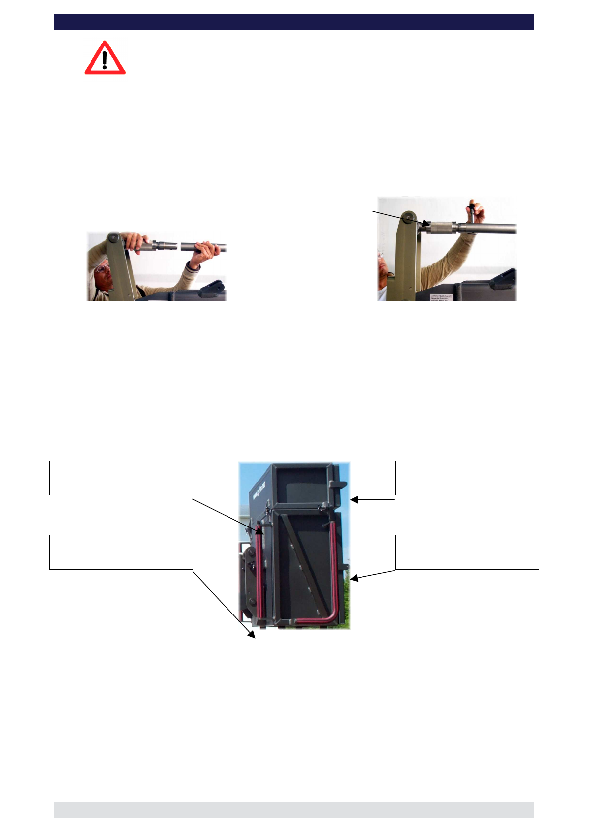
Tip: With the removed safety pin the connection between counterweight bucket
and angle adjuster has to be secured.
10. Connect the parallelogram rod to the rod on the angle adjuster and secure it with the
provided pin.
Tip: The angle adjuster has an integrated leveller. By turning it, the vertical plate
on the angle adjuster can be set to a perfect right angle. Correct setting of
the angle adjuster enhances the crane’s balance.
Leveller
11. Support the mounted counterweight section with a suitable support stand or rostrum.
12. Connect the lower section of the 2 part counterweight bucket to the angle adjuster
located on the rear of the counterweight bucket extension. Slip the connection flanges
into each other and secure with the removed safety pin from the side of the angle
adjuster.
Tip: Do not load weights until the rigging system is mounted (see page 9).
Tip: To mount the top bucket just put it on top of the lower one and screw it either
with the provided safety pins or the captive screws. (See the GF-16
Specifications at which version the Top Bucket is needed)
Bucket connection pins
Safety pin
Top bucket
Lower bucket
The assembly procedure up to this point is the same in all versions.
To assist the set-up procedure and to reduce the risk of accidents it is
recommended to use set-up support stands or rostrums to support the crane arm
during set-up and breakdown.
Page: 6
Page 8
Angle adjuster locked
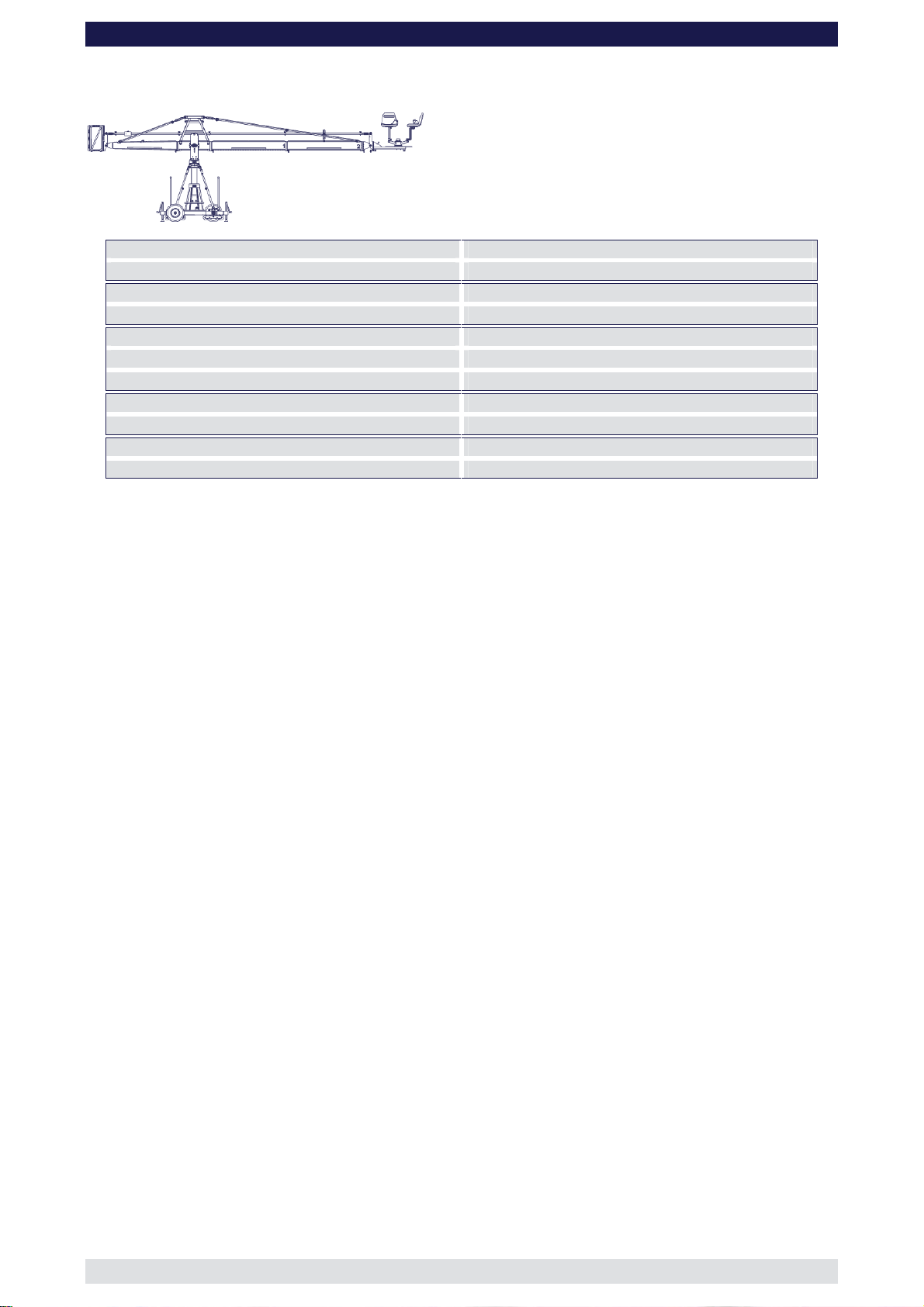
Version 1
GF-16 Crane System Instruction Manual
Front extension arms required 1 x 200 cm / 6' 6”
Rear extension arm required 1 x 192 cm / 6' 3”
Lift range 420 cm / 13’ 9”
Maximum Euro-adapter height 423 cm / 13’ 10”'
Lift capacity (working load) 2 pers. + accessories 250 kg / 550 lbs
Counterweight required for max. load 274 kg / 602 lbs
Counterweight required to balance empty arm 8 kg / 17 lbs
Crane weight (excluding dolly and weights) 661 kg / 1457 lbs
Dolly weight (unit weights see page 46) 244 kg / 536 lbs
Arm reach (pivot to camera head mount) 336 cm / 11’
Length of rear end (pivot to outside of bucket) 278 cm / 9’ 1”
Continue from § 12, page 6
13. Connect the angle adjuster to the end of the 200cm / 6’ 6” extension number 1.
Release the angle adjuster by removing the safety pins from the side of the angle
adjuster. Secure the angle adjuster to extension number 1 with a removed safety pin.
Tip: The angle adjuster has two sidewise safety pins. These are either used for
the angle adjusters transport position or to secure the connections between
angle adjuster and extension as well as angle adjuster and platform.
Safety pin
by pin (Transport
position)
Mounting the angle adjuster
Securing the angle adjuster
14. Connect one of the 200cm / 6’ 6” parallelogram rods to the rod connection located on
the middle section and secure it the provided safety pin.
15. Connect the parallelogram rod to the rod connection on the angle adjuster and secure
it with the provided safety pin.
Tip: The angle adjuster has an integrated leveller. By turning it, the vertical plate
on the angle adjuster can be set to a perfect right angle. Correct setting of
the angle adjuster enhances the crane’s balance.
16. Connect the platform to the angle adjuster and secure with the removed safety pin
from the side of the angle adjuster. Ensure that the platform is level.
17. Remove the support stand or rostrum supporting the counterweight bucket section.
18. Then unlock the tilt friction.
Before operation, all locking pins, locking screws etc should be inspected to ensure
that all assembly sections are securely fastened.
Read “Balancing the crane arm” on page 44.
Page: 7
Page 9
Version 2
GF-16 Crane System Instruction Manual
Front extension arms required 1 x 200 cm / 6' 6” + 1 x 100 cm / 3’ 3”
Rear extension arm required 1 x 192 cm / 6' 3”
Lift range 575 cm / 18’ 10”
Maximum Euro-adapter height 501 cm / 16' 5 "
Lift capacity (working load) 2 pers. + accessories 250 kg / 550 lbs
Counterweight required for max. load 424 kg / 932 lbs
Counterweight required to balance empty arm 36 kg / 79 lbs
Crane weight (excluding dolly and weights) 678 kg / 1495 lbs
Dolly weight (unit weights see page 46) 244 kg / 536 lbs
Arm reach (pivot to camera head mount) 434 cm / 14’ 2”
Length of rear end (pivot to outside of bucket) 278 cm / 9’ 1”
Continue from § 12, page 6
13. Connect the 100cm / 3’ 3” extension to extension number 1. Slip the connection
flanges into each other and secure with the provided safety pin.
Note: The 100cm / 3’ 3” section must be supported by a suitable support stand or
rostrum.
Tip: To avoid the sections jamming or getting stuck make sure that the sections
are joined parallel. Using a small amount of lubricant also helps. We suggest
rubbing the joints with an oiled rag prior to assembly.
14. Connect a 200cm / 6’ 6” parallelogram rod to the parallelogram connection on the
middle section and secure it with the provided safety pin.
15. Connect the 100cm / 3’ 3” parallelogram rod to the first parallelogram connection and
secure it with the provided safety pin.
16. Connect the angle adjuster to the end of the 100cm / 3’ 3” extension. Release the
angle adjuster by removing the safety pins from the side of the angle adjuster. Secure
the angle adjuster to the 100cm / 3’ 3” extension with a removed safety pin.
Tip: The angle adjuster has two sidewise safety pins. These are either used for
the angle adjusters transport position or to secure the connections between
angle adjuster and extension as well as angle adjuster and platform.
17. Connect the 100cm / 3’ 3” parallelogram rod to the rod on the angle adjuster and
secure it with the provided safety pin.
Tip: The angle adjuster has an integrated leveller. By turning it, the vertical plate
on the angle adjuster can be set to a perfect right angle. Correct setting of
the angle adjuster enhances the crane’s balance.
18. Connect the platform to the angle adjuster and secure with the removed safety pin
from the side of the angle adjuster. Ensure that the platform is level.
19. Remove the support stand or rostrum supporting the counterweight bucket section.
20. Then unlock the tilt friction.
Before operation, all locking pins, locking screws etc should be inspected to ensure
that all assembly sections are securely fastened.
Read “Balancing the crane arm” on page 44.
Page: 8
Page 10
GF-16 Crane System Instruction Manual
Rigging system
The rigging system must be used from Version 3 upwards.
General:
For versions using more than 3 x 200cm long sections (versions 7 to 15), a double
rigging system must be mounted. During assembly, to support the arm and ensure that it
does not dip, mount the lower rigging system as soon as crane arm sections 2, 3 or 4
(depending on version) are mounted. When the lower rigging is mounted and adjusted,
only then add on section 4, 5 and 6 etc. As soon as the last section is mounted, then
assemble the top rigging system.
Tip: Do not load weights until the rigging system is mounted.
Never use the crane with 2 or more than 2 x 200cm sections mounted without rigging.
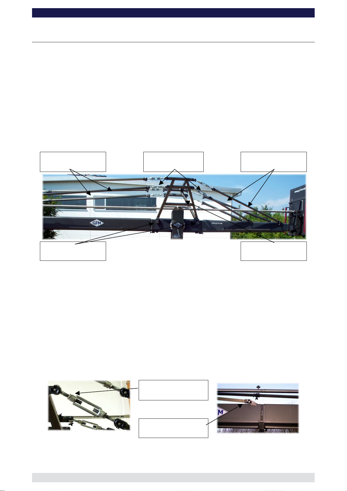
Standard Rigging rods
Turnbuckles
Rear Rigging rods
Locking bolts
Rigging harness
Rigging Harness Assembly:
1. Connect the rigging harness to both sides of the middle section and connect with the
2 cross bars. Then ensure that the 4 locking bolts are inserted and tightened fully to
the Pivot Section. Ensure that the 4 locking pins securing the 2 cross bars are
inserted fully.
2. Connect the turnbuckles to the rear rigging harness and in turn connect the 4 rear
rigging rods to the 4 rigging connections on the counterweight bucket arm. Connect
the 2 x 90cm rods to the lower turnbuckles and in turn to the inner connections on the
rear section. Then connect the 2 x 150cm rods to the top turnbuckles and in turn to
the outer connections on the rear section. Ensure that the locking pins are inserted
fully. Hand tighten the rods by turning the turnbuckles until the 4 rods are taut, then
secure the turnbuckles with the locking nut.
Locking nut
Rigging connector
Note: All rigging support brackets are identical, all rigging rod connectors are
identical, all standard rigging rods are identical.
Page: 9
Page 11
GF-16 Crane System Instruction Manual
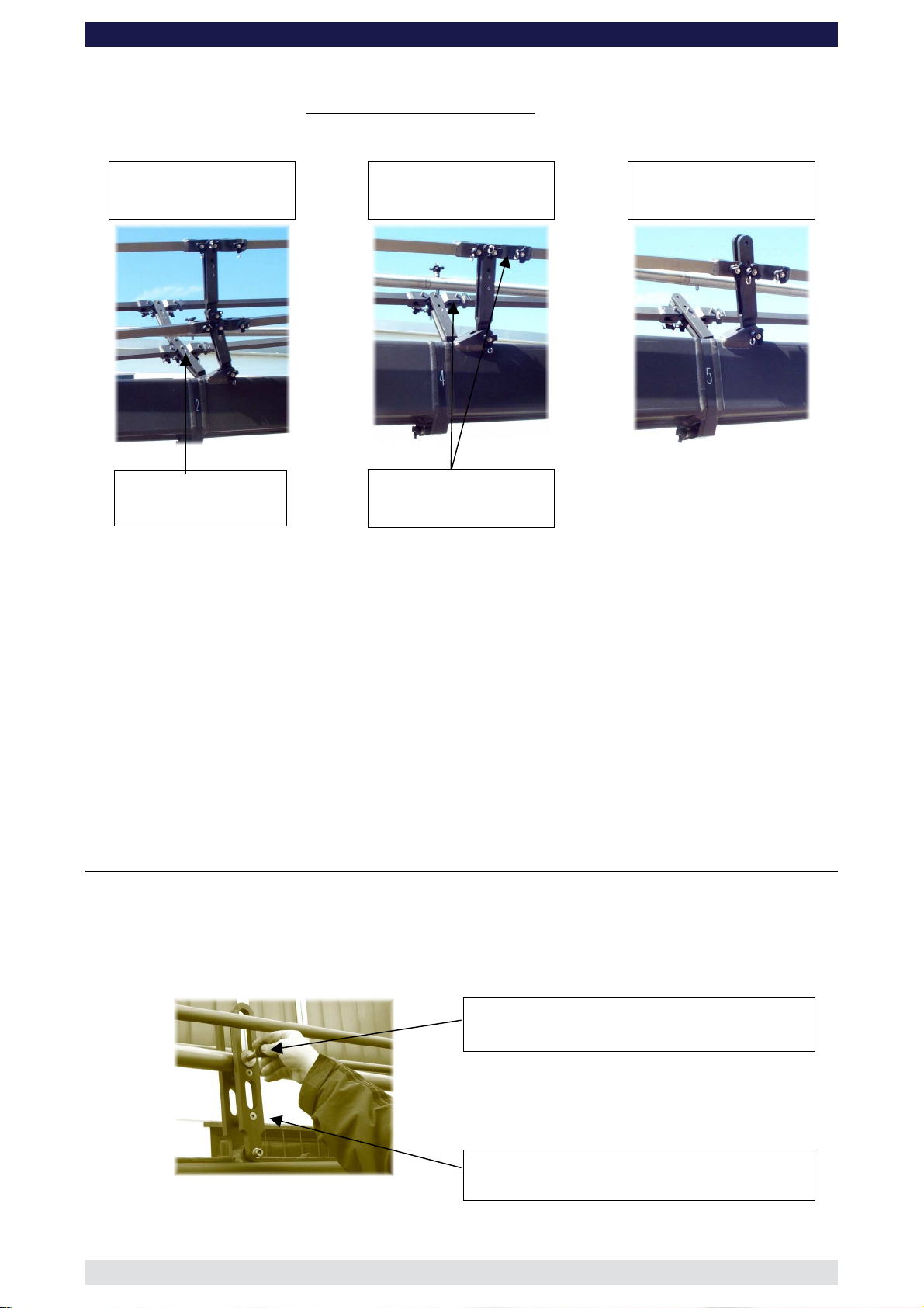
In general, the length of the rigging system depends on the number of extension arms
assembled. For each extension arm, 1 rigging rod length consisting of 2 rods, is required.
From Version 7 upwards, i.e. more than 3 extensions a double rigging system is required
i.e. top and bottom.
Top and lower rigging
support brackets, section
2
Rigging support bracket,
section 4
Rigging support bracket,
section 5
Rigging support
bracket
Rigging rod connector
The top rigging system is assembled in the same manner as the lower but starts off at the
top connection on the harness and finishes at the last extension.
The rigging system should be supported in certain positions with the Rigging Support
Brackets which connect to various sections. The Rigging Support Brackets are connected
to the Rigging Rod Connectors. Please refer to the individual versions as described on
pages 7 to 43.
It is important that the rigging system when taut, should run in a straight line and the crane
extensions should not bend or dip.
The second, fourth and fifth rigging rods are connected to the following rods via a
rigging rod connector.
Parallelogram Supports
By adding extension sections in numerical order plus the respective parallelogram rods, 15
standard versions can be built. When sections number 2, 4 and 6 as well as the Remote
section are used, support the respective parallelogram rods with the integrated
parallelogram supports.
Safety pin
Parallelogram support assembly
Parallelogram support
Page: 10
Page 12
GF-16 Crane System Instruction Manual
Version 3
Front extension arms required 2 x 200 cm / 6' 6”
Rear extension arm required 1 x 192 cm / 6' 3”
Lift range 734 cm / 24’
Maximum Euro-adapter height 581 cm / 19’
Lift capacity (working load) 2 pers. + accessories 250 kg / 550 lbs
Counterweight required for max. load 554 kg / 1218 lbs
Counterweight required to balance empty arm 56 kg / 123 lbs
Crane weight (excluding dolly and weights) 730 kg / 1609 lbs
Dolly weight (unit weights see page 46) 244 kg / 536 lbs
Arm reach (pivot to camera head mount) 534 cm / 17’ 6”
Length of rear end (pivot to outside of bucket) 278 cm / 9’ 1”
Continue from § 12, page 6
13. Connect the 200cm / 6’ 6” extension number 2 to extension number 1. Slip the
connection flanges into each other and secure with the provided safety pin.
Note: Section 2 must be supported by a suitable support stand or rostrum.
Tip: To avoid the sections jamming or getting stuck make sure that the sections
are joined parallel. Using a small amount of lubricant also helps. We suggest
rubbing the joints with an oiled rag prior to assembly.
14. Connect a 200cm / 6’ 6” parallelogram rod to the parallelogram connection on the
middle section and secure it with the provided safety pin.
15. Connect another 200cm / 6’ 6” parallelogram rod to the first parallelogram connection
and secure it with the provided safety pin.
Note: Support the second parallelogram rod with the parallelogram support on
section 2 and secure with the locking pin as shown on page 10.
16. Connect the angle adjuster to of the 200cm / 6’ 6” extension number 2. Release the
angle adjuster by removing the safety pins from the side of the angle adjuster. Secure
the angle adjuster to extension number 2 with a removed safety pin.
Tip: The angle adjuster has two sidewise safety pins. These are either used for
the angle adjusters transport position or to secure the connections between
angle adjuster and extension as well as angle adjuster and platform.
17. Connect the last 200cm / 6’ 6” parallelogram rod to the rod on the angle adjuster and
secure it with the provided safety pin.
Tip: The angle adjuster has an integrated leveller. By turning it, the vertical plate
on the angle adjuster can be set to a perfect right angle. Correct setting of
the angle adjuster enhances the crane’s balance.
The “Rigging Harness Assembly” is described on page 9. After reading and
following the instructions, please proceed as follows.
18. Connect 2 turnbuckles to the top connection on the front side of the rigging harness.
Ensure that the locking pins are inserted fully.
19. Connect 2 standard rigging rods to the turnbuckles on the front side of the rigging
harness. Ensure that the locking pins are inserted fully.
Page: 11
Page 13

GF-16 Crane System Instruction Manual
20. Connect another 2 standard rigging rods to the first 2 standard rigging rods. Ensure
that the locking pins are inserted fully.
21. Connect the last 2 standard rigging rods to the 2 rigging rod connectors on arm
extension number 2. Ensure that the locking pins are inserted fully.
22. Hand tighten the rods by turning the turnbuckles until the rods are taut, then secure
the turnbuckles with the locking nut as seen on page 9.
Attention: The rigging system when taut as well as the crane arm, should run in a
straight line and should not bend or dip.
23. Connect the platform to the angle adjuster and secure with the removed safety pin
from the side of the angle adjuster. Ensure that the platform is level.
Tip: The angle adjuster has an integrated leveller. By turning it, the vertical plate
on the angle adjuster can be set to a perfect right angle. Correct setting of
the angle adjuster enhances the crane’s balance.
24. Remove the support stand or rostrum supporting the counterweight bucket section.
25. Then unlock the tilt friction.
Before operation, all locking pins, locking screws etc should be inspected to ensure
that all assembly sections are securely fastened.
Read “Balancing the crane arm” on page 44.
Page: 12
Page 14

GF-16 Crane System Instruction Manual
Version 4
Front extension arms required 2 x 200 cm / 6' 6” + 1 x 100 cm / 3’ 3”
Rear extension arm required 1 x 192 cm / 6' 3”
Lift range 890 cm / 29’ 2”
Maximum Euro-adapter height 658 cm / 21' 7”
Lift capacity (working load) 2 pers. + accessories 250 kg / 550 lbs
Counterweight required for max. load 718 kg / 1579 lbs
Counterweight required to balance empty arm 112 kg / 246 lbs
Crane weight (excluding dolly and weights) 750 kg / 1653 lbs
Dolly weight (unit weights see page 46) 244 kg / 536 lbs
Arm reach (pivot to camera head mount) 631 cm / 20’ 8”
Length of rear end (pivot to outside of bucket) 278 cm / 9’ 1”
Continue from § 12, page 6
13. Connect the 200cm / 6’ 6” extension number 2 to extension number 1. Slip the
connection flanges into each other and secure with the provided safety pin.
Note: Section 2 must be supported by a suitable support stand or rostrum.
Tip: To avoid the sections jamming or getting stuck make sure that the sections
are joined parallel. Using a small amount of lubricant also helps. We suggest
rubbing the joints with an oiled rag prior to assembly.
14. Connect the 100cm / 3’ 3” extension to extension number 2. Slip the connection
flanges into each other and secure with the provided safety pin.
15. Connect a 200cm / 6’ 6” parallelogram rod to the parallelogram connection on the
middle section and secure it with the provided safety pin.
16. Connect another 200cm / 6’ 6” parallelogram rod to the first parallelogram connection
and secure it with the provided safety pin.
Note: Support the second parallelogram rod with the parallelogram support on
section 2 and secure with the locking pin as shown on page 10.
17. Connect the 100cm / 3’ 3” parallelogram rod to the last parallelogram connection and
secure it with the provided safety pin.
18. Connect the angle adjuster to the end of the 100cm / 3’ 3” extension. Release the
angle adjuster by removing the safety pins from the side of the angle adjuster. Secure
the angle adjuster to the 100cm / 3’ 3” extension with a removed safety pin.
Tip: The angle adjuster has two sidewise safety pins. These are either used for
the angle adjusters transport position or to secure the connections between
angle adjuster and extension as well as angle adjuster and platform.
19. Connect the 100cm / 3’ 3” parallelogram rod to the rod on the angle adjuster and
secure it with the provided safety pin.
Tip: The angle adjuster has an integrated leveller. By turning it, the vertical plate
on the angle adjuster can be set to a perfect right angle. Correct setting of
the angle adjuster enhances the crane’s balance.
The “Rigging Harness Assembly” is described on page 9. After reading and
following the instructions, please proceed as follows.
20. Connect 2 turnbuckles to the top connection on the front side of the rigging harness.
Ensure that the locking pins are inserted fully.
Page: 13
Page 15

GF-16 Crane System Instruction Manual
21. Connect 2 standard rigging rods to the turnbuckles on the front side of the rigging
harness. Ensure that the locking pins are inserted fully.
22. Connect another 2 standard rigging rods to the first 2 standard rigging rods. Ensure
that the locking pins are inserted fully.
23. Connect 2 rigging rods in turn to the connectors on extension number 2. Ensure that
the locking pins are inserted fully.
24. Hand tighten the rods by turning the turnbuckles until the rods are taut, then secure
the turnbuckles with the locking nut as seen on page 9.
Attention: The rigging system when taut as well as the crane arm, should run in a
straight line and should not bend or dip.
25. Connect the platform to the angle adjuster and secure with the removed safety pin
from the side of the angle adjuster. Ensure that the platform is level.
Tip: The angle adjuster has an integrated leveller. By turning it, the vertical plate
on the angle adjuster can be set to a perfect right angle. Correct setting of
the angle adjuster enhances the crane’s balance.
26. Remove the support stand or rostrum supporting the counterweight bucket section.
27. Then unlock the tilt friction.
Before operation, all locking pins, locking screws etc should be inspected to ensure
that all assembly sections are securely fastened.
Read “Balancing the crane arm” on page 44.
Page: 14
Page 16

GF-16 Crane System Instruction Manual
Version 5
Front extension arms required 3 x 200 cm / 6' 6”
Rear extension arm required 1 x 192 cm / 6' 3”
Lift range 1049 cm / 34’ 4”
Maximum Euro-adapter height 738 cm / 24' 2”
Lift capacity (working load) 2 pers. + accessories 250 kg / 550 lbs
Counterweight required for max. load 896 kg / 1971 lbs
Counterweight required to balance empty arm 182 kg / 400 lbs
Crane weight (excluding dolly and weights) 769 kg / 1695 lbs
Dolly weight (unit weights see page 46) 244 kg / 536 lbs
Arm reach (pivot to camera head mount) 731 cm / 23’ 11”
Length of rear end (pivot to outside of bucket) 278 cm / 9’ 1”
Continue from § 12, page 6.
13. Connect the 200cm / 6’ 6” extension number 2 to extension number 1. Slip the
connection flanges into each other and secure with the provided safety pin.
Note: Section 2 must be supported by a suitable support stand or rostrum.
Tip: To avoid the sections jamming or getting stuck make sure that the sections
are joined parallel. Using a small amount of lubricant also helps. We suggest
rubbing the joints with an oiled rag prior to assembly.
14. Connect the 200cm / 6’ 6” extension number 3 to extension number 2. Slip the
connection flanges into each other and secure with the provided safety pin.
Note: Move the support stand or rostrum to support section number 3.
15. Connect a 200cm / 6’ 6” parallelogram rod to the parallelogram connection on the
middle section and secure it with the provided safety pin.
16. In turn, connect 2 x 200cm / 6’ 6” parallelogram rods to the first parallelogram
connection and secure them with the provided safety pins.
17. Connect the angle adjuster to the end of the 200cm / 6’ 6” extension number 3.
Release the angle adjuster by removing the safety pins from the side of the angle
adjuster. Secure the angle adjuster to extension number 3 with a removed safety pin.
Tip: The angle adjuster has two sidewise safety pins. These are either used for
the angle adjusters transport position or to secure the connections between
angle adjuster and extension as well as angle adjuster and platform.
18. Connect the last 200cm / 6’ 6” parallelogram rod to the rod on the angle adjuster and
secure it with the provided safety pin.
Tip: The angle adjuster has an integrated leveller. By turning it, the vertical plate
on the angle adjuster can be set to a perfect right angle. Correct setting of
the angle adjuster enhances the crane’s balance.
The “Rigging Harness Assembly” is described on page 9. After reading and
following the instructions, please proceed as follows.
19. Connect 2 turnbuckles to the top connection on the front side of the rigging harness.
Ensure that the locking pins are inserted fully.
20. Connect 2 standard rigging rods to the turnbuckles on the front side of the rigging
harness. Ensure that the locking pins are inserted fully.
Page: 15
Page 17

GF-16 Crane System Instruction Manual
21. Connect another 2 standard rigging rods to the first 2 standard rigging rods. Ensure
that the locking pins are inserted fully.
22. Connect a Rigging Rod Connector to each of the second Rigging Rods ensuring that
the locking pins are inserted fully.
23. Connect 2 standard rigging rods to the Rigging Rod Connectors and in turn to the
rigging connectors on section 3. Ensure that the locking pins are inserted fully.
24. Hand tighten the rods by turning the turnbuckles until the rods are taut, then secure
the turnbuckles with the locking nut as seen on page 9.
Attention: The rigging system when taut as well as the crane arm, should run in a
straight line and should not bend or dip.
25. Connect the platform to the angle adjuster and secure with the removed safety pin
from the side of the angle adjuster. Ensure that the platform is level.
Tip: The angle adjuster has an integrated leveller. By turning it, the vertical plate
on the angle adjuster can be set to a perfect right angle. Correct setting of
the angle adjuster enhances the crane’s balance.
26. Remove the support stand or rostrum supporting the counterweight bucket section.
27. Then unlock the tilt friction.
Before operation, all locking pins, locking screws etc should be inspected to ensure
that all assembly sections are securely fastened.
Read “Balancing the crane arm” on page 44.
Page: 16
Page 18

Version 6
GF-16 Crane System Instruction Manual
Front extension arms required 3 x 200 cm / 6' 6” + 1 x 100 cm / 3’ 3”
Rear extension arm required 1 x 192 cm / 6' 3”
Lift range 1205 cm / 39’ 6”
Maximum Euro-adapter height 816 cm / 26' 9”
Lift capacity (working load) 2 pers. + accessories 250 kg / 550 lbs
Counterweight required for max. load 1078 kg / 2371 lbs
Counterweight required to balance empty arm 266 kg / 585 lbs
Crane weight (excluding dolly and weights) 806 kg / 1777 lbs
Dolly weight (unit weights see page 46) 244 kg / 536 lbs
Arm reach (pivot to camera head mount) 829 cm / 27’ 2”
Length of rear end (pivot to outside of bucket) 278 cm / 9’ 1”
Continue from § 12, page 6
13. Connect the 200cm / 6’ 6” extension number 2 to extension number 1. Slip the
connection flanges into each other and secure with the provided safety pin.
Note: Section 2 must be supported by a suitable support stand or rostrum.
Tip: To avoid the sections jamming or getting stuck make sure that the sections
are joined parallel. Using a small amount of lubricant also helps. We suggest
rubbing the joints with an oiled rag prior to assembly.
14. Connect the 200cm / 6’ 6” extension number 3 to extension number 2. Slip the
connection flanges into each other and secure with the provided safety pin.
Note: Move the support stand or rostrum to support section 3.
15. Connect the 100cm / 3’ 3” extension to extension number 3. Slip the connection
flanges into each other and secure with the provided safety pin.
16. Connect a 200cm / 6’ 6” parallelogram rod to the parallelogram connection on the
middle section and secure it with the provided safety pin.
17. In turn, connect 2 x 200cm / 6’ 6” parallelogram rods to the first parallelogram
connection and secure them with the provided safety pins.
Note: Support the second parallelogram rod with the parallelogram support and
secure with the locking pin.
18. Connect the 100cm / 3’ 3” parallelogram rod to the last parallelogram connection and
secure it with the provided safety pin.
19. Connect the angle adjuster to the end of the 100cm / 3’ 3” extension. Release the
angle adjuster by removing the safety pins from the side of the angle adjuster. Secure
the angle adjuster to the 100cm / 3’ 3” extension with a removed safety pin.
Tip: The angle adjuster has two sidewise safety pins. These are either used for
the angle adjusters transport position or to secure the connections between
angle adjuster and extension as well as angle adjuster and platform.
20. Connect the 100cm / 3’ 3” parallelogram rod to the rod on the angle adjuster and
secure it with the provided safety pin.
Tip: The angle adjuster has an integrated leveller. By turning it, the vertical plate
on the angle adjuster can be set to a perfect right angle. Correct setting of
the angle adjuster enhances the crane’s balance.
Page: 17
Page 19

The “Rigging Harness Assembly” is described on page 9. After reading and
following the instructions, please proceed as follows.
21. Connect 2 turnbuckles to the top connection on the front side of the rigging harness.
Ensure that the locking pins are inserted fully.
22. Connect 2 standard rigging rods to the turnbuckles on the front side of the rigging
harness. Ensure that the locking pins are inserted fully.
23. Connect another 2 standard rigging rods to the first 2 standard rigging rods. Ensure
that the locking pins are inserted fully.
24. Connect a Rigging Rod Connector to each of the second Rigging Rods ensuring that
the locking pins are inserted fully .
25. Connect 2 standard rigging rods to the Rigging Rod Connectors and in turn to the
rigging connectors on section 3. Ensure that the locking pins are inserted fully.
26. Hand tighten the rods by turning the turnbuckles until the rods are taut, then secure
the turnbuckles with the locking nut as seen on page 9.
Attention: The rigging system when taut as well as the crane arm, should run in a
straight line and should not bend or dip.
27. Connect the platform to the angle adjuster and secure with the removed safety pin
from the side of the angle adjuster. Ensure that the platform is level.
Tip: The angle adjuster has an integrated leveller. By turning it, the vertical plate
on the angle adjuster can be set to a perfect right angle. Correct setting of
the angle adjuster enhances the crane’s balance.
28. Remove the support stand or rostrum supporting the counterweight bucket section.
29. Then unlock the tilt friction.
GF-16 Crane System Instruction Manual
Before operation, all locking pins, locking screws etc should be inspected to ensure
that all assembly sections are securely fastened.
Read “Balancing the crane arm” on page 44.
Page: 18
Page 20

Version 7
GF-16 Crane System Instruction Manual
Front extension arms required 4 x 200 cm / 6' 6”
Rear extension arm required 1 x 192 cm / 6' 3”
Lift range 1364 cm / 44’ 9”
Maximum Euro-adapter height 895 cm / 29' 4”
Lift capacity (working load) 2 pers. + accessories 250 kg / 550 lbs
Counterweight required for max. load 1274 kg / 2802 lbs
Counterweight required to balance empty arm 372 kg / 818lbs
Crane weight (excluding dolly and weights) 841 kg / 1854 lbs
Dolly weight (unit weights see page 46) 244 kg / 536 lbs
Arm reach (pivot to camera head mount) 929 cm / 30’ 5”
Length of rear end (pivot to outside of bucket) 278 cm / 9’ 1”
Continue from § 12, page 6
13. Connect the 200cm / 6’ 6” extension number 2 to extension number 1. Slip the
connection flanges into each other and secure with the provided safety pin.
Note: Section 2 must be supported by a suitable support stand or rostrum.
Tip: To avoid the sections jamming or getting stuck make sure that the sections
are joined parallel. Using a small amount of lubricant also helps. We suggest
rubbing the joints with an oiled rag prior to assembly.
The “Rigging Harness Assembly” is described on page 9. After reading and
following the instructions, please proceed as follows.
14. Connect 2 turnbuckles to the bottom connection on the front side of the rigging
harness. Ensure that the locking pins are inserted fully.
15. Connect 2 standard rigging rods to the turnbuckles on the front side of the rigging
harness. Ensure that the locking pins are inserted fully.
16. Connect another 2 standard rigging rods to the first 2 standard rigging rods and in
turn to the rigging connectors on section 2. Ensure that the locking pins are inserted
fully.
17. Hand tighten the rods by turning the turnbuckles until the rods are taut, then secure
the turnbuckles with the locking nut as seen on page 9.
Attention: The rigging system when taut as well as the crane arm, should run in a
straight line and should not bend or dip.
18. Connect the 200cm / 6’ 6” extension number 3 to extension number 2. Slip the
connection flanges into each other and secure with the provided safety pin.
Note: Move the support stand or rostrum to support section number 3.
19. Connect the 200cm / 6’ 6” extension number 4 to extension number 3. Slip the
connection flanges into each other and secure with the provided safety pin.
20. Connect a 200cm / 6’ 6” parallelogram rod to the parallelogram connection on the
middle section and secure it with the provided safety pin.
21. In turn, connect 3 x 200cm / 6’ 6” parallelogram rods to the first parallelogram
connection and secure them with the provided safety pins.
Page: 19
Page 21

GF-16 Crane System Instruction Manual
Note: Support the second and fourth parallelogram rod with the parallelogram
supports located on sections 2 and 4 and secure with the locking pin as
shown on page 10.
22. Connect the angle adjuster to the end of the 200cm / 6’ 6” extension number 4.
Release the angle adjuster by removing the safety pins from the side of the angle
adjuster. Secure the angle adjuster to extension number 4 with a removed safety pin.
Tip: The angle adjuster has two sidewise safety pins. These are either used for
the angle adjusters transport position or to secure the connections between
angle adjuster and extension as well as angle adjuster and platform.
23. Connect the last 200cm / 6’ 6” parallelogram rod to the rod on the angle adjuster and
secure it with the provided safety pin.
Tip: The angle adjuster has an integrated leveller. By turning it, the vertical plate
on the angle adjuster can be set to a perfect right angle. Correct setting of
the angle adjuster enhances the crane’s balance.
24. Connect 2 turnbuckles to the top connection on the front side of the rigging harness.
Ensure that the locking pins are inserted fully.
25. Connect 2 standard rigging rods to the turnbuckles on the front side of the rigging
harness. Ensure that the locking pins are inserted fully.
26. Connect another 2 standard rigging rods to the first 2 standard rigging rods. Ensure
that the locking pins are inserted fully.
27. Connect another 2 standard rigging rods to the second 2 standard rigging rods.
Ensure that the locking pins are inserted fully.
28. Connect 2 Rigging Support Brackets to the Rigging Rod Connections on section 3.
Ensure that the locking pins are inserted fully.
29. Connect a Rigging Rod Connector to each of the third Rigging Rods ensuring that the
locking pins are inserted fully. Fit the Rigging Rod Connectors into the Rigging
Support Brackets as shown on page 10.
30. Connect 2 standard rigging rods to the Rigging Rod Connectors and in turn to the
rigging connectors on section 4. Ensure that the locking pins are inserted fully.
31. Hand tighten the rods by turning the turnbuckles until the rods are taut, then secure
the turnbuckles with the locking nut as seen on page 9.
Attention: The rigging system when taut as well as the crane arm, should run in a
straight line and should not bend or dip.
32. When the Rigging Rods are taut and running in a straight line, insert the locking pin
connecting the Rigging Rod Connectors into the Rigging Support Brackets on section
3 as shown on page 10.
33. Connect the platform to the angle adjuster and secure with the removed safety pin
from the side of the angle adjuster. Ensure that the platform is level.
Tip: The angle adjuster has an integrated leveller. By turning it, the vertical plate
on the angle adjuster can be set to a perfect right angle. Correct setting of
the angle adjuster enhances the crane’s balance.
34. Remove the support stand or rostrum supporting the counterweight bucket section.
35. Then unlock the tilt friction.
Before operation, all locking pins, locking screws etc should be inspected to ensure
that all assembly sections are securely fastened.
Read “Balancing the crane arm” on page 44.
Page: 20
Page 22

Version 8
GF-16 Crane System Instruction Manual
Front extension arms required 4 x 200 cm / 6' 6” + 1 x 100 cm / 3’ 3”
Rear extension arm required 1 x 192 cm / 6' 3”
Lift range 1519 cm / 49’ 10”
Maximum Euro-adapter height 973 cm / 31' 11”
Lift capacity (working load) 1 pers. + accessories 140 kg / 308 lbs
Counterweight required for max. load 1022 kg / 2248 lbs
Counterweight required to balance empty arm 448 kg / 985 lbs
Crane weight (excluding dolly and weights) 838 kg / 1847 lbs
Dolly weight (unit weights see page 46) 244 kg / 536 lbs
Arm reach (pivot to camera head mount) 1027 cm / 33’ 8”
Length of rear end (pivot to outside of bucket) 278 cm / 9’ 1”
Continue from § 12, page 6
13. Connect the 200cm / 6’ 6” extension number 2 to extension number 1. Slip the
connection flanges into each other and secure with the provided safety pin.
Note: Section 2 must be supported by a suitable support stand or rostrum.
Tip: To avoid the sections jamming or getting stuck make sure that the sections
are joined parallel. Using a small amount of lubricant also helps. We suggest
rubbing the joints with an oiled rag prior to assembly.
The “Rigging Harness Assembly” is described on page 9. After reading and
following the instructions, please proceed as follows.
14. Connect 2 turnbuckles to the bottom connection on the front side of the rigging
harness. Ensure that the locking pins are inserted fully.
15. Connect 2 standard rigging rods to the turnbuckles on the front side of the rigging
harness. Ensure that the locking pins are inserted fully.
16. Connect another 2 standard rigging rods to the first 2 standard rigging rods and in
turn to the rigging connectors on section 2. Ensure that the locking pins are inserted
fully.
17. Hand tighten the rods by turning the turnbuckles until the rods are taut, then secure
the turnbuckles with the locking nut as seen on page 9.
Attention: The rigging system when taut as well as the crane arm, should run in a
straight line and should not bend or dip.
18. Connect the 200cm / 6’ 6” extension number 3 to extension number 2. Slip the
connection flanges into each other and secure with the provided safety pin.
Note: Move the support stand or rostrum to support section 3.
19. Connect the 200cm / 6’ 6” extension number 4 to extension number 3. Slip the
connection flanges into each other and secure with the provided safety pin.
20. Connect the 100cm / 3’ 3” extension to extension number 4. Slip the connection
flanges into each other and secure with the provided safety pin.
Note: Section 4 must be supported by a suitable support stand or rostrum.
21. Connect a 200cm / 6’ 6” parallelogram rod to the parallelogram connection on the
middle section and secure it with the provided safety pin.
Page: 21
Page 23

GF-16 Crane System Instruction Manual
22. In turn, connect 3 x 200cm / 6’ 6” parallelogram rods to the first parallelogram
connection and secure them with the provided safety pins.
Note: Support the second and fourth parallelogram rod with the parallelogram
supports located on sections 2 and 4 and secure with the locking pin as
shown on page 10.
23. Connect the 100cm / 3’ 3” parallelogram rod to the last parallelogram connection and
secure it with the provided safety pin.
24. Connect the angle adjuster to the end of the 100cm / 3’ 3” extension. Release the
angle adjuster by removing the safety pins from the side of the angle adjuster. Secure
the angle adjuster to the 100cm / 3’ 3” extension with a removed safety pin.
Tip: The angle adjuster has two sidewise safety pins. These are either used for
the angle adjusters transport position or to secure the connections between
angle adjuster and extension as well as angle adjuster and platform.
25. Connect the 100cm / 3’ 3” parallelogram rod to the rod on the angle adjuster and
secure it with the provided safety pin.
Tip: The angle adjuster has an integrated leveller. By turning it, the vertical plate
on the angle adjuster can be set to a perfect right angle. Correct setting of
the angle adjuster enhances the crane’s balance.
26. Connect 2 turnbuckles to the top connection on the front side of the rigging harness.
Ensure that the locking pins are inserted fully.
27. Connect 2 standard rigging rods to the turnbuckles on the front side of the rigging
harness. Ensure that the locking pins are inserted fully.
28. Connect another 2 standard rigging rods to the first 2 standard rigging rods. Ensure
that the locking pins are inserted fully.
29. Connect another 2 standard rigging rods to the second 2 standard rigging rods.
Ensure that the locking pins are inserted fully.
30. Connect 2 Rigging Support Brackets to the Rigging Rod Connections on section 3.
Ensure that the locking pins are inserted fully.
31. Connect a Rigging Rod Connector to each of the third Rigging Rods ensuring that the
locking pins are inserted fully. Fit the Rigging Rod Connectors into the Rigging
Support Brackets as shown on page 10.
32. Connect 2 standard rigging rods to the Rigging Rod Connectors and in turn to the
rigging connectors on section 4. Ensure that the locking pins are inserted fully.
33. Hand tighten the rods by turning the turnbuckles until the rods are taut, then secure
the turnbuckles with the locking nut as seen on page 9.
Attention: The rigging system when taut as well as the crane arm, should run in a
straight line and should not bend or dip.
34. When the Rigging Rods are taut and running in a straight line, insert the locking pin
connecting the Rigging Rod Connectors into the Rigging Support Brackets on section
3 as shown on page 10.
35. Connect the platform to the angle adjuster and secure with the removed safety pin
from the side of the angle adjuster. Ensure that the platform is level.
Tip: The angle adjuster has an integrated leveller. By turning it, the vertical plate
on the angle adjuster can be set to a perfect right angle. Correct setting of
the angle adjuster enhances the crane’s balance.
36. Remove the support stand or rostrum supporting the counterweight bucket section.
37. Then unlock the tilt friction.
Before operation, all locking pins, locking screws etc should be inspected to ensure
that all assembly sections are securely fastened.
Read “Balancing the crane arm” on page 44.
Page: 22
Page 24

Version 9
GF-16 Crane System Instruction Manual
Front extension arms required 5 x 200 cm / 6' 6”
Rear extension arm required 1 x 192 cm / 6' 3”
Lift range 1678 cm / 55’
Maximum Euro-adapter height 1053 cm / 34' 6”
Lift capacity (working load) 1 pers. + accessories 140 kg / 308 lbs
Counterweight required for max. load 1166 kg / 2565 lbs
Counterweight required to balance empty arm 554 kg / 1218 lbs
Crane weight (excluding dolly and weights) 876 kg / 1931 lbs
Dolly weight (unit weights see page 46) 244 kg / 536 lbs
Arm reach (pivot to camera head mount) 1127 cm / 36’ 11”
Length of rear end (pivot to outside of bucket) 278 cm / 9’ 1”
Continue from § 12, page 6
13. Connect the 200cm / 6’ 6” extension number 2 to extension number 1. Slip the
connection flanges into each other and secure with the provided safety pin.
Note: Section 2 must be supported by a suitable support stand or rostrum.
Tip: To avoid the sections jamming or getting stuck make sure that the sections
are joined parallel. Using a small amount of lubricant also helps. We suggest
rubbing the joints with an oiled rag prior to assembly.
14. Connect the 200cm / 6’ 6” extension number 3 to extension number 2. Slip the
connection flanges into each other and secure with the provided safety pin.
Note: Move the support stand or rostrum to support section number 3.
The “Rigging Harness Assembly” is described on page 9. After reading and
following the instructions, please proceed as follows.
15. Connect 2 turnbuckles to the bottom connection on the front side of the rigging
harness. Ensure that the locking pins are inserted fully.
16. Connect 2 standard rigging rods to the turnbuckles on the front side of the rigging
harness. Ensure that the locking pins are inserted fully.
17. Connect another 2 standard rigging rods to the first 2 standard rigging rods. Ensure
that the locking pins are inserted fully.
18. Connect 2 Rigging Support Brackets to the Rigging Rod Connections on section 2.
Ensure that the locking pins are inserted fully.
19. Connect a Rigging Rod Connector to each of the second Rigging Rods ensuring that
the locking pins are inserted fully. Fit the Rigging Rod Connectors into the Rigging
Support Brackets as shown on page 10.
20. Connect 2 standard rigging rods to the Rigging Rod Connectors and in turn to the
rigging connectors on section 3. Ensure that the locking pins are inserted fully.
21. Hand tighten the rods by turning the turnbuckles until the rods are taut, then secure
the turnbuckles with the locking nut as seen on page 9.
Attention: The rigging system when taut as well as the crane arm, should run in a
straight line and should not bend or dip.
22. When the Rigging Rods are taut and running in a straight line, insert the locking pin
connecting the Rigging Rod Connectors into the Rigging Support Brackets on section
3 as shown on page 10.
Page: 23
Page 25

GF-16 Crane System Instruction Manual
23. Connect the 200cm / 6’ 6” extension number 4 to extension number 3. Slip the
connection flanges into each other and secure with the provided safety pin.
24. Connect the 200cm / 6’ 6” extension number 5 to extension number 4. Slip the
connection flanges into each other and secure with the provided safety pin.
Note: Section 5 must be supported by a suitable support stand or rostrum.
25. Connect a 200cm / 6’ 6” parallelogram rod to the parallelogram connection on the
middle section and secure it with the provided safety pin.
26. In turn, connect 4 x 200cm / 6’ 6” parallelogram rods to the first parallelogram
connection and secure them with the provided safety pins.
Note: Support the second and fourth parallelogram rod with the parallelogram
support located on sections 2 and 4 and secure with the locking pin as shown
on page 10.
27. Connect the angle adjuster to the end of the 200cm / 6’ 6” extension number 5.
Release the angle adjuster by removing the safety pins from the side of the angle
adjuster. Secure the angle adjuster to extension number 5 with a removed safety pin.
Tip: The angle adjuster has two sidewise safety pins. These are either used for
the angle adjusters transport position or to secure the connections between
angle adjuster and extension as well as angle adjuster and platform.
28. Connect the last 200cm / 6’ 6” parallelogram rod to the rod on the angle adjuster and
secure it with the provided safety pin.
Tip: The angle adjuster has an integrated leveller. By turning it, the vertical plate
on the angle adjuster can be set to a perfect right angle. Correct setting of
the angle adjuster enhances the crane’s balance.
29. Connect 2 turnbuckles to the top connection on the front side of the rigging harness.
Ensure that the locking pins are inserted fully.
30. Connect 2 standard rigging rods to the turnbuckles on the front side of the rigging
harness. Ensure that the locking pins are inserted fully.
31. Connect another 2 standard rigging rods to the first 2 standard rigging rods. Ensure
that the locking pins are inserted fully.
32. Connect 2 Rigging Support Brackets to the Rigging Support Brackets on section 2.
Ensure that the locking pins are inserted fully.
33. Connect a Rigging Rod Connector to each of the second Rigging Rods ensuring that
the locking pins are inserted fully. Fit the Rigging Rod Connectors into the Rigging
Support Brackets as shown on page 10.
34. Connect another 2 standard rigging rods to the Rigging Rod Connectors on the
second 2 standard rigging rods. Ensure that the locking pins are inserted fully.
35. Connect another 2 standard rigging rods to the third 2 standard rigging rods. Ensure
that the locking pins are inserted fully.
36. Connect 2 Rigging Support Brackets to the Rigging Rod Connections on section 4.
Ensure that the locking pins are inserted fully.
37. Connect a Rigging Rod Connector to each of the fourth Rigging Rods ensuring that
the locking pins are inserted fully. Fit the Rigging Rod Connectors into the Rigging
Support Brackets on section 4 as shown on page 10.
38. Connect 2 standard rigging rods to the Rigging Rod Connectors and in turn to the
rigging connectors on section 5. Ensure that the locking pins are inserted fully.
39. Hand tighten the rods by turning the turnbuckles until the rods are taut, then secure
the turnbuckles with the locking nut as seen on page 9.
Attention: The rigging system when taut as well as the crane arm, should run in a
straight line and should not bend or dip.
40. When the Rigging Rods are taut and running in a straight line, insert the locking pin
connecting the Rigging Rod Connectors into the Rigging Support Brackets on section
2 and section 4 as shown on page 10.
Page: 24
Page 26

GF-16 Crane System Instruction Manual
41. Connect the platform to the angle adjuster and secure with the removed safety pin
from the side of the angle adjuster. Ensure that the platform is level.
Tip: The angle adjuster has an integrated leveller. By turning it, the vertical plate
on the angle adjuster can be set to a perfect right angle. Correct setting of
the angle adjuster enhances the crane’s balance.
42. Remove the support stand or rostrum supporting the counterweight bucket section.
43. Then unlock the friction.
Before operation, all locking pins, locking screws etc should be inspected to ensure
that all assembly sections are securely fastened.
Read “Balancing the crane arm” on page 44.
Page: 25
Page 27

Version 10
GF-16 Crane System Instruction Manual
Front extension arms required 5 x 200 cm / 6' 6” + 1 x 100 cm / 3’ 3”
Rear extension arm required 1 x 192 cm / 6' 3”
Lift range 1834 cm / 60’ 2”
Maximum Euro-adapter height 1130 cm / 37'
Lift capacity (working load) 1 pers + accessories 130 kg / 286 lbs
Counterweight required for max. load 1330 kg / 2926 lbs
Counterweight required to balance empty arm 658 kg / 1447 lbs
Crane weight (excluding dolly and weights) 896 kg / 1975 lbs
Dolly weight (unit weights see page 46) 244 kg / 536 lbs
Arm reach (pivot to camera head mount) 1225 cm / 40’ 2”
Length of rear end (pivot to outside of bucket) 278 cm / 9’ 1”
Continue from § 12, page 6
13. Connect the 200cm / 6’ 6” extension number 2 to extension number 1. Slip the
connection flanges into each other and secure with the provided safety pin.
Note: Section 2 must be supported by a suitable support stand or rostrum.
Tip: To avoid the sections jamming or getting stuck make sure that the sections
are joined parallel. Using a small amount of lubricant also helps. We suggest
rubbing the joints with an oiled rag prior to assembly.
14. Connect the 200cm / 6’ 6” extension number 3 to extension number 2. Slip the
connection flanges into each other and secure with the provided safety pin.
Note: Move the support stand or rostrum to support section number 3.
The “Rigging Harness Assembly” is described on page 9. After reading and
following the instructions, please proceed as follows.
15. Connect 2 turnbuckles to the bottom connection on the front side of the rigging
harness. Ensure that the locking pins are inserted fully.
16. Connect 2 standard rigging rods to the turnbuckles on the front side of the rigging
harness. Ensure that the locking pins are inserted fully.
17. Connect another 2 standard rigging rods to the first 2 standard rigging rods. Ensure
that the locking pins are inserted fully.
18. Connect 2 Rigging Support Brackets to the Rigging Rod Connections on section 2.
Ensure that the locking pins are inserted fully.
19. Connect a Rigging Rod Connector to each of the second Rigging Rods ensuring that
the locking pins are inserted fully. Fit the Rigging Rod Connectors into the Rigging
Support Brackets as shown on page 10.
20. Connect 2 standard rigging rods to the Rigging Rod Connectors and in turn to the
rigging connectors on section 3. Ensure that the locking pins are inserted fully.
21. Hand tighten the rods by turning the turnbuckles until the rods are taut, then secure
the turnbuckles with the locking nut as seen on page 9.
Attention: The rigging system when taut as well as the crane arm, should run in a
straight line and should not bend or dip.
22. When the Rigging Rods are taut and running in a straight line, insert the locking pin
connecting the Rigging Rod Connectors into the Rigging Support Brackets on section
3 as shown on page 10.
Page: 26
Page 28

GF-16 Crane System Instruction Manual
23. Connect the 200cm / 6’ 6” extension number 4 to extension number 3. Slip the
connection flanges into each other and secure with the provided safety pin.
24. Connect the 200cm / 6’ 6” extension number 5 to extension number 4. Slip the
connection flanges into each other and secure with the provided safety pin.
Note: Section 5 must be supported by a suitable support stand or rostrum.
25. Connect the 100cm / 3’ 3” extension to extension number 5. Slip the connection
flanges into each other and secure with the provided safety pin.
26. Connect a 200cm / 6’ 6” parallelogram rod to the parallelogram connection on the
middle section and secure it with the provided safety pin.
27. In turn, connect 4 x 200cm / 6’ 6” parallelogram rods to the first parallelogram
connection and secure them with the provided safety pins.
Note: Support the second and fourth parallelogram rod with the parallelogram
support located on sections 2 and 4 and secure with the locking pin as shown
on page 10.
28. Connect the 100cm / 3’ 3” parallelogram rod to the last parallelogram connection and
secure it with the provided safety pin.
29. Connect the angle adjuster to the end of the 100cm / 3’ 3” extension. Release the
angle adjuster by removing the safety pins from the side of the angle adjuster. Secure
the angle adjuster to the 100cm / 3’ 3” extension with a removed safety pin.
Tip: The angle adjuster has two sidewise safety pins. These are either used for
the angle adjusters transport position or to secure the connections between
angle adjuster and extension as well as angle adjuster and platform.
30. Connect the 100cm / 3’ 3” parallelogram rod to the rod on the angle adjuster and
secure it with the provided safety pin.
Tip: The angle adjuster has an integrated leveller. By turning it, the vertical plate
on the angle adjuster can be set to a perfect right angle. Correct setting of
the angle adjuster enhances the crane’s balance.
31. Connect 2 turnbuckles to the top connection on the front side of the rigging harness.
Ensure that the locking pins are inserted fully.
32. Connect 2 standard rigging rods to the turnbuckles on the front side of the rigging
harness. Ensure that the locking pins are inserted fully.
33. Connect another 2 standard rigging rods to the first 2 standard rigging rods. Ensure
that the locking pins are inserted fully.
34. Connect 2 Rigging Support Brackets to the Rigging Support Brackets on section 2.
Ensure that the locking pins are inserted fully.
35. Connect a Rigging Rod Connector to each of the second Rigging Rods ensuring that
the locking pins are inserted fully. Fit the Rigging Rod Connectors into the Rigging
Support Brackets as shown on page 10.
36. Connect another 2 standard rigging rods to the Rigging Rod Connectors on the
second 2 standard rigging rods. Ensure that the locking pins are inserted fully.
37. Connect another 2 standard rigging rods to the third 2 standard rigging rods. Ensure
that the locking pins are inserted fully.
38. Connect 2 Rigging Support Brackets to the Rigging Rod Connections on section 4.
Ensure that the locking pins are inserted fully.
39. Connect a Rigging Rod Connector to each of the fourth Rigging Rods ensuring that
the locking pins are inserted fully. Fit the Rigging Rod Connectors into the Rigging
Support Brackets on section 4 as shown on page 10.
40. Connect 2 standard rigging rods to the Rigging Rod Connectors and in turn to the
rigging connectors on section 5. Ensure that the locking pins are inserted fully.
41. Hand tighten the rods by turning the turnbuckles until the rods are taut, then secure
the turnbuckles with the locking nut as seen on page 9.
Attention: The rigging system when taut as well as the crane arm, should run in a
Page: 27
Page 29

GF-16 Crane System Instruction Manual
straight line and should not bend or dip.
42. When the Rigging Rods are taut and running in a straight line, insert the locking pin
connecting the Rigging Rod Connectors into the Rigging Support Brackets on section
2 and 4 as shown on page 10.
43. Connect the platform to the angle adjuster and secure with the removed safety pin
from the side of the angle adjuster. Ensure that the platform is level.
Tip: The angle adjuster has an integrated leveller. By turning it, the vertical plate
on the angle adjuster can be set to a perfect right angle. Correct setting of
the angle adjuster enhances the crane’s balance.
44. Remove the support stand or rostrum supporting the counterweight bucket section.
45. Then unlock the tilt friction.
Before operation, all locking pins, locking screws etc should be inspected to ensure
that all assembly sections are securely fastened.
Read “Balancing the crane arm” on page 44.
Page: 28
Page 30

Version 11
GF-16 Crane System Instruction Manual
Front extension arms required 6 x 200 cm / 6' 6”
Rear extension arm required 1 x 192 cm / 6' 3”
Lift range 1954 cm / 64’ 1”
Maximum Euro-adapter height 1217 cm / 39' 11”
Lift capacity (working load) camera + accessories 85 kg / 187 lbs
Counterweight required for max. load 974 kg / 2142 lbs
Counterweight required to balance empty arm 518 kg / 1139 lbs
Crane weight (excluding dolly and weights) 846 kg / 1865 lbs
Dolly weight (unit weights see page 46) 244 kg / 536 lbs
Arm reach (pivot to camera head mount) 1286 cm / 42’ 2”
Length of rear end (pivot to outside of bucket) 278 cm / 9’ 1”
Continue from § 12, page 6
13. Connect the 200cm / 6’ 6” extension number 2 to extension number 1. Slip the
connection flanges into each other and secure with the provided safety pin.
Note: Section 2 must be supported by a suitable support stand or rostrum.
Tip: To avoid the sections jamming or getting stuck make sure that the sections
are joined parallel. Using a small amount of lubricant also helps. We suggest
rubbing the joints with an oiled rag prior to assembly.
14. Connect the 200cm / 6’ 6” extension number 3 to extension number 2. Slip the
connection flanges into each other and secure with the provided safety pin.
Note: Move the support stand or rostrum to support section number 3.
The “Rigging Harness Assembly” is described on page 9. After reading and
following the instructions, please proceed as follows.
15. Connect 2 turnbuckles to the bottom connection on the front side of the rigging
harness. Ensure that the locking pins are inserted fully.
16. Connect 2 standard rigging rods to the turnbuckles on the front side of the rigging
harness. Ensure that the locking pins are inserted fully.
17. Connect 2 standard rigging rods to the first 2 rigging rods. Ensure that the locking
pins are inserted fully.
18. Connect 2 Rigging Support Brackets to the Rigging Rod Connections on section 2.
Ensure that the locking pins are inserted fully.
19. Connect a Rigging Rod Connector to each of the second Rigging Rods ensuring that
the locking pins are inserted fully. Fit the Rigging Rod Connectors into the Rigging
Support Brackets as shown on page 10.
20. Connect 2 standard rigging rods to the Rigging Rod Connectors and in turn to the to
the rigging connectors on section 3. Ensure that the locking pins are inserted fully.
21. Hand tighten the rods by turning the turnbuckles until the rods are taut, then secure
the turnbuckles with the locking nut as seen on page 9.
Attention: The rigging system when taut as well as the crane arm, should run in a
straight line and should not bend or dip.
Page: 29
Page 31

GF-16 Crane System Instruction Manual
22. When the Rigging Rods are taut and running in a straight line, insert the locking pin
connecting the Rigging Rod Connectors into the Rigging Support Brackets on section
2 as shown on page 10.
23. Connect the 200cm / 6’ 6” extension number 4 to extension number 3. Slip the
connection flanges into each other and secure with the provided safety pin.
24. Connect the 200cm / 6’ 6” extension number 5 to extension number 4. Slip the
connection flanges into each other and secure with the provided safety pin.
Note: Section 5 must be supported by a suitable support stand or rostrum.
25. Connect the Remote Extension to 200cm / 6’ 6” extension number 5. Slip the
connection flanges into each other and secure with the provided safety pin.
26. Connect a 200cm / 6’ 6” parallelogram rod to the parallelogram connection on the
middle section and secure it with the provided safety pin.
27. In turn, connect 4 x 200cm / 6’ 6” parallelogram rods to the first parallelogram
connection and secure them with the provided safety pin.
Note: Support the second and fourth parallelogram rod with the parallelogram
support located on sections 2 and 4 and secure with the locking pin as shown
on page 10.
28. Connect the Remote Extension parallelogram rod to the last parallelogram connection
and secure it with the provided safety pin.
29. Support the Remote Extension parallelogram rod with the parallelogram support
located on the Remote Extension and secure with the locking pin as shown on
page10.
30. Connect the Remote Bracket as described on page 43.
Tip: The Remote Bracket has an integrated leveller. By turning it, the Remote
Bracket can be set to a perfect right angle. Correct setting of the angle
adjuster enhances the crane’s balance.
31. Connect 2 turnbuckles to the top connection on the front side of the rigging harness.
Ensure that the locking pins are inserted fully.
32. Connect 2 standard rigging rods to the turnbuckles on the front side of the rigging
harness. Ensure that the locking pins are inserted fully.
33. Connect another 2 standard rigging rods to the first 2 standard rigging rods. Ensure
that the locking pins are inserted fully.
34. Connect 2 Rigging Support Brackets to the Rigging Support Brackets on section 2.
Ensure that the locking pins are inserted fully.
35. Connect a Rigging Rod Connector to each of the second Rigging Rods ensuring that
the locking pins are inserted fully. Fit the Rigging Rod Connectors into the Rigging
Support Brackets as shown on page 10.
36. Connect another 2 standard rigging rods to the Rigging Rod Connectors on the
second 2 standard rigging rods. Ensure that the locking pins are inserted fully.
37. Connect another 2 standard rigging rods to the third 2 standard rigging rods. Ensure
that the locking pins are inserted fully.
38. Connect 2 Rigging Support Brackets to the Rigging Rod Connections on section 4.
Ensure that the locking pins are inserted fully.
39. Connect a Rigging Rod Connector to each of the fourth Rigging Rods ensuring that
the locking pins are inserted fully. Fit the Rigging Rod Connectors into the Rigging
Support Brackets on section 4 as shown on page 10.
40. Connect 2 standard rigging rods to the Rigging Rod Connectors and in turn to the
rigging connectors on section 5. Ensure that the locking pins are inserted fully.
41. Hand tighten the rods by turning the turnbuckles until the rods are taut, then secure
the turnbuckles with the locking nut as seen on page 9.
Attention: The rigging system when taut as well as the crane arm, should run in a
straight line and should not bend or dip.
Page: 30
Page 32

GF-16 Crane System Instruction Manual
42. When the Rigging Rods are taut and running in a straight line, insert the locking pin
connecting the Rigging Rod Connectors into the Rigging Support Brackets on section
2 and section 4 as shown on page 10.
43. Remove the support stand or rostrum supporting the counterweight bucket section.
44. Then unlock the tilt friction.
Before operation, all locking pins, locking screws etc should be inspected to ensure
that all assembly sections are securely fastened.
Read “Balancing the crane arm” on page 44.
Page: 31
Page 33

Version 12
GF-16 Crane System Instruction Manual
Front extension arms required 6 x 200 cm / 6' 6” + 1 x 100 cm / 3’ 3”
Rear extension arm required 1 x 192 cm / 6' 3”
Lift range 2110 cm / 69’ 2”
Maximum Euro-adapter height 1294 cm / 42' 5”
Lift capacity (working load) camera + accessories 85 kg / 187 lbs
Counterweight required for max. load 1134 kg / 2494 lbs
Counterweight required to balance empty arm 700 kg / 1540 lbs
Crane weight (excluding dolly and weights) 882 kg / 1944 lbs
Dolly weight (unit weights see page 46) 244 kg / 536 lbs
Arm reach (pivot to camera head mount) 1383 cm / 45’ 4”
Length of rear end (pivot to outside of bucket) 278 cm / 9’ 1”
Continue from § 12, page 6
13. Connect the 200cm / 6’ 6” extension number 2 to extension number 1. Slip the
connection flanges into each other and secure with the provided safety pin.
Note: Section 2 must be supported by a suitable support stand or rostrum.
Tip: To avoid the sections jamming or getting stuck make sure that the sections
are joined parallel. Using a small amount of lubricant also helps. We suggest
rubbing the joints with an oiled rag prior to assembly.
14. Connect the 200cm / 6’ 6” extension number 3 to extension number 2. Slip the
connection flanges into each other and secure with the provided safety pin.
Note: Move the support stand or rostrum to support section number 3.
The “Rigging Harness Assembly” is described on page 9. After reading and
following the instructions, please proceed as follows.
15. Connect 2 turnbuckles to the bottom connection on the front side of the rigging
harness. Ensure that the locking pins are inserted fully.
16. Connect 2 standard rigging rods to the turnbuckles on the front side of the rigging
harness. Ensure that the locking pins are inserted fully.
17. Connect another 2 standard rigging rods to the first 2 rigging rods. Ensure that the
locking pins are inserted fully.
18. Connect 2 Rigging Support Brackets to the Rigging Rod Connections on section 2.
Ensure that the locking pins are inserted fully.
19. Connect a Rigging Rod Connector to each of the second Rigging Rods ensuring that
the locking pins are inserted fully. Fit the Rigging Rod Connectors into the Rigging
Support Brackets as shown on page 10.
20. Connect 2 standard rigging rods to the Rigging Rod Connectors and in turn to the
rigging connectors on section 3. Ensure that the locking pins are inserted fully.
21. Hand tighten the rods by turning the turnbuckles until the rods are taut, then secure
the turnbuckles with the locking nut as seen on page 9.
Attention: The rigging system when taut as well as the crane arm, should run in a
straight line and should not bend or dip.
22. When the Rigging Rods are taut and running in a straight line, insert the locking pin
connecting the Rigging Rod Connectors into the Rigging Support Brackets on section
3 as shown on page 10.
Page: 32
Page 34

GF-16 Crane System Instruction Manual
23. Connect the 200cm / 6’ 6” extension number 4 to extension number 3. Slip the
connection flanges into each other and secure with the provided safety pin.
24. Connect the 200cm / 6’ 6” extension number 5 to extension number 4. Slip the
connection flanges into each other and secure with the provided safety pin.
Note: Section 5 must be supported by a suitable support stand or rostrum.
25. Connect the 100cm / 3’ 3” extension to extension number 5. Slip the connection
flanges into each other and secure with the provided safety pin.
26. Connect the Remote Extension to 100cm / 3’ 3” extension. Slip the connection
flanges into each other and secure with the provided safety pin.
27. Connect a 200cm / 6’ 6” parallelogram rod to the parallelogram connection on the
middle section and secure it with the provided safety pin.
28. In turn, connect 4 x 200cm / 6’ 6” parallelogram rods to the first parallelogram
connection and secure them with the provided safety pins.
Note: Support the second and fourth parallelogram rod with the parallelogram
support located on sections 2 and 4 and secure with the locking pin as shown
on page 10.
29. Connect the 100cm / 3’ 3” parallelogram rod to the last parallelogram connection and
secure it with the provided safety pin.
30. Connect the Remote Extension parallelogram rod to the 100cm / 3’ 3” parallelogram
connection and secure it with the provided safety pin.
31. Support the Remote Extension parallelogram rod with the parallelogram support
located on the Remote Extension and secure with the locking pin as shown on
page 10.
32. Connect the Remote Bracket as described on page 43.
Tip: The Remote Bracket has an integrated leveller. By turning it, the Remote
Bracket can be set to a perfect right angle. Correct setting of the angle
adjuster enhances the crane’s balance.
33. Connect 2 turnbuckles to the top connection on the front side of the rigging harness.
Ensure that the locking pins are inserted fully.
34. Connect 2 standard rigging rods to the turnbuckles on the front side of the rigging
harness. Ensure that the locking pins are inserted fully.
35. Connect another 2 standard rigging rods to the first 2 standard rigging rods. Ensure
that the locking pins are inserted fully.
36. Connect 2 Rigging Support Brackets to the Rigging Support Brackets on section 2.
Ensure that the locking pins are inserted fully.
37. Connect a Rigging Rod Connector to each of the second Rigging Rods ensuring that
the locking pins are inserted fully. Fit the Rigging Rod Connectors into the Rigging
Support Brackets as shown on page 10.
38. Connect another 2 standard rigging rods to the Rigging Rod Connectors on the
second 2 standard rigging rods. Ensure that the locking pins are inserted fully.
39. Connect another 2 standard rigging rods to the third 2 standard rigging rods. Ensure
that the locking pins are inserted fully.
40. Connect 2 Rigging Support Brackets to the Rigging Rod Connections on section 4.
Ensure that the locking pins are inserted fully.
41. Connect a Rigging Rod Connector to each of the fourth Rigging Rods ensuring that
the locking pins are inserted fully. Fit the Rigging Rod Connectors into the Rigging
Support Brackets on section 4 as shown on page 10.
42. Connect 2 standard rigging rods to the Rigging Rod Connectors. Ensure that the
locking pins are inserted fully.
43. Connect 2 Rigging Rod Connectors to the fifth standard rigging rods. Ensure that the
locking pins are inserted fully.
Page: 33
Page 35

GF-16 Crane System Instruction Manual
44. Connect 2 100cm / 3’ 3” rigging rods to the Rigging Rod Connectors and in turn to the
rigging connectors on the 100cm / 3’ 3” section. Ensure that the locking pins are
inserted fully.
45. Hand tighten the rods by turning the turnbuckles until the rods are taut, then secure
the turnbuckles with the locking nut as seen on page 9.
Attention: The rigging system when taut as well as the crane arm, should run in a
straight line and should not bend or dip.
46. When the Rigging Rods are taut and running in a straight line, insert the locking pin
connecting the Rigging Rod Connectors into the Rigging Support Brackets on section
2 and 4 as shown on page 10. Remove the support stand or rostrum supporting the
counterweight bucket section.
47. Then unlock the tilt friction.
Before operation, all locking pins, locking screws etc should be inspected to ensure
that all assembly sections are securely fastened.
Read “Balancing the crane arm” on page 44.
Page: 34
Page 36
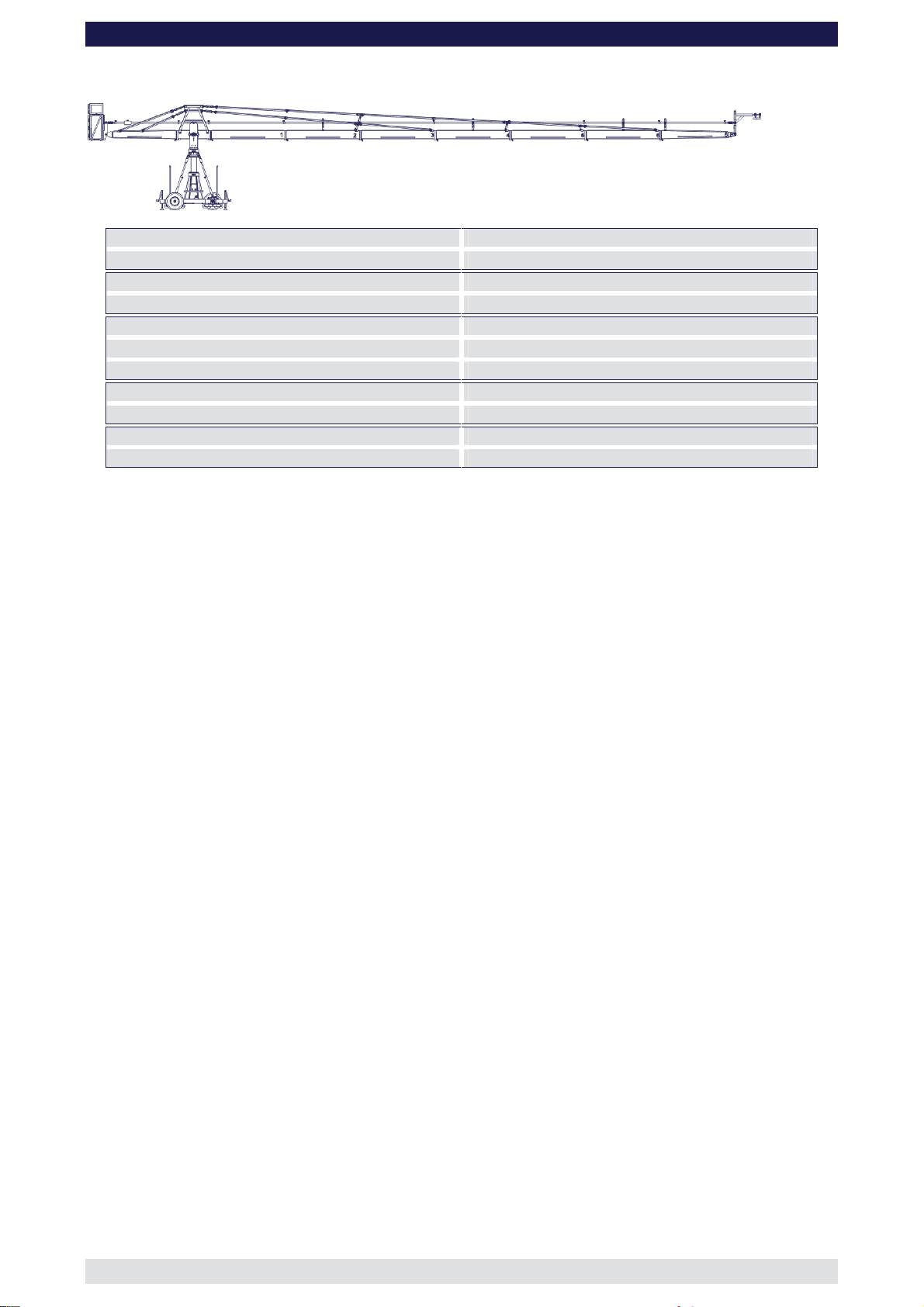
Version 13
GF-16 Crane System Instruction Manual
Front extension arms required 7 x 200 cm / 6' 6”
Rear extension arm required 1 x 192 cm / 6' 3”
Lift range 2269 cm / 74’ 5”
Maximum Euro-adapter height 1374 cm / 45'
Lift capacity (working load) camera + accessories 80 kg / 176 lbs
Counterweight required for max. load 1218 kg / 2679 lbs
Counterweight required to balance empty arm 722 kg / 1588 lbs
Crane weight (excluding dolly and weights) 895 kg / 1973 lbs
Dolly weight (unit weights see page 46) 244 kg / 536 lbs
Arm reach (pivot to camera head mount) 1483 cm / 48’ 7”
Length of rear end (pivot to outside of bucket) 278 cm / 9’ 1”
Continue from § 12, page 6
13. Connect the 200cm / 6’ 6” extension number 2 to extension number 1. Slip the
connection flanges into each other and secure with the provided safety pin.
Note: Section 2 must be supported by a suitable support stand or rostrum.
Tip: To avoid the sections jamming or getting stuck make sure that the sections
are joined parallel. Using a small amount of lubricant also helps. We suggest
rubbing the joints with an oiled rag prior to assembly.
14. Connect the 200cm / 6’ 6” extension number 3 to extension number 2. Slip the
connection flanges into each other and secure with the provided safety pin.
Note: Move the support stand or rostrum to support section number 3.
The “Rigging Harness Assembly” is described on page 9. After reading and
following the instructions, please proceed as follows.
15. Connect 2 turnbuckles to the bottom connection on the front side of the rigging
harness. Ensure that the locking pins are inserted fully.
16. Connect 2 standard rigging rods to the turnbuckles on the front side of the rigging
harness. Ensure that the locking pins are inserted fully.
17. Connect another 2 standard rigging rods to the first 2 rigging rods. Ensure that the
locking pins are inserted fully.
18. Connect 2 Rigging Support Brackets to the Rigging Rod Connections on section 2.
Ensure that the locking pins are inserted fully.
19. Connect a Rigging Rod Connector to each of the second Rigging Rods ensuring that
the locking pins are inserted fully. Fit the Rigging Rod Connectors into the Rigging
Support Brackets as shown on page 10.
20. Connect 2 standard rigging rods to the Rigging Rod Connectors and in turn to the
rigging connectors on section 3. Ensure that the locking pins are inserted fully.
21. Hand tighten the rods by turning the turnbuckles until the rods are taut, then secure
the turnbuckles with the locking nut as seen on page 9.
Attention: The rigging system when taut as well as the crane arm, should run in a
straight line and should not bend or dip.
22. When the Rigging Rods are taut and running in a straight line, insert the locking pin
connecting the Rigging Rod Connectors into the Rigging Support Brackets on section
3 as shown on page 10.
Page: 35
Page 37

GF-16 Crane System Instruction Manual
23. Connect the 200cm / 6’ 6” extension number 4 to extension number 3. Slip the
connection flanges into each other and secure with the provided safety pin.
24. Connect the 200cm / 6’ 6” extension number 5 to extension number 4. Slip the
connection flanges into each other and secure with the provided safety pin.
Note: Section 5 must be supported by a suitable support stand or rostrum.
25. Connect the 200cm / 6’ 6” extension number 6 to extension number 5. Slip the
connection flanges into each other and secure with the provided safety pin.
26. Place a support stand or rostrum under the end of extension number 6. Only remove
the support stand or rostrum supporting section 5 provided the support stand or
rostrum supporting section 3 is not removed.
27. Connect the Remote Extension to extension number 6. Slip the connection flanges
into each other and secure with the provided safety pin.
28. Connect a 200cm / 6’ 6” parallelogram rod to the parallelogram connection on the
middle section and secure it with the provided safety pin.
29. In turn, connect 5 x 200cm / 6’ 6” parallelogram rods to the first parallelogram
connection and secure them with the provided safety pins.
Note: Support the second, fourth and sixth parallelogram rod with the parallelogram
support located on sections 2, 4 and 6 and secure with the locking pin as
shown on page 10.
30. Connect the Remote Extension parallelogram rod to the last 200cm / 6’ 6”
parallelogram connection and secure it with the provided safety pin.
31. Support the Remote Extension parallelogram rod with the parallelogram support
located on the Remote Extension and secure with the locking pin as shown on
page 10.
32. Connect the Remote Bracket as described on page 43.
Tip: The Remote Bracket has an integrated leveller. By turning it, the Remote
Bracket can be set to a perfect right angle. Correct setting of the angle
adjuster enhances the crane’s balance.
33. Connect 2 turnbuckles to the top connection on the front side of the rigging harness.
Ensure that the locking pins are inserted fully.
34. Connect 2 standard rigging rods to the turnbuckles on the front side of the rigging
harness. Ensure that the locking pins are inserted fully.
35. Connect another 2 standard rigging rods to the first 2 standard rigging rods. Ensure
that the locking pins are inserted fully.
36. Connect 2 Rigging Support Brackets to the Rigging Support Brackets on section 2.
Ensure that the locking pins are inserted fully.
37. Connect a Rigging Rod Connector to each of the second Rigging Rods ensuring that
the locking pins are inserted fully. Fit the Rigging Rod Connectors into the Rigging
Support Brackets as shown on page 10.
38. Connect another 2 standard rigging rods to the Rigging Rod Connectors on the
second 2 standard rigging rods. Ensure that the locking pins are inserted fully.
39. Connect another 2 standard rigging rods to the third 2 standard rigging rods. Ensure
that the locking pins are inserted fully.
40. Connect 2 Rigging Support Brackets to the Rigging Rod Connections on section 4.
Ensure that the locking pins are inserted fully.
41. Connect a Rigging Rod Connector to each of the fourth Rigging Rods ensuring that
the locking pins are inserted fully. Fit the Rigging Rod Connectors into the Rigging
Support Brackets on section 4 as shown on page 10.
42. Connect 2 standard rigging rods to the Rigging Rod Connectors. Ensure that the
locking pins are inserted fully.
43. Connect 2 Rigging Rod Connectors to the fifth standard rigging rods. Ensure that the
locking pins are inserted fully.
Page: 36
Page 38

GF-16 Crane System Instruction Manual
44. Connect 2 standard rigging rods to the Rigging Rod Connectors and in turn to the
rigging connectors on section 6. Ensure that the locking pins are inserted fully.
45. Hand tighten the rods by turning the turnbuckles until the rods are taut, then secure
the turnbuckles with the locking nut as seen on page 9.
Attention: The rigging system when taut as well as the crane arm, should run in a
straight line and should not bend or dip.
46. When the Rigging Rods are taut and running in a straight line, insert the locking pin
connecting the Rigging Rod Connectors into the Rigging Support Brackets on section
2 and section 4 as shown on page 10.
47. Remove the support stand or rostrum supporting the counterweight bucket section.
48. Then unlock the tilt friction.
Before operation, all locking pins, locking screws etc should be inspected to ensure
that all assembly sections are securely fastened.
Read “Balancing the crane arm” on page 44.
Page: 37
Page 39

Version 14
GF-16 Crane System Instruction Manual
Front extension arms required 7 x 200 cm / 6' 6” + 1 x 100 cm / 3’ 3”
Rear extension arm required 1 x 192 cm / 6' 3”
Lift range 2424 cm / 79’ 6”
Maximum Euro-adapter height 1452 cm / 47' 7”
Lift capacity (working load) camera + accessories 80 kg / 176 lbs
Counterweight required for max. load 1394 kg / 3066 lbs
Counterweight required to balance empty arm 854 kg / 1878 lbs
Crane weight (excluding dolly and weights) 916 kg / 2019 lbs
Dolly weight (unit weights see page 46) 244 kg / 536 lbs
Arm reach (pivot to camera head mount) 1581 cm / 51’ 10”
Length of rear end (pivot to outside of bucket) 278 cm / 9’ 1”
Continue from § 12, page 6
13. Connect the 200cm / 6’ 6” extension number 2 to extension number 1. Slip the
connection flanges into each other and secure with the provided safety pin.
Note: Section 2 must be supported by a suitable support stand or rostrum.
Tip: To avoid the sections jamming or getting stuck make sure that the sections
are joined parallel. Using a small amount of lubricant also helps. We suggest
rubbing the joints with an oiled rag prior to assembly.
14. Connect the 200cm / 6’ 6” extension number 3 to extension number 2. Slip the
connection flanges into each other and secure with the provided safety pin.
Note: Move the support stand or rostrum to support section number 3.
The “Rigging Harness Assembly” is described on page 9. After reading and
following the instructions, please proceed as follows.
15. Connect 2 turnbuckles to the bottom connection on the front side of the rigging
harness. Ensure that the locking pins are inserted fully.
16. Connect 2 standard rigging rods to the turnbuckles on the front side of the rigging
harness. Ensure that the locking pins are inserted fully.
17. Connect another 2 standard rigging rods to the first 2 rigging rods. Ensure that the
locking pins are inserted fully.
18. Connect 2 Rigging Support Brackets to the Rigging Rod Connections on section 2.
Ensure that the locking pins are inserted fully.
19. Connect a Rigging Rod Connector to each of the second Rigging Rods ensuring that
the locking pins are inserted fully. Fit the Rigging Rod Connectors into the Rigging
Support Brackets as shown on page 10.
20. Connect 2 standard rigging rods to the Rigging Rod Connectors and in turn to the
rigging connectors on section 3. Ensure that the locking pins are inserted fully.
21. Hand tighten the rods by turning the turnbuckles until the rods are taut, then secure
the turnbuckles with the locking nut as seen on page 9.
Attention: The rigging system when taut as well as the crane arm, should run in a
straight line and should not bend or dip.
22. When the Rigging Rods are taut and running in a straight line, insert the locking pin
connecting the Rigging Rod Connectors into the Rigging Support Brackets on section
3 as shown on page 10.
Page: 38
Page 40

GF-16 Crane System Instruction Manual
23. Connect the 200cm / 6’ 6” extension number 4 to extension number 3. Slip the
connection flanges into each other and secure with the provided safety pin.
24. Connect the 200cm / 6’ 6” extension number 5 to extension number 4. Slip the
connection flanges into each other and secure with the provided safety pin.
Note: Section 5 must be supported by a suitable support stand or rostrum.
25. Connect the 200cm / 6’ 6” extension number 6 to extension number 5. Slip the
connection flanges into each other and secure with the provided safety pin.
26. Place a support stand or rostrum under the end of extension number 6. Only remove
the support stand or rostrum supporting section 5 provided the support stand or
rostrum supporting section 3 is not removed.
27. Connect the 100cm / 3’ 3” extension to extension number 6. Slip the connection
flanges into each other and secure with the provided safety pin.
28. Connect the Remote Extension to the 100cm / 3’ 3” extension. Slip the connection
flanges into each other and secure with the provided safety pin.
29. Connect a 200cm / 6’ 6” parallelogram rod to the parallelogram connection on the
middle section and secure it with the provided safety pin.
30. In turn, connect 5 x 200cm / 6’ 6” parallelogram rods to the first parallelogram
connection and secure them with the provided safety pins.
Note: Support the second, fourth and sixth parallelogram rod with the parallelogram
support located on sections 2, 4 and 6 and secure with the locking pin as
shown on page 10.
31. Connect the 100cm / 3’ 3” parallelogram rod to the last parallelogram connection and
secure it with the provided safety pin.
32. Connect the Remote Extension parallelogram rod to the 100cm / 3’ 3” parallelogram
connection and secure it with the provided safety pin.
33. Support the Remote Extension parallelogram rod with the parallelogram support
located on the Remote Extension and secure with the locking pin as shown on
page 10.
34. Connect the Remote Bracket as described on page 43.
Tip: The Remote Bracket has an integrated leveller. By turning it, the Remote
Bracket can be set to a perfect right angle. Correct setting of the angle
adjuster enhances the crane’s balance.
35. Connect 2 turnbuckles to the top connection on the front side of the rigging harness.
Ensure that the locking pins are inserted fully.
36. Connect 2 standard rigging rods to the turnbuckles on the front side of the rigging
harness. Ensure that the locking pins are inserted fully.
37. Connect another 2 standard rigging rods to the first 2 standard rigging rods. Ensure
that the locking pins are inserted fully.
38. Connect 2 Rigging Support Brackets to the Rigging Support Brackets on section 2.
Ensure that the locking pins are inserted fully.
39. Connect a Rigging Rod Connector to each of the second Rigging Rods ensuring that
the locking pins are inserted fully. Fit the Rigging Rod Connectors into the Rigging
Support Brackets as shown on page 10.
40. Connect another 2 standard rigging rods to the Rigging Rod Connectors on the
second 2 standard rigging rods. Ensure that the locking pins are inserted fully.
41. Connect another 2 standard rigging rods to the third 2 standard rigging rods. Ensure
that the locking pins are inserted fully.
42. Connect 2 Rigging Support Brackets to the Rigging Rod Connections on section 4.
Ensure that the locking pins are inserted fully.
43. Connect a Rigging Rod Connector to each of the fourth Rigging Rods ensuring that
the locking pins are inserted fully. Fit the Rigging Rod Connectors into the Rigging
Support Brackets on section 4 as shown on page 10.
Page: 39
Page 41

GF-16 Crane System Instruction Manual
44. Connect 2 standard rigging rods to the Rigging Rod Connectors. Ensure that the
locking pins are inserted fully.
45. Connect 2 Rigging Rod Connectors to the fifth standard rigging rods. Ensure that the
locking pins are inserted fully.
46. Connect 2 standard rigging rods to the Rigging Rod Connectors. Ensure that the
locking pins are inserted fully.
47. Connect 2 Rigging Rod Connectors to the sixth standard rigging rods. Ensure that the
locking pins are inserted fully.
48. Connect 2 100cm / 3’ 3” rigging rods to the Rigging Rod Connectors and in turn to the
rigging connectors on the 100cm / 3’ 3” section. Ensure that the locking pins are
inserted fully.
49. Hand tighten the rods by turning the turnbuckles until the rods are taut, then secure
the turnbuckles with the locking nut as seen on page 9.
Attention: The rigging system when taut as well as the crane arm, should run in a
straight line and should not bend or dip.
50. When the Rigging Rods are taut and running in a straight line, insert the locking pin
connecting the Rigging Rod Connectors into the Rigging Support Brackets on section
2, 4 and 5 as shown on page 10.
51. Remove the support stand or rostrum supporting the counterweight bucket section.
52. Then unlock the tilt friction.
Before operation, all locking pins, locking screws etc should be inspected to ensure
that all assembly sections are securely fastened.
Read “Balancing the crane arm” on page 44.
Page: 40
Page 42

Version 15
GF-16 Crane System Instruction Manual
Front extension arms required 8 x 200 cm / 6' 6”
Rear extension arm required 1 x 192 cm / 6' 3”
Lift range 2548 cm / 83’ 7”
Maximum Euro-adapter height 1531 cm / 50' 2”
Lift capacity (working load) camera + accessories 60 kg / 132 lbs
Counterweight required for max. load 1362 kg / 2996 lbs
Counterweight required to balance empty arm 938 kg / 2063 lbs
Crane weight (excluding dolly and weights) 927 kg / 2044 lbs
Dolly weight (unit weights see page 46) 244 kg / 536 lbs
Arm reach (pivot to camera head mount) 1681 cm / 55’ 1”
Length of rear end (pivot to outside of bucket) 278 cm / 9’ 1”
Continue from § 12, page 6
13. Connect the 200cm / 6’ 6” extension number 2 to extension number 1. Slip the
connection flanges into each other and secure with the provided safety pin.
Note: Section 2 must be supported by a suitable support stand or rostrum.
Tip: To avoid the sections jamming or getting stuck make sure that the sections
are joined parallel. Using a small amount of lubricant also helps. We suggest
rubbing the joints with an oiled rag prior to assembly.
14. Connect the 200cm / 6’ 6” extension number 3 to extension number 2. Slip the
connection flanges into each other and secure with the provided safety pin.
Note: Move the support stand or rostrum to support section number 3.
15. Connect the 200cm / 6’ 6” extension number 4 to extension number 3. Slip the
connection flanges into each other and secure with the provided safety pin.
The “Rigging Harness Assembly” is described on page 9. After reading and
following the instructions, please proceed as follows.
16. Connect 2 turnbuckles to the bottom connection on the front side of the rigging
harness. Ensure that the locking pins are inserted fully.
17. Connect 2 standard rigging rods to the turnbuckles on the front side of the rigging
harness. Ensure that the locking pins are inserted fully.
18. Connect 2 more standard rigging rods to the first rigging rods. Ensure that the locking
pins are inserted fully.
19. Connect 2 more standard rigging rods to the second rigging rods. Ensure that the
locking pins are inserted fully.
20. Connect 2 Rigging Support Brackets to the Rigging Rod Connections on section 3.
Ensure that the locking pins are inserted fully.
21. Connect a Rigging Rod Connector to each of the third Rigging Rods ensuring that the
locking pins are inserted fully. Fit the Rigging Rod Connectors into the Rigging
Support Brackets as shown on page 10.
22. Connect 2 standard rigging rods to the Rigging Rod Connectors and in turn to the to
the rigging connectors on section 4. Ensure that the locking pins are inserted fully.
23. Hand tighten the rods by turning the turnbuckles until the rods are taut, then secure
the turnbuckles with the locking nut as seen on page 9.
Page: 41
Page 43

GF-16 Crane System Instruction Manual
Attention: The rigging system when taut as well as the crane arm, should run in a
straight line and should not bend or dip.
24. When the Rigging Rods are taut and running in a straight line, insert the locking pin
connecting the Rigging Rod Connectors into the Rigging Support Brackets on section
3 as shown on page 10.
25. Connect the 200cm / 6’ 6” extension number 5 to extension number 4. Slip the
connection flanges into each other and secure with the provided safety pin.
Note: Section 5 must be supported by a suitable support stand or rostrum.
26. Connect the 200cm / 6’ 6” extension number 6 to extension number 5. Slip the
connection flanges into each other and secure with the provided safety pin.
27. Place a support stand or rostrum under the end of extension number 6. Only remove
the support stand or rostrum supporting section 5 provided the support stand or
rostrum supporting section 3 is not removed.
28. Connect the 200cm / 6’ 6” extension number 7 to extension number 6. Slip the
connection flanges into each other and secure with the provided safety pin.
29. Connect the Remote Extension to extension number 7. Slip the connection flanges
into each other and secure with the provided safety pin.
30. Connect a 200cm / 6’ 6” parallelogram rod to the parallelogram connection on the
middle section and secure it with the provided safety pin.
31. In turn, connect 6 x 200cm / 6’ 6” parallelogram rods to the first parallelogram
connection and secure them with the provided safety pins.
Note: Support the second, fourth and sixth parallelogram rod with the parallelogram
support located on sections 2, 4 and 6 and secure with the locking pin as
shown on page 10.
32. Connect the Remote Extension parallelogram rod to the last 200cm / 6’ 6”
parallelogram connection and secure it with the provided safety pin.
33. Support the Remote Extension parallelogram rod with the parallelogram support
located on the Remote Extension and secure with the locking pin as shown on
page 10.
34. Connect the Remote Bracket as described on page 43.
Tip: The Remote Bracket has an integrated leveller. By turning it, the Remote
Bracket can be set to a perfect right angle. Correct setting of the angle
adjuster enhances the crane’s balance.
35. Connect 2 turnbuckles to the top connection on the front side of the rigging harness.
Ensure that the locking pins are inserted fully.
36. Connect 2 standard rigging rods to the turnbuckles on the front side of the rigging
harness. Ensure that the locking pins are inserted fully.
37. Connect another 2 standard rigging rods to the first 2 standard rigging rods. Ensure
that the locking pins are inserted fully.
38. Connect a Rigging Rod Connector to each of the second Rigging Rods ensuring that
the locking pins are inserted fully.
39. Connect a third Rigging Rod to each of the Rigging Rod Connectors ensuring that the
locking pins are inserted fully.
40. Connect 2 Rigging Support Brackets to the Rigging Support Brackets on section 3.
Ensure that the locking pins are inserted fully.
41. Connect a Rigging Rod Connector to each of the third Rigging Rods ensuring that the
locking pins are inserted fully. Fit the Rigging Rod Connectors into the Rigging
Support Brackets on section 3 as shown on page 10.
42. Connect another 2 standard rigging rods to the Rigging Rod Connectors on the third 2
standard rigging rods. Ensure that the locking pins are inserted fully.
43. Connect another 2 standard rigging rods to the
fourth
2 standard rigging rods. Ensure
that the locking pins are inserted fully.
Page: 42
Page 44

GF-16 Crane System Instruction Manual
44. Connect 2 Rigging Support Brackets to the Rigging Rod Connections on section 5.
Ensure that the locking pins are inserted fully.
45. Connect a Rigging Rod Connector to each of the fifth Rigging Rods ensuring that the
locking pins are inserted fully. Fit the Rigging Rod Connectors into the Rigging
Support Brackets on section 5 as shown on page 10.
46. Connect 2 standard rigging rods to the Rigging Rod Connectors. Ensure that the
locking pins are inserted fully.
47. Connect 2 Rigging Rod Connectors to the sixth standard rigging rods. Ensure that the
locking pins are inserted fully.
48. Connect 2 standard rigging rods to the Rigging Rod Connectors and in turn to the
rigging connectors on section 7. Ensure that the locking pins are inserted fully.
49. Hand tighten the rods by turning the turnbuckles until the rods are taut, then secure
the turnbuckles with the locking nut as seen on page 9.
Attention: The rigging system when taut as well as the crane arm, should run in a
straight line and should not bend or dip.
50. When the Rigging Rods are taut and running in a straight line, insert the locking pin
connecting the Rigging Rod Connectors into the Rigging Support Brackets on section
3 and section 5 as shown on page 10.
51. Remove the support stand or rostrum supporting the counterweight bucket section.
52. Then unlock the tilt friction.
Before operation, all locking pins, locking screws etc should be inspected to ensure
that all assembly sections are securely fastened.
Read “Balancing the crane arm” on page 44.
Remote Head Mount
1. The Remote Head Mount is connected to the remote “nose” section.
Mounting connection
Remote Mount Leveller
2. Connect the Remote Mount to the
connection bolts on the nose section and
lock securely.
3. Connect the Remote Mount Leveller to the
Remote Parallelogram rod.
4. Secure the Remote Mount Leveller to the
Remote Parallelogram rod by inserting the
locking pin. Level the Remote Mount as
needed.
bolts
Page: 43
Page 45

GF-16 Crane System Instruction Manual
Balancing the crane arm
Attention: When loading the crane the maximum working load
capacities and payloads must never be exceeded.
Note: Do not load weights until the rigging system is mounted.
After the assembly procedure has been completed the seat arms, seats, risers, camera etc
may now be assembled on the platform or the remote head system may be mounted. An
itemized weight list for GFM accessories may be found below. Place the correct
amount of counterweight in the weight bucket to balance the load. The counterweights
should not be thrown into the bucket but rather placed softly in the bucket. When the arm
is balanced, the camera operator / operators can then take their position on the platform.
Attention: The safety belts provided must be fastened upon sitting
down and kept fastened at all times when on the platform.
Only original GFM seats, seat arms, risers etc may be used.
Working load capacity = Camera operator / operators + accessories
Place the required amount of counterweights in the weight bucket so that the crane arm
becomes balanced and remains in the horizontal position. If necessary, the crane can be
fine balanced by adjusting the sliding weight on the rear parallelogram at the weight
bucket. Do not forget to lock the sliding weight in position before tilting the arm.
The counterweight bucket door must be locked when operating the crane.
Deloading:
Attention: When dismantling the crane it is essential that the platform
is supported fully by a stable underlay i.e. rostrum or
ground surface. In any case the platform should not be in
the air without support.
Attention: The counterweights must always be gradually removed
from the counterweight bucket before personnel leave the
platform.
When the weights are removed, the platform personnel should dismount one at a time but
only after being instructed to do so by the crane operator. At all times, extreme caution
must be given to the shifting payload.
General Safety
Attention: All necessary precautions should be taken so that
unauthorized third parties cannot use or operate the crane
and also to ensure that only authorized personnel have
access to it.
Operational conditions:
At a wind speed of 25 km/h – 15.6 mph crane operation must be stopped and the crane
secured, dismounted and the necessary safety precautions taken.
If it, for example, takes 2 mins. to unload the counterweights and take the necessary
precautions to secure the crane, one must commence with the procedure at a wind speed
of 20 km/h – 12.4 mph. DIN15019, part 1, section 6.13.
The crane may not be used in a lightening storm as there is the danger of electrocution.
Page: 44
Page 46

GF-16 Crane System Instruction Manual
Positioning the Adjustable Mounting Column
1. When the crane is assembled, the Adjustable Mounting Column may be driven to it’s
full height. The column may either be hand cranked or driven with a 24V battery
driven screwdriver. We suggest you drive the screwdriver at speed 1. The connection
on the column is a 24mm, male hexagonal head.
Important: When adjusting the height of the column make sure that
the 4 Adjustable Stabilizing Rods can move freely and that
they are not restricted in travel. The Rod Locking Pin found
in the middle of each rod must be removed when adjusting
the height and reinserted only when the column is in the
required position.
Rod Locking Pins
STOP Mark
Rod Locking Nut
Important: When driving the column upwards, do not go past the
“STOP” mark engraved on the column.
2. When the column is in the required position, insert the 4 Rod Locking Pins into the
middle of each rod. Adjust the 4 rods until they are stiff, then counter lock with the
locking nuts found at end of each stabilizing rod (total of 8).
Page: 45
Page 47

Description
GF-16 Camera Crane and Dolly Dimensions
GF-16 Crane System Instruction Manual
Dolly weight
Weight
kg
Dolly Base
Levelling leg set (4 pcs.)
Track wheel set (4 pcs.)
Base Dolly push bar
Complete Dolly weight
Adjustable Mounting column with
rotateable bearing
Stabilizing rod set (4 pcs.) 11 kg
186 kg
28 kg
24 kg
6 kg
244 kg
136 kg
Weight
lbs
410 lbs
61 lbs
53 lbs
13 lbs
536 lbs
300 lbs
24 lbs
Page: 46
Page 48

Accessories for GF- 16 crane
GF-16 Crane System Instruction Manual
Track wheel with brake
Push bar
Levelling leg
Utensil tray
Notice:
When operating the crane with the push bar mounted on the dolly, pay attention that the
crane arm at no time collides with the push bar.
Always use the levelling legs to level the crane when on uneven surfaces. For safety
reasons only original accessories manufactured by GFM may be used with the crane.
Accessories for GF-16 Crane platform weight list
Qty. Description Weight kg Weight lbs
1
1
1
1
1
1
1
1
1
1
1
1
1
1
Seat arm combined 10cm / 4"
Seat arm combined 20cm / 8"
Seat arm combined 30cm / 12"
Seat arm vertical 10cm / 4"
Seat arm vertical 20cm / 8"
Seat arm vertical 30cm / 12"
Crane seat with seat belt
Riser 10 cm / 4"
Riser 20cm / 8"
Riser 30cm / 12"
Riser 40cm / 16"
Riser 50cm / 20"
Connection pin
Ball Adapter
AL-2210 0,75 kg 1,65 lbs
AL-2220 1,15 kg 2,53 lbs
AL-2230 1,60 kg 3,52 lbs
AL-2211 1,25 kg 2,75 lbs
AL-2212 1,75 kg 3,85 lbs
AL-2213 2,20 kg 4,84 lbs
AL-1030 7,20 kg 15,84 lbs
AL-2310 2,80 kg 6,16 lbs
AL-2320 2,95 kg 6,49 lbs
AL-2330 3,40 kg 7,48 lbs
AL-2340 3,80 kg 8,36 lbs
AL-2350 4,25 kg 9,35 lbs
AL-2240 0,40 kg 0,88 lbs
AL-2150 2,17 kg 4,77 lbs
Page: 47
Page 49
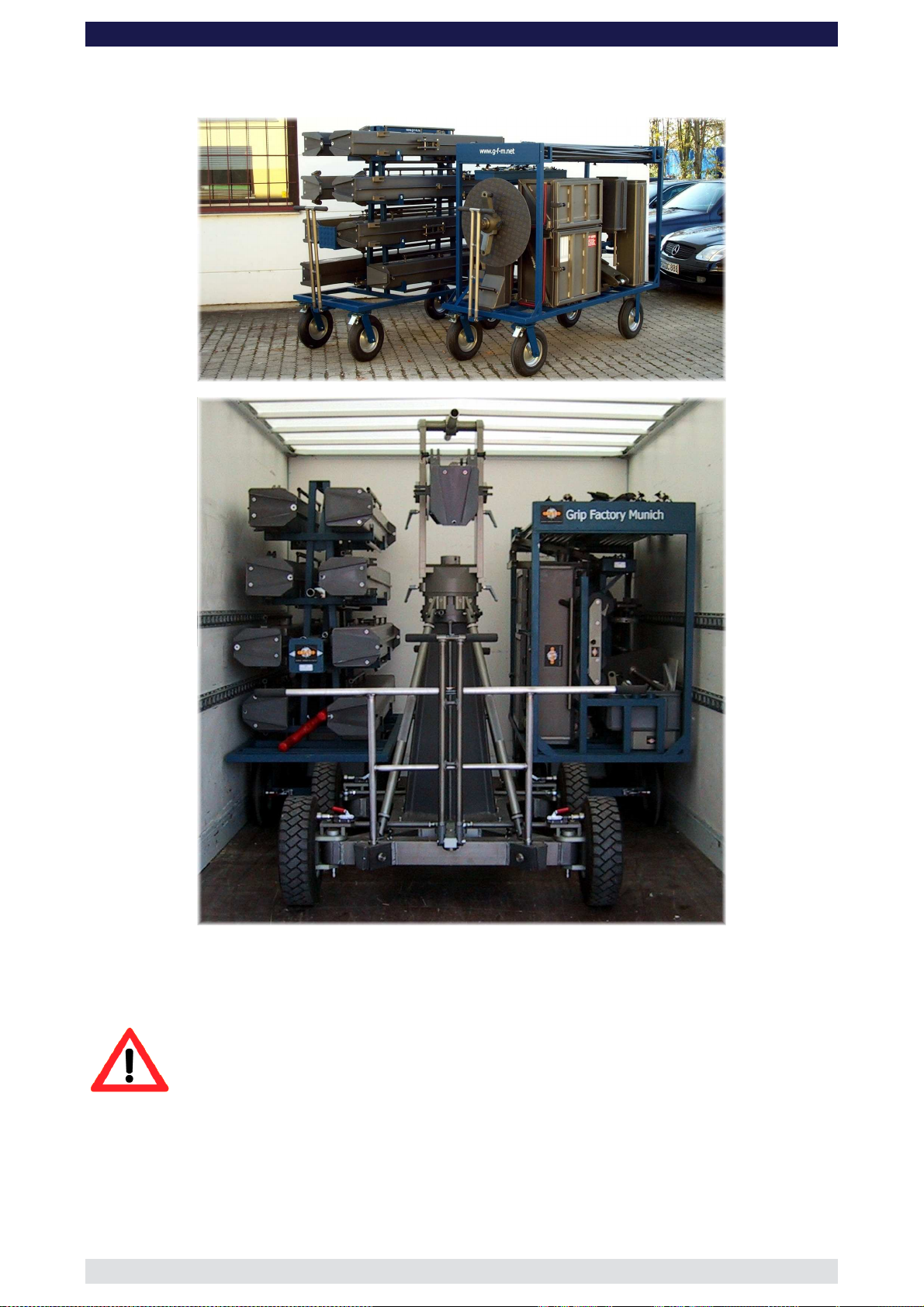
Transport trolley for the GF-16 Crane
GF-16 Crane System Instruction Manual
The above photos show the practical transport solution for the GF-16 Crane System. The
GFM trolleys fits the complete system with dolly and column as an extra unit.
Attention: After loading and unloading the GF-16 Crane System the
wheel brakes have to be locked.
Page: 48
Page 50

GF-16 Crane System Instruction Manual
Maintaining the Adjustable Column
The GF-16 Crane has an adjustable column which provides a vertical lift of 400mm. This
lift is achieved through an elevating gear which should be inspected at regular yearly
intervals.
In general, maintenance work should only be carried out by competent personnel,
observing at all times the safety regulations and recognized safety guidelines. After using
the column we recommend cleaning it with WD40.
Dismantling the column:
The column should be dismantled as per the following steps:
1. Remove the adjustable stabilizing rods and in turn remove the column (see page 4).
2. Remove the rotateable bearing by opening the bolts.
3. Extend the column until the STOP mark is visible. Using extreme caution, lay the
column on its side (attention, danger of damaging the column).
4. Dismantling the drive shaft.
5. Remove the plastic cover which protects the friction and release the friction.
6. Remove the 8 bolts at the bottom of the ground plate.
7. Remove the spindle unit through the bottom of the column (extreme care should be
taken to not damage the spindle).
Page: 49
Page 51
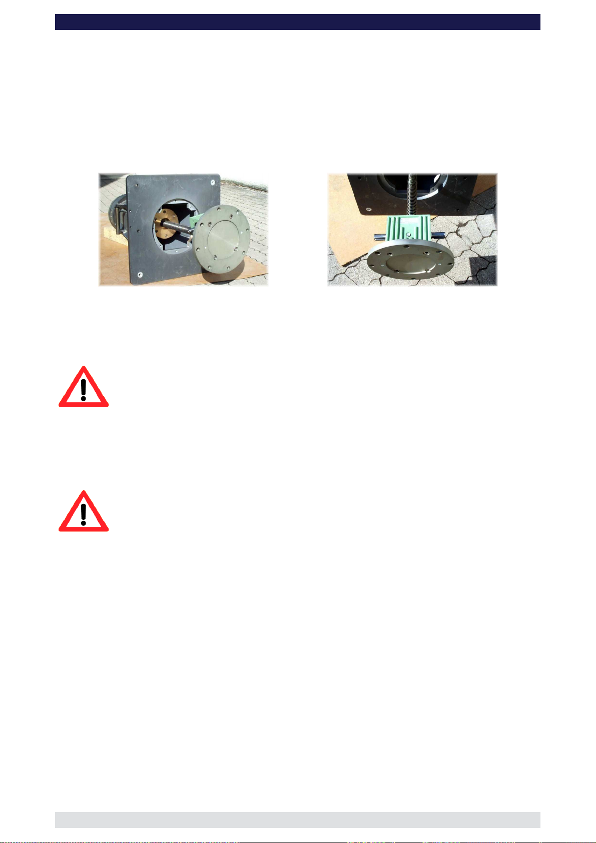
GF-16 Crane System Instruction Manual
Maintenance
At yearly intervals, the spindle must be cleaned and all grease removed and replaced with
generous quantities of fresh grease (e.g. gleitmo 805, gleitmo 585M, Fa. Fuchs Lubritech
GmbH).
The lubricating nipple on the lift gear (bright green) must also be greased yearly (e.g. Mobil
grease XHP).
Wear and tear on the spindle nut must also be annually inspected. This can be done as
per in the above picture by moving the components against each other. If there is more
than 2mm of play, the spindle drive or the spindle nut must be replaced otherwise further
use is not allowed.
Attention: Danger of crushing while tilting the column and sliding it to
check the wear and tear.
When reassembling the column it should be noted that the friction should only be screwed
in so far as to allow it move up and down easily and reduce any rotation of the column.
Furthermore, when operating the column pay close attention to the ease of movement and
any changes that occur in the movement.
Attention: For safety reasons only original spare parts by GFM may
be used for maintenance and raparation!
Page: 50
Page 52

GF-16 Crane System Instruction Manual
Regular Inspections
According to guideline BGV C1, § 34, repeated inspections by a technical expert must be
carried out at least once every year. In addition, inspection through a technical expert,
based on the scope of examination must be carried out every 4 years. The inspections
must be registered in the Log Book that is delivered with each crane.
Technical experts must meet the requirements of BGV C1, §34 and §36 according to the
following explanation:
A technical expert for the annual inspection is a person who, based on their training and
experience has sufficient knowledge in:
- Areas of technical safety and machinery as well as the State’s related protective
regulations for the work place.
- Rules and regulations from the respective government safety organization.
- Recognized regulations and generally recognized technical rules and accepted
technical codes of practice (e.g. DIN norms, VDE regulations, technical rules of
other European Union members States or other States that comply with the Treaty
on the European Economic Area)
- Work related safety standards and technical safety for machinery.
Valid as a technical expert for the inspection of technical safety and machine facilities
every 4 years is an expert recognized by the government safety organization. In general,
the authorisation of a recognized technical expert requires the following:
a) Completed studies as an Engineer
b) A minimum of 3 years experience in construction design, assembly or maintenance
of safety relevant and technical facilities.
It is recommended that the safety inspections be carried out by GFM or a local recognized
expert.
Contact details of domestic and foreign technical experts can be obtained from recognized
technical surveillance organizations (e.g. TÜV).
Page: 51
Page 53

GF-16 Crane System Instruction Manual
EC Declaration of Conformity
The company Grip Factory Munich GmbH
Fürholzener Str. 1
D-85386 Eching
declares, that the crane Type: GF-16
Model: Cameracrane
Serial No. and year of manufacturing:
see identification plate
complies with the machine guidelines 2006/42/EG (May 2006)
This EC Declaration of Conformity will become invalid should the crane be in any way
modified and the modifications not be authorized by us in writing.
Eching, March 2010 .......................................................
Antonio Tundo – Technical Director
Page: 52
 Loading...