

Page 1

1
OPERATOR’S MANUAL
AND PARTS LIST
MODEL GRTCR175 ROOFING NAILER
Distributed By
Tough as nails
www.grip-rite.com
Page 2
32
TABLE OF CONTENTS
TABLE OF CONTENTS -------------------------------- 2
SPECIFICATIONS --------------------------------------- 3
SAFETY ---------------------------------------------------- 4
TOOL PARTS --------------------------------------------- 8
PART DESCRIPTIONS--------------------------------- 9
OPERATION--------------------------------------------- 10
Loading Fasteners ------------------------------- 10
Adjusting Nail Drive ------------------------------- 11
Clearing Nail Jams -------------------------------- 11
Tool Operation------------------------------------- 12
Shingle Guide Adjustment --------------------- 13
MAINTENANCE ---------------------------------------- 13
PARTS SCHEMATIC---------------------------------- 14
PARTS LIST --------------------------------------------- 15
TROUBLESHOOTING ------------------------------- 16
TOOL CHECKS ---------------------------------------- 17
WARRANTY --------------------------------------------- 18
SPECIFICATIONS
SPECIFICATIONS
MODEL GRTCR175 COIL ROOFING NAILER
FASTENER RANGE 3/4” - 1 3/4” (19mm - 44.5 mm)
FASTENER TYPE 15° WIRE WELD COIL ROOFING NAILS
MAGAZINE CAPACITY 1 COIL - 120 NAILS
MAX AIR PRESSURE 120 psi (8.3 bar)
MIN AIR PRESSURE 70 psi (4.8 bar)
TOOL WEIGHT 4.86 lbs. (1.8 kg)
TOOL LENGTH 9 1/2” (24.1 cm)
TOOL HEIGHT 11” (28 cm)
TOOL WIDTH 4.6” (11.6 cm)
TRIGGER TYPE STD. DUAL ACTION
AIR INLET 3/8 NPT
AIR CONNECTION MALE QUICK CONNECT COUPLER
LUBRICATION 10W Air Tool Oil (Provided)
NOISE CHARACTERISTIC VALUES IN ACCORDANCE WITH ISO 3774, ISO 11201:
A-weighted single-event sound
pressure level at operator’s position ---------------------------------- LpA, 1s = 91 dBA
A-weighted single-event sound power level ----------------------- LwA, 1s = 102 dBA
A-weighted single-event surface sound
pressure level ---------------------------------------------------------------- LpA, 1s = 89 dBA
VIBRATION CHARACTERISTIC VALUES IN ACCORDANCE WITH ISO 8862-1
Weighted root mean square acceleration ---------------------------- = 2.7 m/s
2
IMPORTANT SAFETY INFORMATION
You must read this entire manual and familiarize yourself with all
safety, operating, and service instructions before loading, handling,
or using your tool. When used correctly, pneumatic fastening
tools provide a lightweight, powerful, and safe means of fastening.
Used improperly, these tools can cause serious injury to you and
those around you.
For best results, use only Grip-Rite™ collated fasteners.
FASTENER SELECTION CHART
SIZE BOX QTY. ELECTROGALVANIZED STAINLESS STEEL
SMOOTH SHANK SKU RING SHANK SKU
3/4” (19 mm) 7.2M GRCR19GAL N/A
7/8” (22 mm) 7.2M GRCR2DCGAL N/A
1” (25 mm) 7.2M GRCR2DGAL N/A
1-1/4” (32 mm) 7.2M GRCR3DGAL GRCR3DRSS
1-1/2” (38 mm) 7.2M GRCR4DGAL GRCR3DRSS
1-3/4” (44 mm) 7.2M GRCR5DGAL N/A
Page 3
54
SAFETY
SAFETY
WEAR SAFETY GLASSES
Always wear safety glasses with side shields that meet ANSI
Z87.1 requirements when operating the tool. Make sure all
others in work area wear safety glasses.
WEAR HEARING PROTECTION
Wear hearing protection to protect your hearing from noise.
Prolonged exposure to loud noise can result in hearing loss.
NEVER OPERATE THE TOOL WITH OXYGEN OR OTHER
BOTTLED GASES
Oxygen and other reactive or high-pressure bottled gases
can cause the tool to explode. Use clean, dry regulated
compressed air from a properly operating air compressor.
DO NOT EXCEED MAXIMUM RECOMMENDED OPERATING AIR
PRESSURE OF 120 PSI /8.3 Bar.
Exceeding the maximum recommended air pressure can
cause the tool housing to burst, or cause premature failure of
components.
NEVER CONNECT THE TOOL TO AN AIR SUPPLY THAT HAS
THE
POTENTIAL TO EXCEED 180 PSI/12.4 Bar.
Using a regulated air supply with a line or tank pressure
greater than 180 psi can cause the tool to burst if the air line
regulator fails suddenly.
USE AN AIR HOSE RATED FOR 180 PSI/12.4 Bar OR
GREATER
Always use air hose rated to handle 180 psi or the maximum
potential pressure of the air supply.
ONLY USE A RELIEVING-TYPE AIR COUPLING IN THE TOOL
AIR INLET OPENING.
Use of a non-relieving air coupling on the tool can trap air
inside the tool housing, and allow the tool to drive a fastener
even after the air hose has been disconnected.
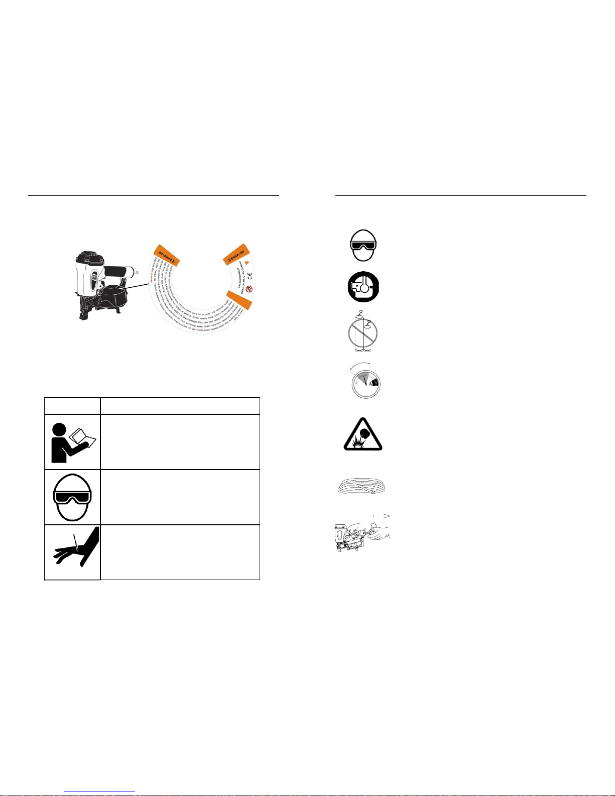
SAFETY LABELS
This pneumatic fastening tool includes a warning label to help remind you of
important safety information when operating the tool. The safety label must be
legible at all times, and must be replaced if it becomes worn or damaged.
SAFETY SYMBOLS
These safety symbols provide a visual reminder of basic safety
rules, and the personal injury hazard that may arise if all safety and
operating instructions are not followed. Make sure you understand
the meaning of each of these symbols, and protect yourself and
others by obeying all safety and operating instructions.
SYMBOL
DESCRIPTION
READ THE MANUAL - The manual contains
important safety and operating instructions
that must be followed. All tool users must
read the manual before using the tool.
WEAR SAFETY GLASSES - Tool operator
and bystanders must wear safety glasses
with side shield that meet ANSI Z87.1
requirements.
RISK OF PERSONAL INJURY - Failure to
follow all safety and operating instructions,
or misuse of the tool, can result in serious
injury to tool operator and bystanders.
SAFETY INSTRUCTIONS
120 psi
4.9 bar
70 psi
8.3 bar
Page 4
76
SAFETY
SAFETY
DO NOT ATTEMPT TO OPERATE THE TOOL IF THE TOOL’S
OPERATING CONTROLS HAVE BEEN MODIFIED OR ARE NOT
WORKING PROPERLY.
Attempting to use a tool with modified or malfunctioning
trigger or workpiece contact can result in a fastener being
driven unintentionally.
USE CORRECT FASTENERS
Only use the correct fastener for the tool. Using fasteners
with incorrect specifications can jam the tool or cause
serious injuries.
USE THE CORRECT FASTENERS FOR THE APPLICATION.
Using the wrong fasteners can cause the workpiece to split
and allow the fastener to fly free.
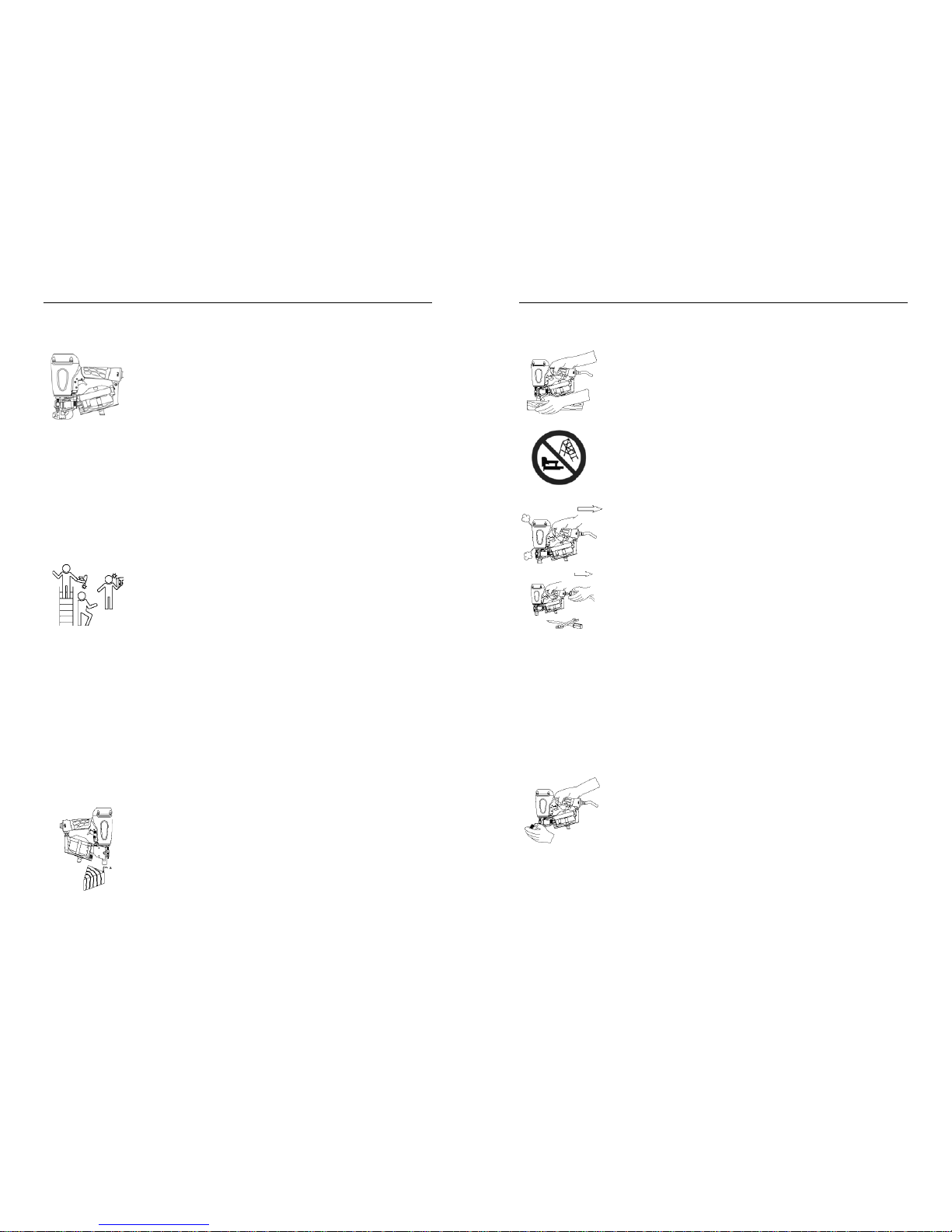
KEEP TOOL POINTED IN A SAFE DIRECTION WHEN LOADING
FASTENERS.
Never point the tool at yourself or anyone else when loading
fasteners.
DO NOT LOAD TOOL WITH TRIGGER OR WORKPIECE
CONTACT
DEPRESSED.
Depressing the trigger or workpiece contact during loading
can result in an unintentional fastener drive if both devices
are accidentally actuated at the same time.
KEEP FINGER OFF TRIGGER UNTIL TOOL IS IN POSITION TO
DRIVE
A FASTENER.
An unexpected bump or sudden contact with your body or that
of a bystander can result in serious injuries.
AVOID DRIVING FASTENERS INTO KNOTS, ON TOP OF
OTHER FASTENERS, AT WORKPIECE EDGES, OR INTO
BRITTLE MATERIALS.
Driving fasteners into extremely hard materials, or driving into
workpiece edges, can cause fasteners to deflect away from
the workpiece. Flying fasteners can cause serious injuries.
KEEP HANDS AND BODY PARTS AWAY FROM AREA BEING
FASTENED.
Fasteners can deflect and turn as they are being driven into
the workpiece, and penetrate fingers, hands, and other body
parts that may be in the fastening area.
DO NOT OVERREACH OR WORK WHILE ON UNSTABLE
FOOTING
If you lose your balance while fastening, you could drive a
fastener into yourself or a bystander.
DO NOT USE TOOL IF TOOL MALFUNCTIONS OR BEGINS
LEAKING AIR.
Operating a malfunctioning tool can result in an unexpected
fastener discharge and injury to yourself or others.
DISCONNECT THE TOOL FROM THE AIR SUPPLY TO RELOAD, CLEAR JAMS, OR PERFORM MAINTENANCE.
Never attempt to reload a tool, clear a jam, or perform
maintenance without first disconnecting the air supply.
NEVER LEAVE A LOADED, PRESSURIZED TOOL UNATTENDED
A loaded, pressurized tool could be picked up or handled by
someone who is unfamiliar with the tool or that has not read
the tool manual.
KEEP TOOLS OUT OF THE REACH OF CHILDREN
Place the tool back in the tool box after use, and store the tool
out of reach.
DO NOT MODIFY TOOL
Modifications can cause a tool to be unsafe and can cause
the tool to operate improperly.
SAFETY INSTRUCTIONS
SAFETY INSTRUCTIONS
Page 5
98
DESCRIPTION
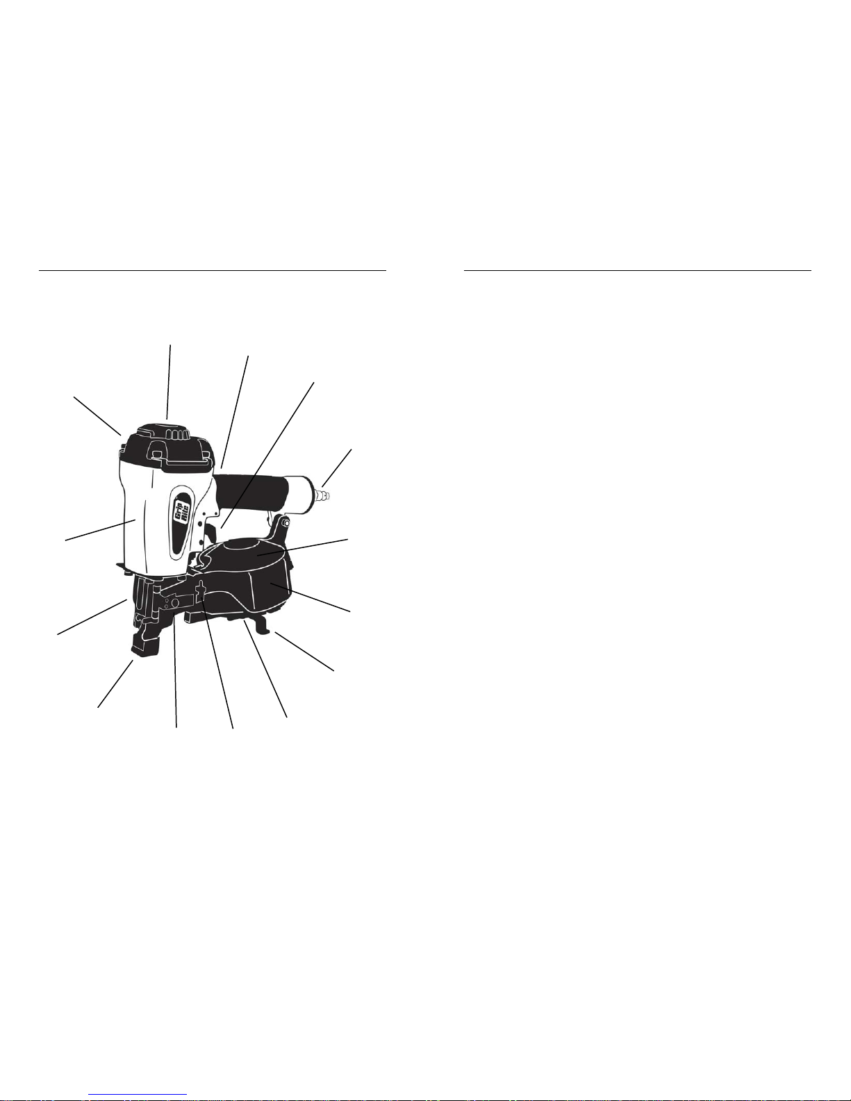
PART DESCRIPTIONS
1. 360° Adjustable Air Deflector - Tool-free adjustment blows exhaust
air away from operator. 12 locking positions for secure settings.
2. Cushioned Grip - Cushioned handgrip reduces fatigue and provides
comfortable operation.
3. Dual Action Trigger - Actuates tool when workpiece contact is
depressed against work surface. Permits contact-trip (bump fire) or
trigger-fire operation.
4. Air Coupling - Quick-disconnect male coupling allows quick
connection to air hose. Dust cap keeps dirt out when tool is not in
use.
5. Safety Warning Label - Provides important safety reminders that
must be followed whenever handling, operating, or servicing the tool.
6. Coil Nail Magazine - Hold fasteners securely and protects coils
from damage. Adjusts quickly to handle different length fasteners.
7. Shingle Guide - Adjustable shingle guide provides consistent
shingle exposure for fast, accurate work.
8. Adjustable Fastener Tray - Adjustable tray supports different
fastener lengths for positive, trouble-free feeding.
9. Door Latch - Spring-loaded latch keeps door securely closed.
Opens quickly for fast, easy reloading of nail coils.
10. Dual Feed Pawl System - Dual feed pawl system provides consis-
tent nail feed.
11. Workpiece Contact - Spring-loaded contact mechanism prevents
tool from driving a fastener unless tool is pressed down and held
against a work surface. Carbide steel inserts resist wear and extend
part life.
12. Debris Shield - Prevents wood chips and debris from flying toward
operator.
13. Tool Housing - Magnesium tool housing reduces tool weight
14. Cap - Seals tool housing.
Metric Hex Wrenches - Included with tool to allow tightening of
metric screws. Keep tools in tool case for periodic tightening of
screws.
Air Tool Oil - Lightweight oil formulated for use in air tools provides
proper lubrication to o-rings and internal parts.
Safety Goggles - Provide required eye protection
DESCRIPTION
TOOL PARTS
1
2
3
12
5
8
6
11
10
9
7
4
14
13
Page 6
1110
OPERATION
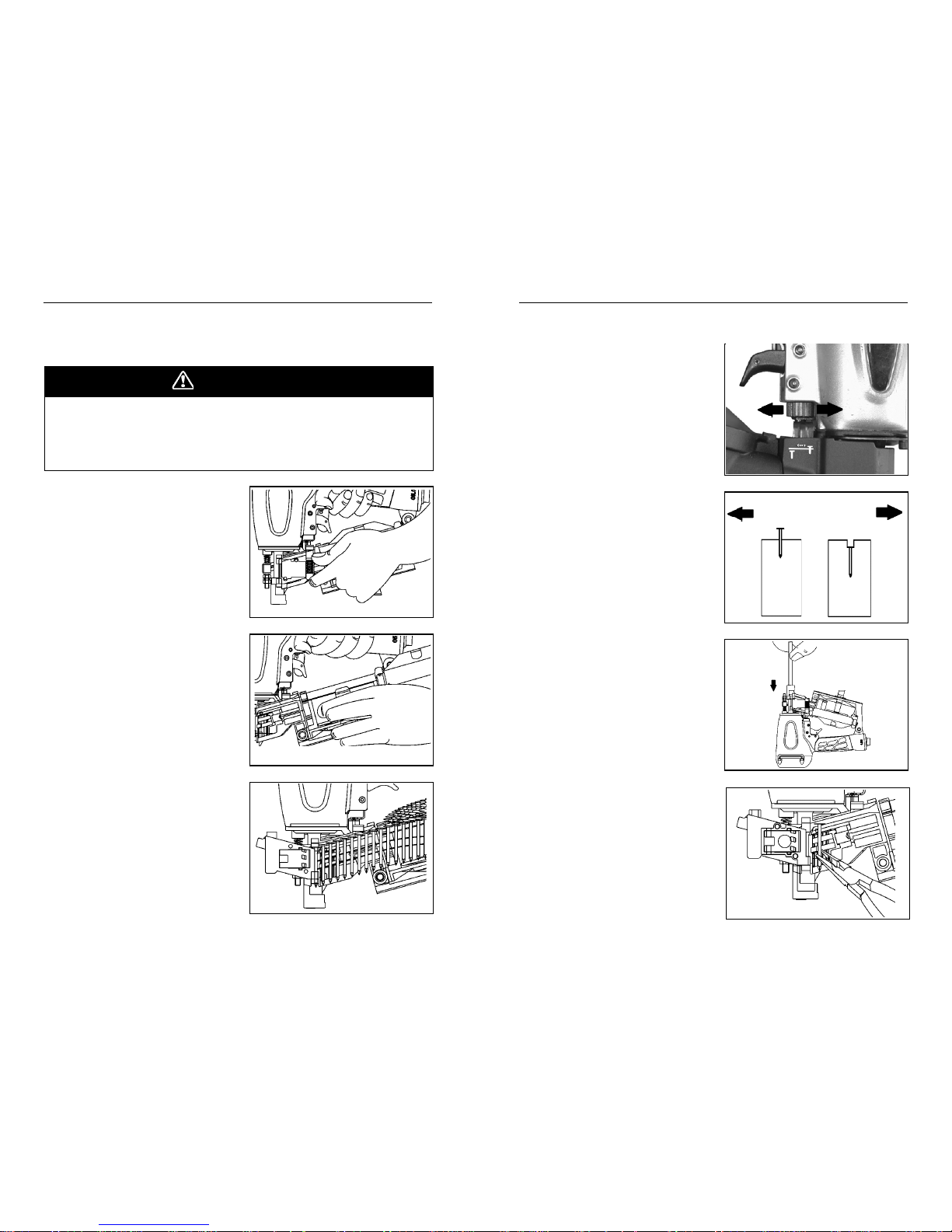
ADJUSTING NAIL DRIVE
1. Disconnect tool from air supply
using quick-connect coupling.
2. Turn adjustment dial backward
to increase nail drive, or forward
to decrease nail drive, as
shown by nail symbols on tool.
3. Connect tool to air supply, and
drive nails to check for correct
depth of drive.
4. Make depth of drive adjustments as needed to maintain
consistent nail driving.
5. NEVER drive nail heads
through roofing shingles, tar
paper, or other materials being
fastened.
CLEARING NAIL JAMS
1. Disconnect tool from air supply
using quick-connect coupling.
2. Open door, remove nails from
drive channel and feed pawl.
3. Insert rod into nose bore, and
push nail back through drive
channel and out of guide body.
If necessary, tap rod lightly with
a hammer to free jammed nail.
4. Remove nail from drive channel
using pliers.
OPERATION
LOADING FASTENERS
LOADING INSTRUCTIONS
1. Depress door latch and open
door. Swing magazine cover
open.
2. Check nail holder position, and
adjust as needed for nail
length being driven.
3. To adjust, pull up on center
post, and twist holder to
desired setting using nail
length indicators inside
magazine.
4. Place coil of nails over center
post. Uncoil enough nails to
reach feed pawl, and pull out
toward tool nose.
5. Place first nail in nail drive
channel, and position second
nail between teeth of feed
pawl. Nail heads must be
aligned in nail head groove.
6. Close magazine cover, and
latch door securely.
7. Roofing nailer is now loaded
and ready to be connected to
an air supply for operation.
A fastener can be driven unintentionally if the trigger and safety bracket
are activated at the same time. Always disconnect tool from air supply
before loading fasteners, making adjustments, or performing any service
on tool. Keep finger off trigger until ready to drive a fastener.
DANGER
NAIL TOO HIGH
TURN DIAL
BACKWARD
NAIL TOO DEEP
TURN DIAL
FORWARD
Page 7
1312
MAINTENANCE
MAINTENANCE
Your tool will last longer and perform better if periodic maintenance is
performed. Please use the information below to keep your tool operating
in top condition.
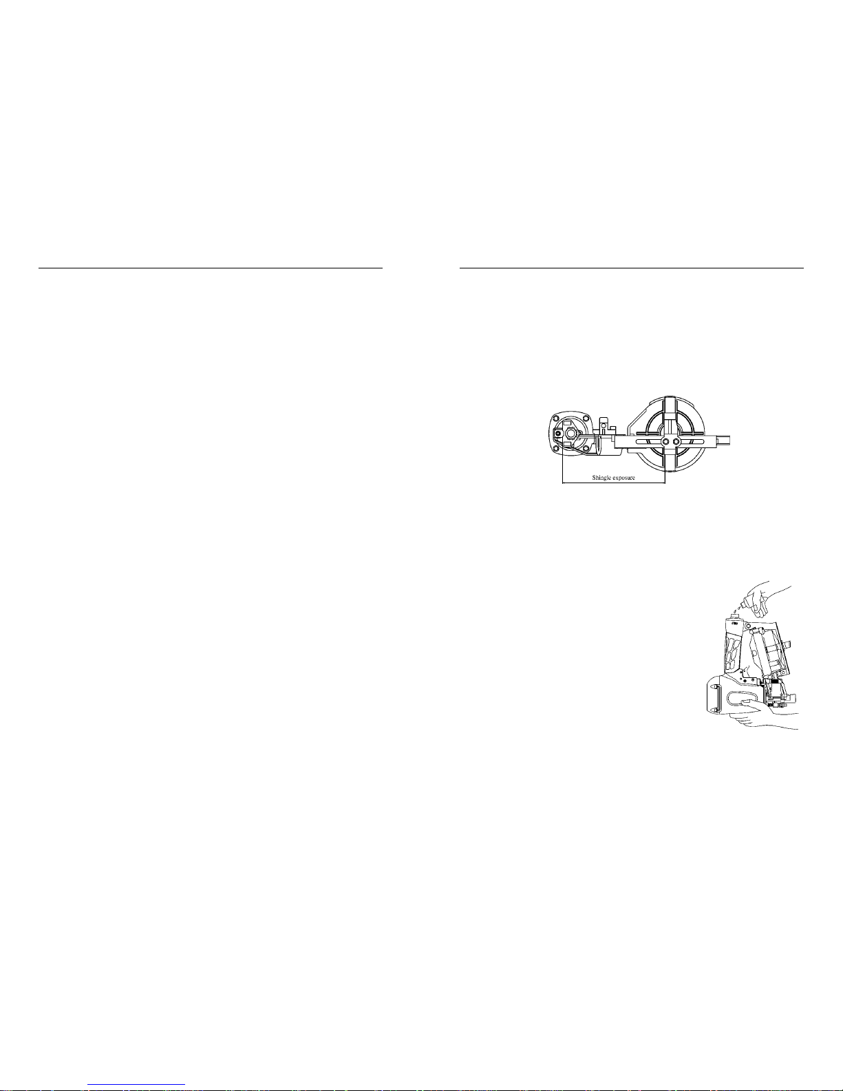
Lubrication
Disconnect tool from the air supply and remove all
fasteners. Apply 3 - 5 drops of air tool oil (provided) in the air inlet two - three times a day. If
the tool will be used outside in the winter, use a
winter grade air tool oil to help keep frost from
forming inside the tool. Do not use other types of
lubricants on this tool, as other lubricants may
contain chemicals harmful to o-rings and other
tool components. Drain compressor tanks and
hoses daily.
Cleaning
Disconnect tool from the air supply and remove all fasteners. Brush tool
off using a parts cleaning brush or clean rag. Open feed pawl door and
magazine cover, and brush out dirt and debris. Check area around trigger
and workpiece contact, and clean as necessary.
TOOL OPERATION
TRIGGER FIRE METHOD
1. Hold the tool securely using the handgrip. Keep finger off trigger
until tool is in position and you are ready to drive a fastener.
2. Position the nose of the tool on the workpiece, placing the nose at
the desired fastener driving position.
3. Press the tool down firmly against the work surface, fully depressing
the workpiece contact (SAFETY).
4. Squeeze the trigger once and release to drive a fastener.
5. Lift the tool off the work surface to reset the workpiece contact.
6. Check fastener for flush drive, and turn nail depth adjustment dial to
obtain desired fastener drive.
7. Increase air pressure to drive deeper or to drive into harder materials.
Reduce air pressure to reduce drive or to drive into softer materials.
For longest tool and part life, always use the lowest air pressure
necessary to drive fasteners to desired depth.
8. Position the tool for driving the next fastener, and repeat the above
procedure. Always keep hands and other body parts away from
areas being fastened.
CONTACT TRIP (BUMP FIRE) DRIVING METHOD
1. Position the nose of the tool over the work surface, near the area
where the first fastener/cap is to be driven.
2. Squeeze and hold the trigger in the depressed position.
3. Bump the workpiece contact (safety) against the work surface at
each point where a fastener is to be driven.
4. Using a bouncing motion, continue moving the tool into position for
each fastener drive.
5. When fastening is completed, release the trigger.
OPERATION
TOOL OPERATION
SHINGLE GUIDE ADJUSTMENT
1. Loosen the screw holding the guide, and reposition the guide to
provided the desired shingle exposure. Tighten screws securely.
2. Place the front edge of the shingle guide against the bottom edge of
the lower course of shingles, and use the front of the safety bracket
to position the edge for the next course of shingles.
Page 8
1514
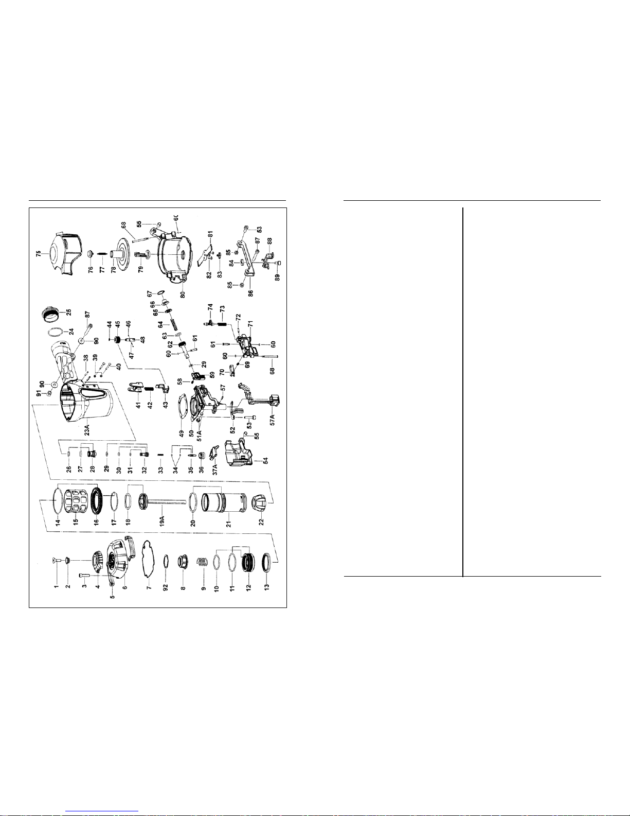
PARTS LISTPARTS SCHEMATIC
ITEM P/N DESCRIPTION
1 GRTN2040 Hex. Soc. Hd. Bolt
2 GRTN1150 Bushing, Deflector
3 GRTN1990 Hex. Soc. Hd. Bolt
4 GRTN1160 Deflector, Exhaust
5 GRTN590 Guide Cover
6 GRTN3010 Cap, Machined
7 GRTN550 Gasket, Cap
8 GRTN560 Piston Stopper
9 GRTN710 Spring
10 GRTN2450 O-Ring
11 GRTN2300 O-Ring
12 GRTN570 Piston, Head Valve
13 GRTN600 Seal
14 GRTN2310 O-Ring
15 GRTN580 Cylinder Seal
16 GRTN610 Cylinder Spacer
17 GRTN2320 O-Ring
18 GRTN2360 O-Ring
19A GRTN1190 Driver Assembly
20 GRTN2200 O-Ring
21 GRTN1180 Cylinder
22 GRTN620 Bumper
23A GRTN2940 Body Assembly
24 GRTN2290 O-Ring
25 GRTN2980 End Cap
26 GRTN2220 O-Ring
27 GRTN2240 O-Ring
28 GRTN630 Valve
29 GRTN2170 O-Ring
30 GRTN2130 O-Ring
31 GRTN2100 O-Ring
32 GRTN640 Valve Plunger
33 GRTN830 Spring
34 GRTN2230 O-Ring
35 GRTN810 Plunger
36 GRTN820 Plunger Cap
37A GRTN650 Trigger Assy Bump.
38 GRTN2540 Spring Pin
39 GRTN2210 Grommet
40 GRTN790 Pin Trigger
41 GRTN1450 Guide, Contact Trip
42 GRTN890 Spring, Safety
43 GRTN1330 Upper Safety Lever
44 GRTN2650 E-Ring
45 GRTN1830 Adjusting Nut
46 GRTN2640 Ball, Steel
ITEM P/N DESCRIPTION
47 GRTN930 Adjusting Spring
48 GRTN1820 Adjusting Post
49 GRTN10 Gasket
50 GRTN1220 Nose
51A GRTN1460 Magnet Bushing Assy.
52 GRTN1350 Guide, Safety Lever
53 GRTN1980 Hex. Soc. Hd. Bolt
54 GRTN1360 Safety Cover
55 GRTN20 Bushing
56 GRTN2510 Spring Pin
57 GRTN1340 L wr. Safety Lever Assy.
58A GRTN1210 Spring
59 GRTN1260 Feed Pawl
60 GRTN2470 O-Ring
61 GRTN1250 Roll Pin
62 GRTN1230 Feed Piston
63 GRTN2180 O-Ring
64 GRTN1810 Feed Spring
65 GRTN1200 Feed Piston Pad
66 GRTN1240 Feed Piston Cover
67 GRTN2720 C-Ring
68 GRTN1310 Shaft Pin Nail Guide
69 GRTN1320 Spring
70 GRTN1270 Nail Stopper
71 GRTN1300 Nail Guide
72 GRTN2500 Spring Pin
73 GRTN1280 Sp ring, Lock Shaft
74 GRTN1290 Lock Shaft
75 GRTN1370 Magazine Cover
76 GRTN30 Tension Post Bush. (Up)
77 GRTN50 Spring
78 GRTN1430 Nail Holder
79 GRTN40 Adjust Post
80 GRTN1380 Magazine
81 GRTN1390 Magazine Guide
82 GRTN2730 Screw
83 GRTN60 Tension Post Bushing
84 GRTN1410 Adjusting Nut
85 GRTN2090 Locknut
86 GRTN1400 Gauge Bracket
87 GRTN2000 Hex. Soc. Hd. Bolt
88 GRTN1420 Adjusting Plate
89 GRTN1940 Hex. Soc. Hd. Bolt
90 GRTN2600 Flat Washer
91 GRTN2740 Locknut
92 GRTN1170 Top Bumper, Washer
A GRDAK400 Driver Maintenance Kit
B GRRBK400 O-Ring Maintenance Kit
C GRTCR175MAN Operator’s Manual
C GRTCR175CASE Tool Case
Page 9
1716
TROUBLESHOOTING
TOOL TROUBLESHOOTING
Your pneumatic fastening tool has been designed for long life and troublefree operation. However, if operating problems arise, please use the
troubleshooting information below to determine how to remedy the problem.
TROUBLESHOOTING
FASTENER DRIVING PROBLEMS
Always disconnect tool from air supply before performing any service on
tool. Correcting a problem while the tool is pressurized may result in
injury from fastener discharge or tool operation.
DANGER
Tool leaks air.
Check for source of leak, and tighten fittings
and screws as required. Discontinue using
tool if air leaks at trigger area or from cap
exhaust. Contact your dealer.
Tool operates, but no
fastener is driven.
Tool won’t operate - nail
jammed in tool nose,
preventing tool from
operating.
Depress magazine release, and open magazine. Remove jammed fastener. Check
magazine for obstructions, debris, and loose
fasteners. Discard loose fasteners. Check
tray setting for correct nail size. Reload nails.
Check coil for broken collation wires. Cut off
broken section and discard. Check tray setting
for correct nail size. Reload nails.
Fasteners do not drive
completely.
AT COMPRESSOR: Increase air pressure.
Do not exceed 120 psi/8.3 bar
Fasteners do not drive
completely when
driving in quick succession.
Inadequate air flow. Use larger diameter hose.
Use compressor with larger storage tank.
Keep hose lines short. Check air hose for
kinks or other restrictions.
Fasteners drive too
deeply.
AT COMPRESSOR: Reduce air pressure.
(Do not reduce below 70 psi/4.8 bar.)
PROBLEM CORRECTIVE ACTION
Fasteners do not drive
completely after air
pressure is increased.
Driver blade worn or broken. See dealer for
replacement.
FASTENER DRIVING PROBLEMS
AT TOOL: Turn adjustment dial to increase
nail drive depth. Add 2 - 3 drops of air tool oil
to inlet.
AT TOOL: Turn adjustment dial to decrease
nail drive depth.
TOOL CHECKS
Keep your nailer in top working condition by checking it daily. See your
Grip-Rite™ dealer for service if part or operating problems are found. Never
use a malfunctioning tool - it could result in serious injury.
Workpiece Contact & Trigger
Check workpiece contact for proper operation before each use. Workpiece
contact must move freely and return to extended position when lifted from
workpiece. Trigger must operate freely.
Daily Inspection
• Check for broken, damaged, or excessively worn parts, and repair
or replace as needed.
• Check for air leaks at trigger, cap, and nose. Disconnect tool from
air supply immediately if leaks are present, and see dealer for
service.
• Make sure all screws are tightened securely.
Page 10

1918
PNEUMATIC TOOL/COMPRESSOR WARRANTY
Pneumatic nailers, staplers & compressors marketed under the
GRIP RITETM brand are warranted to be free from defects in work-
manship & materials (except rubber o-rings, bumpers, seals, driver
blades, dipsticks, & air filters) for a period of one year from the date
of original purchase.
This warranty will not apply when:
• The original receipt (or copy of the original receipt), showing the
original purchase date, is not provided with tools/compressors sent
in for warranty repair
• The tool/compressor has been misused, abused or improperly
maintained
• Alterations have been made to the original tool/compressor
• Repairs have been attempted/made to the original tool/compressor
by any entity other than a proprietary PRIMESOURCE® service/
warranty center or authorized service/warranty center
• Non- GRIP-RITE TOOLS
TM
/ GRIP-RITE COMPRESSORS
TM /
parts
have been used
• The tool has suffered any physical damage due to the use of nonPRIMESOURCE® approved fasteners*
• Repairs are required due to normal wear & tear
• The tool/compressor has been inadequately packaged leading to
damage in-transit to the service/warranty center.
*Approved fasteners include the following brands GRIP-RITE
FAS’NERSTM, FAS’NERS UNLIMITED
TM
IN NO EVENT SHALL PRIMESOURCE® BE LIABLE FOR ANY INDIRECT,
ACCIDENTAL OR CONSEQUENTIAL DAMAGE FROM THE SALE OR
USE OF THESE PRODUCTS. THIS DISCLAIMER APPLIES BOTH
DURING & AFTER THE TERM OF WARRANTY.
THIS IS OUR WARRANTY & IS EXPRESSLY IN LIEU OF ALL OTHER
WARRANTIES, EXPRESS OR IMPLIED, INCLUDING THE WARRANTIES
OF MERCHANTABILITY AND FITNESS FOR A PARTICULAR PURPOSE
(EXCEPT AS MAY BE OTHERWISE PROVIDED BY LAW).
THIS LIMITED WARRANTY GIVES YOU SPECIFIC LEGAL RIGHTS, AND
YOU MAY ALSO HAVE OTHER RIGHTS, WHICH VARY, FROM STATE TO
STATE.
WARRANTY
PNEUMATIC TOOL/COMPRESSOR SERVICE INFORMATION
Should any mechanical problems develop during the life of your
equipment the following options are available for service and parts:
• Call (800)676-7777 where you will be routed to the nearest
PRIMESOURCE® distribution center and directed to the nearest
authorized service/warranty center.
• Logging on to our website at www.primesourcebp.com where
you will find a list of our authorized service centers.
• Contact the PRIMESOURCE® Factory Warranty Center directly
at Phone: (800)207-9259 or Fax: (800)207-9614
STEPS TO TAKE WHEN SHIPPING TOOLS
• Adequately package the product to avoid damage in-transit (in
the case of pneumatic tools, the original blow mold plastic
carrying case is considered adequate packaging).
• Provide the original/copy of receipt showing the original purchase
date.
• Insure your shipment with the shipping company.
PRIMESOURCE® will not be responsible for any tool/compressor
that is lost or damaged by the shipper on route to the
PRIMESOURCE® service/warranty center.
WARRANTY
Page 11
20
USE GENUINE GRIP-RITE®
FASTENERS FOR BEST
PERFORMANCE
GRTCR175MAN
www.grip-rite.com
 Loading...