

Grin Technologies C4820-GR, C4835-GR, C7240-GR, C4820, C4835 User Manual
...
The SineWave Grinfineon
Motor Controller
User Manual - Rev 2.1
Grin Technologies Ltd
Vancouver, BC, Canada
ph: (604) 569-0902
email: info@ebikes.ca
web: http://www.ebikes.ca
Copyright © 2017

SINEWAVE GRINFINEON CONTROLLER MANUAL
Rev 2.1
-2-
Table of Contents
1 Introduction............................................................. 3
1.1 Key Features ................................................................................... 3
2 Installation and Hookup......................................... 4
2.1 Basic Hookup .................................................................................. 4
2.2 Cycle Analyst Hookup.................................................................... 7
2.3 Sensored vs. Sensorless................................................................... 9
2.4 Hall / Phase Mapping Procedure................................................... 9
3 Core Features........................................................ 11
3.1 Silent Sine Wave Mode................................................................. 11
3.2 LED Indicator............................................................................... 11
3.3 On/Off Switch ............................................................................... 12
3.4 Regenerative Braking via Ebrake ............................................... 12
3.5 Proportional Regen via 0-0.8V Throttle Signal.......................... 13
3.6 Fwd / Rev....................................................................................... 14
3.7 Fault Tolerant Hall....................................................................... 15
4 Limitations............................................................. 15
4.1 eRPM Sensorless & Sensored...................................................... 15
4.2 Power Oscillations at Full Throttle when Sensored .................. 16
4.3 60 Degree Hall Timing ................................................................. 17
4.4 No Change to Internal Settings ................................................... 17
4.5 Max Regen Voltage....................................................................... 17
4.6 Won't Show CA Accessory Current Draw................................. 18
5 Specifications......................................................... 19
5.1 Electrical........................................................................................ 19
5.2 Mechanical .................................................................................... 19
5.3 Connector Pinout.......................................................................... 19
SINEWAVE GRINFINEON CONTROLLER MANUAL
Rev 2.1
-3-
1 Introduction
The Grinfineon SineWave controller is based around the popular Xie Chang
device with the XCKJ3232C control chip, but with custom firmware to allow both
sensored and sensorless operation and proportional regenerative braking. The
generous cable harness lengths and crimpable connector standards make it
broadly useful in aftermarket and DIY ebike applications for just about any
geared or direct-drive brushless motor in the 500-3000 watt power range.
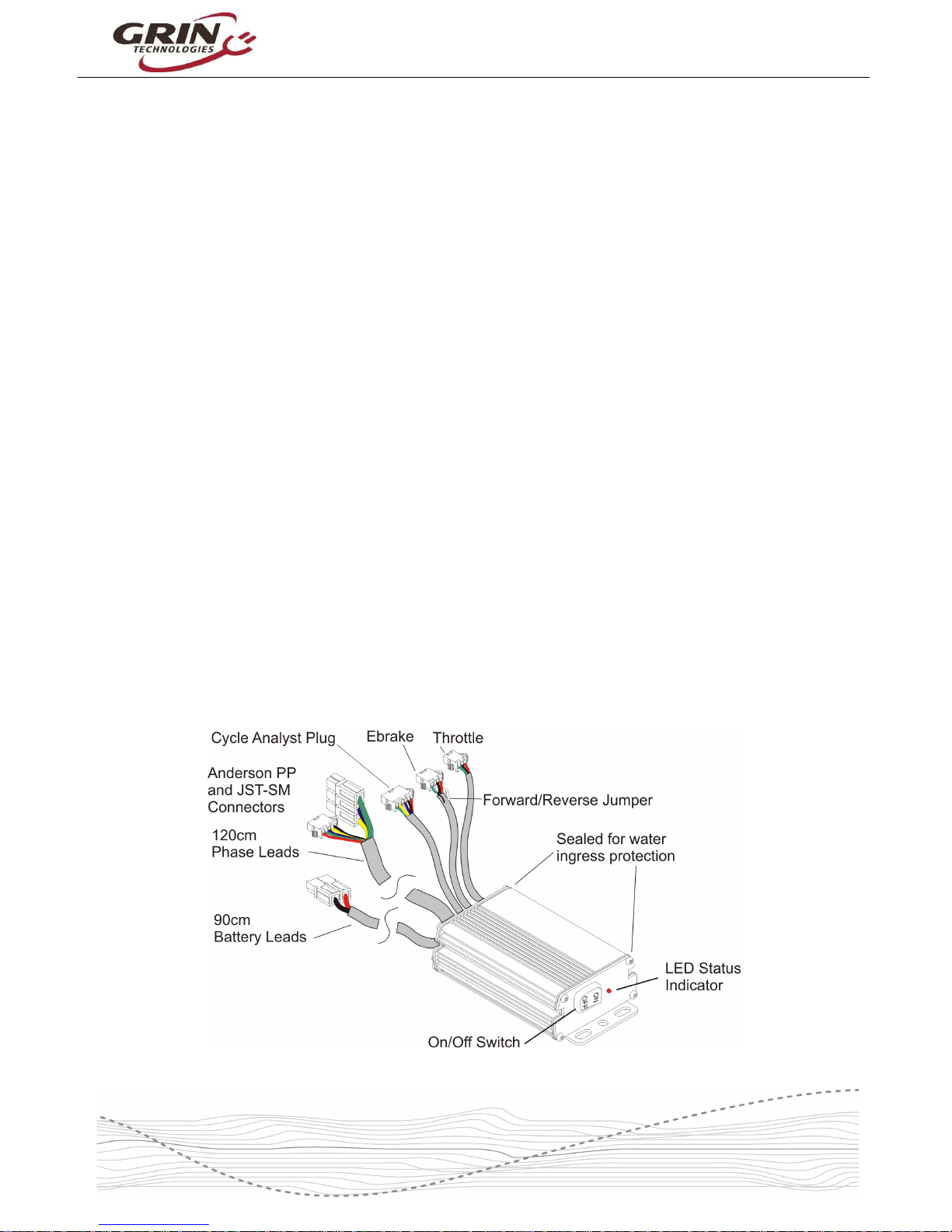
1.1 Key Features
Here are some of the features that make this controller stand out which you won’t
usually find with most 3rd party ebike motor controllers
• Long phase leads (120cm)
• On/Off Switch
• Proportional Regenerative Braking
• Dual Mode, works With and Without Hall Sensors
• Silent Sine Wave Operation in Sensored Mode
• High Sensorless eRPM Compatible with Geared Motors
• Fwd/Rev Input
• LED Status Indicator
• Watertight Enclosure
• Direct Cycle Analyst Plug
• User Crimpable Connectors (JST-SM and Anderson Powerpoles)
Figure 1: Key Controller Hardware Features
SINEWAVE GRINFINEON CONTROLLER MANUAL
Rev 2.1
-4-
2 Installation and Hookup
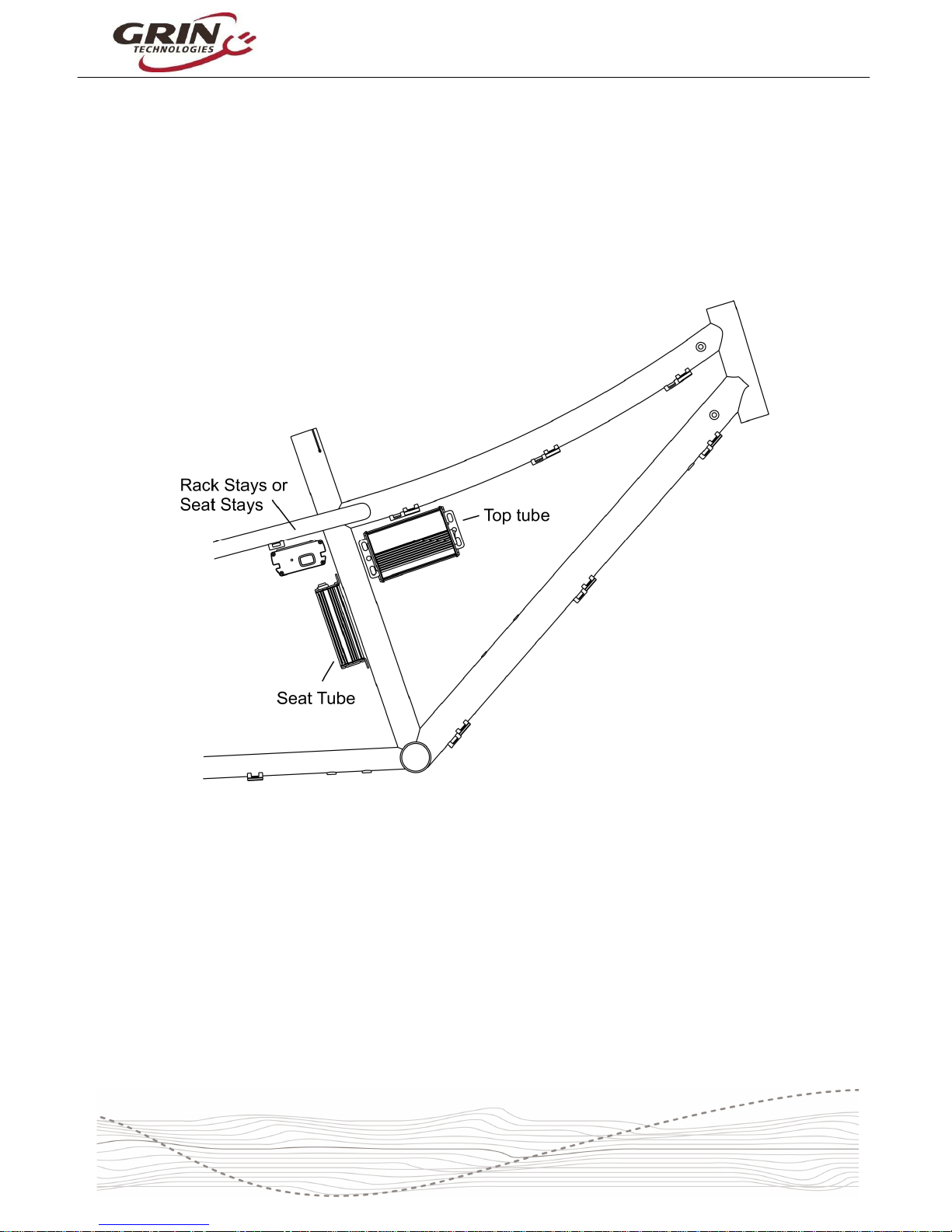
The motor controller end plates have a flange with holes to facilitate securing to
the vehicle. We recommend locating it in place where the ON/OFF switch is
accessible and where it still has good exposure to air flow. Common bicycle
locations include on the front of the rear rack support, between the seat tube and
the rear wheel, or on the top tube with front motors.
Figure 2: Common mounting locations and orientations
Although it is tempting, we do not recommend putting the controller inside a bag
or enclosure box that blocks exposure to air flow, as it will be more susceptible to
overheating. The silicone grommets on the controller end plates do an excellent
job of keeping water out, so there is little concern about having the controller
exposed to the elements, and the orientation of the installed controller does not
matter.
2.1 Basic Hookup
The controller has 6 cables coming out of it: Battery, Motor Phase, Motor Hall,
Throttle, Ebrake, and Cycle Analyst. At the bare minimum, the controller just
needs a throttle, battery pack, and motor connection in order to work:

SINEWAVE GRINFINEON CONTROLLER MANUAL
Rev 2.1
-5-
Figure 3: Basic hookup diagram (motor, throttle, and battery)
The throttle is a 3-pin JST-SM plug intended for Hall Effect throttle devices. It
supplies 4.3V to power the throttle plug and expects a signal of 0.9V - 3.6V as
the throttle is twisted. Throttle signal voltages higher than 4.0V are considered a
fault condition, so if a potentiometer based throttle is used then appropriate
resistors are needed to keep the voltage swing within range.
Figure 4: Controller Throttle Pinout
SINEWAVE GRINFINEON CONTROLLER MANUAL
Rev 2.1
-6-
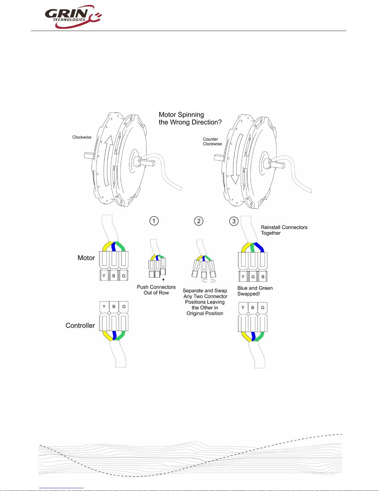
The brushless hub motor will have 3 phase wires that need to terminate with the
3 controller wires. Typically these are green, yellow, and blue, but many other
possibilities exist. If you are running the motor sensorless, then it is only these 3
wires you need to connect and the color pairing does not really matter. If the
motor spins backwards, then simply swap any pair of wires to reverse it.
Figure 5: Example of Motor Direction Change by Swapping Phase Wires
If you want regenerative braking in a basic setup, then you can connect either an
ebrake cutoff lever or other momentary push switch to the 4-pin ebrake plug.
 Loading...