

Page 1
G-FIRE Figure 579
Grooved Rigid Coupling
2 Inch to 8 Inch (DN50 to DN200)
Worldwide
Contacts
www.tyco-fire.com
General
Description
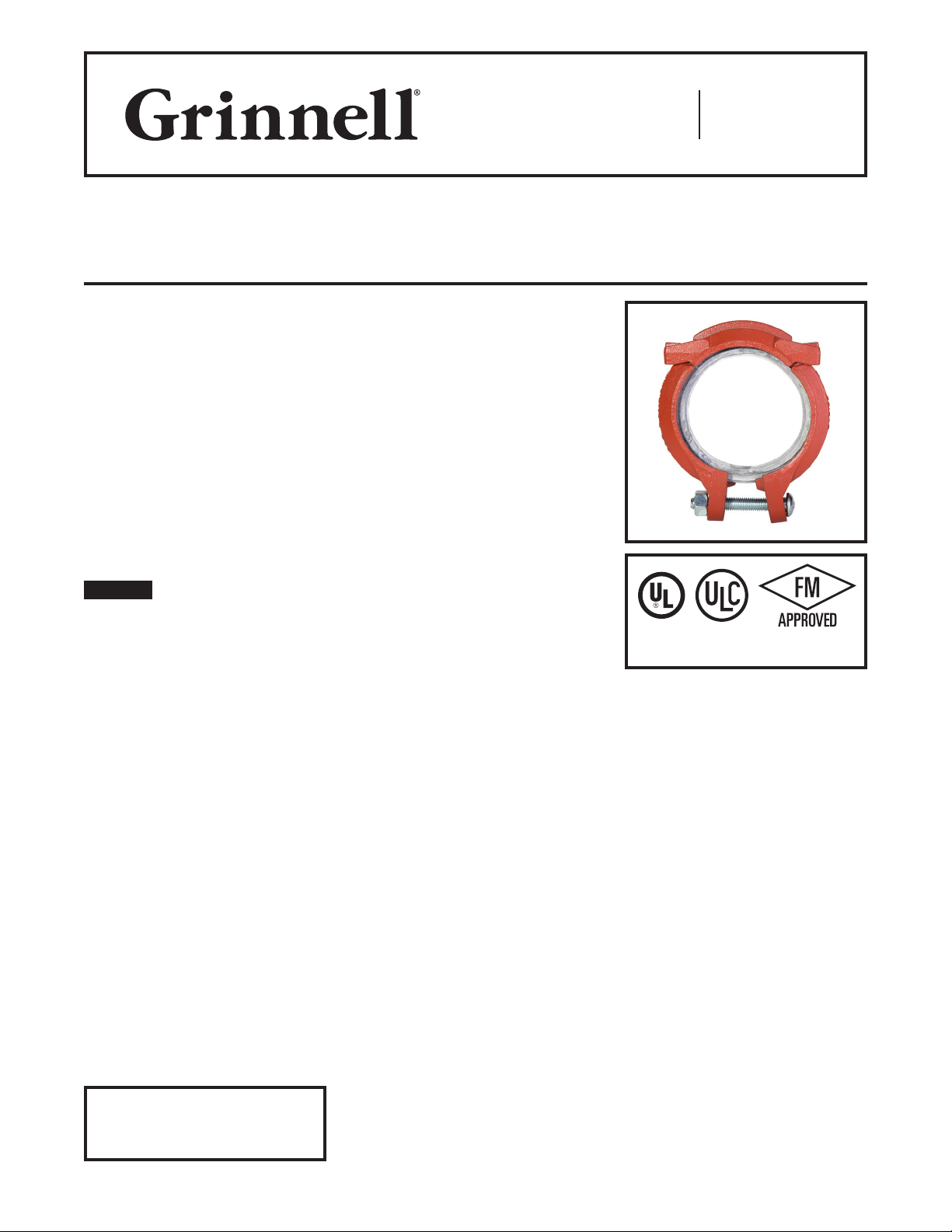
The GRINNELL G-FIRE Figure 579
Grooved Rigid Couplings provide a
rigid joint by firmly gripping along the
full circumference of the pipe grooves.
Figure 579 couplings are a dependable
method of joining pipe and are an economical alternative to welding, threading, or using flanges.
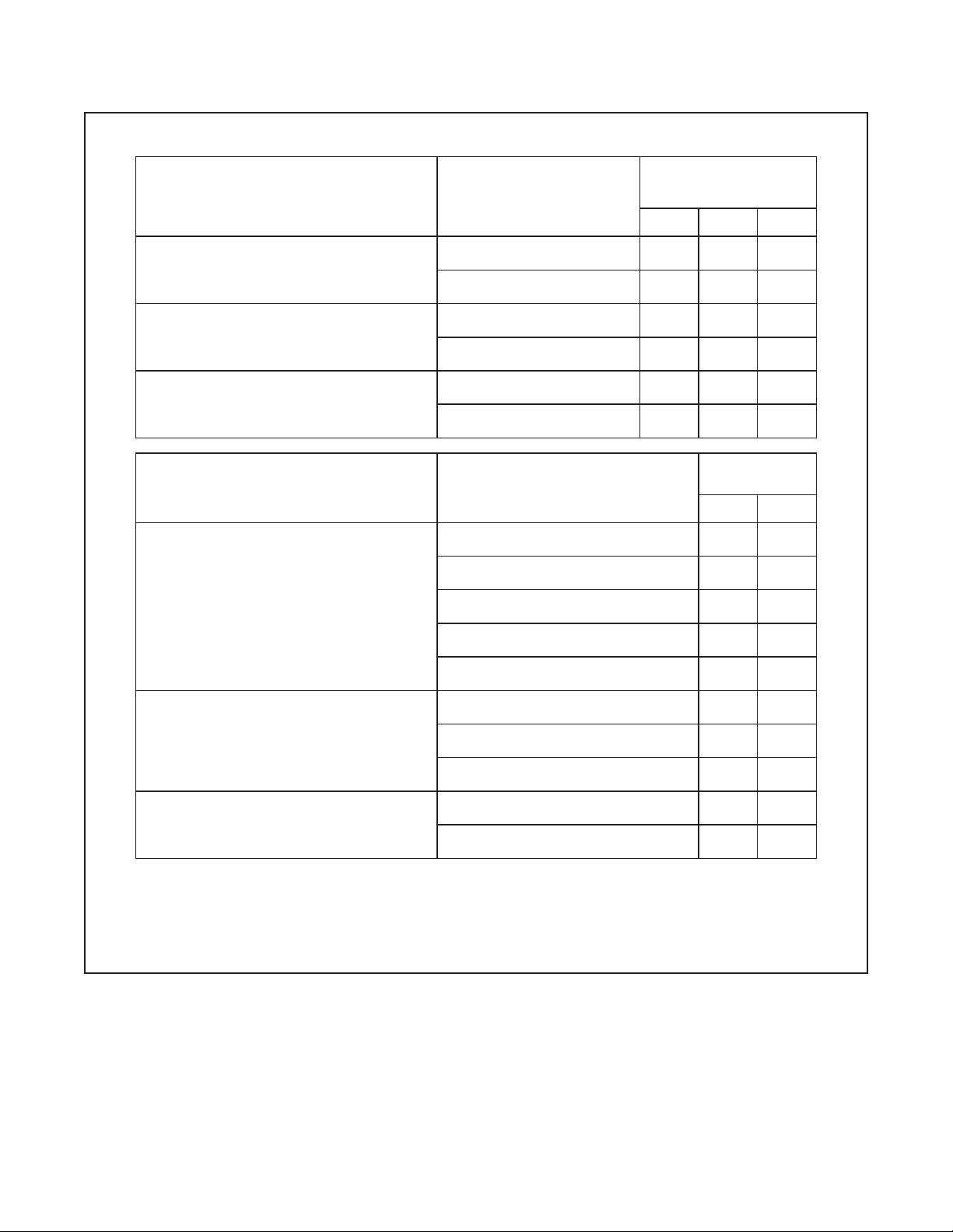
Figure 579 couplings are rated at pressures up to 365 psi (25,2 bar) depending on pipe size and wall thickness
when used in fire protection service
applications. Refer to Table A.
NOTICE
The GRINNELL G-FIRE Figure 579
Grooved Rigid Coupling described
herein must be installed and maintained in compliance with this document, as well as with the applicable
standards of the Approval agency, in
addition to the standards of any other
authorities having jurisdiction. Failure
to do so may result in serious personal
injury or impair the performance of
these devices.
Never remove any piping component
nor correct or modify any piping deficiencies without first de-pressurizing
and draining the system. Failure to do
so may result in serious personal injury,
property damage, and/or impaired
device performance.
It is the designer’s responsibility
to select products suitable for the
intended service and to ensure that
pressure ratings and performance
data are not exceeded. Material and
gasket selection should be verified to
be compatible for the specific application. Always read and understand the
installation instructions.
IMPORTANT
Refer to Technical Data Sheet
TFP2300 for warnings pertaining to
regulatory and health information.
The owner is responsible for maintaining their mechanical system and
devices in proper operating condition. Contact the installing contractor or device manufacturer with any
questions.
Technical
Data
Approvals
UL and ULC Listed
FM Approved
Refer to Table A for details.
Sizes
2 in. to 8 in. (DN50 to DN200)
Housing
Ductile iron conforming to ASTM A536,
Grade 65-45-12
Finish
• Orange non-lead paint
• Red non-lead paint
•
Hot-dipped, Galvanized conforming
to ASTM A153
Bolt/Nut
• ANSI:
Carbon Steel oval neck track head
bolts are heat-treated and conform
to the physical properties of ASTM
A183 Grade 2 and SAE J429 Grade
5 with a minimum tensile strength of
110,000 psi.
Carbon Steel heavy hex nuts conform to the physical properties of
ASTM A183 Grade 2 and SAE J995
Grade 5. Bolts and nuts are zincelectroplated conforming to ASTM
B633.
• Metric:
Carbon Steel oval neck track head
bolts (Gold color coded) are heattreated and conform to the physical
properties of ASTM F568M with a
minimum tensile strength of 760
MPa.
Carbon Steel heavy hex nuts conform to the physical properties of
ASTM A563M Class 9. Bolts and
nuts are zinc-electroplated conforming to ASTM B633.
For Fire Pr otection p ressure r ating,
listin g, and approval informa tion, cont act
your GRINNELL Representative.
Gaskets
• Pre-lubricated Grade “A” EPDM,
Violet color code,
-30°F to 150°F (-34°C to 66°C)
For dry and freezer systems, lubrication is required. Refer to Installation
Manual IH-1000FP for details.
For proper gasket selection, refer to
Technical Data Sheet TFP1895.
Page 1 of 6 FEBRUARY 2019 TFP1856
Page 2
TFP1856
D
OPEN CLOSED
Page 2 of 6
Pipe Size
Nominal
ANSI
Inches
DN
2
50
O.D.
Inches
(mm)
2.375
(60,3)
2 1/2652.875
(73,0)
76 .1
65
80
100
139.7
125
16 5.1
150
150
200
Note:
a. M aximum ava ilable gap between pipe ends. Mi nimum gap = 0.120 in. (3,05 m m)
b. Ma ximum Pre ssure and End Load are tot al from all loads based on standa rd weight ste el pipe.
Pressure ratings and end load s may diffe r for other pi pe materia ls and/or wal l thickne ss. Contact your GRIN NELL Repre sentative.
c. M ax End Gap is for cut grooved standa rd weight pipe.
d. Gold color coded metric bolts and nuts are available upon request.
3.000
(76 ,1)
3
3.500
(88,9)
4
4.500
(114, 3)
5.500
(139,7)
6.500
(165 ,1)
6
6.625
(168 ,3)
8
8.625
(219 ,1)
Max.b
Pressures
psi
(bar)
365
(25,2)
365
(25,2)
350
(24,1)
365
(25,2)
365
(25,2)
300
(20,7 )
300
(20,7 )
365
(25,2)
365
(25,2)
Max.b
End
Load
Lbs.
(kN)
1617
( 7,19 )
2370
(10,54)
2474
(11,0 0 )
3512
(15,62)
5805
(25,82)
7127
(31,70)
9955
(44,28)
12582
(55,97)
21326
(94,86)
Max.
End
Gap
Inches
(mm)
0.32
(8,1)
0.32
(8,1)
0.32
(8,1)
0.32
(8,1)
0.32
(8,1)
0.32
(8,1)
0.32
(8,1)
0.32
(8,1)
0.34
(8,6)
a, c
A
(Open)
Inches
(mm)
3.92
(99,6)
4.48
(113, 8 )
4.53
(115,1)
5.10
(129,5)
6.20
(1 57,5 )
7.63
(193,9)
8.67
(220,2)
8.85
(224,8)
11. 62
(29 5,1)
Nominal Dimensions Coupling Bolts
A
(
Closed
Inches
(mm)
3.41
(86,5)
3.97
(100,7)
4.09
(103,9)
4.57
(116, 0 )
5.67
(143,9)
7.14
(181, 3)
8.14
(206,6)
8.26
(209,8)
10.77
(273,5)
)
(
B
Radius
Inches
(mm)
2.94
(74,7)
3.19
(81,1)
3.24
(82,2)
3.45
(87, 7 )
4.32
(109,7)
4.92
(125,0)
5.39
(1 37,0 )
5.50
(139,6)
7.06
(179,4)
)
(
C
Radius
Inches
(mm)
3.36
(85,2)
3.54
(90,0)
3.59
(91,2)
3.79
(96,2)
4.71
(119, 6)
5.18
(131,5)
5.60
(142,2)
5.65
(143,6)
7. 29
(185 ,2)
)
(
Radius
Inches
(123,3)
(125,2)
(164,9)
D
(mm)
2.40
(60,8)
2.64
(67, 2 )
2.69
(68,3)
3.18
(80,7)
3.70
(93,9)
4.37
(111,1)
4.85
4.93
6.49
)
E
Inches
(mm)
2.05
(51,9)
2.05
(51,9)
2.05
(51,9)
2.05
(51,9)
2.05
(51,9)
2.05
(51,9)
2.05
(51,9)
2.05
(51,9)
2.59
(65,8)
Qty.
1
1
1
1
1
1
1
1
1
Sized
Inches
(mm)
3/8 x 2-3/4
(M10 x 70)
3/8 x 2 3/4
(M10 x 70)
3/8 x 2 3/4
(M10 x 70)
3/8 x 2 3/4
(M10 x 70)
1/2 x 3 1/2
(M12 x 89)
1/2 x 3 1/2
(M12 x 89)
1/2 x 3 1/2
(M12 x 89)
1/2 x 3 1/2
(M12 x 89)
5/8 x 4 1/8
(M16 x 105)
Approx.
Weight
Lbs.
(kg)
1.9
(0,9)
2.1
(1,0 )
2.2
(1,0 )
2.8
(1,3)
4.0
(1,8)
5.9
(2,7)
6.7
(3,0)
6.7
(3,0)
14. 2
(6,4)
A
E
B
C
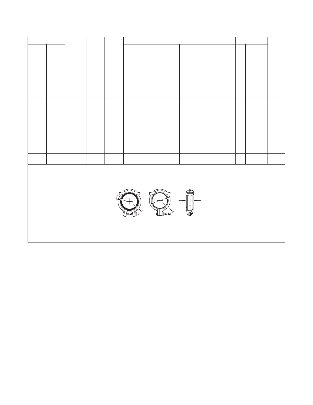
FIGURE 1
G-FIRE FIGURE 579 GROOVED RIGID COUPLING, 2 INCH TO 8 INCH (DN50 TO DN200)
NOMINAL DIMENSIONS
Page 3
Pipe Sizesc
Nominal ANSI Inches
(O.D. mm)
2 (60,3)
2-1/2 (73,0); 3 (88,9); 4 (114,3)
6 (168,3); 8 (219,1)
a
Pipe O.D.c
mm
76 ,1
ISO 4200 Type D, E, and F
139,7
16 5,1
Note:
a. Fo r 8 in. (219,1 mm) size, minimum allowed pip e wall thickn ess is 0.188 in. (4,77 mm).
b. Se e Agency web site for Lis ting/Appr ovals of spec ialty pipe:
UL websi te - see Onlin e Certi cation Dir ectory, ww w.ul.com
FM Global website - www.approvalguide.com
c. A ll couplin gs approve d for dry pip e systems
TABLE A
LISTED/APPROVED PRESSURE RATINGS
Pressure Rating
Pipe
Schedule
b
UL ULC FM
10
40
10
40
10
40
Pipe
Specification
b
365
(25,2)
365
(25,2)
350
(24,1)
365
(25,2)
300
(20,7 )
365
(25,2)
ISO 4200 Type F
ISO 4200 Type E
ISO 4200 Type D
EN 10255 Heavy —
EN 10255 Medium
EN 10255 Heavy —
EN 10255 Medium —
EN 10255 Heavy —
EN 10255 Medium
TFP1856
Page 3 of 6
psi
(bar)
365
(25,2)
365
(25,2)
350
(24,1)
365
(25,2)
300
(20,7 )
365
(25,2)
Pressure Rating
UL FM
300
(20,7 )
300
(20,7 )
300
(20,7 )
300
(20,7 )
300
(20,7 )
300
(20,7 )
365
(25,2)
365
(25,2)
365
(25,2)
365
(25,2)
300
(20,7 )
365
(25,2)
psi
(bar)
350
(24,1)
300
(20,7 )
—
300
(20,7 )
300
(20,7 )
300
(20,7 )
300
(20,7 )
300
(20,7 )
300
(20,7 )
300
(20,7 )
Page 4
TFP1856
Page 4 of 6
Installation
GRINNELL G-FIRE Figure 579 Grooved
Rigid Coupling must be installed in
accordance with this section.
General Instructions
Always read and understand the
instructions. Never remove any piping
component without verifying that the
system is depressurized and drained.
The Figure 579 Grooved Rigid Coupling with additional lubrication is recommended for applications below
40°F (4°C).
The installation is based on pipe
grooved in accordance with Standard
Cut Groove or Roll Groove Specifications. Refer to Technical Data Sheet
TFP1898 for additional information.
Step 1.
Step 2.
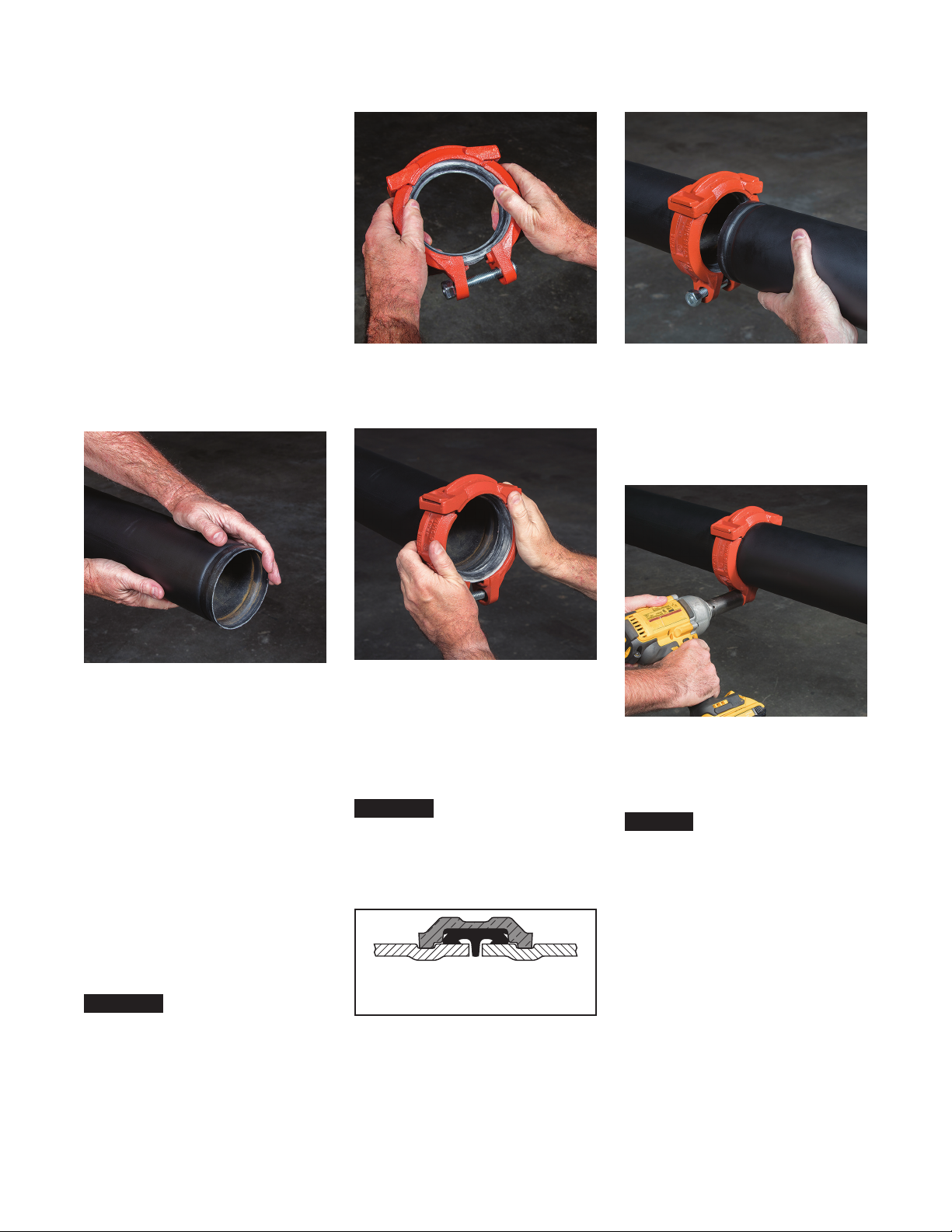
Step 2. Do not remove the nut from the
bolt. Open the coupling by extending
the coupling segments out to the extent
allowed by the bolt and nut.
Step 3.
Step 4.
Step 4. Slide the other pipe end into
the gasket/coupling ensuring that it
makes contact with the center stop of
the gasket (Ref. Figure 2). Both pipes
should be aligned vertically and horizontally. Verify that the housing is over
the gasket and that the housing keys
are aligned with the pipe grooves.
Step 5.
Step 1. Inspect exterior groove and
ends of the pipe to verify all burrs,
loose debris, dirt, chips, paint and any
other foreign material such as grease
are removed. Pipe end sealing surfaces must be free from sharp edges,
projections, indentations, and/or other
defects.
Grade “A” gaskets are supplied with a
pre-lubricant and do not require additional lubrication for applications above
40°F (4°C).
NOTE: Additional lubrication must be
used in dry pipe and freezer applications. A silicone based lubricant is
recommended.
To prevent deterioration of the gasket
material a petroleum lubricant should
not be used on Grade “A” “EPDM”.
CAUTION
Removal of the nut from the bolt may
result in the coupling segments separating at the hinges and the coupling
disengaging from the pipe. Use caution
to avoid equipment damage and/or
personal injury.
Step 3. Push the gasket/coupling onto
one end of the pipe until the centerstop of the gasket is in contact with the
end of the pipe (Ref. Figure 2).
NOTE: The gasket center-stop should
not ride up onto the gasket sealing
surface (Ref. Figure 2).
CAUTION
Do not leave coupling unattended on
a single pipe end as it may disengage
from the pipe. Failure to do so may
result in equipment damage and/or
personal injury.
FIGURE 2
FIGURE 579 CENTER-STOP
GASKET POSITION
Step 5. Tighten nut to the recommended bolt torque (Ref. Table B).
Visually inspect the coupling to ensure
that the housing keys are engaged into
the pipe grooves.
NOTICE
The 2 in. to 8 in. (DN50 to DN200) couplings have an intended gap of up to
1/16 in. (1,60 mm) at the bolt pad to
allow for positive rigid gripping onto
the pipe.
Bolt-torque information is supplied
as a guideline and may be used when
setting the torque on power impact
wrenches. Refer to the manufacturer’s
instructions for settings.
Bolt lengthens require the use of deep
or extra-deep-well sockets. Sockets
inner depth information is supplied for
reference only. (Ref. Figure 4) For specific socket recommendations, contact
Technical Services.
Page 5
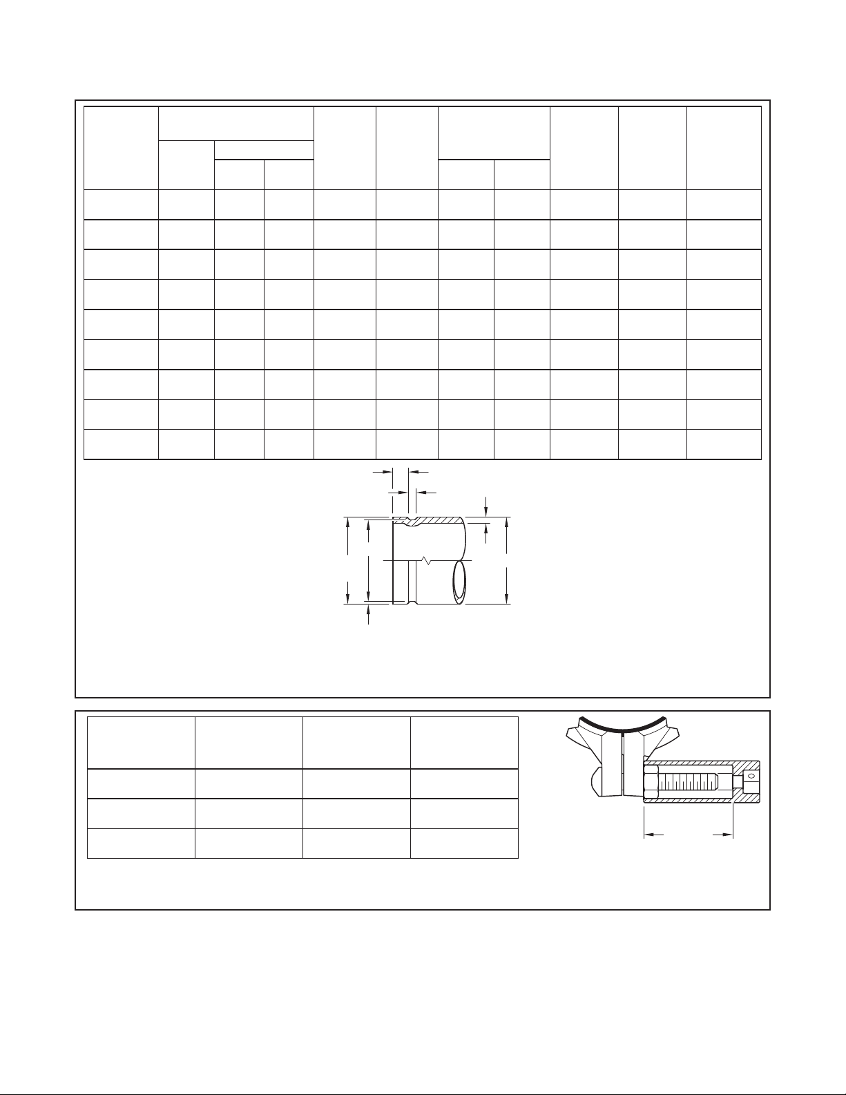
TFP1856
A
D
OD
FLARE
DEPTH
Page 5 of 6
Nominal
Pipe Size
ANSI
Inches
DN
2
50
2-1/ 2
65
76 ,1m m
(65)
3
80
4
100
139,7mm
(125)
16 5,1mm
(150 )
6
150
8
200
O.D.
Inches
(mm)
2.375
(60,3)
2.875
(73,0)
3.000
(76,2)
3.500
(88,9)
4.500
(114, 3)
5.500
(139,7)
6.500
(165 ,1)
6.625
(168 ,3)
8.625
(219 ,1)
Pipe O.D.
Inches (mm)
Tolerance
+ - Actual
0.024
(0,61)
0.029
(0,74)
0.030
(0,76)
0.035
(0,89)
0.045
(1,14)
0.056
(1,4 2)
0.063
(1,6 0)
0.063
(1,6 0)
0.063
(1,6 0)
0.024
(0,61)
0.029
(0,74)
0.030
(0,76)
0.031
(0,79)
0.031
(0,79)
0.031
(0,79)
0.031
(0,79)
0.031
(0,79)
0.031
(0,79)
A
±
0.030
±
0.76mm
Inches
(mm)
0.625
(15, 88)
0.625
(15, 88)
0.625
(15, 88)
0.625
(15, 88)
0.625
(15, 88)
0.625
(15, 88)
0.625
(15, 88)
0.625
(15, 88)
0.750
(19,05)
±
0.030
±
0.76mm
Inches
(mm)
0.344
(8 ,74)
0.344
(8 ,74)
0.344
(8 ,74)
0.344
(8 ,74)
0.344
(8 ,74)
0.344
(8 ,74)
0.344
(8 ,74)
0.344
(8 ,74)
0.469
(11,9 1)
B
C
Groove
Diameter
Inches/mm
Tol.
+0.000
2.250
(57,1 5)
2.720
(69,09)
2.845
(72,26)
3.344
(84,94)
4.334
(110, 0 8)
5.334
(135,48)
6.330
(160,78)
6.455
(163,96)
8. 441
(214,40)
B
-0 .015
(-0,38)
-0 .018
(-0,46)
-0 .018
(-0,46)
-0 .018
(-0,46)
-0.020
(-0,51)
-0.022
(-0,56)
-0.022
(-0,56)
-0.022
(-0,56)
-0.025
(-0,64)
T
D
Nominal
Groove
Depth
Inches
(mm)
0.062
(1,6 0)
0.078
(1,98)
0.076
(1,93)
0.078
(1,98)
0.083
(2,11)
0.083
(2,11)
0.085
(2,16 )
0.085
(2,16 )
0.092
(2,34)
T
Minimum
Wall
Inches
(mm)
0.065
(1,6 5)
0.083
(2,11)
0.083
(2,11)
0.083
(2,11)
0.083
(2,11)
0.109
(2,77 )
0.109
(2,77 )
0.109
(2,77 )
0.109
(2,77 )
Maximum
Allow Flare
Diameter
Inches
(mm)
2.48
(62,99)
2.98
(75,6 9)
3.10
(78 ,74 )
3.60
(91,44 )
4.60
(116, 8 4)
5.60
(142,24)
6.60
(1 67,6 4 )
6.73
(170,94 )
8.80
(223,52)
C
MAX.
*Swage g rooves must b e factor y produce d by Wheatla nd
Tube Co. and me et standa rd roll groove dimensio ns.
Swage grooves are UL Li sted only. See O nline Cer tications Director y at www.UL.c om for details.
FIGURE 3
STANDARD SPECIFICATION
ROLL GROOVE AND SWAGE GROOVE*
STEEL PIPE
Bolt Size
ANSI
Inches
(mm)
3/8
(M10)
1/2
(M12)
5/8
(M16)
Socket Size
ANSI
Inches
(mm)
11/ 16
(17 )
7/8
(22)
1-1/16
(27)
Inner Minimum
Socket Depth
Inches
(mm)
2.00
(51)
2.40
(61)
3.00
(76)
Bolt Torque
Range
lb-ft
(N·m)
30-40
(40- 60)
90-110
(12 0-150 )
130-160
(175-215)
INNER
MINIMUM
SOCKET
FIGURE 4
BOLT TORQUE AND SOCKET SIZE
RECOMMENDATIONS
Page 6
TFP1856
A
D
OD
Page 6 of 6
Nominal
Pipe Size
ANSI
Inches
DN
2
50
2-1/ 2
65
76 ,1m m
(65)
3
80
4
100
139,7mm
(125)
16 5,1mm
(150 )
6
150
8
200
O.D.
Inches
(mm)
2.375
(60,3)
2.875
(73,0)
3.000
(76,2)
3.500
(88,9)
4.500
(114, 3)
5.500
(139,7)
6.500
(165 ,1)
6.625
(168 ,3)
8.625
(219 ,1)
Pipe O.D.
Inches (mm)
Tolerance
+ - Actual
0.024
(0.61)
0.029
(0,74)
0.030
(0,76)
0.035
(0,89)
0.045
(1,14)
0.056
(1,4 2)
0.063
(1,6 0)
0.063
(1,6 0)
0.063
(1,6 0)
0.024
(0.61)
0.029
(0,74)
0.030
(0,76)
0.031
(0,79)
0.031
(0,79)
0.031
(0,79)
0.031
(0,79)
0.031
(0,79)
0.031
(0,79)
A
±
0.030
±
0.76mm
Inches
(mm)
0.625
(15, 88)
0.625
(15, 88)
0.625
(15, 88)
0.625
(15, 88)
0.625
(15, 88)
0.625
(15, 88)
0.625
(15, 88)
0.625
(15, 88)
0.750
(19,05)
±
0.030
±
0.76mm
Inches
(mm)
0.313
( 7,95)
0.313
( 7,95)
0.313
( 7,95)
0.313
( 7,95)
0.375
(9,53)
0.375
(9,53)
0.375
(9,53)
0.375
(9,53)
0.438
(11,13)
B
(110, 0 8)
(135,48)
(160,78)
(163,96)
(214,40)
B
Groove
Diameter
Inches/mm
2.250
(57,1 5)
2.720
(69,09)
2.845
(72,26)
3.344
(84,94)
4.334
5.334
6.330
6.455
8. 441
T
C
Tol.
+0.000
-0 .015
(-0,38)
-0 .018
(-0,46)
-0 .018
(-0,46)
-0 .018
(-0,46)
-0.020
(-0,51)
-0.022
(-0,56)
-0.022
(-0,56)
-0.022
(-0,56)
-0.025
(-0,64)
D
Nominal
Groove
Depth
Inches
(mm)
0.062
(1,6 0)
0.078
(1,98)
0.076
(1,93)
0.078
(1,98)
0.083
(2,11)
0.083
(2,11)
0.085
(2,16 )
0.085
(2,16 )
0.092
(2,34)
T
Minimum
Wall
Inches
(mm)
0.154
(3,91)
0.188
(4,78)
0.188
(4,78)
0.188
(4,78)
0.203
(5,16)
0.203
(5,16)
0.219
(5,56)
0.219
(5,56)
0.238
(6,05)
C
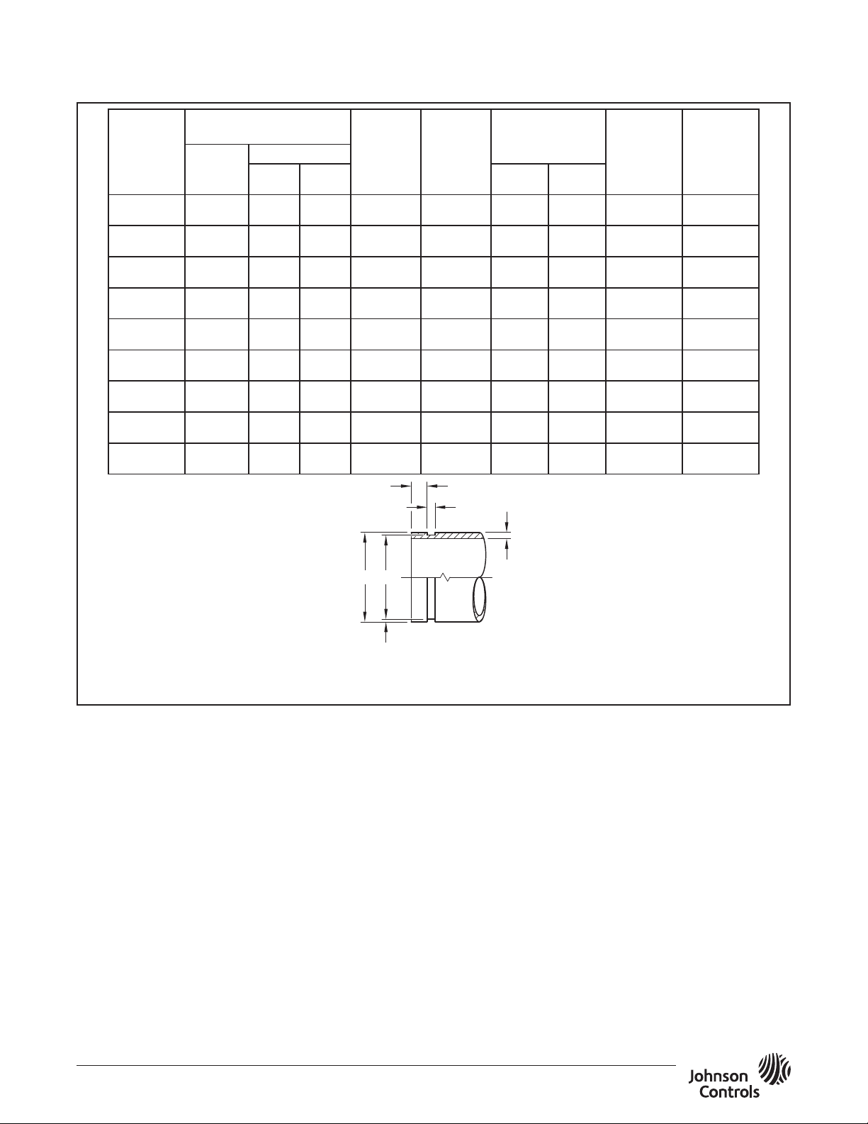
FIGURE 5
STANDARD SPECIFICATION
CUT GROOVE STEEL PIPE
Care and
Maintenance
The GRINNELL G-FIRE Figure 579
Grooved Rigid Coupling must be maintained in accordance with this section.
Before closing a fire protection system
main control valve for maintenance
work on the fire protection system
that it controls, obtain permission to
shut down the affected fire protection
system from the proper authorities
and notify all personnel who may be
affected by this decision.
After placing a fire protection system
in service, notify the proper authorities
and advise those responsible for monitoring proprietary and/or central station
alarms.
The owner is responsible for the inspection, testing, and maintenance of their
fire protection system and devices in
compliance with this document, as well
as with the applicable standards of the
NATIONAL FIRE PROTECTION ASSOCIATION, such as NFPA 25, in addition
to the standards of any authority having
jurisdiction. Contact the installing contractor or product manufacturer with
any questions. Any impairments must
be immediately corrected.
Automatic sprinkler systems are recommended to be inspected, tested,
and maintained by a qualified Inspection Service in accordance with local
requirements and/or national codes.
Limited
Warranty
For warranty terms and conditions, visit
www.tyco-fire.com.
Ordering
Procedure
GRINNELL Products are available globally through a network of distribution
centers. For the nearest distributor, visit
www.tyco-fire.com. When placing an
order, indicate the full product name.
Specify: G-FIRE Figure 579 Grooved
Rigid Coupling, quantity, pipe size
(Nominal ANSI or O.D.), finish (Orange,
Red, or Galvanized), and Pre-lubricated
Grade “A” EPDM gasket.
1400 Pennbroo k Parkway, Lansdale, PA 1944 6 | Telephone +1-215-362 -0700
© 2019 John son Control s. All right s reserved. A ll specifica tions and ot her informa tion shown wer e current as o f document rev ision date an d are subject t o change wit hout notice.
NATIONAL FIRE P ROTECTION ASSOCIATIO N and NFPA are register ed trademarks of N ational Fire Protec tion Associati on
 Loading...