

Worldwide
Marking
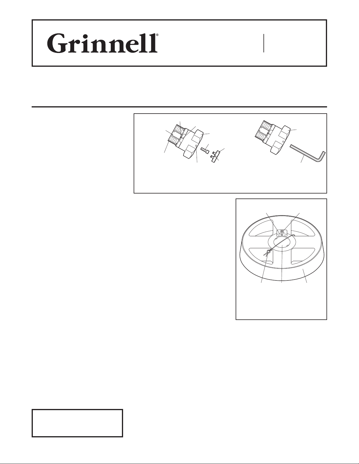
Fine Setting Scale
Cover Plug
Sealing Wire
(Longitudinal Scale)
Basic Setting Scale
Display Display
seal
Grinnell Mechanical Products
Installation / Assembly Instructions,
Model CB800 Circuit Balancing Valve
Contacts
www.grinnell.com
General
Description
GRINNELL CB800 Circuit Balancing
Valves are designed for installation in
hot water heating and chilled water
air conditioning systems and serve to
achieve a hydronic balance between
the various circuits of the system.
These installation instructions are
designed for the Grooved, Flanged,
Threaded, and Soldered type Circuit
Balancing Valves.
General Instructions
Always read and understand the
instructions. Never remove any piping
component without verifying that the
system is depressurized and drained.
It is the designer’s responsibility
to select products suitable for the
intended service and to ensure that
pressure ratings and performance data
are not exceeded.
It is recommended that the valve be
installed in the return line.
Install the valve with the flow in the
same direction as the arrow cast in the
body.
Valve must be installed with a minimum
of 3D (3 x nominal pipe diameter) of
straight pipe in the upstream side.
Valve may be installed in the vertical
or horizontal position, with the handwheel up, down or on the side.
Presetting
The required preset value can be
obtained by referencing the flow chart
for the appropriate size of valve. (See
reference documents on www.grinnell.
com) Following the steps below, adjust
the basic and fine adjustment scale on
the handwheel to match the selected
presetting.
Step 1. The preset value of the valve
is adjusted with the handwheel (Ref.
Figure 1 or 2).
Refer to Technical Data Sheet
G1100 for warnings pertaining to
regulatory and health information.
Page 1 of 2 AUGUST 2018 G988
IMPORTANT
Sliding
Indicator
HANDWHEEL PRESETTING AND REPOSITIONING
Step 2. Turn the handwheel so that the
arrow on the sliding indicator matches
the basic adjustment value. One complete turn of the handwheel adjusts the
indicator one full position.
The fine setting is displayed in the scale
under the handwheel and indicates
1/10th of a turn of the handwheel.
Step 3. With the valve open to the
preset value, use a small screwdriver
and gently pry the cover plug out of the
hand-wheel. Using a 3 mm Allen key for
the 1/2 in. to 2 in., 4 mm Allen key for
the 2-1/2 in. to 6 in., or a 10 mm screwdriver for the 8 in. to 12 in., insert the
tool into the screw (Ref. Figure 1 or 2)
and turn clockwise until tight. This will
lock the hand-wheel so that the valve
can not be opened beyond the preset
value. The hand-wheel may still be
turned to the closed position. Replace
the cover plug.
(Peripheral Scale)
Hole For
1/2 INCH TO 6 INCH
Handwheel
Screw
Hole For
Sealing Wire
FIGURE 1
Repositioning the
Handwheel
Depending on the position of the valve
in the system, it may be desirable to
move the 1/2 in. to 6 in. handwheel and
adjustment scales to make it easier to
read.
Step 1. Ensure the valve is closed and
the adjustment scale is set at 0.
Step 2. Use a small screwdriver and
gently pry the cover plug out of the
hand-wheel.
Handwheel
Allen Wrench
Cover
plug
complete turns
Handwheel
1/10th of a turn
Lead
FIGURE 2
8 INCH TO 12 INCH
HANDWHEEL PRESETTING
AND REPOSITIONING
Step 3. Use a 12 mm socket for the
1/2 in. to 2 in. handwheel and 6mm
Allen key for the 2-1/2 in. to 6 in. handwheel to remove the Allen screw (Ref.
Figure 1).
Step 4. Gently pull the handwheel up
and remove it from the valve spindle.
Step 5. Reposition the handwheel so
that the adjustment scale is visible
and slide the handwheel down on the
spindle.
Step 6. Replace the screw and tighten.
Step 7. Replace the cover plug.

G988
Clip
Guide
Lead
Page 2 of 2
Seal
Reference
Documents
For more details, refer to the Instruction
Handbook IH-4500 and Technical Data
Sheet G450.
PROTECTING AND LOCKING
FIGURE 3
THE HANDWHEEL
Protecting the Setting
A sealing wire may be threaded through
the hole in the handwheel (Ref. Figure
2 or 3) and the lead seal to be fixed to
prevent tampering of the setting.
Locking the Handwheel
Locking 1/2 in. to 6 in.
Handwheel
The hand wheel can be locked in any
position. Slide the enclosed clip into
the cut-out in the hand wheel between
the guides (Ref. Figure 3), making sure
it locates into the sliding indicator.
Attach the lead seal wire through the
hole in the clip then through the hole in
the side of the hand wheel. Ensure the
sealing wire is fitted tightly, then crimp
the seal.
Locking 8 in. to 14 in.
Handwheel
The handwheel can be locked in any
position (1/10th of a turn) by removing
the existing cover plug and replacing it
with a special one. The sealing wire is
fitted through the hole in the handwheel
and a Lead Seal is fitted (Ref. Figure 2).
NOTICE
For presetting and fine adjustment of
the flow volume, use the Grinnell Model
MC2 flow computing hand held Differential Measuring Computer.
1400 Pennbro ok Park way, Lansdale , PA 19446 | Tele phone +1-215-362- 0700
© 2018 John son Control s. All right s reserved. A ll specifica tions and ot her informa tion shown wer e current as o f document rev ision date an d are subject t o change wit hout notice.
 Loading...