

Page 1
1104 Form # AM-324-03
American Metal Ware®Hot Water Boiler
Installation, Operation & Service Manual
For
Models 815, 830, 850
Gas
Electric Steam
Special Features
After completing installation and set-up, the
equipment owner should keep this manual for
future reference.
© Grindmaster Corporation™, 1995
PRINTED IN USA
Grindmaster Corporation™
4003 Collins Lane
Louisville, Kentucky 40245 USA
(502) 425-4776
(800) 695-4500 (USA and Canada only)
(800) 568-5715 (technical service only)
FAX: (502) 425-4664
www.grindmaster.com
X
TABLE OF CONTENTS
General Description.................................1
Installation...............................................1
Thermostat..............................................4
Adjustment..................................4
Service Instructions.................................5
Dual Level Control...................................6
Troubleshooting.......................................7
Solenoid Valve
Safety Instructions.....................11
Installation..................................11
Disassembly..............................12
Assembly...................................12
Troubleshooting.........................12
Cleaning....................................12
Testing.......................................12
Repair Kits.................................12
Coils..........................................12
Parts List...............................................13
Page 2

Page 1 American Metal Ware Hot Water Boiler
Electric Models
815, 830, 850
Equipped with Option 46 Automatic Refill
Option 39 Low Water Cut-Off System
General Description
This unit is a high temperature hot water boiler. It consists of a non-pressure, vented water
compartment into which is installed an electric immersion heater thermostatically controlled through
a contactor relay, to keep the water always at the desired brewing temperature. Automatic refill
maintains water level in water compartment. All control system components are enclosed in a
stainless steel housing on the right end of the urn:
A master ON-OFF switch shuts off entire unit, including heater circuit: Separate low water cutoff
system protects heater and entire unit from damage.
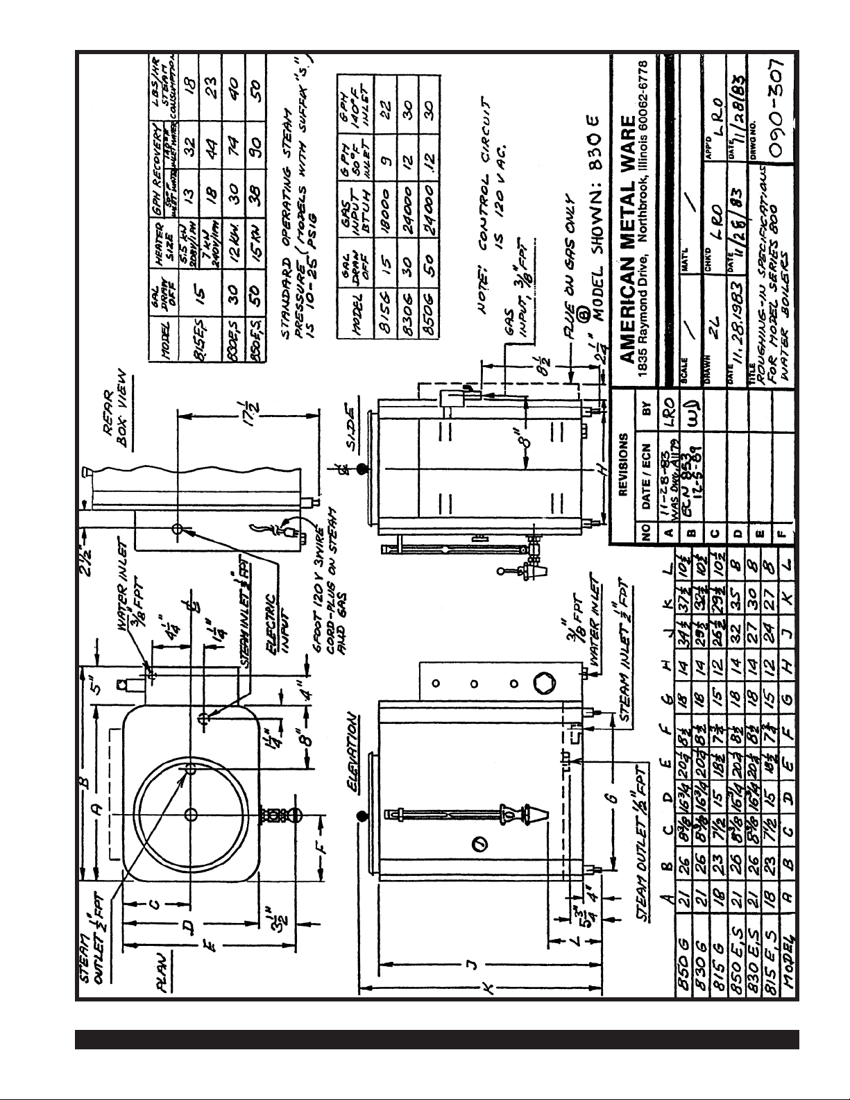
Installation
1.
2.
3.
4.
5.
IMPORTANT TO ALLOW 6" CLEAR SPACE TO RIGHT ON CONTROL BOX FOR
ACCESS. Urn should be level, both front to back and left to right.
CONNECT WATER LINE. 3/8" NPT water inlet located at right end. Provide shutoff valve and
union in supply line near urn. Cold or hot water may be used, but hot water will give greater gallon per hour capacity. We strongly recommend the use of copper or aluminum tubing to provide
flexibility and avoid strain on the unit. 3/8" O.D. Tubing is recommended.
CONNECT URN TO ELECTRIC POWER. Check to be sure that name plate marking of voltage
phase and number of wires matches supply lines. Remove cover on control housing. Terminal
block for line connections located in housing on right end. See drawing, as required. It is recommended that a fused disconnect switch be installed near urn. Urn body must be grounded
either through metallic conduit or else by means of ground wire. An experienced electrician
should be responsible for the installation of the unit, and its associated supply line. NOTE:
Neutral wire required on all single phase and on 208 volt 3 phase power supplies to operate
120volt AC control circuit. Do not replace cover until completion of installation.
FILL WATER COMPARTMENT. Turn on water supply and electric service to urn. Turn master
switch on. Do NOT turn on thermostat until water shows in gauge glass (approximately 6 minutes). When water shows, remove adhesive WARNING label from thermostat knob. Turn
thermostat knob maximum clockwise to BREW position. Pilot light over knob should light
showing heater power on. Water compartment will fill automatically to stop-full level, and should
reach operating temperature approximately 45 minutes later. When the pointer on thermometer
approaches the "W" in the blue BREW zone, unit is ready for operation.
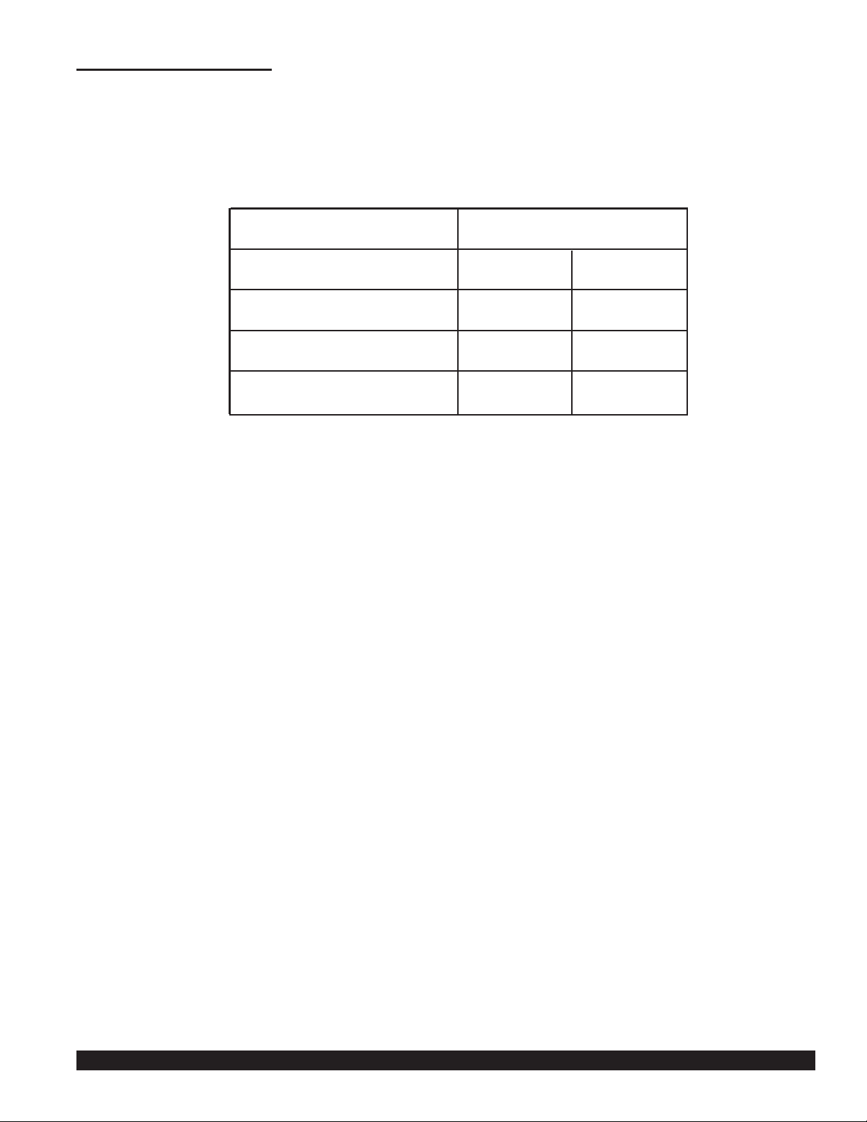
REFILL RATE ADJUSTMENT. To gain maximum capacity of the boiler, and shorten heat
recovery time, adjust the water inlet flow regulator (located inside the control box) according
to the chart provided. Turning the threaded adjustment shaft clockwise increases the flow
rate, counterclockwise will decrease it.
Page 3
American Metal Ware Hot Water Boiler Page 2
TO CHECK REFILL RATE, allow water to fill to stop/full level automatically; then turn off master
switch. Draw off 1 gallon of water from faucet. Turn master switch back on and time how long it
takes for the water level to come up to stop/full mark again. Compare time with chart provided
and adjust accordingly.
Installation (cont.)
5)
*Factory setting
HEATER SIZE
(OR EQUIV. STEAM USE)
5.5KW/208 Volt or
7KW/240 Volt
12KW
15KW
COLD WATER*
CONNECTION
3min. 30sec.
1min. 50 sec.
1min. 25sec.
TIME TO REFILL 1 GALLON
HOT WATER
CONNECTION
1min. 25sec.
45sec.
35sec.
Page 4
Page 3 American Metal Ware Hot Water Boiler
Page 5

American Metal Ware Hot Water Boiler Page 4
Thermostat
Factory set so that knob on BREW setting holds unit at brewing temperature toward HIGH end of
brew zone on thermometer dial. Then, if turned back to HOLD position, thermostat should cycle
on and off and hold at LOW 'end of BREW zone on thermometer.
Thermostat Adjustment
1.
2.
If water temperature is below HIGH end of BREW zone on thermometer dial with knob on
BREW setting, remove knob by pulling straight outward. Using a small screwdriver, insert in
hole in center of shaft, turn slotted screw counter-clockwise until red pilot light goes on.
Check to see that water in unit holds at HIGH end on BREW zone on thermometer and
does not
boil.
If water boils with thermostat knob set at the BREW position, remove knob by pulling
straight outward. Using a small screwdriver, insert into hole in center of shaft, turn slotted
screw clockwise until red pilot light goes out. Hold shaft so it does not turn while adjusting
screw. Add cold water and check that heat comes back on (Pilot light glows), and that thermostat cycles at temperature at HIGH end of BREW zone on thermometer dial.
If thermostat will not cycle, replace entire control.
Page 6

Page 5 American Metal Ware Hot Water Boiler
Service Instructions
PROBLEM: THERMOSTAT DIAL TURNED TO BREW AND WATER IN COMPARTMENT REMAINS COLD
POSSIBLE CAUSE
1.
2.
PROBLEM: WATER BOILS CONTINUOUSLY WITH THERMOSTAT DIAL ON POSITION BREW OR HOLD.
POSSIBLE CAUSE
1.
2.
3.
Set knob on BREW and remove knob by pulling outward. Using
small screwdriver in center of shaft, turn slotted screw clockwise
until pilot light goes out. Check holding temperature by adding
cold water. Red light should come on, and water heat up to HI
end of BREW zone on thermometer dial and then shut off.
NO
BOILING.
If impossible to get control to cycle on and off and control
temperature, replace entire control. Be sure to drain water in urn
below level at which bulb enters urn. Also shut off all power
before service is attempted.
Relay must click on and off. If it sticks, replace.
Thermostat out of
calibration.
Thermostat is inoperative.
Fluid has leaked out of
diastat assembly of
thermostat.
Relay sticking in closed
position.
No power at urn.
Power at urn, but no power
at heater terminals.
Check main switch, Check main fuses. (3 on 3 phase power, 2
on single phase power). Check that Pilot Light by On-Off switch
is ON.
Check control circuit fuse. Check that pilot light over thermostat
dial is lighted with dial set to BREW. Check that water level is at
FULL mark on water gauge glass. NOTE: If urn is equipped with
Option 39, Low Water Cut-off System, level in gauge glass
should be minimum 2 inches showing to have power ON to
control circuit. Check low water cut-off and auto refill system and
replace if necessary. Check that contactor clicks on and off as
thermostat dial is turned from BREW to OFF. Check control
transformer if so equipped. Lastly, check for voltage at heater
terminals. If OK, check for broken or loose wire on terminal. If
necessary, replace heater.
Page 7

American Metal Ware Hot Water Boiler Page 6
Dual Level Control
Auto Refill And Low Water Cutoff System
I)
II)
Dual Level Control: What it does:
Description and Operation of Dual Level Control System:
A.
B.
C.
A.
AUTO REFILL of the water compartment to keep the tank filled with water.
When water is used, the fill valve opens automatically to let
in more. The fill valve closes when the water level reaches full.
LOW WATER CUTOFF to prevent burn out of the electric immersion heater when
there is not enough water to cover it. When low water occurs,
the heat automatically switches off. The heat stays off until
more water is added.
A device called a DUAL LEVEL CONTROL keeps the tank filled with water and
turns off the heat when water is low by simultaneously monitoring two
different water levels.
Components
1. DUAL LEVEL CONTROL -
2. ELECTRODE ASSEMBLY -
3. METAL ENCLOSURE (TANK BODY)
switches power to both the thermostat and
water inlet solenoid valve by sensing changes
in water level.
consists of a high (short) and a low (extra long)
sensing electrode, or probe, molded in an epoxy
body.
provides a common (ground) connection for the
electrode circuit.
HIGH
RED WIRE
GREEN WIRE
TRANSFORMER
RELAYS
FILL HEAT
MN
120VAC
PROBES
HI XL C
PRINTED CIRCUIT
RED WIRE
HIGH
LOW
GREEN WIRE
LOW
SIDE MOUNTED PROBES
TOP MOUNTED PROBES
Page 8

Page 7 American Metal Ware Hot Water Boiler
II)
III) Quick Service Check of Dual Level Control System:
Description and Operation of Dual Level Control System (continued)
B. Operation
W
ater Level Action
1) Below both electrodes 1)
2) Rises to low electrode 2)
above heater coils
3) Rises to high electrode 3)
4) Falls below high electrode only 4)
5) Falls below low electrode 5)
(Same as condition no. 1)
1)
2)
3)
Both “HI” and “XL” electrode circuits open.
Dual Level Control turns power on to fill
valve and keeps power off to thermostat.
“XL” electrode circuit closes. Power to
thermostat turned on. Power to fill valve
remains on.
“HI” electrode circuit closes. Dual Level
Control turns power off to fill valve and
continues power to thermostat.
“HI” electrode circuit opens. “XL” circuit
stays closed. After a few seconds delay,
power to fill valve is turned on.
“XL” electrode circuit now opens. Power to
thermostat is turned off. Power to fill valve
remains on.
All
wire secure and properly connected.
Clean the electrodes. Lime (mineral scale) build-up can interfere with the operation of any
liquid level control system.
Check the common (ground) connection. A little looseness or dirt can cause erratic
operation.
Thermostat
Fill Solenoid
Valve
OFF
ON
O
Thermostat
Fill Solenoid
Valve
ON
ON
O
O
O
Thermostat
Fill Solenoid
Valve
ON
OFF
Thermostat
Fill Solenoid
Valve
ON
ON
Page 9
American Metal Ware Hot Water Boiler Page 8
A)
B)
C)
Overfilling of water
tank when power is
off.
Overfilling of water
tank only when power
to unit is on.
Auto refill fails to
fill water tank.
PROBLEM
IV) Trouble Shooting Auto Refill, Low Water Cutoff, and Dual Level Control System
POSSIBLE CAUSE SERVICE CHECK REMEDY
1)
2)
1)
2)
3)
4)
1)
2)
Fill solenoid valve leaking
due to dirt or scale holding
valve open, or worn
plunger seat.
Fill solenoid valve
installed backwards.
High electrode coated
with scale, or faulty.
Missing or faulty
common connection for
electrode circuit (“C”
terminal to metal
enclosure).
Fill valve connected to
“HEAT” terminal.
Dual Level printed
circuit board faulty.
No power at equipment.
No water at equipment.
Visual. Water entering
tank continuously, and
usually slowly.
Visual.
Jumper from “HI” terminal
to metal enclosure stops
fill.
Jumper “C” terminal
(next to XL) to metal
enclosure stops fill.
Visual.
Jumper from “HI” to “C”
does not stop fill.
Nothing operates on
machine.
“Crack” fitting at
water inlet for pressure
check.
Disassemble and clean out. May
require new plunger assembly. Caution
is advised to avoid damage to valve.
See valve instruction sheet.
On valves without integral strainer:
Install so that port marked “IN” is
connected to outside fresh water
supply.
On valves with integral strainer:
Install so that arrow points in
direction of tank, away from fresh
water supply.
Remove electrode assembly. Clean both
electrodes. If still no remedy and
connections are good, replace assembly.
Make good secure connection. May
require cleaning or replacement.
Connect “BLACK” wire lead to “FILL”
terminal.
Replace Dual Level Control.
Make sure main switch(es), fuse(s),
circuit breaker(s) provide power to
unit, that machine’s circuit
breaker is OK and power switch, if
provided, is on.
Make sure all water supply line
valves are open.
Page 10

Page 9 American Metal Ware Hot Water Boiler
C)
D)
Auto refill fails to
fill water tank
(continued).
Auto Refill is erratic.
PROBLEM
IV) Trouble Shooting Auto Refill, Low Water Cutoff, and Dual Level Control System (continued)
POSSIBLE CAUSE SERVICE CHECK REMEDY
3)
4)
5)
6)
7)
8)
1)
2)
3)
Water strainer clogged.
No power on Dual
Level Control.
Fill solenoid valve
clogged with scale
or frozen closed.
Fill solenoid valve
coil inoperative
Electrodes shorting to
ground.
Dual Level Control
faulty.
Electrode shorting to
ground completely or
intermittently.
Loose connection.
Dual Level Control
faulty.
Water pressure before
strainer and not after.
Check for 120V AC across
“H” and “N” terminals.
Disassemble.
Jumper from “FILL”
terminal to “H” terminal
does not start fill.
Tank fills with electrode
wire disconnected from
“HI” terminal.
Tank does not fill
with electrode wire
disconnected from “HI”
terminal.
Tank fills with
electrode wire
disconnected from “HI”
terminal
Visual. Check for “C” and
“HI” probe terminals as well
as “FILL.” Also check
neutral (white) wire at valve.
Tank does not fill with
electrode wires disconnected
from “XL” and “H” terminals.
Remove and clean micromesh screen
filter located in water strainer.
If voltage missing or incorrect,
check wiring for looseness, breaks,
and proper connections.
Clean out and/or replace plunger
assembly or entire valve. May require
new coil. Caution is advised to avoid
damage to valve. See valve instruction
sheet.
Replace coil. Also check for frozen
plunger. See valve instruction sheet.
Replace electrode assembly. If no
remedy, check for improper wiring
(cut insulation) or electrode tips
touching metal.
Replace Dual Level Control.
Replace electrode assembly.
Push wire lead connector securely
onto terminal(s). Replace connector
if wire is frayed or broken.
Replace Dual Level Control.
Page 11

American Metal Ware Hot Water Boiler Page 10
NOTE: The level control board works on the principle that water is conductive and with some pure water installations, an
increased senseitivity may be required in the level control system. Consult factory if this be the case.
If you still need help, call our service department at (800) 568-5715 Ext. 3 or (505) 425-4776 (Monday through Friday,
8 am - 6 pm EST) or an authorized service center in your area. Please have the model number and serial number s ready so that
accurate information may be given.
Prior authorization must be obtained from Grindmaster Corporation’s Technical Services Department for all warranty claims.
E)
F)
Tank fills with water,
but heat does not come
on.
No water in tank, but
heat comes on (heater
damage likely).
PROBLEM
IV) Trouble Shooting Auto Refill, Low Water Cutoff, and Dual Level Control System (continued)
POSSIBLE CAUSE SERVICE CHECK REMEDY
1)
2)
3)
4)
5)
1)
2)
3)
Thermostat off.
Thermostat inoperative
or out of calibration.
Power relay or
contactor inoperative.
Low electrode faulty
or covered with lime
scale.
Dual Level Control
faulty.
Thermostat and fill
valve connected to
wrong terminals on
Dual Level Control .
Electrode(s) shorting
to ground.
Dual Level Control
faulty.
Visual.
Jumper across thermostat
terminals causes heat to
come on.
Check for voltage
(120V AC) across coil
terminals.
Jumper from “XL”
terminal to metal
enclosure allows unit
to heat.
Jumper from “XL”
terminal to “C” does not
cause unit to heat.
Visual
Disconnecting wire
(white) from “C” probe
terminal provides low
water heat cutoff and
tank fill.
Heat comes on with no
probe wires (HI, XL, C)
connected.
Make sure knob is turned fully clockwise.
Recalibrate thermostat. If no remedy, or ther-
mostat does not cycle, replace.
If correct voltage, replace coil or entire device.
If not correct voltage, check for loose wires,
improper wiring or other cause.
Clean electrodes. Check wiring. If still no
remedy, replace electrode assembly.
Replace Dual Level Control.
Thermostat (brown wire) must be
connected to “HEAT” and fill valve (black wire)
to “FILL”.
Replace electrode assembly. If no
remedy, check for improper wiring (cut insula-
tion for instance), or electrode tips touching
metal inside tank.
Replace Dual Level Control.
Page 12

Page 11 American Metal Ware Hot Water Boiler
Read installation instructions- thoroughly. Failure to comply can
result in valve failure or system damage or personal injury.
Do not use solenoid valves on applications or fluid media not
specifically cataloged without prior approval of Alco Engineering
Department.
WARNING: DO NOT USE WITH FLAMMABLE OR EXPLOSIVE
FLUIDS OR GASES. DO NOT USE IN EXPLOSIVE
ATMOSPHERES.
Use on these elements can result in product damage or
personal injury.
Use of solenoid valves on applications not specifically cataloged
can result in valve failure and/or system damage or personal
injury. Do not utilize a solenoid valve on any system where the
system pressure can exceed the safe working pressure of the
valve.
CAUTION:
Do not utilize a solenoid valve as a safety shut off.
Do not exceed MOPD (Maximum Operating Pressure
Differential) or valve may fail to open when energized.
6.
7.
8.
9.
10.
11.
1.
2.
3.
4.
5.
CAUTION: Always disconnect power source and depressurize
the system before working on solenoid valve or system. If the
power disconnect is out-of-sight, lock it in the open position and
tag to prevent unexpected applications of power.
Direction of flow must correspond to flow Direction Schematics.
Before energizing valve, be sure source voltage and frequency
matches that on coil. Do not energize coil unless coil is securely
attached to valve. See Coil Installation Instructions.
Prolonged use in excessive ambient temperature or humidity
may damage coils.
Do not dent or bend or use enclosing tube as lever. A damaged
enclosing tube may result in coil burnout or inoperative valve.
Foreign matter in the valve may result in seat leakage, sticking
open or closed, or coil burnout. To prolong valve life and ensure
system cleanliness use a strainer.
Safety Instructions
ATTENTION: Read carefully before attempting to install,
operate or service your Alco solenoid valve. Retain for
future reference.
For ease of installation, an Alco solenoid valve can be installed in
any position...gravity does not affect its operation.
NOTE:
Although all valves can be operated in any position,
by mounting the valve upright there is less chance of
malfunction caused by the collection of foreign material.
The solenoid coil can be rotated 360
O
for ease of wiring. If possible
do not reduce thelength of the solenoid coil wire leads, so that if it
becomes necessary to remove coil at a later date (for valve cleanout,
etc), wire leads will not have to be disconnected.
To allow for removal of the solenoid coil without removing the valve from
its piping, allow at least 2 inches of clearance above the solenoid.
Be sure valve is installed so that its flow arrow on valve body corresponds to direction of flow through piping.
1.
2.
3.
4.
Before removing coil from valve, disconnect electrical power
source. Failure to do so will cause coil to burn out.
Verify coil type, voltage and frequency. This information appears
on the coil nameplate.
Place coil over the enclosing tube. Coil may be rotated 360
O
for
easy wiring. It is recommended that coil lead connections be
soldered on D.C. and 24V - 50/60 Hz. applications.
Install valve nameplate. Pull tab on valve nameplate and peel off
paper backing to expose adhesive. Stick nameplate on top of coil
housing and press nameplate down firmly. If installing
replacement coil, use valve nameplate supplied with valve. Press
nameplate down firmly.
Install voltage nameplate and coil retainer. Press coil retainer
down firmly to secure coil.
Be sure your wiring conforms to all local and national electric codes.
For dual voltage coils, refer to the wiring schematic label on side
of coil.
The coil circuit of each solenoid valve should be protected by
adequate fuses.
1.
2.
3.
4.
5.
Wiring
1.
2.
3.
WARNING
If not properly grounded, a hazard of electrical shock may exist.
Install and ground unit in compliance with National, state, and local
electrical codes.
Installation
Valve and Solenoid Position
Coil Installation Instructions
FLUID TEMPERATURE RATING F
O
Elastomer
Code
B
P
N
F
T
V
Coil Code
AMG, AMC
180
250
180
180
250
AHG, AHC
385
Identify valve elastomer code and coil code from valve model
number and reference rating from table.
Valves are rated for use on air or other non-hazardous, non-toxic
fluids, water and other aqueous, non-hazardous fluids, and steam.
INSTALLATION AND SERVICE
INSTRUCTIONS
FOR
202CB and 204CD Series
General Purpose Solenoid Valve
53.20.10
May 1983
Supd’s 3-80
Page 13

American Metal Ware Hot Water Boiler Page 12
Diassembly
Disassemble in the same general order as indicated in exploded-view
illustrations except as noted in the following steps:
1.
2.
3.
Notes: Do NOT Lose Nameplate, as it is extremely
important if it becomes necessary to order
a parts kit, coil or duplicate valve .
Assembly
1.
2.
3.
Troubleshooting
1.
2.
Cleaning
As with all valves, it may become necessary to clean them
periodically to keep them in peak operating condition. Any cleaning
methods or fluids used should be compatible with valve materials.
Inspection
1.
2.
Testing
1.
2.
3.
4.
5.
Repair kits
The following Repair Kits are available:
Coils
1. Junction box (AMG) is supplied as standard on all valves.
2. The following coil housings are available:
a. Conduit Connection (AMC) c. Open Frame (AMF)
b. GROMMET 113" Leads (AML) d. Spade Connection (AMS)
3. Use only Alco coils on Alco valves.
All moving parts and elastomers should be clean in appearance
without permanent set springs should be free of corrosion. If any
appear damaged, replace them with a parts kit which contains all
moving parts necessary to rebuild valve to an "as new" condition.
Inspect enclosing tube assembly for wear, exterior dents or other
conditions which would impair free movement of the poppet
and/or plunger assembly. Its interior should be clean and free
from any obstructions. Be especially critical of its valve seat.
Apply correct voltage to valve solenoid and cycle solenoid several times. A distinct click should be heard each time the solenoid
is energized.
Pressurize valve and check for leaks.
Note: Alco solenoid valves are equipped with a
contlnuous-duty solenoid coil,which when energized
for an extended period of time becomes hot to the
touch...this is a safe operating temperature. Any
excessive heating will be indicated by smoke and
odor of burning coil Insulation.
Are all system relays operating?
Is system source pressure as specified?
Are all system components free from obstructions?
Check system fuses, electrical wiring and system source voltage
as specified.
Is flow direction arrow on valve the same as system flow
direction?
Assemble in the reverse general order of disassembly.
Lubricate gasket and "O" ring sparingly with a compatible
lubricant such as a Silicon base lubricant.
All moving parts, must move freely over the full length of its
intended travel.
De-pressurize valve and disconnect electrical power source.
To remove solenoid coil:
Insert small screwdriver into gap in voltage nameplate. Slide
screwdriver tip under coil retainer and snap off. If replacing coil,
use knife to separate adhesive-backed valve nameplate from coil.
Keep valve nameplate.
To remove collar, use service tool X11981-1 shown in Figure 1.
VALV E
SERIES
202CB -B
202CB -F
202CB -N
202CB -P
202CB -T
202CB -V
VALV E
SERIES
204CD -B
204CD -F
204CD -N
204CD -P
204CD -T
204CD -V
KIT
PART NO.
K-1072
K-1075
K-1073
K-1076
K-1077
K-1074
KIT
PART NO.
K-1063
K-1066
K-1067
K-1064
K-1068
K-1065
VALV E
SERIES
204CD -B
204CD -V
204CD -T
204CD -P
KIT
PART NO.
K-1162
K-1164
K-1167
K-1166
For 1/4” Orifice Only
COIL RETAINER
NAME PLATE
COIL ASSEMBLY
COLLAR
“O” RING (K)
ENCLOSING TUBE
PLUNGER AND
SPRING ASSEMBLY (K)
GASKET (K)
BODY
SERVICE
TOOL (K)
(K) INDICATES ITEMS INCLUDED IN REPAIR KIT
ALCO CONTROLS DIVISION • EMERSON ELECTRIC CO.
P.O. BOX 12700 • ST. LOUIS, MISSOURI 63141 • 314-569-4500
CUSTOMER SERVICE • 314 569 4666
Figure 1
Page 14

Page 13 American Metal Ware Hot Water Boiler
Parts List
815, 830, 850 - Electric, Gas or Steam Heat
AMW Part # Description
522004 Aluminum Gauge Shield Only for 815 - 5/8” x 13”
522006 Aluminum Gauge Shield Only for 830 - 5/8” x 16”
522010 Aluminum Gauge Shield Only for 850 - 5/8” x 20”
522034 Gauge Glass Only for 815 - 5/8” x 13”
522036 Gauge Glass Only for 830 - 5/8” x 16”
522129 Gauge Glass Only for 850 - 5/8” x 20”
522030 Aluminum Bracket for Gauge Shield
522026 Upper Gauge Glass Washer
522027 Lower Gauge Glass Washer
A-682 Gauge Shield Cap for Plug-in Cleanout Cap
A-1132 Plug-in Cleanout Cap w/Vent Hole
522094 Water Faucet
522102 Silicone Seat Cup for Faucet
532064 Water Line Strainer
506001 Thermometer
549-000 Dual Liquid Level Control
712-017 Electrode Assembly for 815, 830
712-007 Electrode Assembly for 850
505021 Adjustable Water Flow Regulator (1/4- NPT)
504001 Thermostat
515017 Red Pilot Light
537-060 Solenoid Valve, Water Inlet
537-061 Repair Kit for Solenoid
515012 On-Off Master Switch
Electric Heat Only
514009 Heater Contactor - 3 Pole
514005 Heater Contactor - 4 Pole Control
515043 Control Circuit Transformer
515072 Circuit Breaker
535-____ Heater -- specifiy model and serial number, voltage, watts and phase
S
team Heat Only
506009 Steam Solenoid Valve - 10-40 PSI
506014 Repair Kit for Steam Solenoid
506016 Replacement Coil Only for Steam Solenoid
532027A Steam Strainer
Gas Heat Only
504002 Gas Solenoid Valve
504024 Thermocouple
504038 TS11K Gas Safety Valve
504026 Coil for Gas Solenoid
504023 Pilot Burner with Orifice - Natural Gas
504025 Pilot Burner with Orifice - L.P. Gas
505007 Gas Pressure Regulator - Natural Gas
505039 Gas Pressure Regulator - L.P. Gas
IMPORTANT: Give Model Number and Serial Number when ordering
Page 15

American Metal Ware Hot Water Boiler Page 14
RED
HEAT
FILL H
H
XL
HI
C
GREEN
Page 16

Grindmaster® Coffee Grinders and Brewers • Espressimo® Espresso Machines • Crathco® Hot Beverage Dispensers
Crathco® Cold and Frozen Beverage Dispensers • American Metal Ware® Coffee and Tea Systems
Tel (502) 425-4776 • Fax (502) 425-4664 • 1-800-695-4500
P.O. Box 35020 • Louisville, KY 40232 • USA
www.grindmaster.com • email: info@grindmaster.com
 Loading...