

Grindex Bravo 900 8153.190, Bravo 900 8153.020 Installation, Operation And Maintenance Manual
Revision 8.0
www.grindex.com
Installation, Operation, and Maintenance
Manual
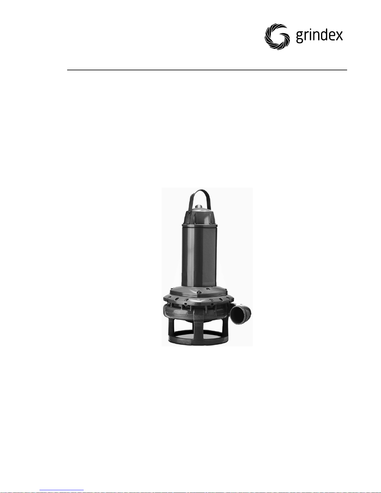
8153.020/.190 Bravo 900


Table of Contents
1 Introduction and Safety..................................................................................................... 3
1.1 Introduction.................................................................................... 3
1.2 Safety terminology and symbols.........................................................3
1.3 User safety......................................................................................4
1.4 Ex-approved products....................................................................... 4
1.5 Special hazards................................................................................5
1.6 Protecting the environment................................................................6
1.7 Spare parts..................................................................................... 7
1.8 Warranty.........................................................................................7
2 Transportation and Storage.............................................................................................. 8
2.1 Inspect the delivery..........................................................................8
2.1.1 Inspect the package....................................................................8
2.1.2 Inspect the unit.......................................................................... 8
2.2 Transportation guidelines...................................................................8
2.2.1 Lifting....................................................................................... 8
2.3 Temperature ranges for transportation, handling and storage................. 9
2.4 Storage guidelines............................................................................9
Table of Contents
3 Product Description......................................................................................................... 11
3.1 Products included........................................................................... 11
3.2 Pump design.................................................................................. 11
3.3 Parts.............................................................................................12
3.4 Monitoring equipment..................................................................... 13
3.5 The data plate................................................................................14
3.6 Approvals...................................................................................... 15
4 Installation........................................................................................................................ 17
4.1 Install the pump.............................................................................17
4.2 Make the electrical connections........................................................ 18
4.2.1 Prepare the SUBCAB® cables.......................................................20
4.2.2 Connect the motor cable to the pump.......................................... 21
4.2.3 Connect the motor cable to the starter and monitoring equipment... 22
4.2.4 Cable charts............................................................................. 22
4.2.5 Sensor connection.....................................................................28
4.3 Check the impeller rotation.............................................................. 29
5 Operation.......................................................................................................................... 31
5.1 Precautions....................................................................................31
5.2 Start the pump...............................................................................31
6 Maintenance..................................................................................................................... 33
6.1 Torque values.................................................................................34
6.2 Change the coolant.........................................................................34
6.2.1 Empty the coolant..................................................................... 35
6.2.2 Fill with coolant.........................................................................37
6.3 Replace the impeller....................................................................... 38
6.3.1 Remove the impeller..................................................................39
6.3.2 Install the impeller.................................................................... 41
6.4 Replace the agitator........................................................................43
8153.020/.190 Bravo 900 Installation, Operation, and Maintenance Manual 1

Table of Contents
6.4.1 Remove the agitator unit............................................................43
6.4.2 Install the agitator unit.............................................................. 44
6.5 Service the pump........................................................................... 44
6.5.1 Inspection................................................................................45
6.5.2 Major overhaul......................................................................... 46
6.5.3 Service in case of alarm............................................................. 46
7 Troubleshooting...............................................................................................................47
7.1 The pump does not start..................................................................47
7.2 The pump does not stop when a level sensor is used........................... 48
7.3 The pump starts-stops-starts in rapid sequence.................................. 49
7.4 The pump runs but the motor protection trips.....................................49
7.5 The pump delivers too little or no water.............................................50
8 Technical Reference........................................................................................................ 51
8.1 Application limits............................................................................ 51
8.2 Motor data.....................................................................................51
2 8153.020/.190 Bravo 900 Installation, Operation, and Maintenance Manual
1 Introduction and Safety
1.1 Introduction
Purpose of the manual
The purpose of this manual is to provide necessary information for working with
the unit. Read this manual carefully before starting work.
Read and keep the manual
Save this manual for future reference, and keep it readily available at the
location of the unit.
Intended use
WARNING:
Operating, installing, or maintaining the unit in any way that is not covered in
this manual could cause death, serious personal injury, or damage to the
equipment and the surroundings. This includes any modification to the
equipment or use of parts not provided by Grindex. If there is a question
regarding the intended use of the equipment, please contact a Grindex
representative before proceeding.
1 Introduction and Safety
Other manuals
See also the safety requirements and information in the original manufacturer's
manuals for any other equipment furnished separately for use in this system.
1.2 Safety terminology and symbols
About safety messages
It is extremely important that you read, understand, and follow the safety
messages and regulations carefully before handling the product. They are
published to help prevent these hazards:
• Personal accidents and health problems
• Damage to the product and its surroundings
• Product malfunction
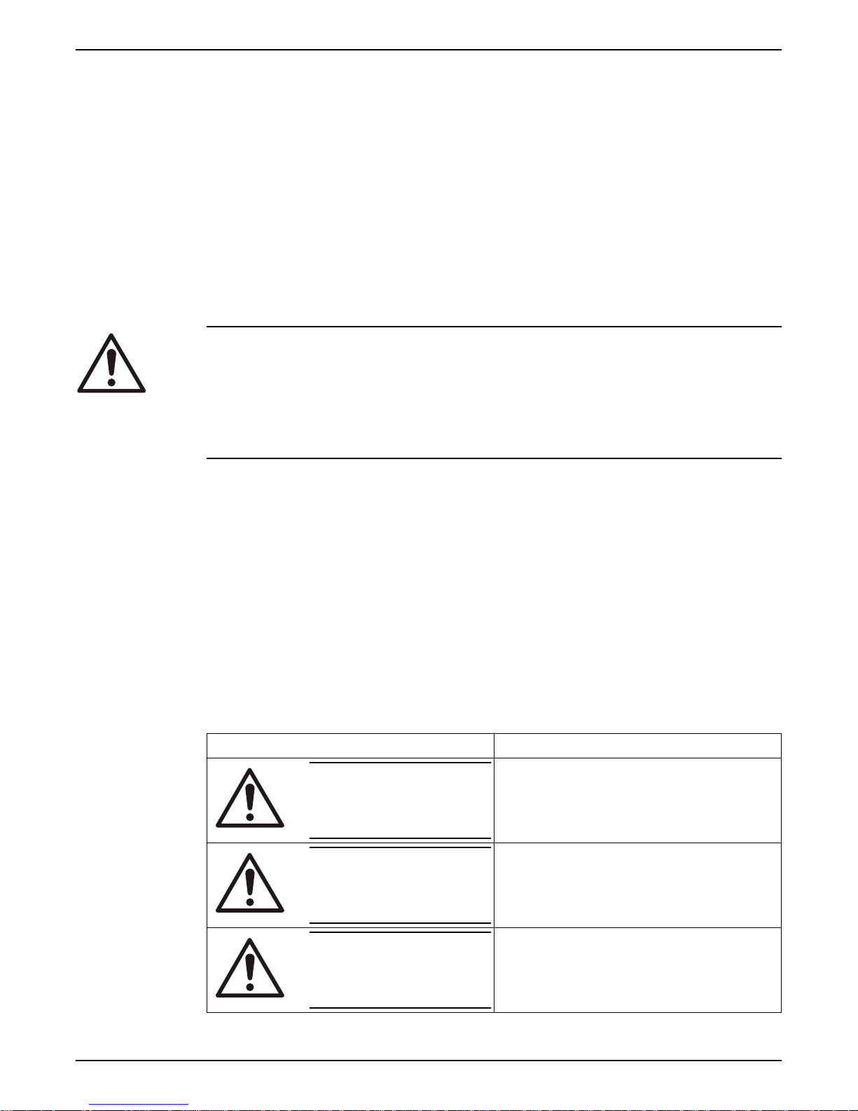
Hazard levels
Hazard level Indication
DANGER:
WARNING:
A hazardous situation which, if not
avoided, will result in death or serious
injury
A hazardous situation which, if not
avoided, could result in death or
serious injury
8153.020/.190 Bravo 900 Installation, Operation, and Maintenance Manual 3
CAUTION:
A hazardous situation which, if not
avoided, could result in minor or
moderate injury
1 Introduction and Safety
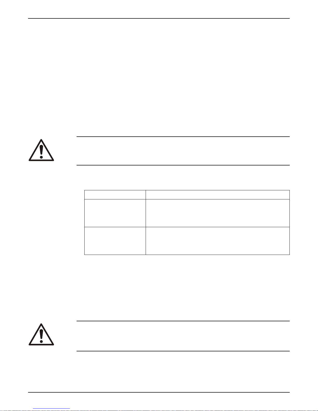
Hazard level Indication
NOTICE:
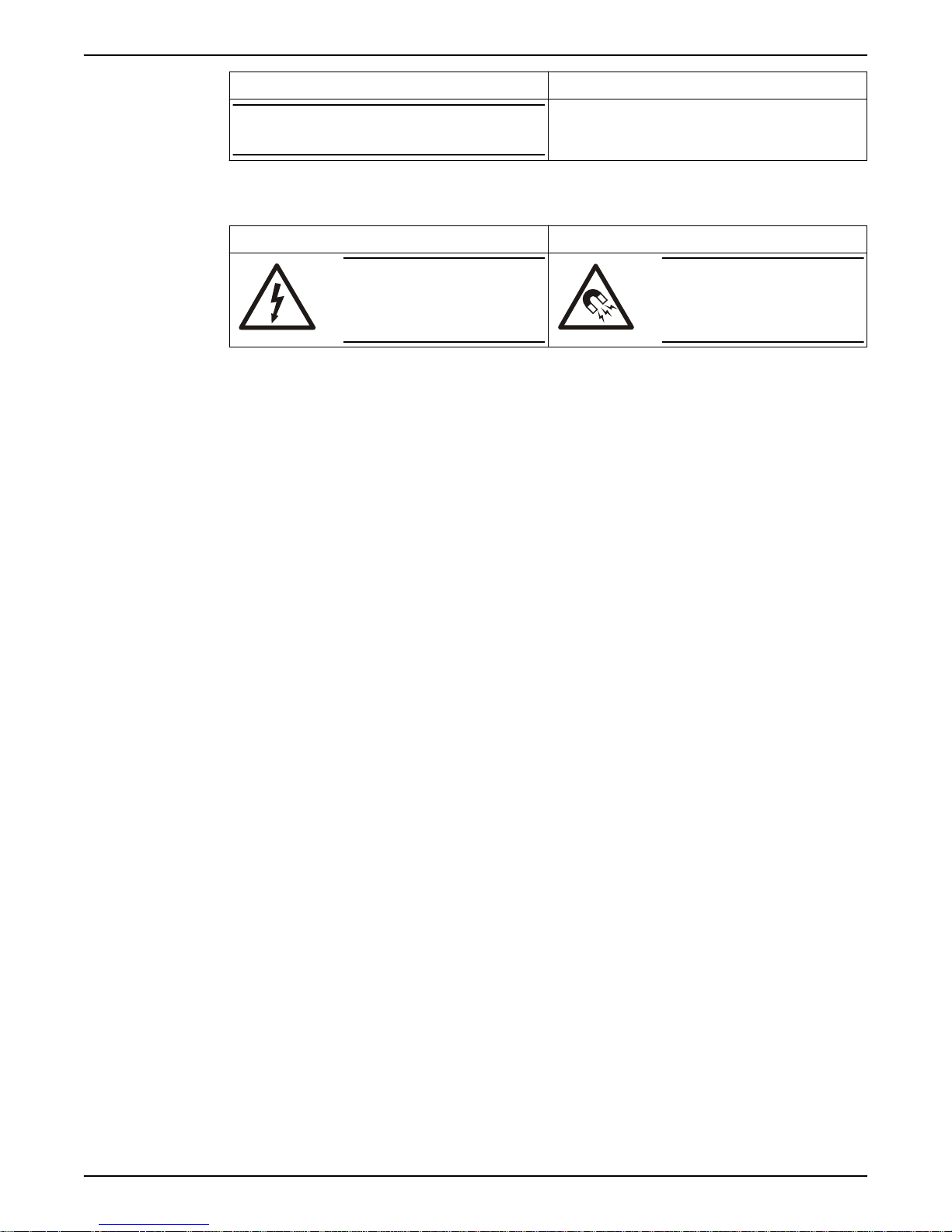
Special symbols
Some hazard categories have specific symbols, as shown in the following table.
Electrical hazard Magnetic fields hazard
1.3 User safety
All regulations, codes, and health and safety directives must be observed.
The site
• Observe lockout/tagout procedures before starting work on the product, such
as transportation, installation, maintenance, or service.
• Pay attention to the risks presented by gas and vapors in the work area.
• Always be aware of the area surrounding the equipment, and any hazards
posed by the site or nearby equipment.
Electrical Hazard:
Notices are used when there is a risk of
equipment damage or decreased
performance, but not personal injury.
CAUTION:
Qualified personnel
This product must be installed, operated, and maintained by qualified personnel
only.
Protective equipment and safety devices
• Use personal protective equipment as needed. Examples of personal
protective equipment include, but are not limited to, hard hats, safety
goggles, protective gloves and shoes, and breathing equipment.
• Make sure that all safety features on the product are functioning and in use at
all times when the unit is being operated.
1.4 Ex-approved products
Follow these special handling instructions if you have an Ex-approved unit.
Personnel requirements
These are the personnel requirements for Ex-approved products in potentially
explosive atmospheres:
• All work on the product must be carried out by certified electricians and
Grindex-authorized mechanics. Special rules apply to installations in explosive
atmospheres.
• All users must know about the risks of electric current and the chemical and
physical characteristics of the gas, the vapor, or both present in hazardous
areas.
• Any maintenance for Ex-approved products must conform to international and
national standards (for example, IEC/EN 60079-17).
Grindex disclaims all responsibility for work done by untrained and unauthorized
personnel.
Product and product handling requirements
These are the product and product handling requirements for Ex-approved
products in potentially explosive atmospheres:
4 8153.020/.190 Bravo 900 Installation, Operation, and Maintenance Manual

1 Introduction and Safety
• Only use the product in accordance with the approved motor data.
• You must fully submerge the Ex-approved product during normal operation.
Dry running during service and inspection is only permitted outside the
classified area.
• Before you start work on the product, make sure that the product and the
control panel are isolated from the power supply and the control circuit, so
they cannot be energized.
• Do not open the product while it is energized or in an explosive gas
atmosphere.
• Make sure that thermal contacts are connected to a protection circuit
according to the approval classification of the product, and that they are in
use.
• Intrinsically safe circuits are normally required for the automatic level-control
system by the level regulator if mounted in zone 0.
• The yield stress of fasteners must be in accordance with the approval drawing
and the product specification.
• Do not modify the equipment without approval from an authorized Grindex
representative.
• Only use parts that are provided by an authorized Grindex representative.
• The thermal detectors fitted to the stator windings must be connected into
the motor control circuit in such a manner as to disconnect the supply to the
motor in order to prevent the Temperature Class T3.
• The width of flameproof joints is more than the values specified in the tables
of the IEC 60079–1 standard.
• The gap of flameproof joints is less than the values specified in Table 1 of the
IEC 60079–1 standard.
• The equipment must be submerged during normal operation.
Guidelines for compliance
Compliance is fulfilled only when you operate the unit within its intended use. Do
not change the conditions of the service without the approval of a Grindex
representative. When you install or maintain explosion proof products, always
comply with the directive and applicable standards (for example, IEC/EN 60079–
14).
Minimum permitted liquid level
See the dimensional drawings of the product for the minimum permitted liquid
level according to the approval for explosion proof products. If the information is
missing on the dimensional drawing, the product must be fully submerged.
Level-sensing equipment must be installed if the product can be operated at less
than the minimum submersion depth.
Monitoring equipment
For additional safety, use condition-monitoring devices. Examples of conditionmonitoring devices include, but are not limited to, the following:
• Level indicators
• Temperature detectors in addition to the stator thermal detectors
Any thermal detectors or thermal protection devices delivered with the pump
must be installed and in use at all times.
1.5 Special hazards
Working in temporary installations
Certain industries, such as mining or construction, have a dynamic nature and
require temporary installation of equipment. Due to the rugged nature of these
applications, normal use of electrical equipment causes wear and tear that can
8153.020/.190 Bravo 900 Installation, Operation, and Maintenance Manual 5
1 Introduction and Safety
result in insulation breaks, short-circuits, and exposed wires. To maximize safety
when using the unit in rugged applications, the following conditions must be
met:
• If electrical cables must be located such that they are at risk of being run
over by heavy equipment, then provide mechanical protection to prevent
physical damage to the cables.
• Visually inspect electrical equipment before use. Remove from service any
equipment with exposed wires or visible damage.
• Use ground-fault circuit interrupters on all receptacles, or have an assured
equipment grounding conductor program.
Biological hazards
The product is designed for use in liquids that can be hazardous to your health.
Observe these rules when you work with the product:
• Make sure that all personnel who may come into contact with biological
hazards are vaccinated against diseases to which they may be exposed.
• Observe strict personal cleanliness.
WARNING: Biological Hazard
Infection risk. Rinse the unit thoroughly with clean water before working on it.
Wash the skin and eyes
Follow these procedures for chemicals or hazardous fluids that have come into
contact with your eyes or your skin:
Condition Action
Chemicals or
hazardous fluids in
eyes
Chemicals or
hazardous fluids on
skin
1. Hold your eyelids apart forcibly with your fingers.
2. Rinse the eyes with eyewash or running water for
3. Seek medical attention.
1. Remove contaminated clothing.
2. Wash the skin with soap and water for at least 1
3. Seek medical attention, if necessary.
1.6 Protecting the environment
Emissions and waste disposal
Observe the local regulations and codes regarding:
• Reporting of emissions to the appropriate authorities
• Sorting, recycling and disposal of solid or liquid waste
• Clean-up of spills
Exceptional sites
at least 15 minutes.
minute.
CAUTION: Radiation Hazard
Do NOT send the product to Xylem if it has been exposed to nuclear radiation,
unless Xylem has been informed and appropriate actions have been agreed
upon.
6 8153.020/.190 Bravo 900 Installation, Operation, and Maintenance Manual

1.7 Spare parts
CAUTION:
Only use the manufacturer’s original spare parts to replace any worn or faulty
components. The use of unsuitable spare parts may cause malfunctions,
damage, and injuries as well as void the warranty.
1.8 Warranty
For information about warranty, see the sales contract.
1 Introduction and Safety
8153.020/.190 Bravo 900 Installation, Operation, and Maintenance Manual 7

2 Transportation and Storage
2 Transportation and Storage
2.1 Inspect the delivery
2.1.1 Inspect the package
1. Inspect the package for damaged or missing items upon delivery.
2. Note any damaged or missing items on the receipt and freight bill.
3. File a claim with the shipping company if anything is out of order.
If the product has been picked up at a distributor, make a claim directly to the
distributor.
2.1.2 Inspect the unit
1. Remove packing materials from the product.
Dispose of all packing materials in accordance with local regulations.
2. Inspect the product to determine if any parts have been damaged or are
missing.
3. If applicable, unfasten the product by removing any screws, bolts, or straps.
For your personal safety, be careful when you handle nails and straps.
4. Contact the local sales representative if there is any issue.
2.2 Transportation guidelines
Precautions
DANGER: Crush Hazard
Moving parts can entangle or crush. Always disconnect and lock out power
before servicing to prevent unexpected startup. Failure to do so could result in
death or serious injury.
Position and fastening
The unit can be transported either horizontally or vertically. Make sure that the
unit is securely fastened during transportation, and cannot roll or fall over.
2.2.1 Lifting
Always inspect the lifting equipment and tackle before starting any work.
WARNING: Crush Hazard
1) Always lift the unit by its designated lifting points. 2) Use suitable lifting
equipment and ensure that the product is properly harnessed. 3) Wear personal
protective equipment. 4) Stay clear of cables and suspended loads.
NOTICE:
Never lift the unit by its cables or hose.
Lifting equipment
Lifting equipment is always required when handling the unit. It must fulfill the
following requirements:
• The minimum height (contact Grindex for information) between the lifting
hook and the floor must be sufficient to lift the unit.
• The lifting equipment must be able to hoist the unit straight up and down,
preferably without the need for resetting the lifting hook.
8 8153.020/.190 Bravo 900 Installation, Operation, and Maintenance Manual
2 Transportation and Storage
• The lifting equipment must be securely anchored and in good condition.
• The lifting equipment must support weight of the entire assembly and must
only be used by authorized personnel.
• Two sets of lifting equipment must be used to lift the unit for repair work.
• The lifting equipment must be dimensioned to lift the unit with any remaining
pumped media in it.
• The lifting equipment must not be oversized.
CAUTION: Crush Hazard
Over-dimensioned lifting equipment can lead to injury. A sitespecific risk analysis must be done.
2.3 Temperature ranges for transportation, handling and storage
Handling at freezing temperature
At temperatures below freezing, the product and all installation equipment,
including the lifting gear, must be handled with extreme care.
Make sure that the product is warmed up to a temperature above the freezing
point before starting up. Avoid rotating the impeller/propeller by hand at
temperatures below the freezing point. The recommended method to warm the
unit up is to submerge it in the liquid which will be pumped or mixed.
NOTICE:
Never use a naked flame to thaw the unit.
Unit in as-delivered condition
If the unit is still in the condition in which it left the factory - all packing
materials are undisturbed - then the acceptable temperature range during
transportation, handling and storage is: –50°C (–58ºF) to +60°C (+140ºF).
If the unit has been exposed to freezing temperatures, then allow it to reach the
ambient temperature of the sump before operating.
Lifting the unit out of liquid
The unit is normally protected from freezing while operating or immersed in
liquid, but the impeller/propeller and the shaft seal may freeze if the unit is lifted
out of the liquid into a surrounding temperature below freezing.
Units equipped with an internal cooling system are filled with a mixture of water
and 30% glycol. This mixture remains a flowing liquid at temperatures down to –
13°C (9°F). Below –13°C (9°F), the viscosity increases such that the glycol
mixture will lose its flow properties. However, the glycol-water mixture will not
solidify completely and thus cannot harm the product.
Follow these guidelines to avoid freezing damage:
1. Empty all pumped liquid, if applicable.
2. Check all liquids used for lubrication or cooling, both oil and water-glycol
mixtures, for the presence of unacceptable amounts of water. Change if
needed.
2.4 Storage guidelines
Storage location
The product must be stored in a covered and dry location free from heat, dirt,
and vibrations.
8153.020/.190 Bravo 900 Installation, Operation, and Maintenance Manual 9

2 Transportation and Storage
NOTICE:
Protect the product against humidity, heat sources, and mechanical damage.
NOTICE:
Do not place heavy weights on the packed product.
Long-term storage
If the unit is stored more than six months, then the following apply:
• Before operating the unit after storage, it must be inspected with special
attention to the seals and the cable entry.
• The impeller/propeller must be rotated every other month to prevent the
seals from sticking together.
10 8153.020/.190 Bravo 900 Installation, Operation, and Maintenance Manual
3 Product Description
3.1 Products included
Pump model Standard EX Slurry
Bravo 900, 8153.020 X X
Bravo 900, 8153.190 X X
3.2 Pump design
The pump is submersible, and driven by an electric motor.
Intended use
The product is intended for moving waste water, sludge, raw and clean water.
Always follow the application limits given in Technical Reference (page 51). If
there is a question regarding the intended use of the equipment, please contact
an Grindex representative before proceeding.
DANGER: Explosion/Fire Hazard
Special rules apply to installations in explosive or flammable atmospheres. Do
not install the product or any auxiliary equipment in an explosive zone unless it
is rated explosion-proof or intrinsically-safe. If the product is EN/ATEX-, MSHAor FM-approved, then see the specific EX information in the Safety chapter
before taking any further actions.
3 Product Description
Spare parts
Pressure class
NOTICE:
Do NOT use the unit in highly corrosive liquids.
• Modifications to the unit or installation should only be carried out after
consulting with Grindex.
• Original spare parts and accessories authorized by Grindex are essential for
compliance. The use of other parts can invalidate any claims for warranty or
compensation. For more information contact your Grindex representative.
N Medium head
8153.020/.190 Bravo 900 Installation, Operation, and Maintenance Manual 11
10
11
9
8
7
6
5
1
2
3
4
WS006111A
13
WS000353A
12
WS006110A
3 Product Description
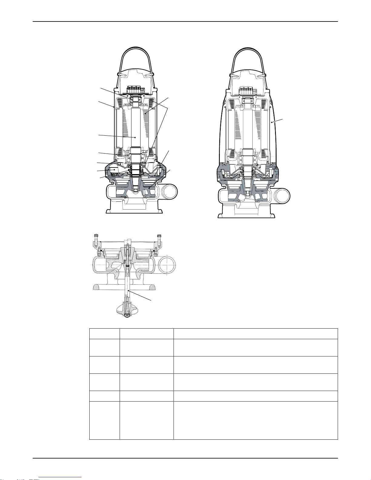
3.3 Parts
Figure 1: Without cooling jacket
Position Part Description
Figure 2: With cooling jacket
1 Motor For information about the motor, see Technical
Reference (page 51).
2 Monitoring
equipment
For more information about the monitoring
equipment, see Monitoring equipment (page 13).
3 Flow diffuser Provides heat transfer from the coolant to the
pumped media (liquid).
4 Impeller The impeller is a shrouded three-channel H-impeller.
5 Mechanical seals One inner and one outer seal in a combination of
materials:
• Tungsten carbide
• Silicon carbide RSiC
• Aluminium oxide Al2O
• Corrosion-resistant cemented carbide WCCR
3
12 8153.020/.190 Bravo 900 Installation, Operation, and Maintenance Manual
3 Product Description
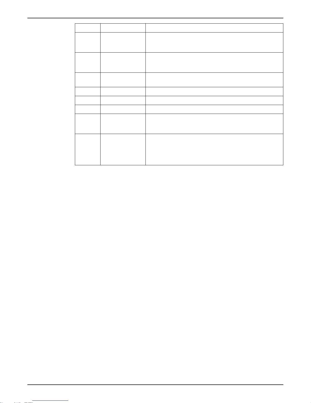
Position Part Description
6 Seal housing Includes a coolant that lubricates and cools the
seals; the housing acts as a buffer between the
pumped liquid and the electric motor.
External cooling
7 Inspection
chamber
8 Main bearing The bearing consists of a two row angular contact
9 Shaft The shaft is stainless steel, with an integrated rotor.
10 Cooling The pump is cooled by the ambient liquid.
11 Support bearing The bearing consists of a two-row ball bearing.
12 Agitator The agitator stirs the slurry in order to prevent
13 Cooling with
cooling jacket
The following items are required in order to use external cooling:
• Cooling jacket
• Inlet/outlet pipes with M16 threads (replacing the coolant plugs)
• External cooling system (hose, water source, etc.)
Contact your local Grindex representative for more information.
The inspection chamber is equipped with a FLS10
leakage sensor in order to prevent damages on the
motor.
ball bearing.
deposition of material on the sump bottom. Use of
the agitator is optional.
The motor is cooled by a closed loop system. An
integrated coolant pump circulates the coolant
whenever the pump is operated. The cooling jacket
can also be used with a external cooling system. For
more information, see External cooling (page 13).
3.4 Monitoring equipment
The following applies to the monitoring equipment of the pump:
• The stator incorporates three thermal contacts connected in series that
activate the alarm and stops the pump at overtemperature
• The thermal contacts open at 140°C (285°F).
• Ex-approved pumps must have thermal contacts connected to the control
panel.
• The sensors and optional sensors must be connected to the monitoring
equipment.
• The monitoring equipment must be of a design that makes automatic restart
impossible.
• The pump is supplied with an inspection sensor FLS 10 for sensing the
presence of any liquid in the inspection chamber.
• Information in the junction box shows if the pump is equipped with optional
sensors.
Optional sensors
Thermistor Thermistors are optional sensors for measuring the temperature.
They are connected in series in the stator and activate the alarm at
overtemperature. Thermistors are not applicable to Ex-approved
pumps.
8153.020/.190 Bravo 900 Installation, Operation, and Maintenance Manual 13
1
2
3
4
5
6
7
8910111213
14
15
16
18
17
19
WS001008C
3 Product Description
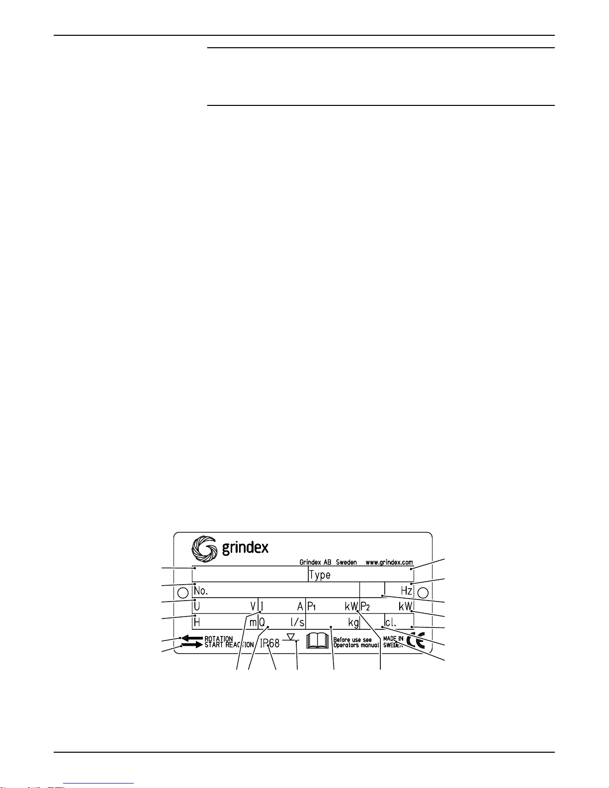
3.5 The data plate
Introduction
The data plate is a metal label located on the main body of the pump. The data
plate lists key product specifications.
The data plate
This list of callouts is applicable for all versions of data plates:
1. Pump type number
2. Frequency
3. Phases, type of current
4. Rated shaft power
5. Thermal class
6. Locked rotor code-letter
7. Country of origin
8. Maximum power consumption
9. Product weight
10.Maximum submersion depth
11.Degree of protection
12.Maximum capacity
13.Rated current
14.Direction of the start reaction
15.Direction of the impeller rotation
16.Maximum head
17.Serial number
The first two characters describe the production year.
18.Rated voltage
19.Pump model
This is the data plate for non explosion-proof version .020:
NOTICE:
Thermistors must never be exposed to voltages higher than 2.5 V. If
the voltage exceeds this value, for example when the control circuit
is tested, then the thermistors will be destroyed.
14 8153.020/.190 Bravo 900 Installation, Operation, and Maintenance Manual
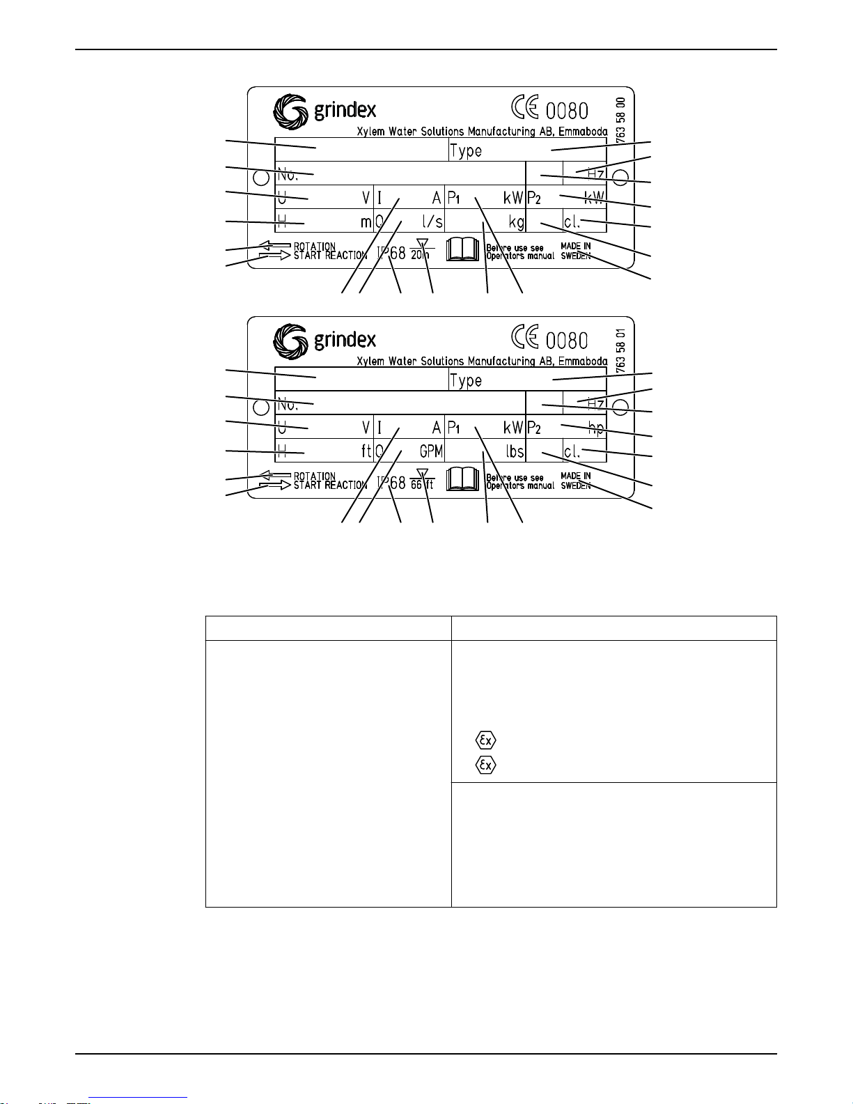
These are the data plates for explosion-proof version .190:
1
2
3
4
5
6
7
14
15
16
18
17
19
8910111213
WS001006C
WS001007C
1
2
3
4
5
6
7
14
15
16
18
17
19
8910111213
3 Product Description
3.6 Approvals
Product approvals for hazardous locations
Pump Approval
8153.190 European Norm (EN)
EN approval plate
This illustration describes the EN approval plate and the information that is
contained in its fields.
8153.020/.190 Bravo 900 Installation, Operation, and Maintenance Manual 15
• ATEX Directive
• EN 60079-0:2012/A11:2013,
EN 60079-1:2007, EN 13463-1:2009,
EN 13463-5:2011
•
I M2 c Ex d I Mb
•
II 2 G c Ex d IIB T3 Gb
FM (FM Approvals)
• Explosion proof for use in Class I, Div. 1,
Group C and D
• Dust ignition proof for use in Class II, Div.
1, Group E, F and G
• Suitable for use in Class III, Div. 1,
Hazardous Locations
 Loading...