

Page 1
www.grindex.com
Installation, Operation, and Maintenance
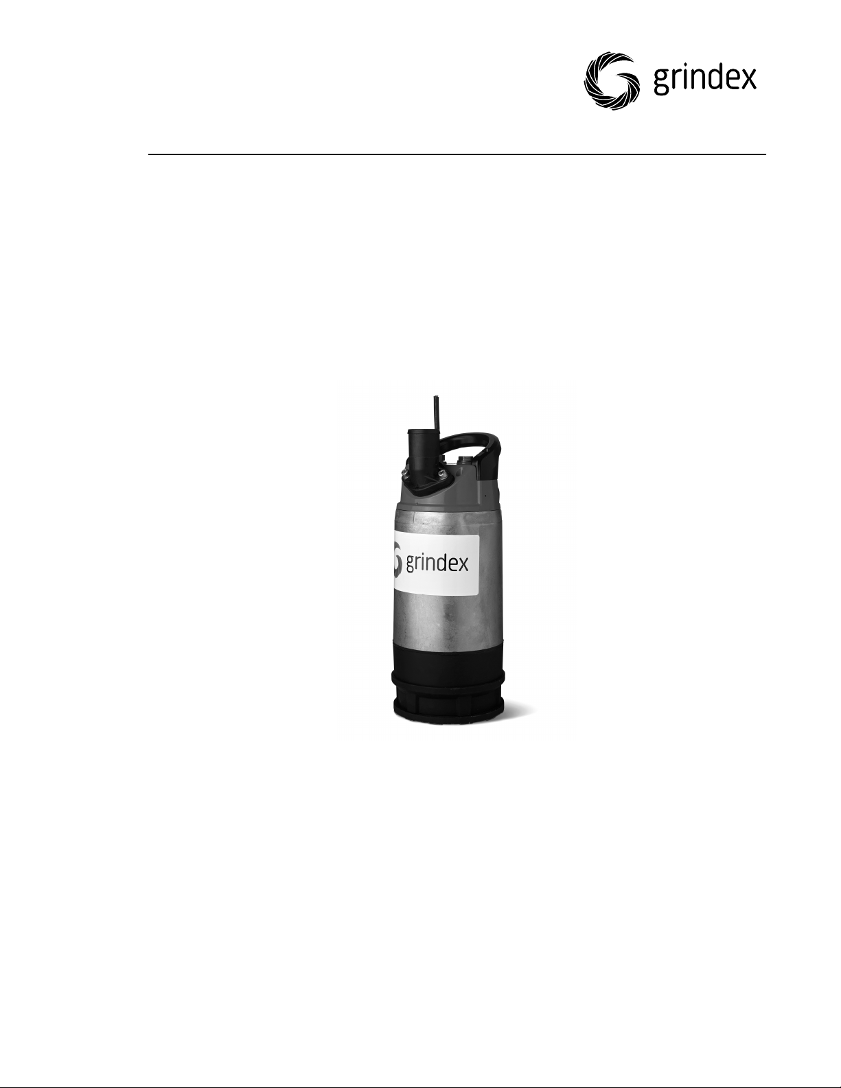
8125.230 Milli
Page 2

Page 3

Table of Contents
1 Introduction and Safety..................................................................................................... 3
1.1 Introduction.................................................................................... 3
1.2 Safety terminology and symbols.........................................................3
1.3 User safety......................................................................................4
1.4 Special hazards................................................................................4
1.5 Protecting the environment................................................................5
1.6 Spare parts..................................................................................... 5
1.7 Warranty.........................................................................................5
2 Transportation and Storage.............................................................................................. 6
2.1 Inspect the delivery..........................................................................6
2.1.1 Inspect the package....................................................................6
2.1.2 Inspect the unit.......................................................................... 6
2.2 Transportation guidelines...................................................................6
2.2.1 Lifting....................................................................................... 6
2.3 Temperature ranges for transportation, handling and storage................. 7
2.4 Storage guidelines............................................................................7
Table of Contents
3 Product Description...........................................................................................................9
3.1 Products included............................................................................. 9
3.2 Pump design....................................................................................9
3.3 Monitoring equipment....................................................................... 9
3.3.1 Level regulators........................................................................ 10
3.4 The data plate................................................................................10
4 Installation........................................................................................................................ 12
4.1 Install the pump.............................................................................12
4.1.1 Install......................................................................................13
4.2 Make the electrical connections........................................................ 14
4.2.1 Connect the motor cable to the pump.......................................... 16
4.2.2 Cable charts............................................................................. 17
4.3 Check the impeller rotation.............................................................. 18
5 Operation.......................................................................................................................... 20
5.1 Precautions....................................................................................20
5.2 Start the pump...............................................................................20
5.2.1 Fill with water ..........................................................................21
5.3 Clean the pump..............................................................................21
6 Maintenance..................................................................................................................... 22
6.1 Torque values.................................................................................23
6.2 Service..........................................................................................23
6.3 Change the oil................................................................................24
6.4 Replace the impeller....................................................................... 25
6.4.1 Remove the impeller..................................................................25
6.4.2 Install the impeller.................................................................... 26
6.5 Replace the motor cable.................................................................. 28
6.5.1 Remove the motor cable............................................................ 28
6.5.2 Install the motor cable...............................................................29
8125.230 Milli Installation, Operation, and Maintenance 1
Page 4

Table of Contents
7 Troubleshooting...............................................................................................................32
7.1 The pump does not start..................................................................32
7.2 The pump does not stop when a level sensor is used........................... 33
7.3 The pump starts-stops-starts in rapid sequence.................................. 34
7.4 The pump runs but the motor protection trips.....................................34
7.5 The pump delivers too little or no water.............................................35
8 Technical Reference........................................................................................................ 37
8.1 Application limits............................................................................ 37
8.2 Motor data.....................................................................................37
8.3 Specific motor data.........................................................................37
8.4 Dimensions and weights.................................................................. 38
8.5 Performance curves........................................................................ 39
2 8125.230 Milli Installation, Operation, and Maintenance
Page 5
1 Introduction and Safety
1.1 Introduction
Purpose of the manual
The purpose of this manual is to provide necessary information for working with
the unit. Read this manual carefully before starting work.
Read and keep the manual
Save this manual for future reference, and keep it readily available at the
location of the unit.
Intended use
WARNING:
Operating, installing, or maintaining the unit in any way that is not covered in
this manual could cause death, serious personal injury, or damage to the
equipment and the surroundings. This includes any modification to the
equipment or use of parts not provided by Grindex. If there is a question
regarding the intended use of the equipment, please contact a Grindex
representative before proceeding.
1 Introduction and Safety
Other manuals
See also the safety requirements and information in the original manufacturer's
manuals for any other equipment furnished separately for use in this system.
1.2 Safety terminology and symbols
About safety messages
It is extremely important that you read, understand, and follow the safety
messages and regulations carefully before handling the product. They are
published to help prevent these hazards:
• Personal accidents and health problems
• Damage to the product and its surroundings
• Product malfunction
Hazard levels
Hazard level Indication
DANGER:
WARNING:
A hazardous situation which, if not
avoided, will result in death or serious
injury
A hazardous situation which, if not
avoided, could result in death or
serious injury
CAUTION:
8125.230 Milli Installation, Operation, and Maintenance 3
A hazardous situation which, if not
avoided, could result in minor or
moderate injury
Page 6
1 Introduction and Safety
Hazard level Indication
NOTICE:
Special symbols
Some hazard categories have specific symbols, as shown in the following table.
Electrical hazard Magnetic fields hazard
1.3 User safety
All regulations, codes, and health and safety directives must be observed.
The site
• Observe lockout/tagout procedures before starting work on the product, such
as transportation, installation, maintenance, or service.
• Pay attention to the risks presented by gas and vapors in the work area.
• Always be aware of the area surrounding the equipment, and any hazards
posed by the site or nearby equipment.
Electrical Hazard:
Notices are used when there is a risk of
equipment damage or decreased
performance, but not personal injury.
CAUTION:
Qualified personnel
This product must be installed, operated, and maintained by qualified personnel
only.
Protective equipment and safety devices
• Use personal protective equipment as needed. Examples of personal
protective equipment include, but are not limited to, hard hats, safety
goggles, protective gloves and shoes, and breathing equipment.
• Make sure that all safety features on the product are functioning and in use at
all times when the unit is being operated.
1.4 Special hazards
Working in temporary installations
Certain industries, such as mining or construction, have a dynamic nature and
require temporary installation of equipment. Due to the rugged nature of these
applications, normal use of electrical equipment causes wear and tear that can
result in insulation breaks, short-circuits, and exposed wires. To maximize safety
when using the unit in rugged applications, the following conditions must be
met:
• If electrical cables must be located such that they are at risk of being run
over by heavy equipment, then provide mechanical protection to prevent
physical damage to the cables.
• Visually inspect electrical equipment before use. Remove from service any
equipment with exposed wires or visible damage.
• Use ground-fault circuit interrupters on all receptacles, or have an assured
equipment grounding conductor program.
Biological hazards
The product is designed for use in liquids that can be hazardous to your health.
Observe these rules when you work with the product:
4 8125.230 Milli Installation, Operation, and Maintenance
Page 7
• Make sure that all personnel who may come into contact with biological
hazards are vaccinated against diseases to which they may be exposed.
• Observe strict personal cleanliness.
WARNING: Biological Hazard
Infection risk. Rinse the unit thoroughly with clean water before working on it.
Wash the skin and eyes
Follow these procedures for chemicals or hazardous fluids that have come into
contact with your eyes or your skin:
Condition Action
1 Introduction and Safety
Chemicals or
hazardous fluids in
eyes
Chemicals or
hazardous fluids on
skin
1. Hold your eyelids apart forcibly with your fingers.
2. Rinse the eyes with eyewash or running water for
3. Seek medical attention.
1. Remove contaminated clothing.
2. Wash the skin with soap and water for at least 1
3. Seek medical attention, if necessary.
1.5 Protecting the environment
Emissions and waste disposal
Observe the local regulations and codes regarding:
• Reporting of emissions to the appropriate authorities
• Sorting, recycling and disposal of solid or liquid waste
• Clean-up of spills
Exceptional sites
CAUTION: Radiation Hazard
Do NOT send the product to Grindex if it has been exposed to nuclear radiation,
unless Grindex has been informed and appropriate actions have been agreed
upon.
at least 15 minutes.
minute.
1.6 Spare parts
CAUTION:
Only use the manufacturer’s original spare parts to replace any worn or faulty
components. The use of unsuitable spare parts may cause malfunctions,
damage, and injuries as well as void the warranty.
1.7 Warranty
For information about warranty, see the sales contract.
8125.230 Milli Installation, Operation, and Maintenance 5
Page 8

Equipment
locked out by
Name .......................
DANGER
2 Transportation and Storage
2 Transportation and Storage
2.1 Inspect the delivery
2.1.1 Inspect the package
1. Inspect the package for damaged or missing items upon delivery.
2. Note any damaged or missing items on the receipt and freight bill.
3. File a claim with the shipping company if anything is out of order.
If the product has been picked up at a distributor, make a claim directly to the
distributor.
2.1.2 Inspect the unit
1. Remove packing materials from the product.
Dispose of all packing materials in accordance with local regulations.
2. Inspect the product to determine if any parts have been damaged or are
missing.
3. If applicable, unfasten the product by removing any screws, bolts, or straps.
For your personal safety, be careful when you handle nails and straps.
4. Contact a sales representative if there is any issue.
2.2 Transportation guidelines
Precautions
DANGER: Crush Hazard
Moving parts can entangle or crush. Always disconnect and lock out power
before servicing to prevent unexpected startup. Failure to do so could result in
death or serious injury.
Position and fastening
The unit can be transported either horizontally or vertically. Make sure that the
unit is securely fastened during transportation, and cannot roll or fall over.
2.2.1 Lifting
Always inspect the lifting equipment and tackle before starting any work.
WARNING: Crush Hazard
1) Always lift the unit by its designated lifting points. 2) Use suitable lifting
equipment and ensure that the product is properly harnessed. 3) Wear personal
protective equipment. 4) Stay clear of cables and suspended loads.
6 8125.230 Milli Installation, Operation, and Maintenance
Page 9

2 Transportation and Storage
NOTICE:
Never lift the unit by its cables or hose.
2.3 Temperature ranges for transportation, handling and storage
Handling at freezing temperature
At temperatures below freezing, the product and all installation equipment,
including the lifting gear, must be handled with extreme care.
Make sure that the product is warmed up to a temperature above the freezing
point before starting up. Avoid rotating the impeller/propeller by hand at
temperatures below the freezing point. The recommended method to warm the
unit up is to submerge it in the liquid which will be pumped or mixed.
NOTICE:
Never use a naked flame to thaw the unit.
Unit in as-delivered condition
If the unit is still in the condition in which it left the factory - all packing
materials are undisturbed - then the acceptable temperature range during
transportation, handling and storage is: –50°C (–58ºF) to +60°C (+140ºF).
If the unit has been exposed to freezing temperatures, then allow it to reach the
ambient temperature of the sump before operating.
Lifting the unit out of liquid
The unit is normally protected from freezing while operating or immersed in
liquid, but the impeller/propeller and the shaft seal may freeze if the unit is lifted
out of the liquid into a surrounding temperature below freezing.
Follow these guidelines to avoid freezing damage:
1. Empty all pumped liquid, if applicable.
2. Check all liquids used for lubrication or cooling, both oil and water-glycol
mixtures, for the presence of unacceptable amounts of water. Change if
needed.
Water-glycol mixtures: Units equipped with an internal closed-loop cooling
system are filled with a mixture of water and 30% glycol. This mixture remains a
flowing liquid at temperatures down to –13°C (9°F). Below –13°C (9°F), the
viscosity increases such that the glycol mixture will lose its flow properties.
However, the glycol-water mixture will not solidify completely and thus cannot
harm the product.
2.4 Storage guidelines
Storage location
The product must be stored in a covered and dry location free from heat, dirt,
and vibrations.
NOTICE:
Protect the product against humidity, heat sources, and mechanical damage.
NOTICE:
Do not place heavy weights on the packed product.
Long-term storage
If the unit is stored more than six months, then the following apply:
8125.230 Milli Installation, Operation, and Maintenance 7
Page 10

2 Transportation and Storage
• Before operating the unit after storage, it must be inspected with special
attention to the seals and the cable entry.
• The impeller/propeller must be rotated every other month to prevent the
seals from sticking together.
8 8125.230 Milli Installation, Operation, and Maintenance
Page 11
3 Product Description
3.1 Products included
Pump model Standard EX MSHA Drainage Sludge
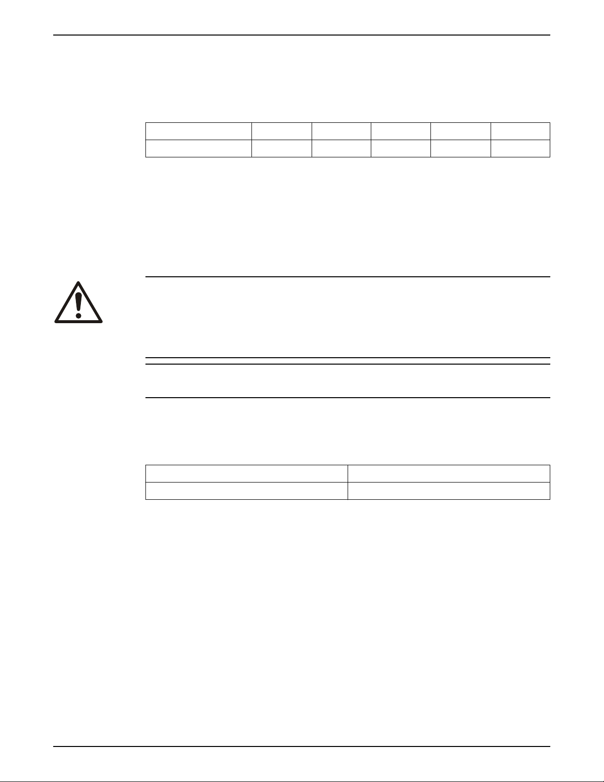
Milli 8125.230 X X
3.2 Pump design
The pump is submersible, and driven by an electric motor.
Intended use
The product is intended for moving waste water, sludge, raw and clean water.
Always follow the limits given in Application limits. If there is a question
regarding the intended use of the equipment, then contact a sales or authorized
service representative before proceeding.
DANGER: Explosion/Fire Hazard
Special rules apply to installations in explosive or flammable atmospheres. Do
not install the product or any auxiliary equipment in an explosive zone unless it
is rated explosion-proof or intrinsically-safe. If the product is EN/ATEX-, MSHAor FM-approved, then see the specific EX information in the Safety chapter
before taking any further actions.
3 Product Description
NOTICE:
Do NOT use the unit in highly corrosive liquids.
For information about pH, see Application limits.
Particle size
The pump can handle liquid containing particles that correspond to the holes in
the strainer.
Number of holes Hole dimensions
61 5.2 mm (0.2 in)
Pressure class
N Medium head
Impeller type
Wear resistant
3.3 Monitoring equipment
The following applies to the monitoring equipment of the pump:
• The stator incorporates thermal contacts connected in series that activate the
alarm at overtemperature.
• The thermal contacts open at 135°C (275°F).
8125.230 Milli Installation, Operation, and Maintenance 9
Page 12
1
2
WS006210B
3 Product Description
3.3.1 Level regulators
About level regulators
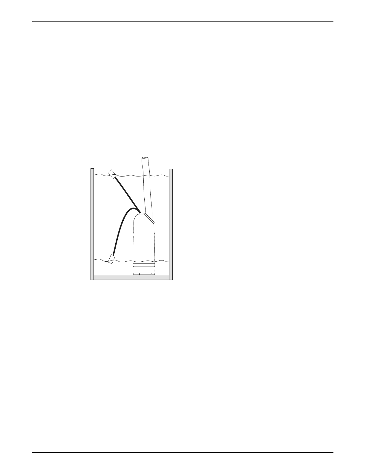
Starting and stopping the pump at different water levels can be manual or
automatic. If automatic start and stop is required, a level regulator can be
ordered (as an option). The option is only available for standard pumps.
Features
Below are some of the features of the level regulators:
• The level regulator can be set at different operating levels by adjusting the
length of cable.
• A clamping bracket situated at the lifting handle holds the level regulator
cable in place.
• If continuous pumping is required, the level regulator can be placed in a
special rubber bracket on the discharge connection to eliminate the level
regulator function.
Illustration
1. On
2. Off
Figure 1: The functionality of the level regulator
3.4 The data plate
Introduction
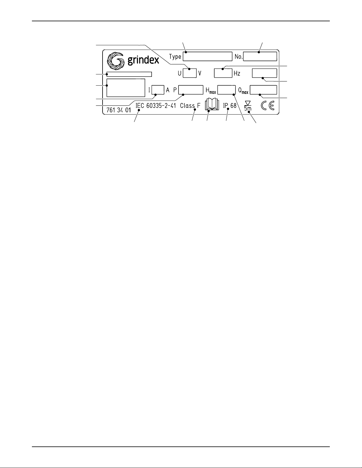
The data plate is a metal label located on the main body of the pump. The data
plate lists key product specifications.
10 8125.230 Milli Installation, Operation, and Maintenance
Page 13
The data plate
WS006202B
1
2
3
4
5
7 610 9 811
13
12
14
16
15
3 Product Description
1. Pump model
2. Serial number
The first two characters describe the production year.
3. Phase; type of current; frequency
4. Product weight
5. Maximum capacity
6. Maximum submergence
7. Maximum head
8. Degree of protection
9. Read installation manual
10.Thermal class
11.International standard
12.Maximum power consumption
13.Rated current
14.Manufacturer
15.Country of origin
16.Rated voltage
8125.230 Milli Installation, Operation, and Maintenance 11
Page 14
Equipment
locked out by
Name .......................
DANGER
4 Installation
4 Installation
4.1 Install the pump
Before starting work, make sure that the safety instructions in the chapter
Introduction and Safety on page 3 have been read and understood.
DANGER: Electrical Hazard
Before starting work on the unit, make sure that the unit and the control panel
are isolated from the power supply and cannot be energized. This applies to the
control circuit as well.
DANGER: Inhalation Hazard
Before entering the work area, make sure that the atmosphere contains
sufficient oxygen and no toxic gases.
Hazardous atmospheres
DANGER: Explosion/Fire Hazard
Special rules apply to installations in explosive or flammable atmospheres. Do
not install the product or any auxiliary equipment in an explosive zone unless it
is rated explosion-proof or intrinsically-safe. If the product is EN/ATEX-, MSHAor FM-approved, then see the specific EX information in the Safety chapter
before taking any further actions.
WARNING: Explosion/Fire Hazard
Do not install CSA-approved products in locations that are classified as
hazardous in the National Electric Code(TM), ANSI/NFPA 70-2005.
Authority regulation
Vent the tank of a sewage station in accordance with local plumbing codes.
Sedimentation prevention
In order to avoid sedimentation when the pumped liquid contains solid particles,
the velocity of the liquid in the discharge line must exceed a certain value.
Choose applicable minimum velocity from the table, and choose proper
dimension of the discharge line accordingly.
Mixture Minimum velocity, meter per
second (feet per second)
Water + coarse gravel 4 (13)
Water + gravel 3.5 (11)
12 8125.230 Milli Installation, Operation, and Maintenance
Page 15
WS001380B
WS001379A
WS001346A
4 Installation
Mixture Minimum velocity, meter per
second (feet per second)
Water + sand, particle size <0.6 mm
(0.024 in)
Water + sand, particle size <0.1 mm
(0.004 in)
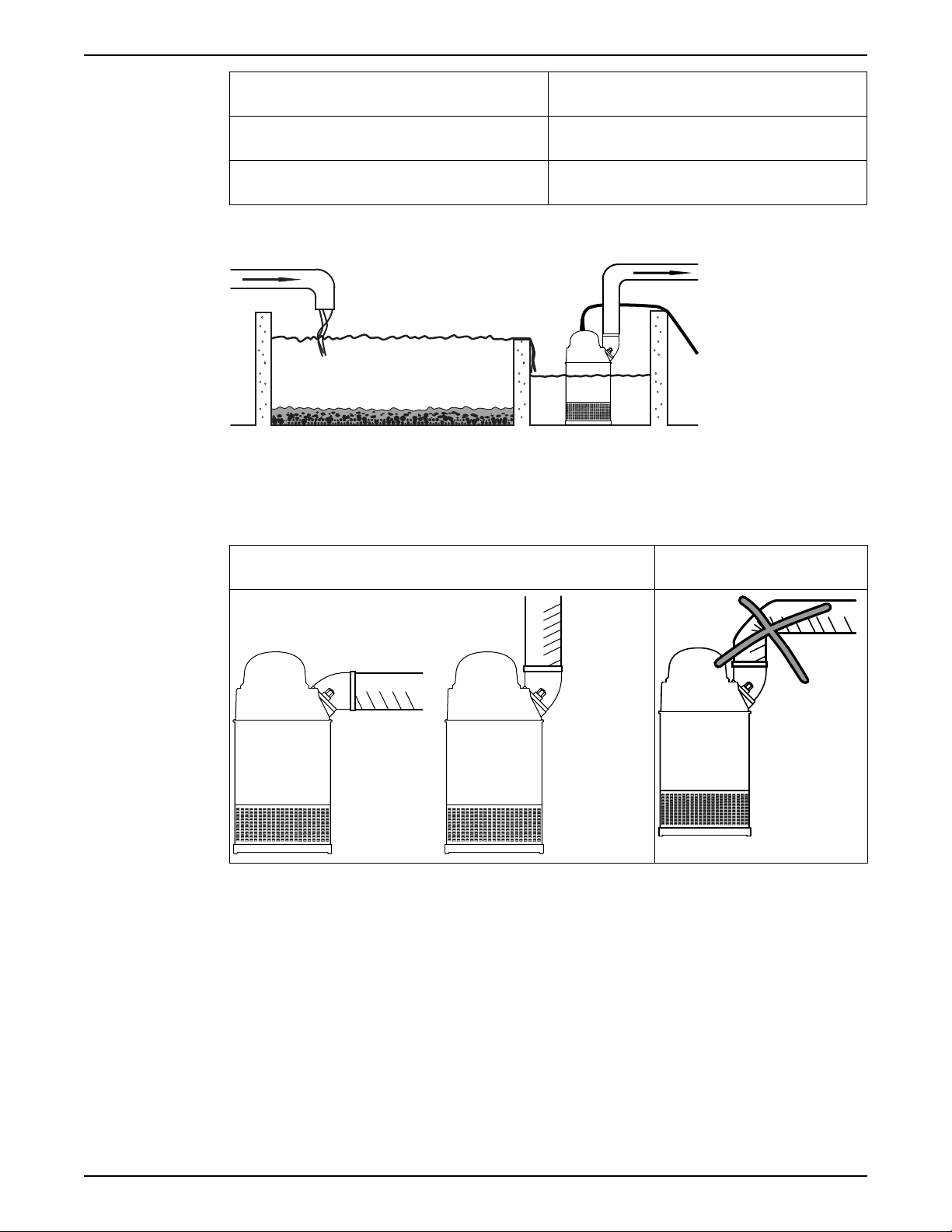
For more permanent installations with a heavily contaminated pumped liquid, a
settling pump-sump is recommended.
Figure 2: Settling pump-sump
Discharge line requirements
The discharge line can be run vertically or horizontally, but must be without
sharp bends.
Proper horizontal and vertical installation Improper installation
2.5 (8.2)
1.5 (4.9)
with a sharp bend
Fasteners
• Only use fasteners of the correct size and material.
• Replace all corroded or damaged fasteners.
• Make sure that all the fasteners are correctly tightened and that there are no
missing fasteners.
4.1.1 Install
The pump is transportable and intended to operate either completely or partially
submerged in the pumped liquid. The pump is equipped with a connection for
hose or pipe.
These requirements and instructions only apply when the installation is made
according to the dimensional drawing.
8125.230 Milli Installation, Operation, and Maintenance 13
Page 16
Equipment
locked out by
Name .......................
DANGER
4 Installation
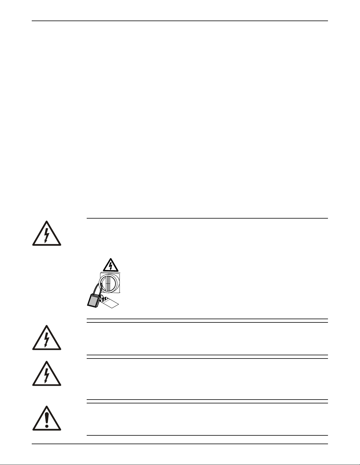
1. Run the cable so that it has no sharp bends, is not pinched, and cannot be
sucked into the pump inlet.
2. Connect the discharge line.
The discharge line can be run vertically or horizontally, but must be without
sharp bends.
3. Lower the pump into the sump.
The cable must not be used for this purpose. You should attach a rope or
similar to the handle or the eye bolts for lowering and lifting the pump.
Heavier pumps must be lifted and lowered down by crane. Suspend the pump
by the lifting handle or the eye bolts with chains or wires.
4. Place the pump on the base and make sure it cannot fall over or sink.
The base should consist of a plank, a bed of coarse gravel, or a cut-down and
perforated oil drum.
Alternatively, the pump can be suspended with a lifting chain just above the
sump bottom. Make sure that the pump cannot rotate at start-up or during
operation.
5. Connect the motor cable and the starter and monitoring equipment according
to the separate instructions.
Make sure that the impeller rotation is correct. For more information, see
Check the impeller rotation on page 18.
4.2 Make the electrical connections
General precautions
DANGER: Electrical Hazard
Before starting work on the unit, make sure that the unit and the control panel
are isolated from the power supply and cannot be energized. This applies to the
control circuit as well.
WARNING: Electrical Hazard
Risk of electrical shock or burn. A certified electrician must supervise all
electrical work. Comply with all local codes and regulations.
WARNING: Electrical Hazard
There is a risk of electrical shock or explosion if the electrical connections are not
correctly carried out, or if there is fault or damage on the product. Visually
inspect equipment for damaged cables, cracked casings or other signs of
damage. Make sure that electrical connections have been correctly made.
WARNING: Crush Hazard
Risk of automatic restart.
14 8125.230 Milli Installation, Operation, and Maintenance
Page 17

Requirements
4 Installation
CAUTION: Electrical Hazard
Prevent cables from becoming sharply bent or damaged.
NOTICE:
Leakage into the electrical parts can cause damaged equipment or a blown fuse.
Keep the cable ends dry at all times.
These general requirements apply for electrical installation:
• The supply authority must be notified before installing the pump if it will be
connected to the public mains. When the pump is connected to the public
power supply, it may cause flickering of incandescent lamps when started.
• The mains voltage and frequency must agree with the specifications on the
data plate. If the pump can be connected to different voltages, then the
connected voltage is specified by a yellow sticker close to the cable entry.
• The fuses and circuit breakers must have the proper rating, and the pump
overload protection (motor protection breaker) must be connected and set to
the rated current according to the data plate and if applicable the cable chart.
The starting current in direct-on-line start can be up to six times higher than
the rated current.
• The fuse rating and the cables must be in accordance with the local rules and
regulations.
• If intermittent operation is prescribed, then the pump must be provided with
monitoring equipment supporting such operation.
• The thermal contacts/thermistors must be in use.
Cables
These are the requirements to follow when you install cables:
• The cables must be in good condition, not have any sharp bends, and not be
pinched.
• The cables must not be damaged and must not have indentations or be
embossed (with markings, etc.) at the cable entry.
• The minimum bending radius must not be below the accepted value.
• If using a cable which has been used before, a short piece must be peeled off
when refitting it so that the cable entry seal sleeve does not close around the
cable at the same point again. If the outer sheath of the cable is damaged,
then replace the cable.
Contact a sales or authorized service representative.
• The voltage drop in long cables must be taken into account. The drive unit’s
rated voltage is the voltage measured at the cable connection point in the
pump.
• For SUBCAB® cables, the twisted pair copper foil must be trimmed.
• All unused conductors must be insulated.
Grounding (earthing)
Grounding (earthing) must be done in compliance with all local codes and
regulations.
DANGER: Electrical Hazard
All electrical equipment must be grounded (earthed). Test the ground (earth)
lead to verify that it is connected correctly and that the path to ground is
continuous.
8125.230 Milli Installation, Operation, and Maintenance 15
Page 18
WS001396B
4 Installation
WARNING: Electrical Hazard
If the power cable is jerked loose, then the ground (earth) conductor must be
the last conductor to come loose from its terminal. Make sure that the ground
(earth) conductor is longer than the phase conductors at both ends of the cable.
WARNING: Electrical Hazard
Risk of electrical shock or burn. You must connect an additional ground- (earth-)
fault protection device to the grounded (earthed) connectors if persons are likely
to come into contact with liquids that are also in contact with the pump or
pumped liquid.
Ground (earth) conductor length
The ground (earth) conductor must be 180 mm (7.1 in) longer than the phase
conductors in the junction box of the unit.
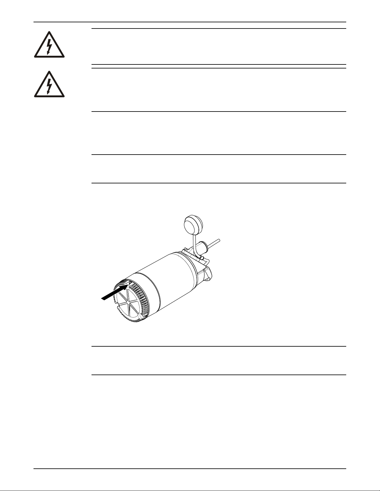
Check the ground (earth) continuity
NOTICE:
The two earth (ground) conductors in the pump are connected via the same
conductor to ground (earth)
Check the ground (earth) continuity.
Measure between the ground (earth) conductor in the motor cable and one of
the screws securing the strainer.
4.2.1 Connect the motor cable to the pump
NOTICE:
Leakage into the electrical parts can cause damaged equipment or a blown fuse.
Keep the end of the motor cable dry at all times.
1. Check the data plate to see which connections are required for the power
supply.
2. Connect the motor cable conductors, including ground (earth) , to the
terminal or starter unit.
3. Make sure that the pump is correctly connected to ground (earth) .
4. Firmly tighten the cable entry into its bottom-most position.
The seal sleeve and the washers must conform to the outside diameter of the
cables.
16 8125.230 Milli Installation, Operation, and Maintenance
Page 19
DANGER: Explosion/Fire Hazard
WS001021B
L1 L2 L3
T3 T4T1 T2
15
13
14
42 31
7
10
5
9
8
6
11
12
17
16
24
22
23
19
20
21
18
Special rules apply to installations in explosive or flammable atmospheres. Do
not install the product or any auxiliary equipment in an explosive zone unless it
is rated explosion-proof or intrinsically-safe. If the product is EN/ATEX-, MSHAor FM-approved, then see the specific EX information in the Safety chapter
before taking any further actions.
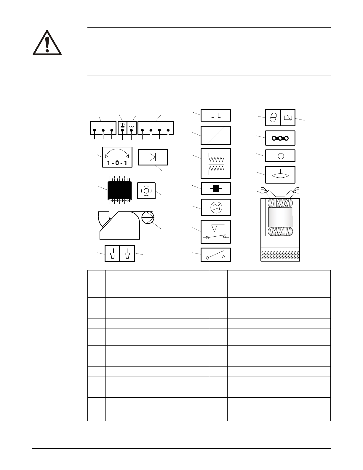
4.2.2 Cable charts
Connection locations
4 Installation
1 Starter equipment and main
13 Coil
leads (L1, L2, L3)
2 Ground (earth) 14 Transformer
3 Functional ground 15 Capacitor
4 Control leads (T1, T2, T3, T4) 16 Softstarter
5 Phase shifter 17 Level regulator
6 Diode 18 Contactor, start relay or thermal
relay
7 Motor cable 19 Thermal detector in stator
8 Screen 20 Thermal detector in main bearing
9 Pump 21 Jumper
10 Crimp connection 22 Terminal board, terminal plate
11 Crimp isolation 23 Leakage sensor
12 Motor protector 24 Stator leads (U1, U2, U5, U6, V1,
V2, V5, V6, W1, W2, W5, W6,
Z1, Z5, Z6)
8125.230 Milli Installation, Operation, and Maintenance 17
Page 20
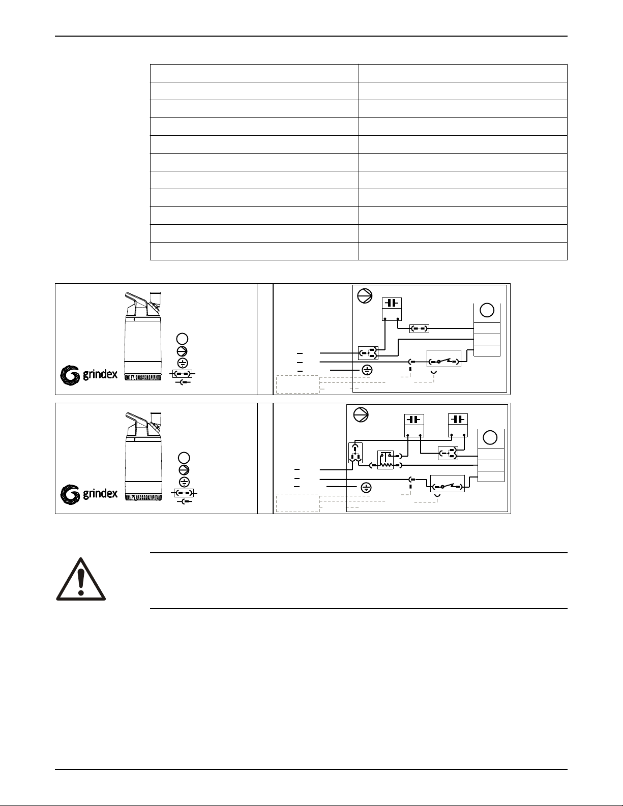
1 - P H A S E (1~)
788 24 01
8121
8122
8123
Connection plate
BN
BU
GNYE
Motor cable
Pump
Capacitor
WH
WH
Stator
WH
BN
BK
With capacitor
COLOUR STANDARD
AND SYMBOLS
BN=Brown
BK=Black
BU=Blue
WH=White
GNYE=Green-Yellow
1 - P H A S E (1~)
BN
BU
GNYE
Motor cable
Pump
start
Capacitor
Motorswitch
run
Capacitor
WH
Relay
2
3
4
788 24 01
8121
8122
8123
Connection plate
WH
BN
BK
With start
and run capacitor
M
M
M
Ground
Motorswitch
3
1
Terminal device
230V/50Hz
115V-240V/50Hz
115V-230V/60Hz
Float switch
Optional
GC
GNYE
GC
Ground check
BN/BK
BU/WH
Float switch
Optional
GC
GNYE
BN/BK
BU/WH
WH
WH
3
1
WH
WH
Connector
Inside pump
Stator
COLOUR STANDARD
AND SYMBOLS
BN=Brown
BK=Black
BU=Blue
WH=White
GNYE=Green-Yellow
M
Ground
Terminal device
GC
Ground check
Connector
Inside pump
BU
BU
WS007752
8125
8125
4 Installation
Color code standard
Code Description
BN Brown
BK Black
WH White
OG Orange
GN Green
GNYE Green-Yellow
RD Red
GY Grey
BU Blue
YE Yellow
Motor cable and starter unit connection to the terminal board
4.3 Check the impeller rotation
CAUTION: Crush Hazard
The starting jerk can be powerful. Make sure nobody is close to the unit when it
is started.
Check the direction of rotation each time the cable has been re-connected and
after phase or total supply failure.
1. Start the motor.
2. Stop the motor.
3. Check that the impeller rotates in the correct direction.
18 8125.230 Milli Installation, Operation, and Maintenance
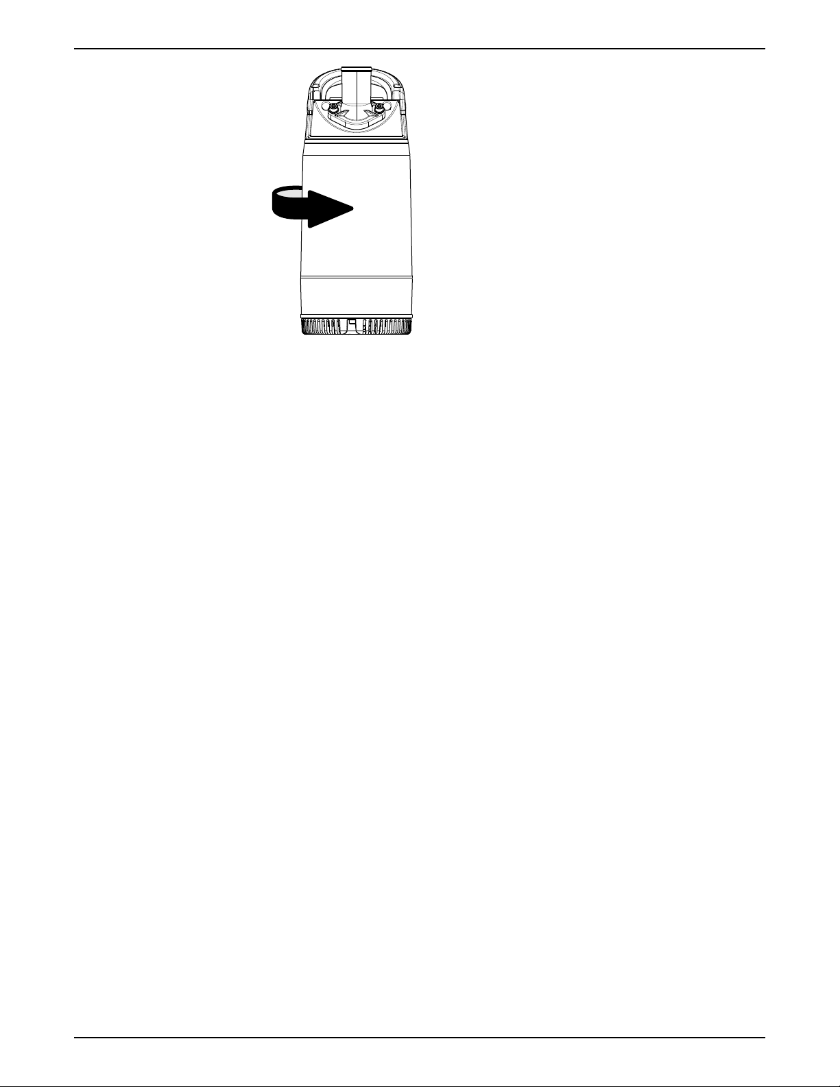
The correct direction of impeller rotation is clockwise when you look at the
pump from above. When started, the pump will react in the opposite direction
to the impeller rotation.
Page 21
WS001398B
4 Installation
Figure 3: Start reaction
4. If the impeller rotates in the wrong direction, then do the following:
– If the motor has a 1-phase connection, then contact a sales or authorized
service representative.
8125.230 Milli Installation, Operation, and Maintenance 19
Page 22
5 Operation
5 Operation
5.1 Precautions
Before taking the unit into operation, check the following:
• All recommended safety devices are installed.
• The cable and cable entry have not been damaged.
• All debris and waste material has been removed.
NOTICE:
Never operate the pump with the discharge line blocked, or the discharge valve
closed.
WARNING: Crush Hazard
Risk of automatic restart.
Distance to wet areas
WARNING: Electrical Hazard
Risk of electrical shock or burn. You must connect an additional ground- (earth-)
fault protection device to the grounded (earthed) connectors if persons are likely
to come into contact with liquids that are also in contact with the pump or
pumped liquid.
CAUTION: Electrical Hazard
Risk of electrical shock or burn. The equipment manufacturer has not evaluated
this unit for use in swimming pools. If used in connection with swimming pools
then special safety regulations apply.
Noise level
NOTICE:
The sound power level of the product is lower than 70 dB(A). However, in some
installations the resulting sound pressure level may exceed 70 dB(A) at certain
operating points on the performance curve. Make sure that you understand the
noise level requirements in the environment where the product is installed.
Failure to do so may result in hearing loss or violation of local laws.
Single phase pumps
WARNING: Explosion/Fire Hazard
The start capacitor is not designed for many repeated start cycles in a short
time. Always wait at least 15 seconds between starting attempts. Maximum
allowed: 30 starts per hour.
5.2 Start the pump
CAUTION: Crush Hazard
The starting jerk can be powerful. Make sure nobody is close to the unit when it
is started.
20 8125.230 Milli Installation, Operation, and Maintenance
Page 23
WS008618A
5 Operation
NOTICE:
Make sure that the rotation of the impeller is correct. For more information, see
Check the impeller rotation.
1. Inspect the pump. Check that there is no physical damage to the pump or
cables.
2. Check the oil level in the oil housing.
3. Remove the fuses or open the circuit breaker, and check that the impeller can
rotate freely.
WARNING: Crush Hazard
Never put your hand into the pump housing.
4. Check that the monitoring equipment (if any) works.
5. Check that the impeller rotation is correct.
6. Check the water level.
If the water level is too low, then fill the pump with water according to the
instruction Fill with water on page 21.
7. Start the pump.
5.2.1 Fill with water
If the water level in the pump is too low, then the pump cannot start. The pump
has a built-in check valve that enables the pump to be manually filled with water.
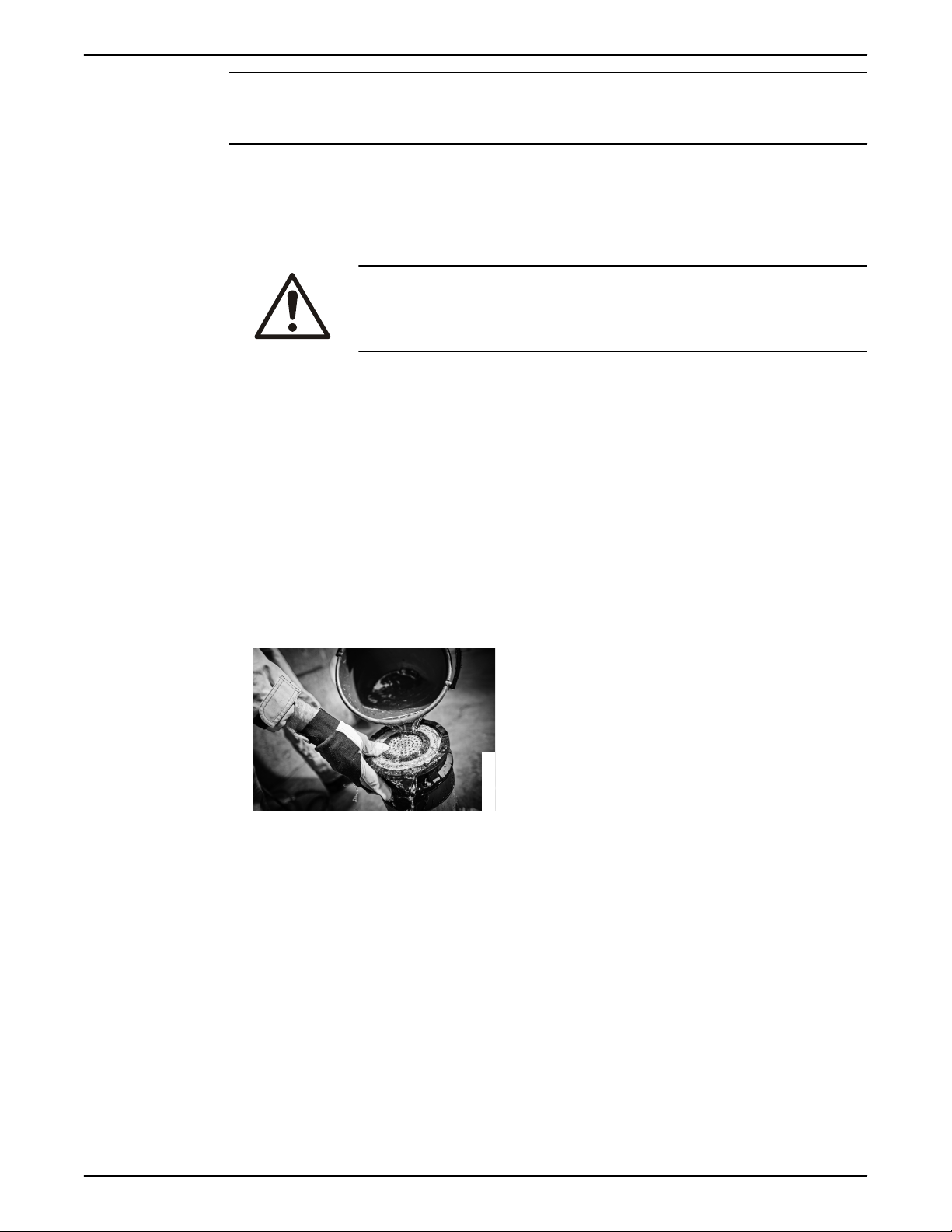
1. Turn the pump over and stabilize it.
2. Fill the pump with water.
Quantity: 1.0 L (1.1 qt)
5.3 Clean the pump
The pump must be cleaned if it has been running in very dirty water. If clay,
cement or other similar dirt is left in the pump it may clog the impeller and seal,
preventing the pump from working.
Let the pump run for a while in clean water, or flush it through the discharge
connection.
8125.230 Milli Installation, Operation, and Maintenance 21
Page 24
Equipment
locked out by
Name .......................
DANGER
6 Maintenance
6 Maintenance
Precautions
Before starting work, make sure that the safety instructions in the chapter
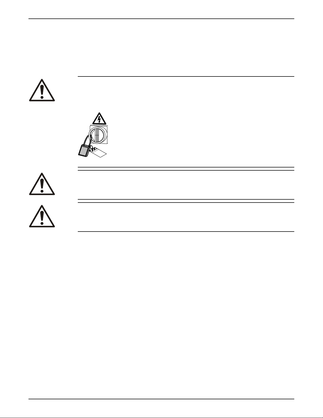
Introduction and Safety on page 3 have been read and understood.
DANGER: Crush Hazard
Moving parts can entangle or crush. Always disconnect and lock out power
before servicing to prevent unexpected startup. Failure to do so could result in
death or serious injury.
WARNING: Biological Hazard
Infection risk. Rinse the unit thoroughly with clean water before working on it.
CAUTION: Crush Hazard
Make sure that the unit cannot roll or fall over and injure people or damage
property.
Make sure that you follow these requirements:
• Check the explosion risk before you weld or use electrical hand tools.
• Allow all system and pump components to cool before you handle them.
• Make sure that the product and its components have been thoroughly
cleaned.
• Make sure that the work area is well-ventilated before you open any vent or
drain valves, remove any plugs, or disassemble the unit.
• Do not open any vent or drain valves or remove any plugs while the system is
pressurized. Make sure that the pump is isolated from the system and that
pressure is relieved before you disassemble the pump, remove plugs, or
disconnect piping.
Ground continuity verification
A ground (earth) continuity test must always be performed after service.
Maintenance guidelines
During the maintenance and before reassembly, always remember to perform
these tasks:
• Clean all parts thoroughly, particularly O-ring grooves.
• Change all O-rings, gaskets, and seal washers.
• Lubricate all springs, screws, O-rings with grease.
During the reassembly, always make sure that existing index markings are in
line.
22 8125.230 Milli Installation, Operation, and Maintenance
Page 25

The reassembled drive unit must always be insulation-tested and the
reassembled pump must always be test-run before normal operation.
6.1 Torque values
All screws and nuts must be lubricated to achieve correct tightening torque.
Screws that are screwed into stainless steel must have the threads coated with
suitable lubricants to prevent seizing.
If there is a question regarding the tightening torques, then contact a sales or
authorized service representative.
Screws and nuts
Table 1: Stainless steel, A2 and A4, torque Nm (ft-lbs)
6 Maintenance
Propert
y class
50 1.0
70, 80 2.7 (2) 5.4 (4) 9.0
100 4.1 (3) 8.1 (6) 14 (10) 34 (25) 66 (49) 115
Table 2: Steel, torque Nm (ft-lbs)
Propert
y class
8.8 2.9
10.9 4.0
12.9 4.9
Hexagon screws with countersunk heads
M4 M5 M6 M8 M10 M12 M16 M20 M24 M30
2.0
(0.74)
M4 M5 M6 M8 M10 M12 M16 M20 M24 M30
(2.1)
(2.9)
(3.6)
(1.5)
5.7
(4.2)
8.1 (6) 14 (10) 33 (24) 65 (48) 114
9.7
(7.2)
For hexagon socket head screws with countersunk head, maximum torque for all
property classes must be 80% of the values for property class 8.8 above.
3.0
(2.2)
(6.6)
9.8
(7.2)
17 (13) 40 (30) 79 (58) 136
8.0
(5.9)
22 (16) 44 (32) 76 (56) 187
24 (18) 47 (35) 81(60) 194
15 (11) 27 (20) 65 (48) 127
(84.8)
(84)
(100)
(138)
248
(183)
(143)
277
(204)
333
(245)
(93.7)
364
(268)
481
(355)
385
(285)
541
(399)
649
(480)
220
(162)
629
(464)
— —
665
(490)
935
(689)
1120
(825.1)
434
(320)
1240
(915)
1310
(966.2)
1840
(1357)
2210
(1630)
6.2 Service
Regular service of the pump ensures more reliable operation.
Inspection
The pump should be inspected at least twice a year, more frequently under
severe operating conditions.
Screw tightening
During assembly or service of the pumps we recommend that the screws be
tightened to approximately 6–8 Nm (4.5–6 ft-lbs). The tightening torque ensures
that the parts are correctly fastened and that the pumps will operate as
intended.
NOTICE:
Make sure that the oil-plug and securing screws for the strainer or the pump
housing are not tightened too hard.
8125.230 Milli Installation, Operation, and Maintenance 23
Page 26
WS002100A
6 Maintenance
To maintain screw tightness, use some mineral oil on all non-stainless steel
screws.
When using stainless steel screws on stainless steel parts, apply Aral Degol
GS 460 or National Chemseal Thread-Eze lubricant in order to prevent the
screws from seizing.
6.3 Change the oil
A paraffin oil with viscosity close to ISO VG32 is recommended. The pump is
delivered from the factory with this type of oil. Examples of suitable oil types are
the following:
• Statoil MedicWay 32
• BP Enerpar M 004
• Shell Ondina 927
• Shell Ondina X430
In applications where poisonous properties are of less concern, a mineral oil with
viscosity up to ISO VG32 can be used.
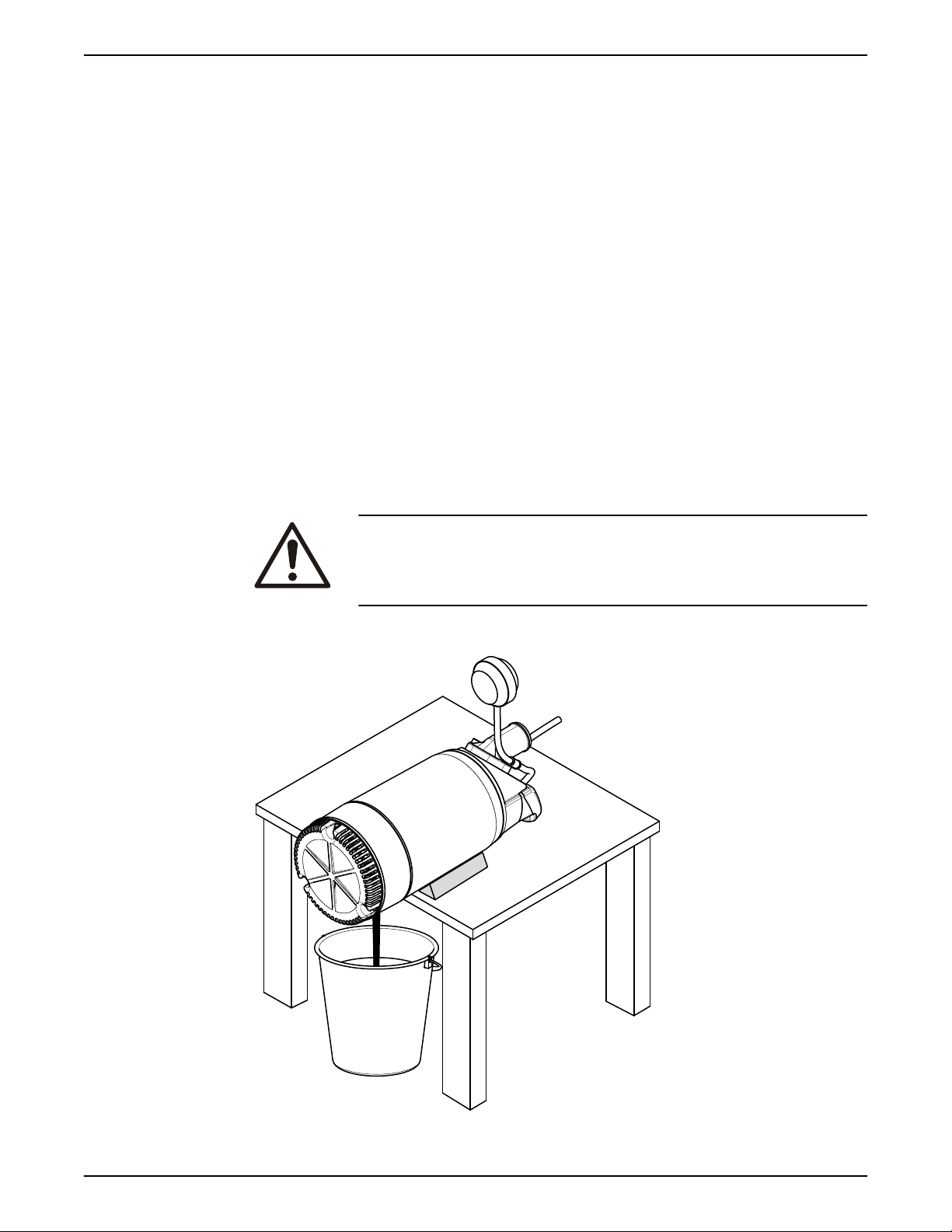
Empty the oil
1. Lay the pump on its side.
Lock the pump with supports to prevent it from rolling over.
2. Remove the oil screw.
™
™
™
™
CAUTION: Compressed Gas Hazard
Air inside the chamber may cause parts or liquid to be propelled
with force. Be careful when opening. Allow the chamber to depressurize before removal of the plug.
3. Turn the pump so that the oil hole faces downwards and let the oil run out
into a container.
24 8125.230 Milli Installation, Operation, and Maintenance
Page 27
Fill with oil
3x
WS008405A
1. Replace the oil screw O-ring.
2. Turn the pump so that the oil hole faces upwards and fill with new oil.
Quantity: 0.17 L (0.18 qt)
3. Put the oil screw back and tighten it.
6.4 Replace the impeller
6.4.1 Remove the impeller
CAUTION: Cutting Hazard
Worn parts can have sharp edges. Wear protective clothing.
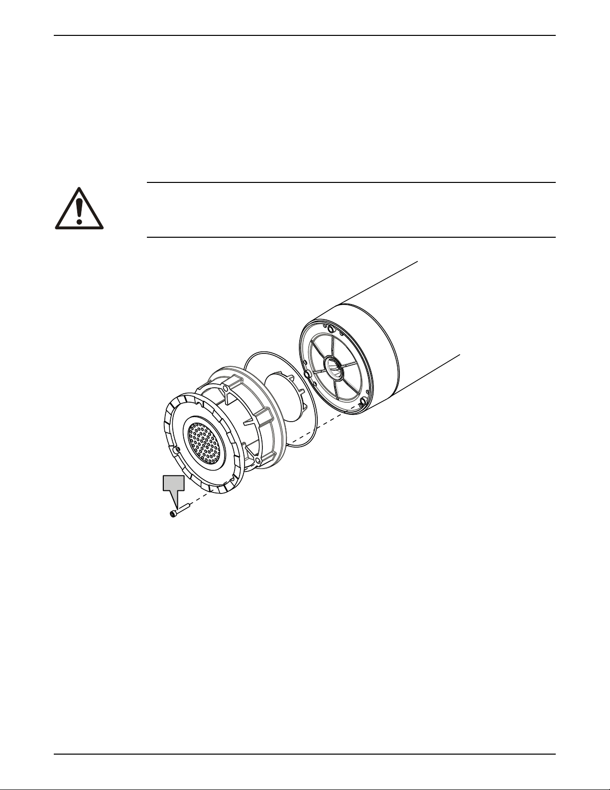
1. Remove the strainer.
6 Maintenance
2. Remove the diffuser.
8125.230 Milli Installation, Operation, and Maintenance 25
Page 28
WS002032A
WS002033A
6 Maintenance
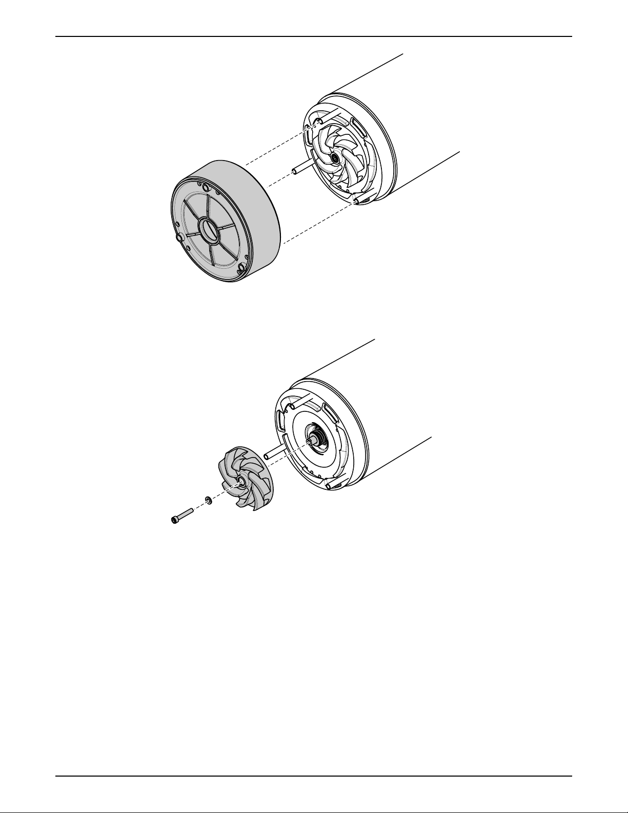
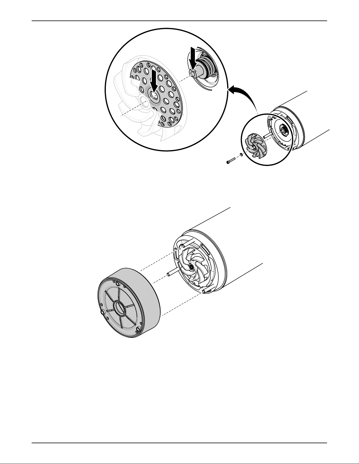
3. Remove the impeller:
a) Remove the impeller screw and washer.
b) Pull off the impeller.
6.4.2 Install the impeller
1. Prepare the shaft. Polish off any flaws with a fine emery cloth.
The end of the shaft must be clean and free from burrs.
2. Check that the impeller screw is clean and easy to screw into the shaft end.
This is to prevent the shaft from rotating with the impeller screw.
3. Fasten the impeller:
a) Place the washer on the impeller screw.
b) Mount the impeller.
Make sure that the impeller hub disk center is aligned with the slotted
shaft end.
26 8125.230 Milli Installation, Operation, and Maintenance
Page 29
WS002034A
c) Tighten the impeller screw.
WS002032A
Tightening torque: 9.3 Nm (6.9 ft-lb)
d) Check that the impeller can rotate freely.
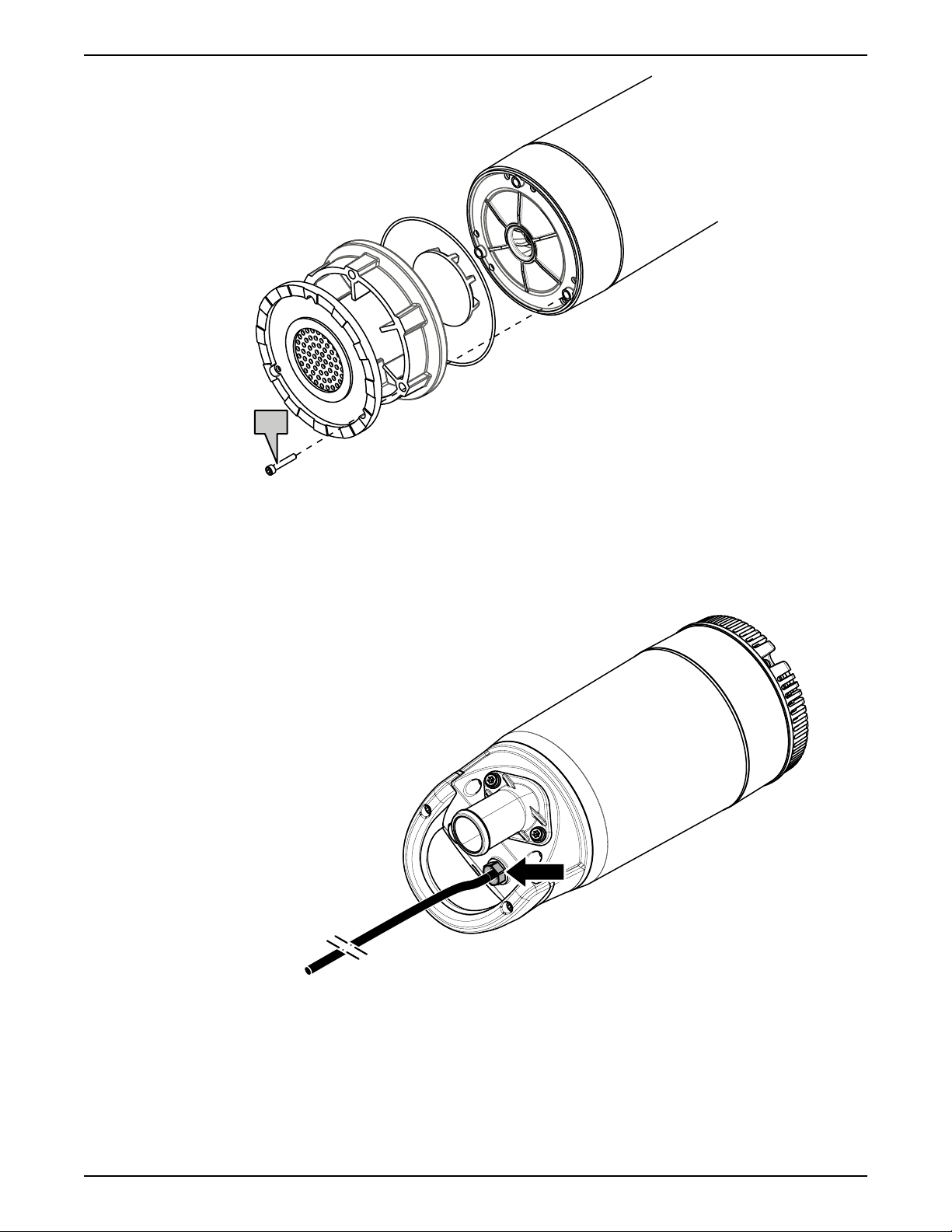
4. Mount the diffuser unit.
6 Maintenance
5. Mount the strainer and the screws.
Tightening torque: 9.3 Nm (6.9 ft-lb)
8125.230 Milli Installation, Operation, and Maintenance 27
Page 30
3x
WS008405A
WS003053A
6 Maintenance
6.5 Replace the motor cable
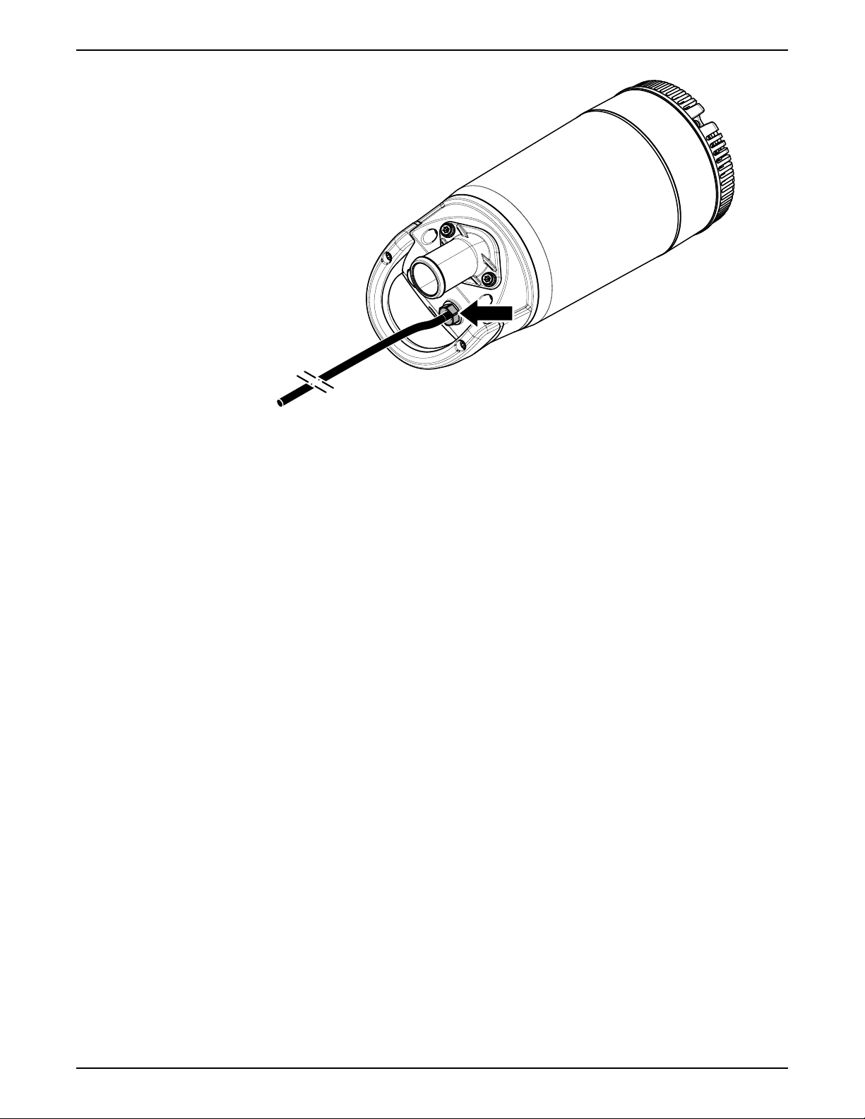
6.5.1 Remove the motor cable
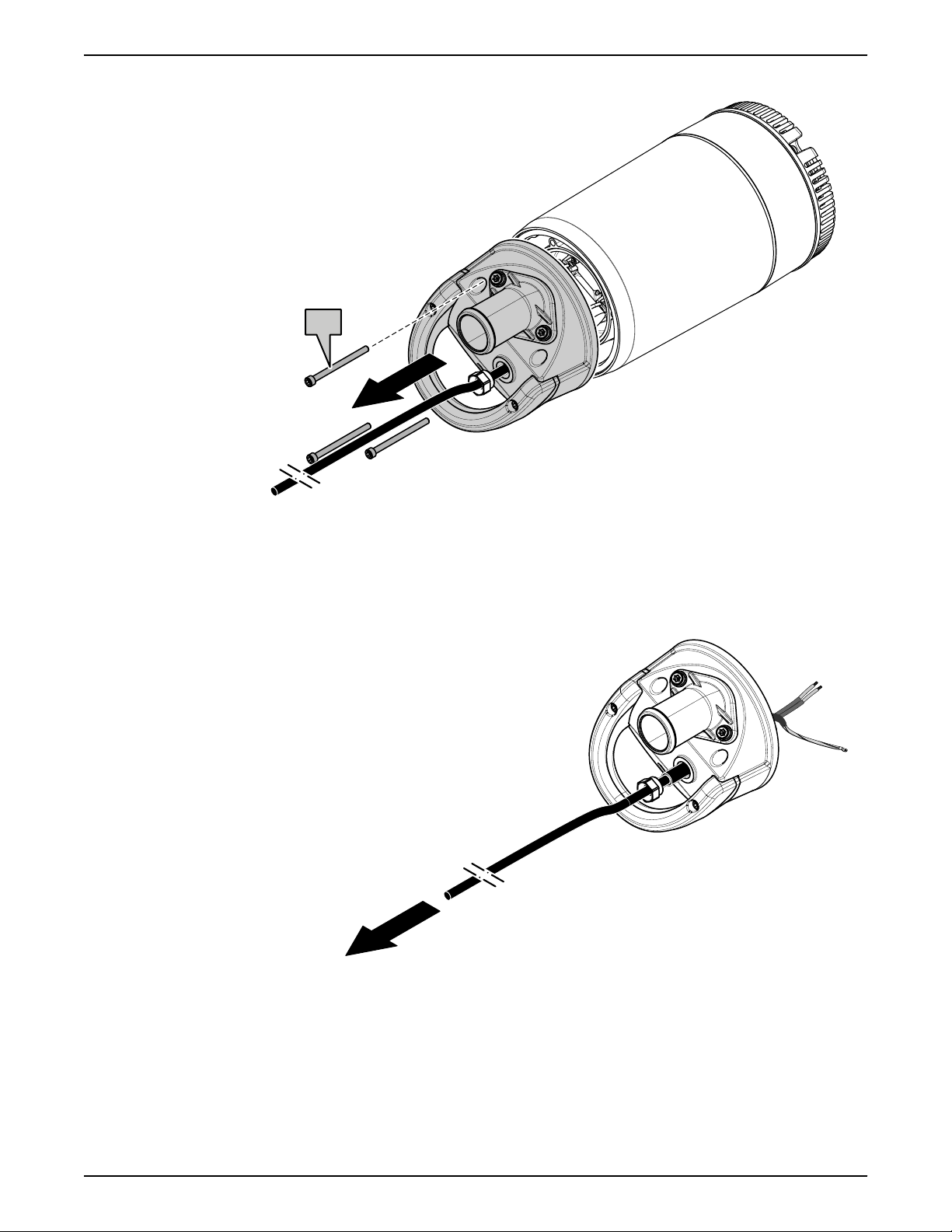
1. Loosen the cable entry.
2. Remove the pump top.
28 8125.230 Milli Installation, Operation, and Maintenance
Page 31
3x
WS003054A
WS003055A
6 Maintenance
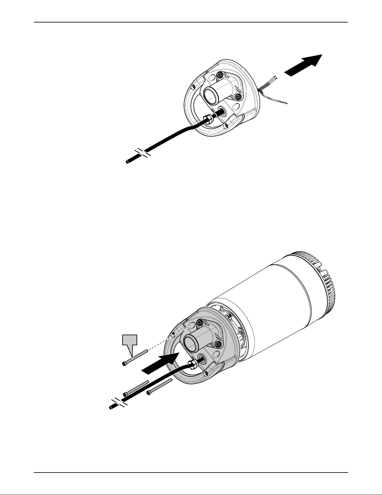
3. Disconnect the motor cable from the terminals:
a) Disconnect the power lead(s).
b) Disconnect the ground (earth) lead(s).
4. Remove the motor cable.
6.5.2 Install the motor cable
8125.230 Milli Installation, Operation, and Maintenance 29
1. Pull the cable through the pump top.
Page 32
WS003057A
3x
WS003056A
6 Maintenance
2. Connect the terminals. See Make the electrical connections on page 14.
If the cable is damaged, then cut off the damaged part and install new
terminals.
a) Connect the ground (earth) lead(s).
b) Connect the power lead(s).
3. Install the pump top.
4. Tighten the cable entry.
Make sure that it bottoms out.
30 8125.230 Milli Installation, Operation, and Maintenance
Page 33
WS003053A
6 Maintenance
8125.230 Milli Installation, Operation, and Maintenance 31
Page 34
Equipment
locked out by
Name .......................
DANGER
7 Troubleshooting
7 Troubleshooting
Introduction
DANGER: Electrical Hazard
Troubleshooting a live control panel exposes personnel to hazardous voltages.
Electrical troubleshooting must be done by a qualified electrician.
Follow these guidelines when troubleshooting:
• Disconnect and lock out the power supply except when conducting checks
that require voltage.
• Make sure that no one is near the unit when the power supply is reconnected.
• When troubleshooting electrical equipment, use the following:
– Universal instrument multimeter
– Test lamp (continuity tester)
– Wiring diagram
7.1 The pump does not start
DANGER: Crush Hazard
Moving parts can entangle or crush. Always disconnect and lock out power
before servicing to prevent unexpected startup. Failure to do so could result in
death or serious injury.
NOTICE:
Do NOT override the motor protection repeatedly if it has tripped. Doing so may
result in equipment damage.
Cause Remedy
An alarm signal has been
triggered on the control
panel.
Check that:
• The impeller rotates freely.
• The sensor indicators do not indicate an alarm.
• The overload protection is not tripped.
The pump does not start
automatically, but can be
started manually.
Check that:
• The start level regulator is functioning. Clean or
replace if necessary.
• All connections are intact.
• The relay and contactor coils are intact.
• The control switch (Man/Auto) makes contact in
both positions.
Check the control circuit and functions.
32 8125.230 Milli Installation, Operation, and Maintenance
Page 35
Cause Remedy
Equipment
locked out by
Name .......................
DANGER
7 Troubleshooting
The installation is not
receiving voltage.
Check that:
• The main power switch is on.
• There is control voltage to the start equipment.
• The fuses are intact.
• There is voltage in all phases of the supply line.
• All fuses have power and that they are securely
fastened to the fuse holders.
• The overload protection is not tripped.
• The motor cable is not damaged.
The impeller is stuck. Clean:
• The impeller
• The sump in order to prevent the impeller from
clogging again.
If the problem persists, then contact a sales or authorized service
representative.
Always state the product number and the serial number of the pump, see
Product Description on page 9.
7.2 The pump does not stop when a level sensor is used
DANGER: Crush Hazard
Moving parts can entangle or crush. Always disconnect and lock out power
before servicing to prevent unexpected startup. Failure to do so could result in
death or serious injury.
Cause Remedy
The pump is unable to
empty the sump to the
stop level.
Check that:
• There are no leaks from the piping and/or
discharge connection.
• The impeller is not clogged.
• The non-return valve(s) are functioning properly.
• The pump has adequate capacity. For
information:
Contact a sales or authorized service
representative.
There is a malfunction in
the level-sensing
equipment.
• Clean the level regulators.
• Check the functioning of the level regulators.
• Check the contactor and the control circuit.
• Replace all defective items.
The stop level is set too
Raise the stop level.
low.
8125.230 Milli Installation, Operation, and Maintenance 33
Page 36
Equipment
locked out by
Name .......................
DANGER
7 Troubleshooting
If the problem persists, then contact a sales or authorized service
representative.
Always state the product number and the serial number of the pump, see
Product Description on page 9.
7.3 The pump starts-stops-starts in rapid sequence
Cause Remedy
The pump starts due to
back-flow which fills the
sump to the start level
again.
Check that:
• The distance between the start and stop levels is
sufficient.
• The non-return valve(s) work(s) properly.
• The length of the discharge pipe between the
pump and the first non-return valve is sufficiently
short.
The self-holding function
of the contactor
malfunctions.
Check:
• The contactor connections.
• The voltage in the control circuit in relation to the
rated voltages on the coil.
• The functioning of the stop-level regulator.
• Whether the voltage drop in the line at the
starting surge causes the contactor's self-holding
malfunction.
If the problem persists, then contact a sales or authorized service
representative.
Always state the product number and the serial number of the pump, see
Product Description on page 9.
7.4 The pump runs but the motor protection trips
DANGER: Crush Hazard
Moving parts can entangle or crush. Always disconnect and lock out power
before servicing to prevent unexpected startup. Failure to do so could result in
death or serious injury.
NOTICE:
Do NOT override the motor protection repeatedly if it has tripped. Doing so may
result in equipment damage.
Cause Remedy
The motor protection is
set too low.
34 8125.230 Milli Installation, Operation, and Maintenance
Set the motor protection according to the data plate
and if applicable the cable chart.
Page 37
Cause Remedy
Equipment
locked out by
Name .......................
DANGER
7 Troubleshooting
The impeller is difficult to
rotate by hand.
The drive unit is not
receiving full voltage on
all three phases.
The phase currents vary,
or they are too high.
The insulation between
the phases and ground in
the stator is defective.
The density of the
pumped fluid is too high.
The ambient temperature
exceeds the maximum
ambient temperature.
• Clean the impeller.
• Clean out the sump.
• Check that the impeller is properly trimmed.
• Check the fuses. Replace fuses that have tripped.
• If the fuses are intact, then notify a certified
electrician.
Contact a sales or authorized service representative.
1. Use an insulation tester. With a 1000 V DC
megger, check that the insulation between the
phases and between any phase and ground is >
5 megaohms.
2. If the insulation is less, then do the following:
Contact a sales or authorized service
representative.
Make sure that the maximum density is 1100 kg/m3
(9.2 lb/US gal)
• Change to a more suitable pump
• Contact a sales or authorized service
representative.
The pump must not be used for such an application.
There is a malfunction in
Replace the overload protection.
the overload protection.
If the problem persists, then contact a sales or authorized service
representative.
Always state the product number and the serial number of the pump, see
Product Description on page 9.
7.5 The pump delivers too little or no water
DANGER: Crush Hazard
Moving parts can entangle or crush. Always disconnect and lock out power
before servicing to prevent unexpected startup. Failure to do so could result in
death or serious injury.
NOTICE:
Do NOT override the motor protection repeatedly if it has tripped. Doing so may
result in equipment damage.
8125.230 Milli Installation, Operation, and Maintenance 35
Page 38
7 Troubleshooting
Cause Remedy
The impeller rotates in
the wrong direction.
• If it is a 1-phase pump, then do the following:
Contact a sales or authorized service
representative.
One or more of the valves
are set in the wrong
positions.
• Reset the valves that are set in the wrong
position.
• Replace the valves, if necessary.
• Check that all valves are correctly installed
according to media flow.
• Check that all valves open correctly.
The impeller is difficult to
rotate by hand.
• Clean the impeller.
• Clean out the sump.
• Check that the impeller is properly trimmed.
The pipes are obstructed. To ensure a free flow, clean out the pipes.
The pipes and joints leak. Find the leaks and seal them.
There are signs of wear
Replace the worn parts.
on the impeller, pump,
and casing.
The liquid level is too low. • Check that the level sensor is set correctly.
• Depending on the installation type, add a means
for priming the pump, such as a foot valve.
If the problem persists, then contact a sales or authorized service
representative.
Always state the product number and the serial number of the pump, see
Product Description on page 9.
36 8125.230 Milli Installation, Operation, and Maintenance
Page 39
8 Technical Reference
8.1 Application limits
Data Description
Media (liquid) temperature 5–35°C (41–95°F)
pH of the pumped media (liquid) 5–8
Media (liquid) density 1100 kg/m³ (9.2 lb per US gal)
Depth of immersion Maximum 5 m (16.5 ft)
Other For the specific weight, current,
8 Technical Reference
maximum
voltage, power ratings, and speed of
the pump, see the data plate of the
pump.
For other applications, contact a sales
or authorized service representative for
information.
8.2 Motor data
Feature Description
Motor type Squirrel-cage induction motor
Frequency 50 Hz or 60 Hz
Supply 1-phase
Maximum starts
per hour
Code compliance IEC 60034-1
Voltage variation
without
overheating
Voltage imbalance
tolerance
Stator insulation
class
Motor encapsulation
Motor encapsulation is in accordance with IP68.
8.3 Specific motor data
30 evenly-spaced starts per hour
±10%, if it does not run continuously at full load
2%
F (155°C [311°F])
1-phase, 50 Hz
Motor type:
• 2,760 rpm
• 420 W (0.5 hp)
Voltage (V) Rated current (A) Starting current (A)
115 5.1 19
8125.230 Milli Installation, Operation, and Maintenance 37
Page 40
WS008401A
A
B
8 Technical Reference
Voltage (V) Rated current (A) Starting current (A)
230 2.7 7.5
240 2.4 7.8
1-phase, 60 Hz
Motor type:
• 3,335 rpm
• 450 W (0.6 hp)
Voltage (V) Rated current (A) Starting current (A)
115 5.5 18
230 2.9 7
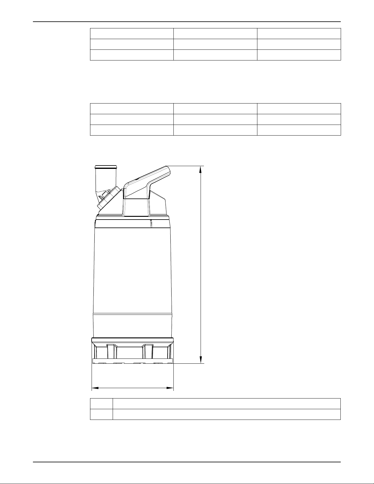
8.4 Dimensions and weights
A 459 mm (18.1 in)
B Ø190 mm (7.5 in)
Weight without motor cable: 13 kg (29 lb)
38 8125.230 Milli Installation, Operation, and Maintenance
Page 41
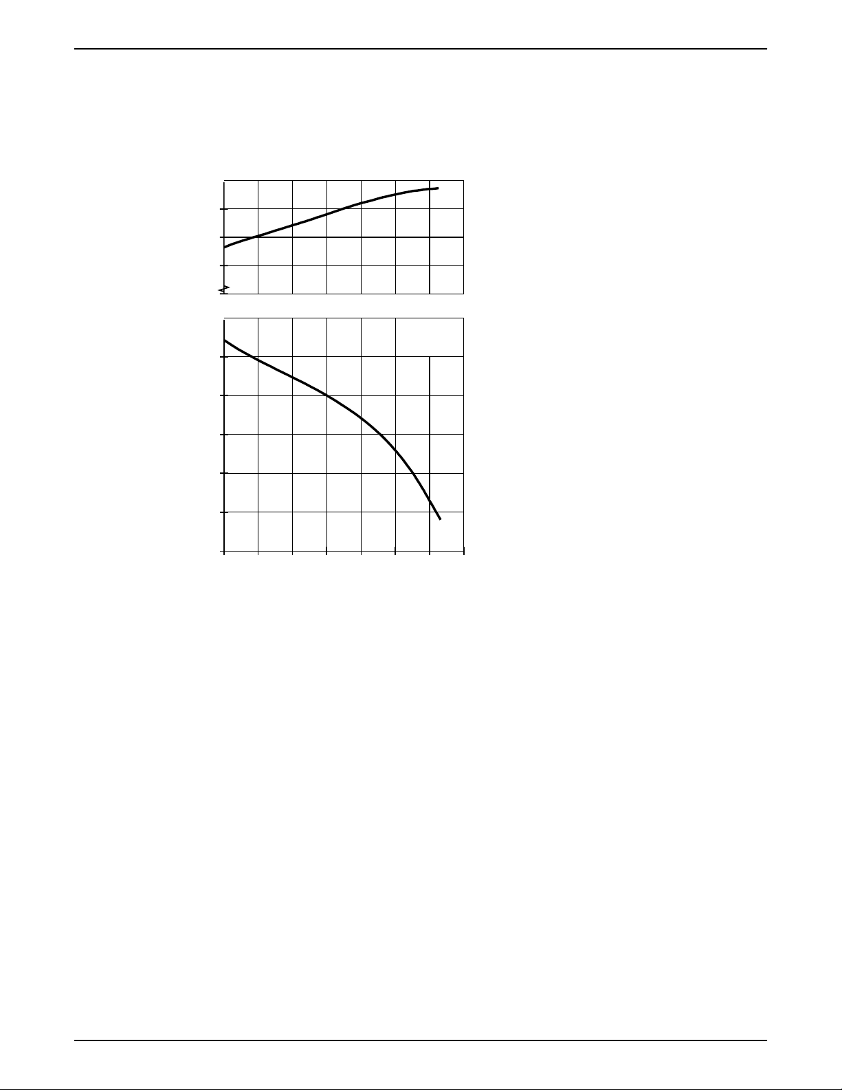
8.5 Performance curves
Q [l/s]
H [m]
1
P [kW]
0.0 0.5 1.0 1.5 2.0 2.5 3.0
0
2
4
6
8
10
0.3
0.4
0.5
MT
WS008784A
Test standard
Pumps are tested in accordance with ISO 9906:2012, HI 11.6:2012.
50 Hz
8 Technical Reference
8125.230 Milli Installation, Operation, and Maintenance 39
Page 42
Q [l/s]
H
[m]
1
P
[kW]
0.0 0.5 1.0 1.5 2.0 2.5
0
2
4
6
8
10
0.3
0.4
0.5
MT
WS008785A
8 Technical Reference
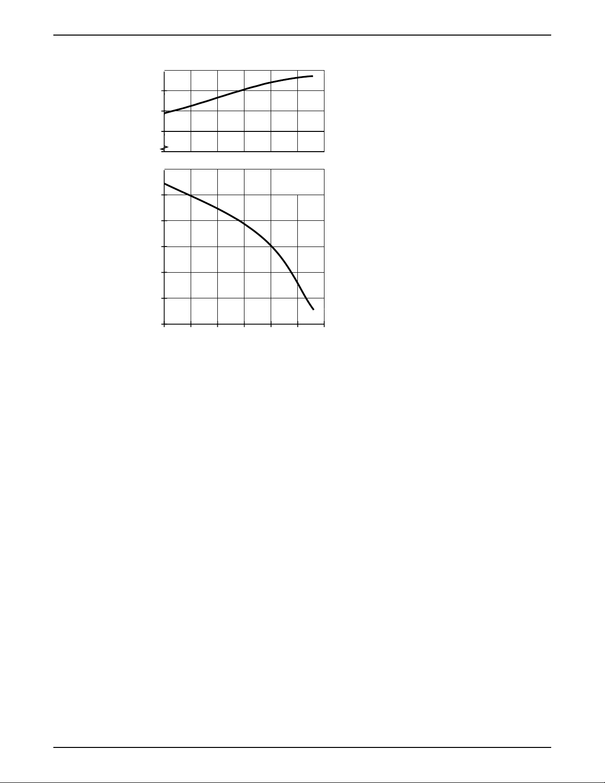
60 Hz
40 8125.230 Milli Installation, Operation, and Maintenance
Page 43

Page 44

www.grindex.com
Grindex
Gesällvägen 33
174 07 Sundbyberg
Sweden
Tel: +46-8-606 66 00
Fax: +46-8-745 53 28
www.grindex.com
885581_4.0_en-US_2017-10_IOM_8125.230 Milli
Visit our Web site for the latest version of this document
and more information
The original instruction is in English. All non-English
instructions are translations of the original instruction.
©
2014 Grindex
 Loading...