

Page 1
Revision 1.0
www.grindex.com
Installation, Operation, and Maintenance
Manual
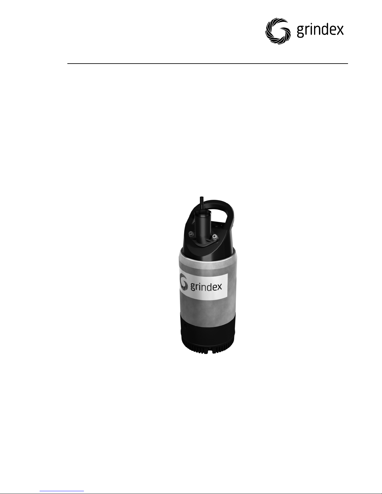
8122.210 Macro
Page 2

Page 3

Table of Contents
Introduction and Safety...............................................................................3
Introduction.................................................................................................3
Safety terminology and symbols.....................................................................3
Inspect the delivery......................................................................................4
Inspect the package....................................................................................4
Inspect the unit..........................................................................................4
Product warranty..........................................................................................4
Safety.........................................................................................................5
User safety..................................................................................................6
Hazardous liquids.......................................................................................6
Wash the skin and eyes...............................................................................6
Environmental safety....................................................................................7
Transportation and Storage.........................................................................8
Transportation guidelines...............................................................................8
Precautions................................................................................................8
Position and fastening.................................................................................8
Lifting.......................................................................................................8
Storage guidelines........................................................................................8
Storage location.........................................................................................8
Freezing precautions...................................................................................8
Long-term storage......................................................................................9
Table of Contents
Product Description...................................................................................10
Products included.......................................................................................10
Pump design..............................................................................................10
Monitoring equipment..................................................................................10
Level regulators........................................................................................10
The data plate............................................................................................11
Installation................................................................................................13
Install the pump.........................................................................................13
Sedimentation prevention..........................................................................13
Discharge line requirements.......................................................................13
Fasteners.................................................................................................14
Install.....................................................................................................14
Make the electrical connections.....................................................................15
General precautions..................................................................................15
Requirements...........................................................................................15
Cables.....................................................................................................16
Earthing (Grounding)................................................................................16
Electrical connection..................................................................................16
Check the impeller rotation..........................................................................17
Operation..................................................................................................19
Precautions................................................................................................19
Distance to wet areas..................................................................................19
Noise level.................................................................................................19
Start the pump...........................................................................................19
Clean the pump..........................................................................................20
8122.210 Macro Installation, Operation, and Maintenance Manual 1
Page 4

Table of Contents
Maintenance..............................................................................................21
Precautions................................................................................................21
Maintenance guidelines................................................................................21
Torque values.............................................................................................21
Service......................................................................................................22
Troubleshooting.........................................................................................23
Introduction...............................................................................................23
The pump does not start..............................................................................23
The pump does not stop when a level sensor is used.......................................24
The pump starts-stops-starts in rapid sequence..............................................24
The pump runs but the motor protection trips.................................................25
The pump delivers too little or no water.........................................................25
Technical Reference...................................................................................27
Application limits........................................................................................27
Motor data.................................................................................................27
Specific motor data.....................................................................................27
Dimensions and weights..............................................................................28
Performance curves....................................................................................28
2 8122.210 Macro Installation, Operation, and Maintenance Manual
Page 5
Introduction and Safety
Introduction
Purpose of this manual
The purpose of this manual is to provide necessary information for:
• Installation
• Operation
• Maintenance
CAUTION:
Read this manual carefully before installing and using the product. Improper use
of the product can cause personal injury and damage to property, and may void
the warranty.
NOTICE:
Save this manual for future reference, and keep it readily available at the location
of the unit.
Introduction and Safety
Safety terminology and symbols
About safety messages
It is extremely important that you read, understand, and follow the safety
messages and regulations carefully before handling the product. They are
published to help prevent these hazards:
• Personal accidents and health problems
• Damage to the product
• Product malfunction
Hazard levels
Hazard level Indication
DANGER:
WARNING:
CAUTION:
A hazardous situation which, if not
avoided, will result in death or serious
injury
A hazardous situation which, if not
avoided, could result in death or serious
injury
A hazardous situation which, if not
avoided, could result in minor or
moderate injury
8122.210 Macro Installation, Operation, and Maintenance Manual 3
Page 6
Introduction and Safety (Continued)
Hazard level Indication
NOTICE:
Hazard categories
Hazard categories can either fall under hazard levels or let specific symbols
replace the ordinary hazard level symbols.
Electrical hazards are indicated by the following specific symbol:
Electrical Hazard:
These are examples of other categories that can occur. They fall under the
ordinary hazard levels and may use complementing symbols:
• Crush hazard
• Cutting hazard
• Arc flash hazard
• A potential situation which, if not
avoided, could result in undesirable
conditions
• A practice not related to personal
injury
Inspect the delivery
Inspect the package
1. Inspect the package for damaged or missing items upon delivery.
2. Note any damaged or missing items on the receipt and freight bill.
3. File a claim with the shipping company if anything is out of order.
If the product has been picked up at a distributor, make a claim directly to the
distributor.
Inspect the unit
1. Remove packing materials from the product.
Dispose of all packing materials in accordance with local regulations.
2. Inspect the product to determine if any parts have been damaged or are
missing.
3. If applicable, unfasten the product by removing any screws, bolts, or straps.
For your personal safety, be careful when you handle nails and straps.
4. Contact your sales representative if anything is out of order.
Product warranty
Coverage
Grindex undertakes to remedy the following faults in products sold by Grindex
under the following conditions:
• The faults are due to defects in design, materials or workmanship.
• The faults are reported to an Grindex representative within the warranty
period.
• The product is used only under the conditions described in this manual.
• The monitoring equipment incorporated in the product is correctly connected
and in use.
4 8122.210 Macro Installation, Operation, and Maintenance Manual
Page 7
Limitations
Warranty claim
Spare parts
Introduction and Safety (Continued)
• All service and repair work is done by personnel authorized by Grindex.
• Genuine Grindex parts are used.
The warranty does not cover faults caused by the following:
• Deficient maintenance
• Improper installation
• Modifications or changes to the product and installation carried out without
consulting Grindex
• Incorrectly executed repair work
• Normal wear and tear
Grindex assumes no liability for the following:
• Bodily injuries
• Material damages
• Economic losses
Grindex products are high-quality products with expected reliable operation and
long life. However, should the need arise for a warranty claim, please contact
your Grindex representative.
Grindex guarantees that spare parts will be available for 10 years after the
manufacture of this product has been discontinued.
Safety
WARNING:
• The operator must be aware of safety precautions to prevent physical injury.
• Any pressure-containing device can explode, rupture, or discharge its
contents if it is over-pressurized. Take all necessary measures to avoid overpressurization.
• Operating, installing, or maintaining the unit in any way that is not covered in
this manual could cause death, serious personal injury, or damage to the
equipment. This includes any modification to the equipment or use of parts
not provided by Grindex. If there is a question regarding the intended use of
the equipment, please contact an Grindex representative before proceeding.
• Installation, Operation, and Maintenance manuals clearly identify accepted
methods for disassembling units. These methods must be adhered to.
Trapped liquid can rapidly expand and result in a violent explosion and injury.
Never apply heat to impellers, propellers, or their retaining devices to aid in
their removal.
CAUTION:
You must observe the instructions for installation, operation, and maintenance
contained in this manual. Failure to do so could result in physical injury, damage,
or delays.
8122.210 Macro Installation, Operation, and Maintenance Manual 5
Page 8

Introduction and Safety (Continued)
User safety
General safety rules
These safety rules apply:
• Always keep the work area clean.
• Pay attention to the risks presented by gas and vapors in the work area.
• Avoid all electrical dangers. Pay attention to the risks of electric shock or arc
flash hazards.
• Always bear in mind the risk of drowning, electrical accidents, and burn
injuries.
Safety equipment
Use safety equipment according to the company regulations. Use this safety
equipment within the work area:
• Helmet
• Safety goggles, preferably with side shields
• Protective shoes
• Protective gloves
• Gas mask
• Hearing protection
• First-aid kit
• Safety devices
NOTICE:
Never operate a unit unless safety devices are installed. Also see specific
information about safety devices in other chapters of this manual.
Electrical connections
Electrical connections must be made by certified electricians in compliance with
all international, national, state, and local regulations. For more information
about requirements, see sections dealing specifically with electrical connections.
Hazardous liquids
The product is designed for use in liquids that can be hazardous to your health.
Observe these rules when you work with the product:
• Make sure that all personnel who work with biologically hazardous liquids are
vaccinated against diseases to which they may be exposed.
• Observe strict personal cleanliness.
Wash the skin and eyes
Do the following if chemicals or hazardous fluids have come into contact with
your eyes or your skin:
If you need
to wash
your...
Eyes
Then...
1. Hold your eyelids apart forcibly with your fingers.
2. Rinse the eyes with eyewash or running water for at least
15 minutes.
3. Seek medical attention.
6 8122.210 Macro Installation, Operation, and Maintenance Manual
Page 9

Introduction and Safety (Continued)
If you need
to wash
your...
Skin
Environmental safety
The work area
Always keep the station clean to avoid and/or discover emissions.
Recycling guidelines
Always recycle according to the guidelines listed below:
1. Follow local laws and regulations regarding recycling if the unit or parts are
accepted by an authorized recycling company.
2. If the first guideline is not applicable, then return the unit or parts to the
nearest Grindex representative.
Waste and emissions regulations
Observe these safety regulations regarding waste and emissions:
• Dispose appropriately of all waste.
• Handle and dispose of the processed liquid in compliance with applicable
environmental regulations.
• Clean up all spills in accordance with safety and environmental procedures.
• Report all environmental emissions to the appropriate authorities.
Then...
1. Remove contaminated clothing.
2. Wash the skin with soap and water for at least one minute.
3. Seek medical attention, if required.
Electrical installation
For electrical installation recycling requirements, consult your local electric utility.
8122.210 Macro Installation, Operation, and Maintenance Manual 7
Page 10
Transportation and Storage
Transportation and Storage
Transportation guidelines
Precautions
WARNING:
• Stay clear of suspended loads.
• Observe accident prevention regulations in force.
Position and fastening
The pump can be transported either horizontally or vertically. Make sure that the
product is securely fastened during transportation, and cannot roll or fall over.
Lifting
WARNING:
• Crush hazard. The unit and the components can be heavy. Use proper lifting
methods and wear steel-toed shoes at all times.
• Lift and handle the product carefully, using suitable lifting equipment.
• The product must be securely harnessed for lifting and handling. Use eyebolts
or lifting lugs if available.
• Always lift the unit by its lifting handle. Never lift the unit by the motor cable
or by the hose.
• Do not attach sling ropes to shaft ends.
Storage guidelines
Storage location
The product must be stored in a covered and dry location free from heat, dirt,
and vibrations.
NOTICE:
• Protect the product against humidity, heat sources, and mechanical damage.
• Do not place heavy weights on the packed product.
Freezing precautions
The pump is frost-proof while operating or immersed in liquid, but the impeller/
propeller and the shaft seal may freeze if the pump is lifted out of the liquid into
a surrounding temperature below freezing.
Follow these guidelines to avoid freezing damage:
8 8122.210 Macro Installation, Operation, and Maintenance Manual
Page 11
When Guideline
Before storage
After storage If the impeller/propeller is frozen, it must be thawed
Long-term storage
If the pump is stored more than 6 months, the following apply:
• Before operating the pump after storage, it must be inspected with special
attention to the seals and the cable entry.
• The impeller/propeller must be rotated every other month to prevent the
seals from sticking together.
Transportation and Storage (Continued)
• The pump must be allowed to run for a short time
after raising it to discharge remaining pumped
liquid.
• The discharge opening must be covered in a
suitable way, or placed facing down so that any
still remaining pumped liquid runs out.
• If present, the cooling jacket must be drained
manually by opening the air vent screws at the
top of the cooling jacket.
by immersing the pump in liquid before operating the
pump.
NOTICE:
Never use a naked flame to thaw the unit.
8122.210 Macro Installation, Operation, and Maintenance Manual 9
Page 12
Product Description
Product Description
Products included
Pump model Approvals
Macro, 8122.210 Standard
Pump design
The pump is submersible, and driven by an electric motor.
Intended use
WARNING:
In explosive or flammable environments, only use Ex- or MSHA-approved pumps.
For information about pH, see Application limits (page 27).
Particle size
The pump can handle liquid containing particles that correspond to the holes in
the strainer.
Number of holes Hole dimensions
96 11×5 mm (0.43×0.2 in.)
Pressure class
N
Impeller type
Wear resistant
Monitoring equipment
The following applies to the monitoring equipment of the pump:
• The stator incorporates thermal contacts connected in series that activate the
alarm at overtemperature.
• The thermal contacts open at 135°C (275°F).
Level regulators
About level regulators
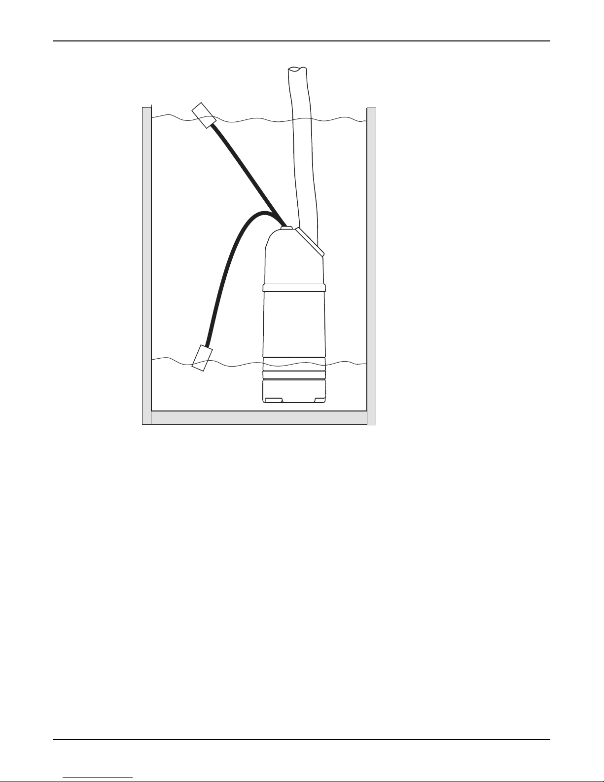
Starting and stopping the pump at different water levels can be manual or
automatic. If automatic start and stop is required, a level regulator can be
ordered (as an option). The option is only available for standard pumps.
Features
Below are some of the features of the level regulators:
• The level regulator can be set at different operating levels by adjusting the
length of cable.
• A clamping bracket situated at the lifting handle holds the level regulator
cable in place.
• If continuous pumping is required, the level regulator can be placed in a
special rubber bracket on the discharge connection to eliminate the level
regulator function.
Medium head
10 8122.210 Macro Installation, Operation, and Maintenance Manual
Page 13
Illustration
1
2
Product Description (Continued)
The data plate
Introduction
1. On
2. Off
Figure 1: The functionality of the level regulator
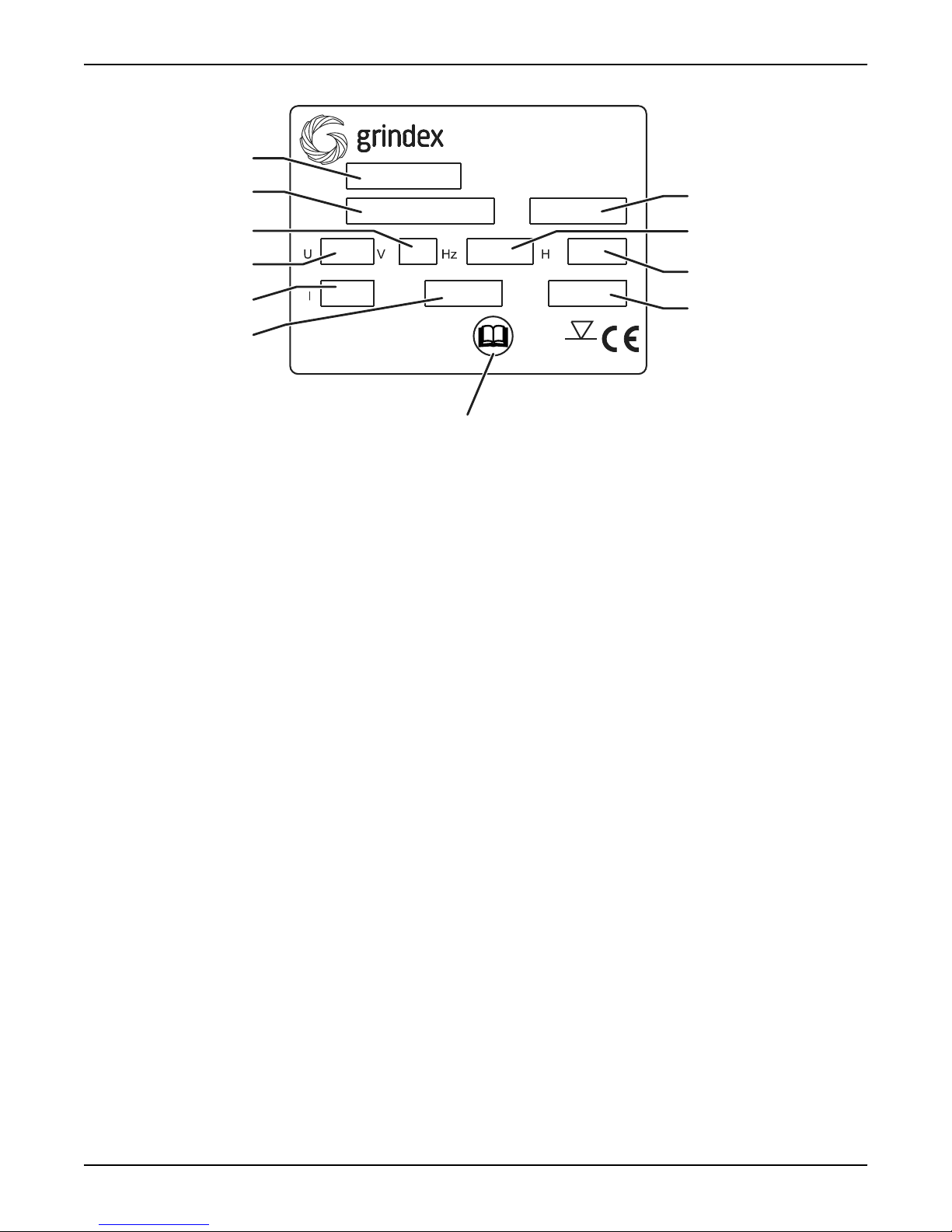
The data plate is a metal label located on the main body of the pump. The data
plate lists key product specifications.
8122.210 Macro Installation, Operation, and Maintenance Manual 11
Page 14
Made in Sweden
IEC 335-2-41 Class F
IP 68
5 m
Grindex AB Sweden
www.grindex.com
Type No.
QPA
max
max
1
2
3
4
5
6
7
8
11
10
9
Product Description (Continued)
The data plate
1. Serial number
2. Product weight
3. Maximum head
4. Maximum capacity
5. Read installation manual
6. Output power
7. Rated current
8. Rated voltage
9. Frequency
10. Product number
11. Pump model
12 8122.210 Macro Installation, Operation, and Maintenance Manual
Page 15
Installation
Install the pump
WARNING:
• Before installing the pump, check that the cable and cable entry have not
been damaged during transportation.
• Make sure that the pump cannot roll or fall over and injure people or damage
property.
NOTICE:
• Never force piping to make a connection with a pump.
These requirements apply:
• Use the pump dimensional drawing in order to ensure proper installation.
• Provide a suitable barrier around the work area, for example, a guard rail.
• Check the explosion risk before you weld or use electric hand tools.
• Remove all debris from the inlet piping system before you install the pump.
Installation
Sedimentation prevention
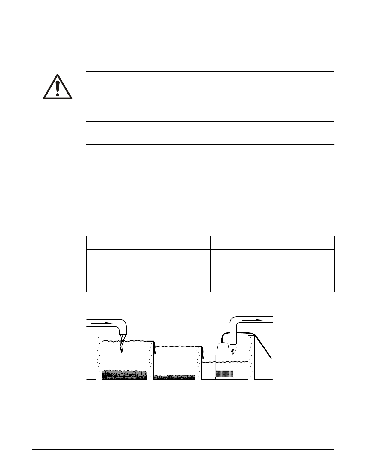
In order to avoid sedimentation when the pumped liquid contains solid particles,
the velocity of the liquid in the discharge line must exceed a certain value.
Choose applicable minimum velocity from the table, and choose proper dimension
of the discharge line accordingly.
Mixture Minimum velocity, meter per second
Water + coarse gravel 4 (13)
Water + gravel 3.5 (11)
Water + sand, particle size <0.6 mm
(0.024 in.)
Water + sand, particle size <0.1 mm
(0.004 in.)
For more permanent installations with a heavily contaminated pumped liquid, a
settling pump-sump is recommended.
(feet per second)
2.5 (8.2)
1.5 (4.9)
Figure 2: Settling pump-sump
Discharge line requirements
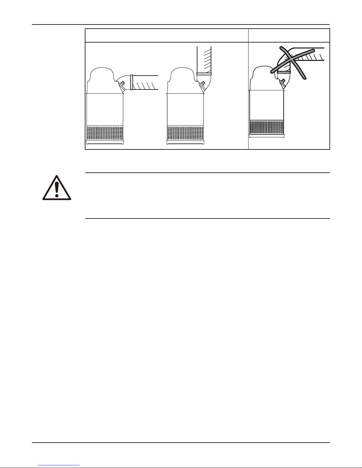
The discharge line can be run vertically or horizontally, but must be without sharp
bends.
8122.210 Macro Installation, Operation, and Maintenance Manual 13
Page 16
Installation (Continued)
Fasteners
Proper horizontal and vertical installation Improper installation
with a sharp bend
WARNING:
• Only use fasteners of the proper size and material.
• Replace all corroded fasteners.
• Make sure that all fasteners are properly tightened and that there are no
missing fasteners.
Install
The pump is transportable and intended to operate either completely or partially
submerged in the pumped liquid. The pump is equipped with a connection for
hose or pipe.
These requirements and instructions only apply when the installation is made
according to the dimensional drawing.
1. Run the cable so that it has no sharp bends, is not pinched, and cannot be
sucked into the pump inlet.
2. Connect the discharge line.
The discharge line can be run vertically or horizontally, but must be without
sharp bends.
3. Lower the pump into the sump.
The cable must not be used for this purpose. You should attach a rope or
similar to the handle or the eyebolts for lowering and lifting the pump.
Heavier pumps must be lifted and lowered down by crane. Suspend the pump
by the lifting handle or the eyebolts with chains or wires.
4. Place the pump on the base and make sure it cannot fall over or sink.
The base should consist of a plank, a bed of coarse gravel, or a cut-down and
perforated oil drum.
Alternatively, the pump can be suspended with a lifting chain just above the
sump bottom. Make sure that the pump cannot rotate at startup or during
operation.
5. Connect the motor cable and the starter and monitoring equipment according
to the separate instructions.
Make sure that the impeller rotation is correct. For more information, see
Check the impeller rotation (page 17).
14 8122.210 Macro Installation, Operation, and Maintenance Manual
Page 17
Make the electrical connections
General precautions
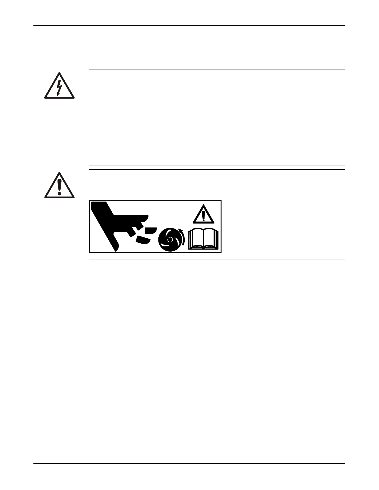
Electrical Hazard:
• A certified electrician must supervise all electrical work. Comply with all local
codes and regulations.
• Before starting work on the pump, make sure that the pump and the control
panel are isolated from the power supply and cannot be energized. This
applies to the control circuit as well.
• Leakage into the electrical parts can cause damaged equipment or a blown
fuse. Keep the end of the motor cable above the liquid level.
• Make sure that all unused conductors are insulated.
• There is a risk of electrical shock or explosion if the electrical connections are
not correctly carried out or if there is fault or damage on the product.
CAUTION:
If the pump is equipped with automatic level control and/or internal contactor,
there is a risk of sudden restart.
Installation (Continued)
Requirements
These general requirements apply for electrical installation:
• The supply authority must be notified before installing the pump if it will be
connected to the public mains. When the pump is connected to the public
power supply, it may cause flickering of incandescent lamps when started.
• The mains voltage and frequency must agree with the specifications on the
data plate. If the pump can be connected to different voltages, the connected
voltage is specified by a yellow sticker close to the cable entry.
• The fuses, short-circuit, and circuit breakers must have the proper rating, and
the pump overload protection (motor protection breaker) must be connected
and set to the rated current according to the data plate and if applicable the
cable chart. The starting current in direct-on-line starting can be up to six
times higher than the rated current.
• The fuse rating and the cables must be in accordance with the local rules and
regulations.
• If intermittent operation is prescribed, the pump must be provided with
monitoring equipment supporting such operation.
• The thermal contacts must be in use.
8122.210 Macro Installation, Operation, and Maintenance Manual 15
Page 18

Installation (Continued)
Cables
These are the requirements to follow when you install cables:
• The cables must be in good condition, not have any sharp bends, and not be
pinched.
• The sheathing must not be damaged and must not have indentations or be
embossed (with markings, etc.) at the cable entry.
• The minimum bending radius must not be below the accepted value.
• If the outer sheath of the cable is damaged, then replace the cable. Contact a
Grindex service shop.
• The voltage drop in long cables must be taken into account. The drive unit’s
rated voltage is the voltage measured at the terminal board in the upper part
of the pump.
Earthing (Grounding)
Electrical Hazard:
• You must earth (ground) all electrical equipment. This applies to the pump
equipment, the driver, and any monitoring equipment. Test the earth (ground)
lead to verify that it is connected correctly.
• If the motor cable is jerked loose by mistake, the earth (ground) conductor
should be the last conductor to come loose from its terminal. Make sure that
the earth (ground) conductor is longer than the phase conductors. This
applies to both ends of the motor cable.
• Risk of electrical shock or burn. You must connect an additional earth(ground-) fault protection device to the earthed (grounded) connectors if
persons are likely to come into physical contact with the pump or pumped
liquids.
Electrical connection
Color definition
Bl Blue
Bla Black
Br Brown
Gr/Ye Green/Yellow
Wh White
16 8122.210 Macro Installation, Operation, and Maintenance Manual
Page 19
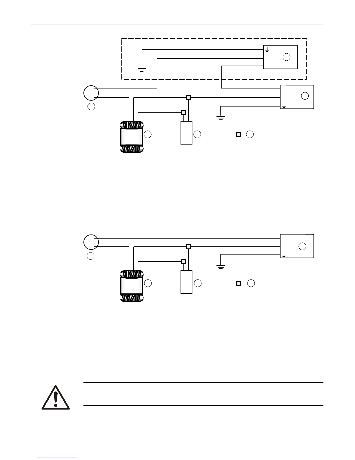
With level regulator
1
3
L
N
L
N
Bl
Bl
Wh
Wh
Wh
Br
Br
BrBrBla
Gr/Ye
Gr/Ye
=
B
A
CDE
F
1
3
L
N
Bl
BrBrBla
Gr/Ye
A
Wh Wh
=
BCD
E
A Level regulator
B Plug contact
C Connector
Installation (Continued)
D Capacitor
E Stator
F Motor protection
Without level regulator
A Plug contact
B Connector
C Capacitor
D Stator
E Motor protection
Check the impeller rotation
WARNING:
The starting jerk can be powerful.
1. Start the motor.
8122.210 Macro Installation, Operation, and Maintenance Manual 17
Page 20
Installation (Continued)
2. Stop the motor.
3. Check that the impeller rotates in the correct direction.
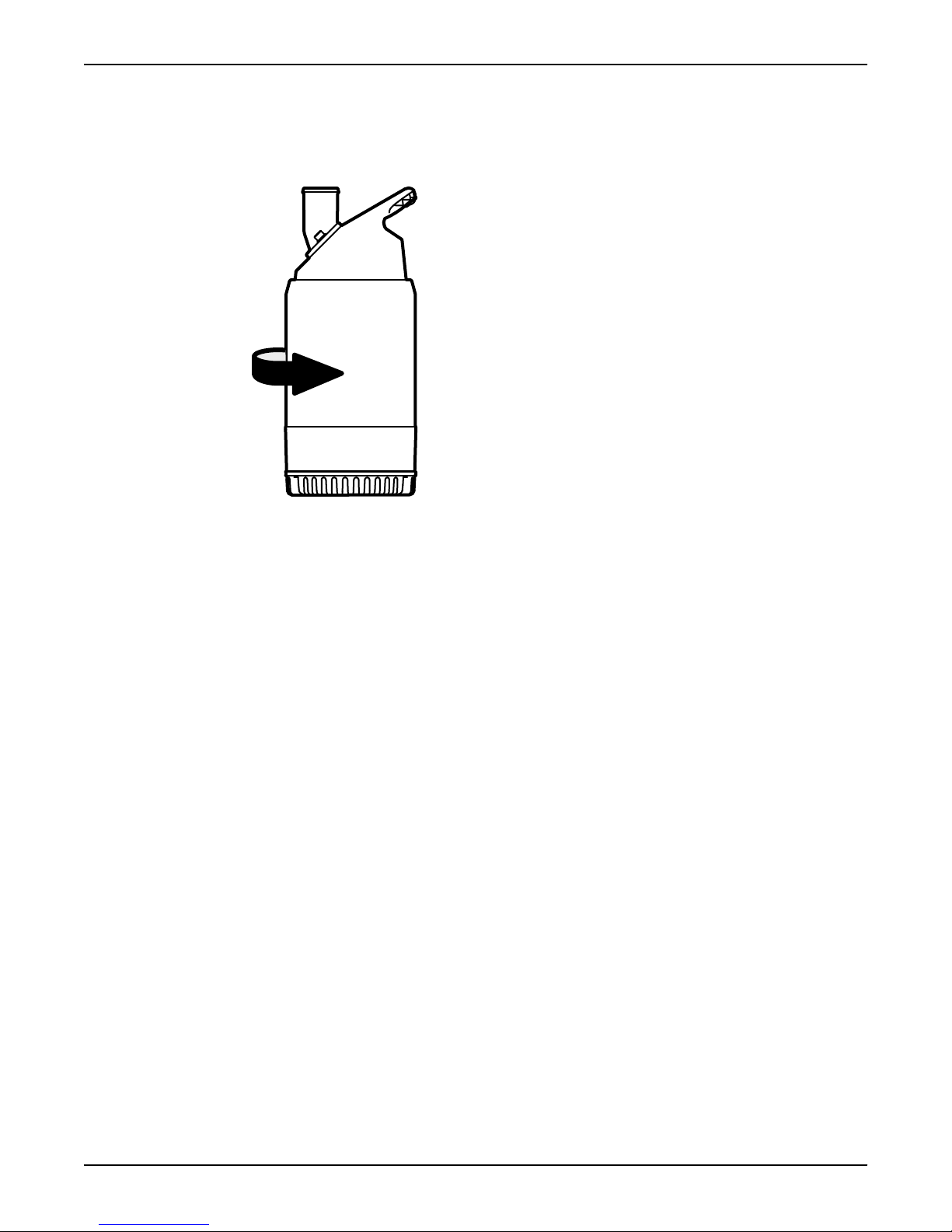
The correct direction of impeller rotation is clockwise when you look at the
pump from above. When started, the pump will react in the opposite direction
to the impeller rotation.
Figure 3: Start reaction
4. If the impeller rotates in the wrong direction, then do the following:
• If the motor has a 1-phase connection, then contact the local Grindex
shop.
18 8122.210 Macro Installation, Operation, and Maintenance Manual
Page 21
Operation
Precautions
• Never operate the pump without safety devices installed.
• Never operate the pump with the discharge valve closed.
• Make sure that all safety guards are in place and secure.
• Make sure you have a clear path of retreat.
• Never work alone.
• Beware of the risk of a sudden start if the product is used with an automatic
level control and/or internal contactor.
Distance to wet areas
Electrical Hazard:
Risk of electrical shock when pumping or mixing near a lake, jetties, beaches,
ponds, fountains, or similar. There must be a safety distance of at least 20 m
(65 ft.) between the person and the product if the person is in contact with the
pumped or mixed liquid.
Operation
Electrical Hazard:
Risk of electrical shock. This pump has not been investigated for use in swimming
pools. If used in connection with swimming pools special safety regulations apply.
Noise level
NOTICE:
The noise level of the product is lower than 70 dB. However, the noise level of
70 dB may be exceeded in some installations and at certain operating points on
the performance curve. Make sure that you understand the noise level
requirements in the environment where the pump is installed. Failure to do so
may result in hearing loss or violation of local laws.
Start the pump
WARNING:
• If you need to work on the pump, make sure that it is isolated from the power
• Make sure that the pump cannot roll or fall over and injure people or damage
• In some installations, the pump and the surrounding liquid may be hot. Bear
• Make sure nobody is close to the pump when it is started. The pump will jerk
supply and cannot be energized.
property.
in mind the risk of burn injuries.
in the opposite direction of the impeller rotation.
NOTICE:
Make sure that the rotation of the impeller is correct. For more information, see
Check the impeller rotation.
8122.210 Macro Installation, Operation, and Maintenance Manual 19
Page 22

Operation (Continued)
1. Check the oil level in the oil housing.
2. Remove the fuses or open the circuit breaker, and check that the impeller can
be rotated freely.
3. Check that the monitoring equipment (if any) works.
4. Check that the impeller rotation is correct.
5. Start the pump.
Clean the pump
The pump must be cleaned if it has been running in very dirty water. If clay,
cement or other similar dirt is left in the pump it may clog the impeller and seal,
preventing the pump from working.
Let the pump run for a while in clean water, or flush it through the discharge
connection.
20 8122.210 Macro Installation, Operation, and Maintenance Manual
Page 23
Maintenance
Precautions
WARNING:
• Always follow safety guidelines when working on the pump. See Introduction
and Safety (page 3).
• Disconnect and lock out electrical power before installing or servicing the
pump.
• Make sure that the pump cannot roll or fall over and injure people or damage
property.
• Rinse the pump thoroughly with clean water before working on the pump.
• Rinse the components in water after dismantling.
Make sure that you follow these requirements:
• Check the explosion risk before you weld or use electrical hand tools.
• Allow all system and pump components to cool before you handle them.
• Make sure that the product and its components have been thoroughly
cleaned.
• Do not open any vent or drain valves or remove any plugs while the system is
pressurized. Make sure that the pump is isolated from the system and that
pressure is relieved before you disassemble the pump, remove plugs, or
disconnect piping.
Maintenance
Maintenance guidelines
During maintenance and before reassembly, always remember to perform these
tasks:
• Clean all parts thoroughly, particularly O-ring grooves.
• Change all O-rings, gaskets, and seal washers.
• Lubricate all springs and O-rings with grease.
During reassembly, always make sure that existing index markings are in line.
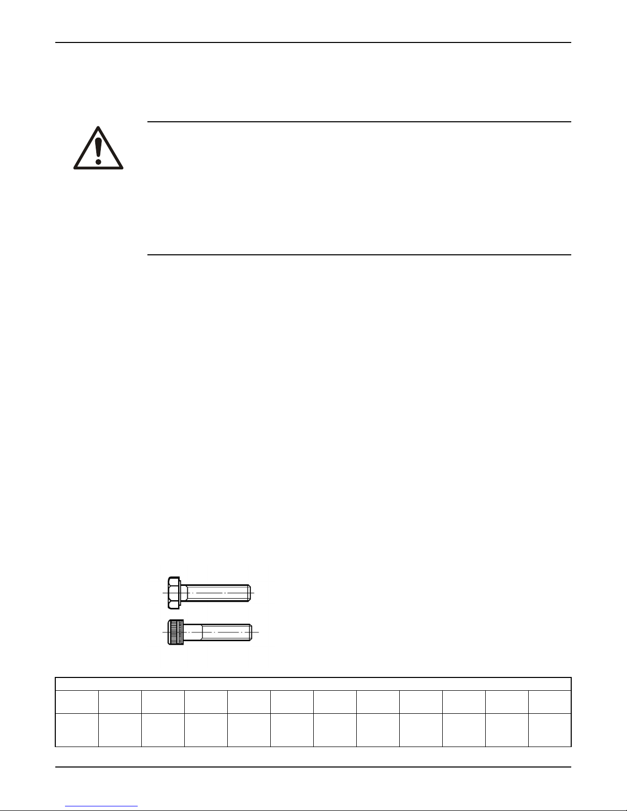
Torque values
Screw and nuts
Stainless steel, A2 and A4
Torque,
Nm (ftlbs)
Propert
y class
70
+80
M4 M5 M6 M8 M10 M12 M16 M20 M24 M30
2.7 (2) 5.4 (4) 9.3
1
(6.9)
22 (16) 44 (32) 76 (56) 187
(138)
364
(268)
629
(464)
1240
(915)
8122.210 Macro Installation, Operation, and Maintenance Manual 21
Page 24
Maintenance (Continued)
Carbon steel and alloyed steel
Torque,
Nm (ftlbs)
8.8 2.9
(2.1)
10.9
4.0
(2.9)
12.9
4.9
(3.6)
5.7
(4.2)
9.8
(7.2)
8.1 (6) 14
(10.3)33(24.3)
9.7
(7.2)17(12.5)
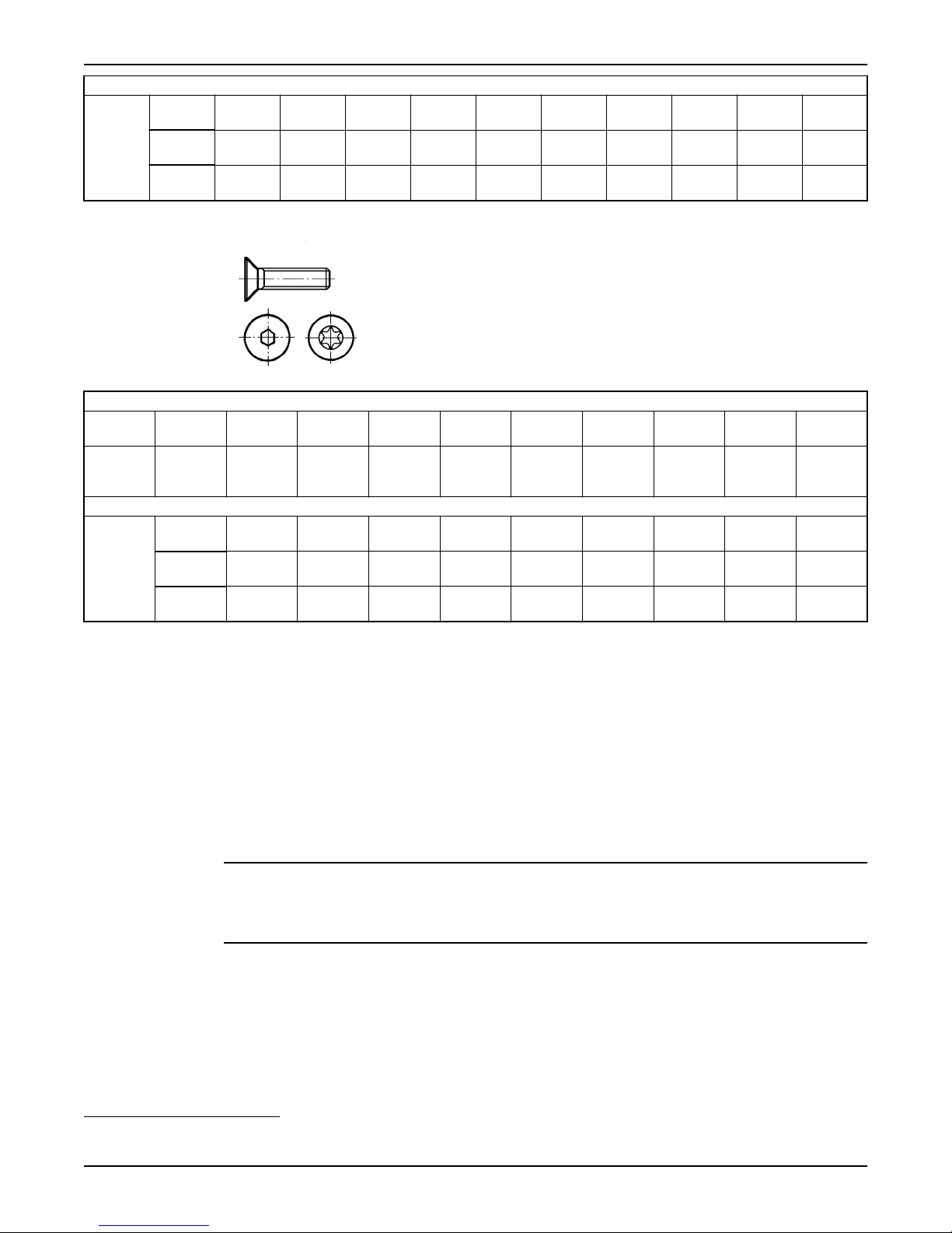
Screws with countersunk heads
Stainless steel, A2 and A4
Property
M4 M5 M6 M8 M10 M12 M16 M20 M24
class
Torque,
Nm (ft-
70 +8011.2
(0.9)
2.7 (2) 5.4 (4) 9.3
lbs)
Carbon steel and alloyed steel
Torque,
Nm (ftlbs)
8.8 2.3
(1.7)
10.9
3.2
(2.4)
12.9
3.9
(2.9)
4.6
(3.4)
6.5
(4.8)
7.8
(5.8)14(10.3)32(23.6)
24 (18) 47 (35) 81(60) 194
(143)
65 (48) 114
(84)
40 (30) 79 (58) 136
(100)
277
(204)
333
(245)
22 (16) 44 (32) 76 (56) 120
(6.9)
7.8
(5.8)
19 (14) 38 (28) 65 (48) 158
(116)
11(8) 26 (19) 52 (38) 91 (67) 222
(164)
63 (46) 109
(80)
266
(196)
385
(285)
541
(399)
649
(480)
665
(490)
935
(689)
1120
(825)
(88)
308
(228)
433
(320)
519
(383)
1310
(966)
1840
(1357)
2210
(1630)
187
(138)
532
(392)
748
(552)
896
(661)
Service
Inspection
Screw tightening
Regular service of the pump ensures more reliable operation.
The pump should be inspected at least twice a year, more frequently under
severe operating conditions.
During assembly or service of the pumps we recommend that the screws be
tightened to approximately 6–8 Nm (4.5–6 ft-lbs). The tightening torque ensures
that the parts are correctly fastened and that the pumps will operate as intended.
NOTICE:
Make sure that the oil-plug and securing screws for strainer or pump housing are
not tightened too hard.
To maintain screw tightness, use some mineral oil on all non-stainless steel
screws.
When using stainless steel screws on stainless steel parts, apply Aral Degol
GS 460 or National Chemseal Thread-Eze lubricant in order to prevent the screws
from seizing.
1
Property class 70 is torque tightened as class 80.
22 8122.210 Macro Installation, Operation, and Maintenance Manual
Page 25
Troubleshooting
Introduction
Follow these guidelines when troubleshooting the pump:
• Disconnect and lock out the power supply except when conducting checks
that require voltage.
• Make sure that no one is near the pump when the power supply is
reconnected.
• When troubleshooting electrical equipment, use the following:
• Universal instrument multimeter
• Test lamp (continuity tester)
• Wiring diagram
The pump does not start
WARNING:
Always disconnect and lock out power before servicing to prevent unexpected
startup. Failure to do so could result in death or serious injury.
Troubleshooting
NOTICE:
Do NOT override the motor protection repeatedly if it has tripped. Doing so may
result in equipment damage.
Cause Remedy
An alarm signal has been
triggered on the control
panel.
The pump does not start
automatically, but can be
started manually.
The installation is not
receiving voltage.
The impeller is stuck. Clean:
Check that:
• The impeller rotates freely.
• The sensor indicators do not indicate an alarm.
• The overload protection is not tripped.
If the problem still persists:
Contact the local Grindex service shop.
Check that:
• The start level regulator is functioning. Clean or
replace if necessary.
• All connections are intact.
• The relay and contactor coils are intact.
• The control switch (Man/Auto) makes contact in
both positions.
Check the control circuit and functions.
Check that:
• The main power switch is on.
• There is control voltage to the start equipment.
• The fuses are intact.
• There is voltage in all phases of the supply line.
• All fuses have power and that they are securely
fastened to the fuse holders.
• The overload protection is not tripped.
• The motor cable is not damaged.
8122.210 Macro Installation, Operation, and Maintenance Manual 23
Page 26
Troubleshooting (Continued)
Cause Remedy
• The impeller
• The sump in order to prevent the impeller from
clogging again.
If the problem persists, contact the local Grindex service shop. Always state the
product number and the serial number of your pump when you contact Grindex,
see Product Description (page 10).
The pump does not stop when a level sensor is used
WARNING:
Always disconnect and lock out power before servicing to prevent unexpected
startup. Failure to do so could result in death or serious injury.
Cause Remedy
The pump is unable to
empty the sump to the
stop level.
There is a malfunction in
the level-sensing
equipment.
The stop level is set too
low.
Check that:
• There are no leaks from the piping and/or discharge
connection.
• The impeller is not clogged.
• The non-return valve(s) are functioning properly.
• The pump has adequate capacity. For information:
Contact the local Grindex service shop.
• Clean the level regulators.
• Check the functioning of the level regulators.
• Check the contactor and the control circuit.
• Replace all defective items.
Raise the stop level.
If the problem persists, contact the local Grindex service shop. Always state the
product number and the serial number of your pump when you contact Grindex,
see Product Description (page 10).
The pump starts-stops-starts in rapid sequence
Cause Remedy
The pump starts due to
back-flow which fills the
sump to the start level
again.
The self-holding function
of the contactor
malfunctions.
Check that:
• The distance between the start and stop levels is
not too small.
• The non-return valve(s) work(s) properly.
• The rinser is not too long without a non-return
valve.
Check:
• The contactor connections.
• The voltage in the control circuit in relation to the
rated voltages on the coil.
• The functioning of the stop-level regulator.
• Whether the voltage drop in the line at the starting
surge causes the contactor's self-holding
malfunction.
24 8122.210 Macro Installation, Operation, and Maintenance Manual
Page 27
If the problem persists, contact the local Grindex service shop. Always state the
product number and the serial number of your pump when you contact Grindex,
see Product Description (page 10).
The pump runs but the motor protection trips
WARNING:
Always disconnect and lock out power before servicing to prevent unexpected
startup. Failure to do so could result in death or serious injury.
NOTICE:
Do NOT override the motor protection repeatedly if it has tripped. Doing so may
result in equipment damage.
Cause Remedy
The motor protection is
set too low.
The impeller is difficult to
rotate by hand.
The drive unit is not
receiving full voltage on
all three phases.
The phase currents vary,
or they are too high.
The insulation between
the phases and ground in
the stator is defective.
The density of the
pumped fluid is too high.
The ambient temperature
exceeds the maximum
ambient temperature.
There is a malfunction in
the overload protection.
Set the motor protection according to the data plate
and if applicable the cable chart.
• Clean the impeller.
• Clean out the sump.
• Check that the impeller is properly trimmed.
• Check the fuses. Replace fuses that have tripped.
• If the fuses are intact, notify a certified electrician.
Contact the local Grindex service shop.
1. Use an insulation tester. With a 1000 V DC
megger, check that the insulation between the
phases and between any phase and ground is >
5 megohms.
2. If the insulation is less:
Contact the local Grindex service shop.
Make sure that the maximum density is 1100 kg/m
(9.2 lb/US gal)
• Change to a more suitable pump.
• Contact the local Grindex service shop.
The pump must not be used for such an application.
Replace the overload protection.
Troubleshooting (Continued)
3
If the problem persists, contact the local Grindex service shop. Always state the
product number and the serial number of your pump when you contact Grindex,
see Product Description (page 10).
The pump delivers too little or no water
WARNING:
Always disconnect and lock out power before servicing to prevent unexpected
startup. Failure to do so could result in death or serious injury.
8122.210 Macro Installation, Operation, and Maintenance Manual 25
Page 28
Troubleshooting (Continued)
NOTICE:
Do NOT override the motor protection repeatedly if it has tripped. Doing so may
result in equipment damage.
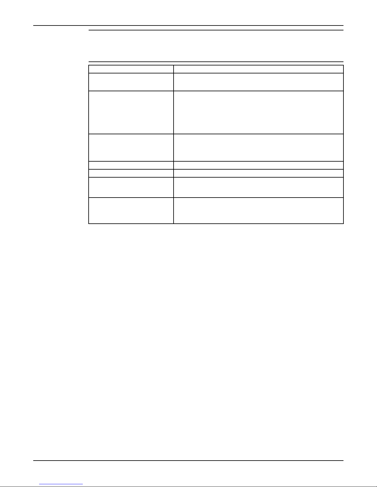
Cause Remedy
The impeller rotates in the
wrong direction.
One or more of the valves
are set in the wrong
positions.
The impeller is difficult to
rotate by hand.
The pipes are obstructed. Clean out the pipes to ensure a free flow.
The pipes and joints leak. Find the leaks and seal them.
There are signs of wear on
the impeller, pump, and
casing.
The liquid level is too low.
• If it is a 1-phase pump:
Contact the local Grindex service shop.
• Reset the valves that are set in the wrong position.
• Replace the valves, if necessary.
• Check that all valves are correctly installed
according to media flow.
• Check that all valves open correctly.
• Clean the impeller.
• Clean out the sump.
• Check that the impeller is properly trimmed.
Replace the worn parts.
• Check that the level sensor is set correctly.
• Depending on the installation type, add a means for
priming the pump, such as a foot valve.
If the problem persists, contact the local Grindex service shop. Always state the
product number and the serial number of your pump when you contact Grindex,
see Product Description (page 10).
26 8122.210 Macro Installation, Operation, and Maintenance Manual
Page 29
Technical Reference
Application limits
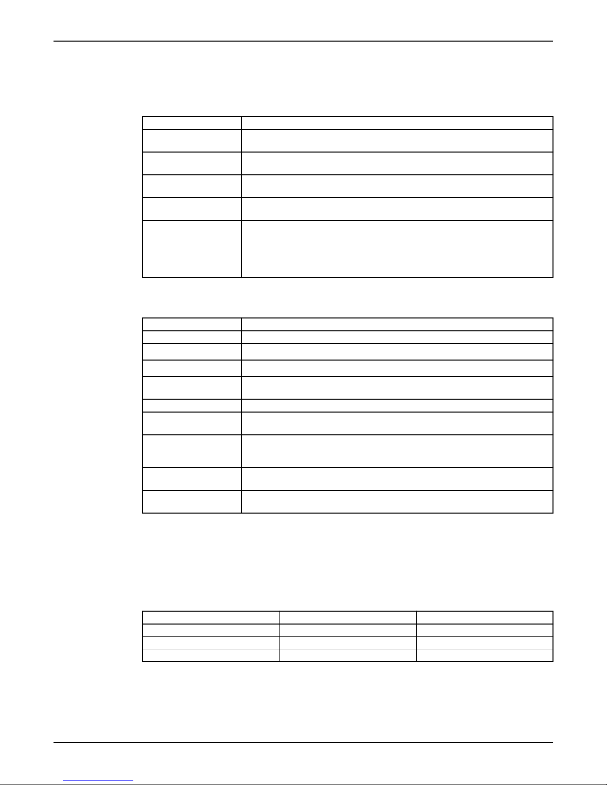
Data Description
Media (liquid)
temperature
pH of the pumped
media (liquid)
Media (liquid)
density
Depth of
immersion
Other For specific weight, current, voltage, power rating, and speed
Motor data
5–35°C (41–95°F)
3–9
Maximum density: 1100 kg/m3 (9.2 lb. per US gal.)
5 m (16.5 ft.)
of the pump, see the data plate on the pump. For starting
current, see Motor data (page 27).
For other applications, contact the nearest Grindex
representative for information.
Technical Reference
Feature Description
Motor type Squirrel-cage induction motor
Frequency
Supply
Maximum starts
per hour
Code compliance IEC 60034-1
Rated output
variation
Voltage variation
without
overheating
Voltage imbalance
tolerance
Stator insulation
class
Specific motor data
1-phase, 50 Hz
Motor type:
• 2,770 rpm
• 750 W (1.0 hp)
Voltage (V) Rated current (A) Starting current (A)
115 8.7 43
230 4.2 19
240 4 20
50 or 60 Hz
1-phase
30 evenly spaced starts per hour
±10%
±10%, provided that it does not run continuously at full load
2%
F (155°C [310°F])
1-phase, 60 Hz
Motor type:
• 3,270 rpm
• 820 W (1.1 hp)
8122.210 Macro Installation, Operation, and Maintenance Manual 27
Page 30
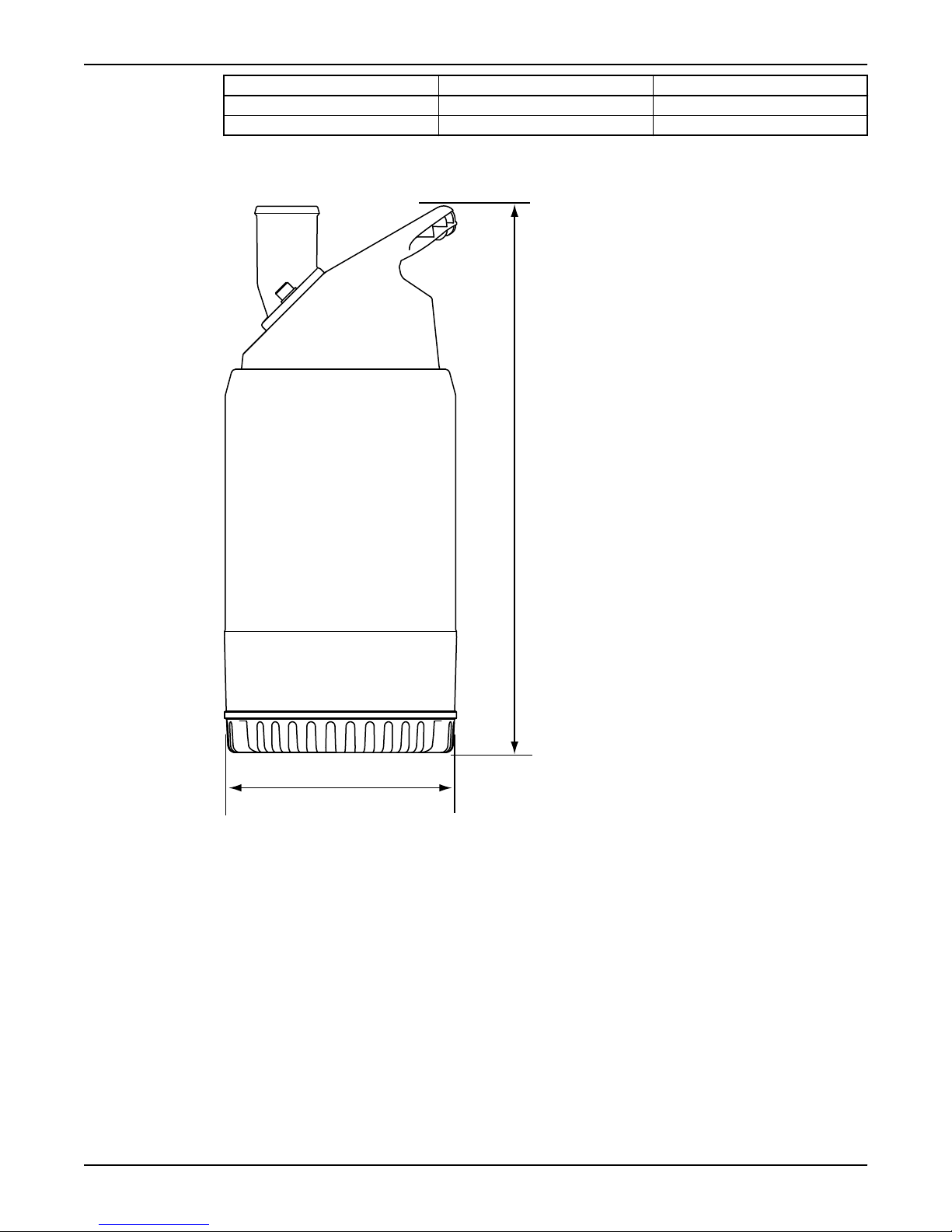
430 mm (17 in.)
Ø 185 mm (7.3 in.)
Technical Reference (Continued)
Voltage (V) Rated current (A) Starting current (A)
115 9.8 40
230 4.8 17
Dimensions and weights
Weight without motor cable: 12.5 kg (27.5 lbs)
Performance curves
Standard
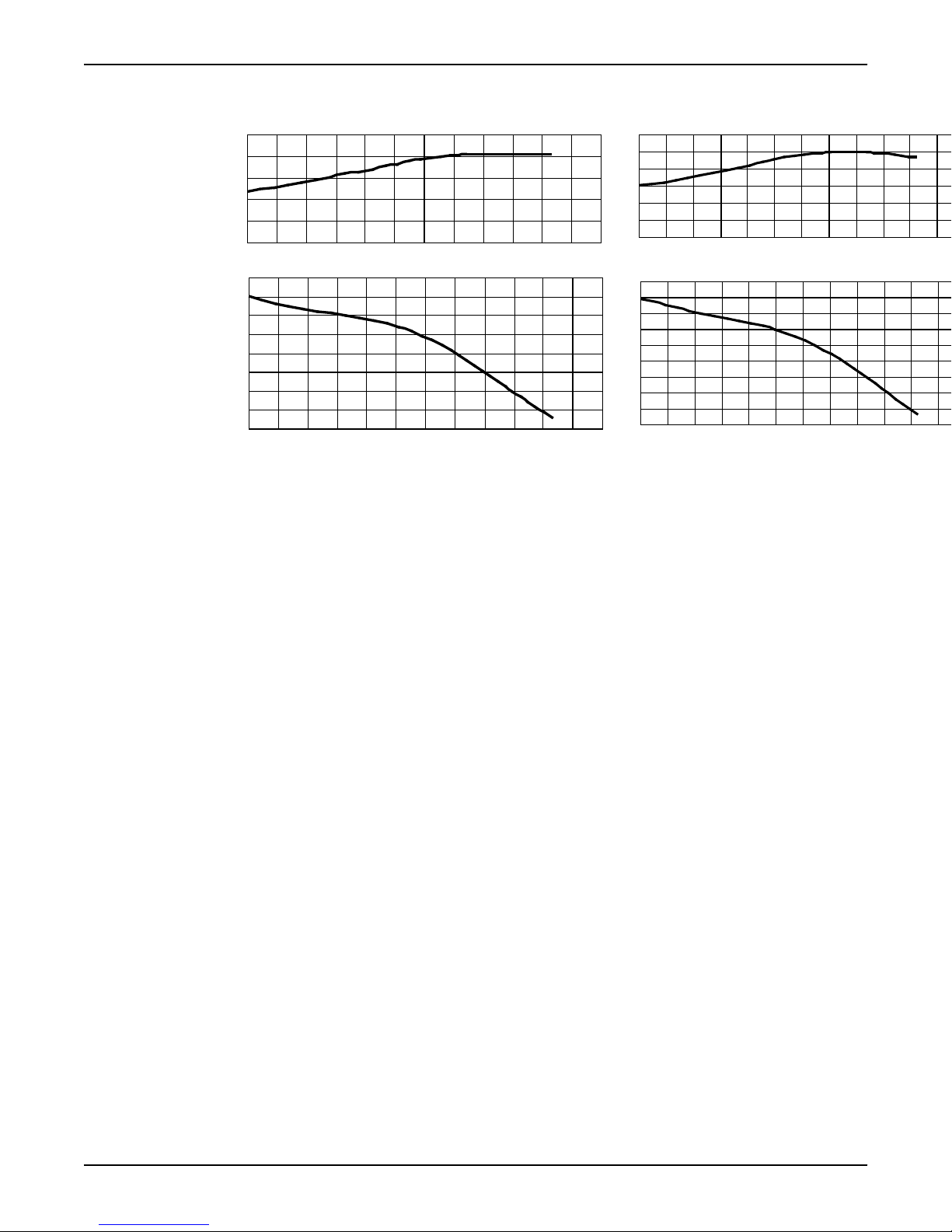
Pumps are tested in accordance with ISO 9906, HI level A.
28 8122.210 Macro Installation, Operation, and Maintenance Manual
Page 31
Macro
0
2
4
6
8
10
12
14
16
0.0 1.0 2.0 3.0 4.0 5.0 6.0
0.0
0.2
0.4
0.6
0.8
1.0
P1 [kW]
H [m]
Q [l/s]
0
2
4
6
8
10
12
14
16
18
0.0 1.0 2.0 3.0 4.0 5.0 6.0
0.0
0.2
0.4
0.6
0.8
1.0
1.2
P1 [kW]
H [m]
Q [l/s]
Technical Reference (Continued)
Figure 4: 50 Hz
8122.210 Macro Installation, Operation, and Maintenance Manual 29
Figure 5: 60 Hz
Page 32

Page 33

Page 34

www.grindex.com
©
2009 Grindex. The original instruction is in English. All non-English instructions are translations of the original instruction.
Grindex
Gesällvägen 33
174 87 Sundbyberg
Sweden
Tel. +46-8-606 66 00
Fax +46-8-745 53 28
898438_1.0_en.US_2009-12_IOM.8122.210
 Loading...