

Page 1
Cycle Analyst V3.1
Official User Manual
Grin Technologies Ltd
Vancouver, BC, Canada
ph: (604) 569-0902
email: info@ebikes.ca
web: http://www.ebikes.ca
Copyright © 2019
Page 2

Cycle Analyst V3.1 User Manual
Rev 1.0
Table of Contents
1 Introduction...................................................................................3
2 High Level Operation....................................................................3
3 Installation....................................................................................4
3.1 Handlebar Wiring.....................................................................................4
3.2 Shunt / Controller Wiring.........................................................................6
4 Display Screens.............................................................................7
4.1 Main Display..............................................................................................7
4.2 Diagnostics Screen, Display #12...............................................................8
4.3 Wh/km, Display #4....................................................................................9
5 Resetting the Trip Counter............................................................9
6 Setup Menu..................................................................................10
6.1 Accessing and Navigating the Setup Menu ...........................................10
6.2 Setting the Speedometer..........................................................................11
6.3 Setting Up the Battery.............................................................................14
6.4 Throttle Input Settings............................................................................17
6.5 Output Throttle Settings.........................................................................19
6.6 Setup Speed Limits..................................................................................19
6.7 Setup Power Limits.................................................................................20
6.8 Setting Up PAS or Torque Sensors........................................................21
6.9 PAS Configuration..................................................................................22
6.10 Temperature Sensor..............................................................................24
6.11 Setup Auxiliary Control Inputs............................................................25
6.12 Setup Ebrakes and Regen. ...................................................................27
6.13 Set Current Sense Shunt Resistance....................................................28
6.14 Using Presets..........................................................................................30
6.15 Display Customization..........................................................................31
7 Data Logging...............................................................................31
8 Software Setup Utility .................................................................33
9 Common Mistakes.......................................................................34
10 Enjoy your Ride and Remember to Reset..................................35
11 Specifications.............................................................................36
2
Page 3
Cycle Analyst V3.1 User Manual
Rev 1.0
1 Introduction
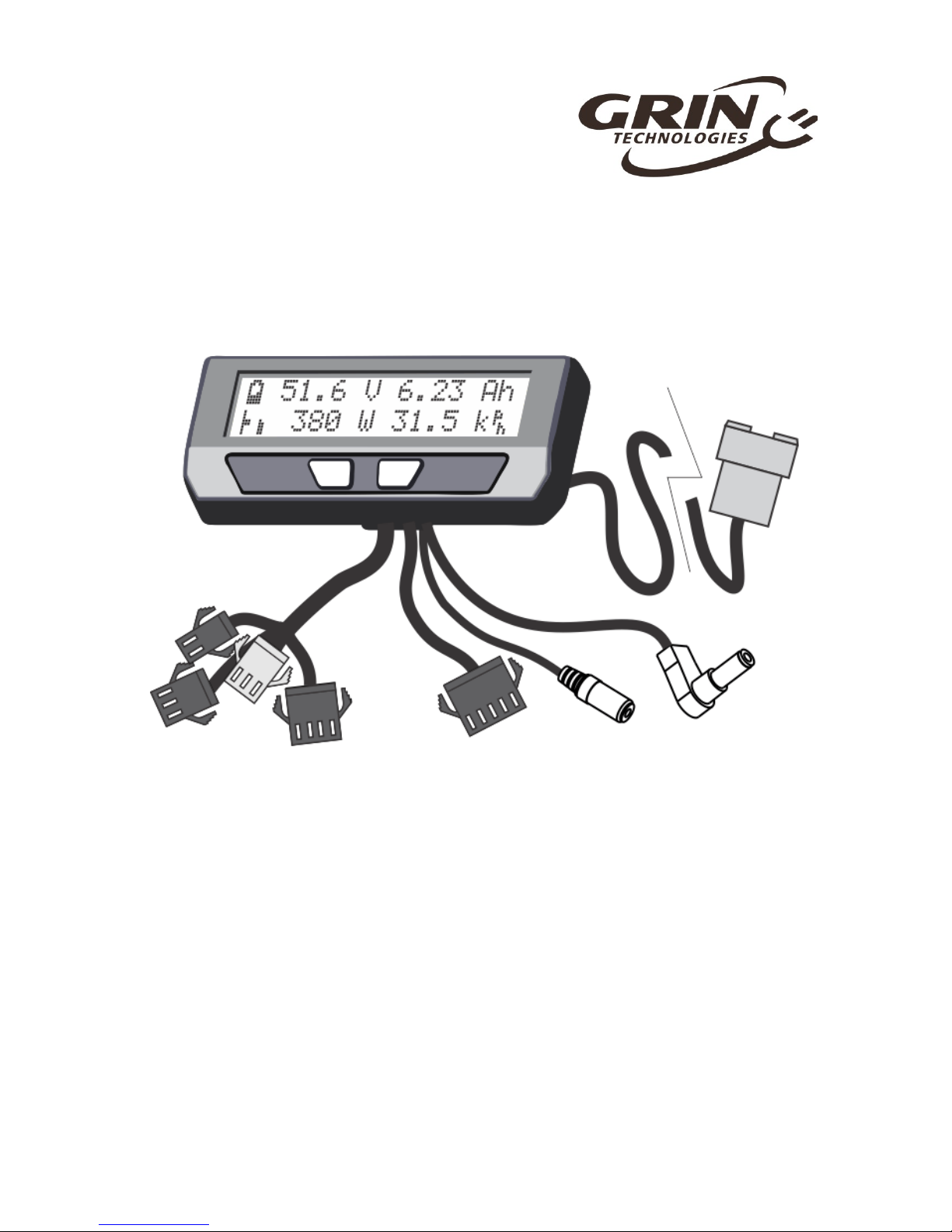
Thank you for the purchase of a V3 Cycle Analyst device, Grin's latest model of
open standard display and control device for ebikes and other electric vehicles.
This document should help you get reasonably familiar with the basic setup and
operation of a CA3 as part of your vehicle system.
2 High Level Operation
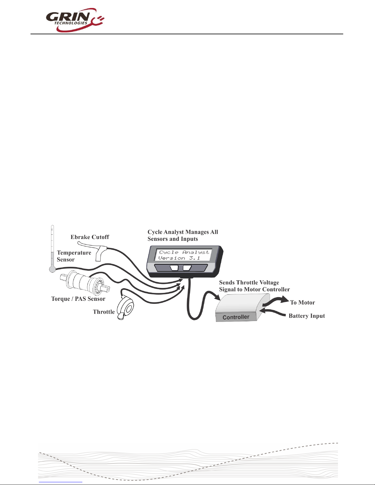
The V3 Cycle Analyst is not like a typical ebike display interface that
communicates with one particular model of motor controller. Instead the CA3 is
designed as a more universal display and control unit. To achieve this
universality, it reads existing signals already present in most EV drives to sense
the power and speed of the vehicle, and then it regulates the motor power
through a common throttle signal.
This is an important concept to understand; the CA3 does not "communicate"
with your ebike in the same manner as proprietary display units. Rather it taps
into analog signals already present inside a motor controller and interprets them.
It then sends what it thinks is the most appropriate throttle voltage to your
controller for generating a target amount of power from the motor.
As far as your motor controller knows, the V3 Cycle Analyst is just a throttle
device. The CA3 can't change any internal controller settings, or make the
controller do anything more than what you could do via deft manipulation of a
normal throttle.
3
Page 4
Cycle Analyst V3.1 User Manual
Rev 1.0
3 Installation
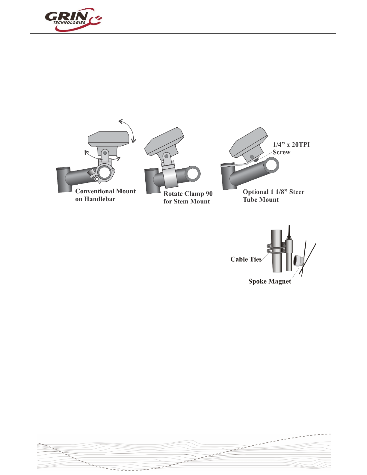
The Cycle Analyst includes a handlebar bracket that allows it to clamp on any
tube from 21mm (7/8”) to 40mm (1.5”) in diameter. You can mount it directly on
the handlebar, or you can swivel the base 90 degrees and clamp it to the stem
for a more central display that doesn’t consume bar real estate. There is also an
optional steer tube mounting bracket and a ¼” threaded insert on the bottom of
the enclosure for improvised attachments.
If you have a CA3-DPS device which uses an
external spoke magnet and separate speedometer
sensor, then you will need to screw the spoke
magnet to your wheel and zip-tie the sensor pickup
to your fork so that the magnet passes within about
5mm from the middle of the pickup sensor. To avoid
glitches in the speed reading, the sensor body
should be perpendicular to the direction of magnet
motion.
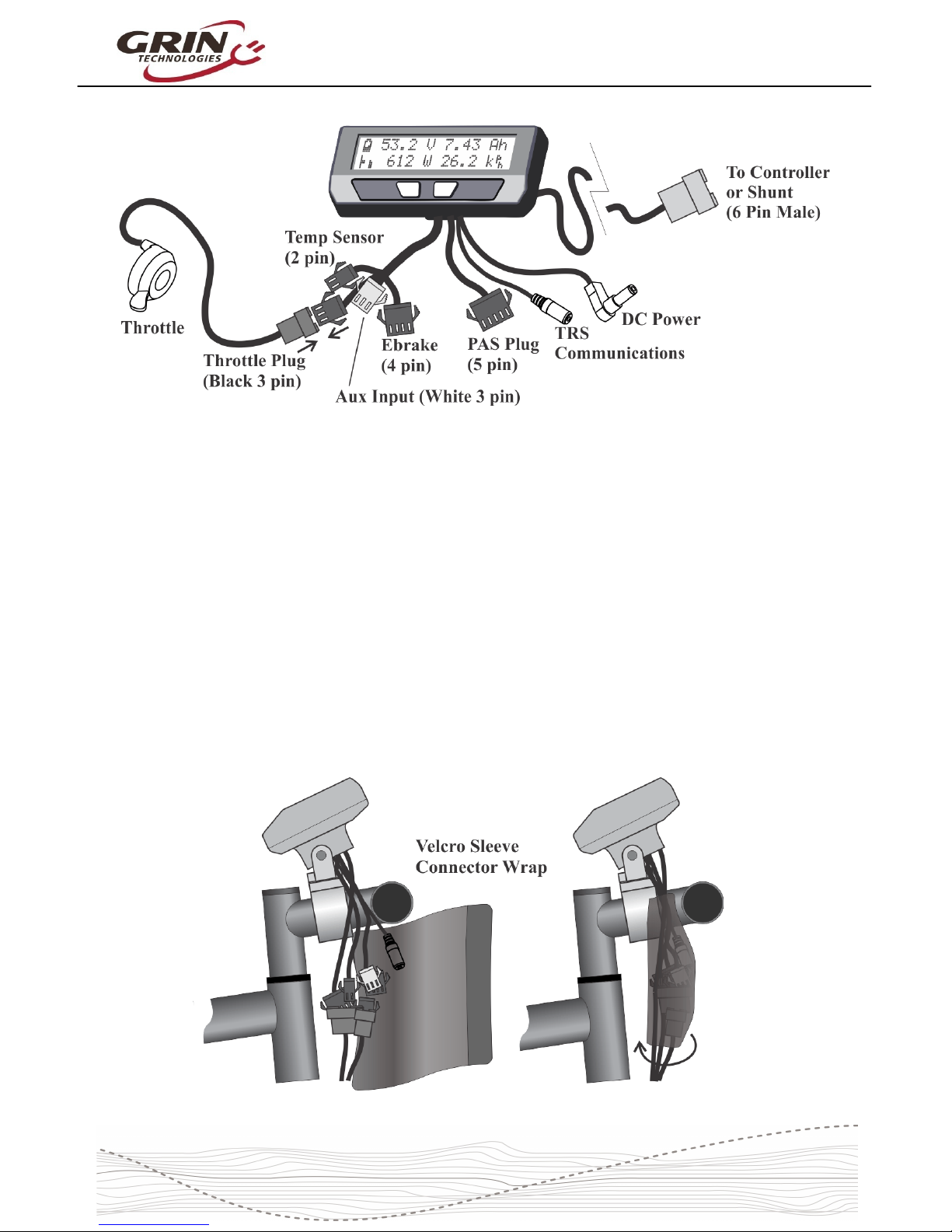
3.1 Handlebar Wiring
It is important that you wire up your throttle to plug into the Cycle Analyst rather
than directly to your motor controller. The CA3 has a short cable bundle for all
accessories and the throttle input is the black 3-pin connector. Your throttle
should be attached to this plug.
You can also connect ebrake cutoffs, auxiliary inputs, a temperature sensor, and
Pedal Assist (PAS) or torque sensors if you have them to the appropriate
connectors on CA3, but the throttle is the most essential for basic operation.
4
Page 5
Cycle Analyst V3.1 User Manual
Rev 1.0
There are two additional short cables coming out of the Cycle Analyst. One is an
1/8” TRS communications jack that can be used for data logging or connecting to
a computer for firmware updates and setting changes. The other is a DC Power
cable that has full battery voltage for powering front ebike lights, DC-DC
converters, and other peripherals that can run directly off pack voltage.
This DC power tap is fused internally and is limited to 1 amp. It is shipped with a
rubber protective cap and you should leave this cap in place if you are not using
the connector, as there is full battery voltage present on the exposed connector
pin.
We include a stretchy fabric Velcro sleeve that lets you cover up the connector
assembly for a clean finished look on the front of your bike once everything has
been plugged in. This sleeve also provides a convenient place for bundling up
any excess cable length.
5
Page 6
Cycle Analyst V3.1 User Manual
Rev 1.0
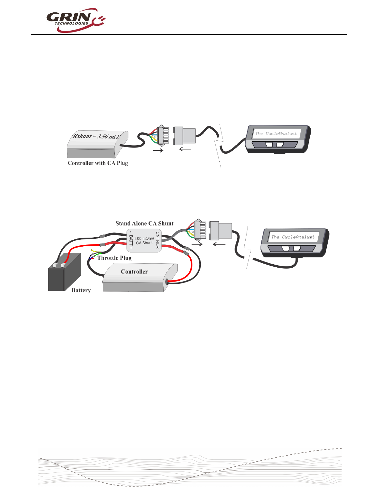
3.2 Shunt / Controller Wiring
For systems that have a CA3 compatible motor controller, the electrical hookup is
simply a matter of connecting the 6-pin CA plug to the mating plug on the
controller. This JST-SM connector standard has pins for the battery voltage,
throttle signal, speedometer signal, and current sense resistor leads.
If your controller doesn't have a compatible CA plug on it, then you will need to
use the Stand Alone Shunt wired inline with the + and – battery leads in order for
the CA to see the battery current and voltage.
The Stand Alone CA3 Shunt has a short unterminated cable with 3 signal wires
in it. The green signal wire is the throttle output of the Cycle Analyst, and that
should be wired to the throttle input plug of your motor controller. Without this
connection, the CA3 can monitor and display speed and battery consumption but
has no way to regulate and control the motor power.
The CA3 turns on whenever there is voltage on the CA plug. With direct plug
connections, if the controller has an on/off switch this would also turn the CA on
and off. If the controller does not have an on/off switch or the Stand Alone CA
shunt is used, then the the battery itself should have an on/off switch for turning
the CA on and off.
Please refer to section 6.13 about setting the Cycle Analyst Rshunt value,
especially if you are connecting the CA3 directly to a motor controller.
6
Page 7
Cycle Analyst V3.1 User Manual
Rev 1.0
4 Display Screens
When the device is powered up you can scroll through numerous display screens
by pressing the left and right buttons to show you things of interest:
Table 1: Summary of CA3.1 Display Screens
Display #1, Main Screen Summary of battery level, speed, power, voltage, distance etc.
Display #2, Electrical Only View of just the battery voltage, current, power, and amp-hours
Display #3, Human Power Shows pedal cadence and human power if torque sensor installed
Display #4, Wh/km Battery watt-hours and energy consumed per km or mile
Display #5, Human Stats Average human power, pedal cadence, and total human energy output
Display #6, % Regen Shows regenerative amp-hours and % by which it has extended your range
Display #7, Peak Stats Shows peak current, peak regen current, and battery voltage sag
Display #8, Speed Stats Maximum and average trip speed and total trip time
Display #9, Temp Stats Shows current, average, and maximum temperatures if sensor is attached
Display #10, Odometer Shows both current trip distance and lifetime odometer
Display #11, Batt Info Charge cycle count, total kWh energy used, and Battery internal resistance
Display #12, Diagnostics Live readout of throttle input/output voltages and active limiting flags
Most of the essential information you would want while riding is on Display #1.
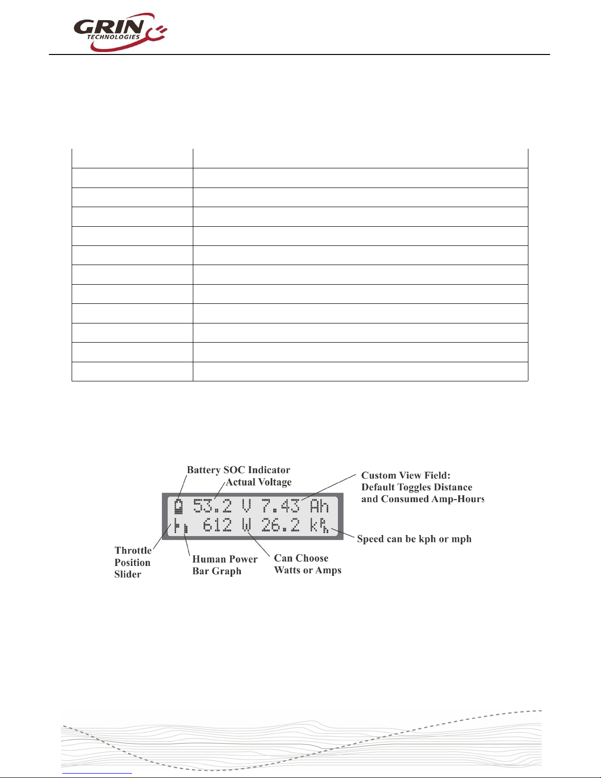
4.1 Main Display
The battery State Of Charge (SOC) icon on the top left is a graphical indication of
the charge level in your battery pack, inferred from a combination of the cell
chemistry, pack voltage, and amp-hour consumption. This gauge will only be
accurate if the battery type and series cell count has been set up correctly.
Next to that is the actual pack voltage. We recommend paying attention to your
battery voltage and becoming familiar with the value that it shows on a full
7
Page 8
Cycle Analyst V3.1 User Manual
Rev 1.0
charge, during use, and when the battery goes flat. This is often your first clue to
anomalous behavior and provides very useful troubleshooting information.
The top right is a customizable display field. By default, this toggles between
showing your accumulated amp-hours and distance since the last trip reset, but it
can be configured to show other things like motor temperature, instantaneous
wh/km, pedal cadence and so forth. You will eventually find the consumed amphours to be among the most useful and important pieces of information on the
CA display, but only if you remember to do a trip reset each time there is a fresh
charge on the battery pack.
The bottom left of the display has a throttle position that moves up and down with
the user's throttle signal going into the Cycle Analyst. This is replaced by an
animated brake lever if the ebrake cutoffs are engaged. Just beside this slider is
an animated Pedal Assist bar graph, which is only active if you have a PAS
sensor and visually indicates how fast or hard you are pedaling.
The bottom left numeric display by default shows the electrical power currently
flowing through the system, and will go negative during regenerative braking. It
is possible to change this to display amps instead of watts if you prefer.
Finally, on the bottom right is a readout of your current vehicle speed, in either
kph or mph as chosen in the setup menu.
The left and right buttons will scroll through other display screens that show
specific information that may be of interest. These screens are explained in detail
on the CA3 web page and any of them can be hidden from view if desired. The
diagnostics screen and watt-hour screen are of particular interest though.
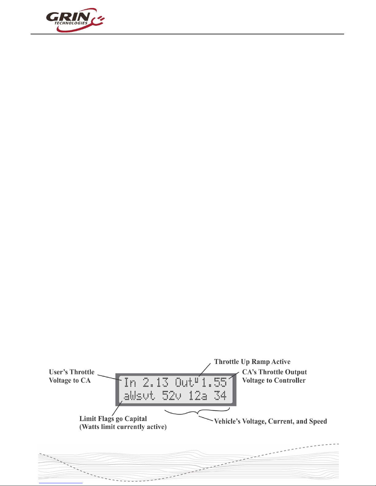
4.2 Diagnostics Screen, Display #12
If you press the left button once from the main display, you will have the
diagnostics display. This can be invaluable during any kind of system
troubleshooting. The top line shows the actual throttle voltage signal going into
the CA3, as well as the throttle voltage going out to your motor controller. If the
rate of change of the throttle is being clamped, then the associated rate limit will
show up (F = fast, U = up, P = PAS, D = down, see section 6.5).
8
Page 9
Cycle Analyst V3.1 User Manual
Rev 1.0
The bottom left shows if any of the limit settings are actively regulating the
throttle output voltage. Letters awvst refer to the Amps, Watts, low Voltage,
Speed, and Temperature rollbacks, and they become capitalized when active.
This display lets you easily identify if your input throttle is working correctly, if the
CA itself is sending an output throttle to the motor controller, and if that output
throttle is being clamped by any of the programmed limit settings.
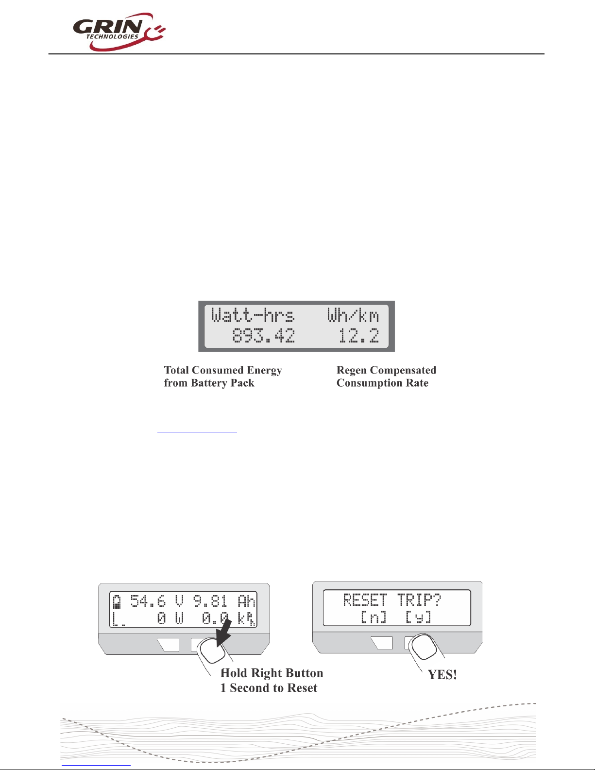
4.3 Wh/km, Display #4
The 4th display screen shows the total energy in watt-hours taken from the
battery, as well as the average watt-hours used per distance traveled, either
wh/km or wh/mi. This is one of the most useful statistics to check as it is the
equivalent of fuel mileage for your electric vehicle. You can see how different
riding styles and terrains affect your energy usage, and you can compute how
large of a battery will be required to travel a given distance.
The other 9 displays are largely self explanatory and are more thoroughly
covered on the CA3 info page.
5 Resetting the Trip Counter
If there is only one thing to remember about using the Cycle Analyst, it is that you
will want to make a habit of resetting the Cycle Analyst every time you have a
fresh charge in the battery. Do this by pressing and holding the right button until
the message "RESET TRIP?" shows on the screen. This allows you to see your
consumed battery amp-hours on each trip and ensures that the battery cycle
statistics are accurate.
9
Page 10
Cycle Analyst V3.1 User Manual
Rev 1.0
If you forget to reset, the trip amp-hour, watt-hour, and distance accumulators will
eventually peg at their maximum values and you'll stop accumulating new
statistics. You also won't get the benefit of seeing an accurate battery charge
cycle count, seeing trip to trip variation in your wh/km consumption stats, and
learning exactly how many amp-hours the battery is able to deliver.
If you press the reset button on certain other display screens, it will reset just the
statistics associated with that screen, like a reset of just the peak statistics or just
the temperature data.
6 Setup Menu
If you received your CA3 as part of a complete ebike kit package then it should
be pre-configured with reasonable values for that setup and be ready to ride.
There should be little need to change anything. If it was received as an
independent device and not as part of a kit package, then there is a good chance
that you will need to change a number of settings in the CA3’s setup menu for it
to function with accurate readings. Most essential would be the wheel size,
battery details, and Rshunt value.
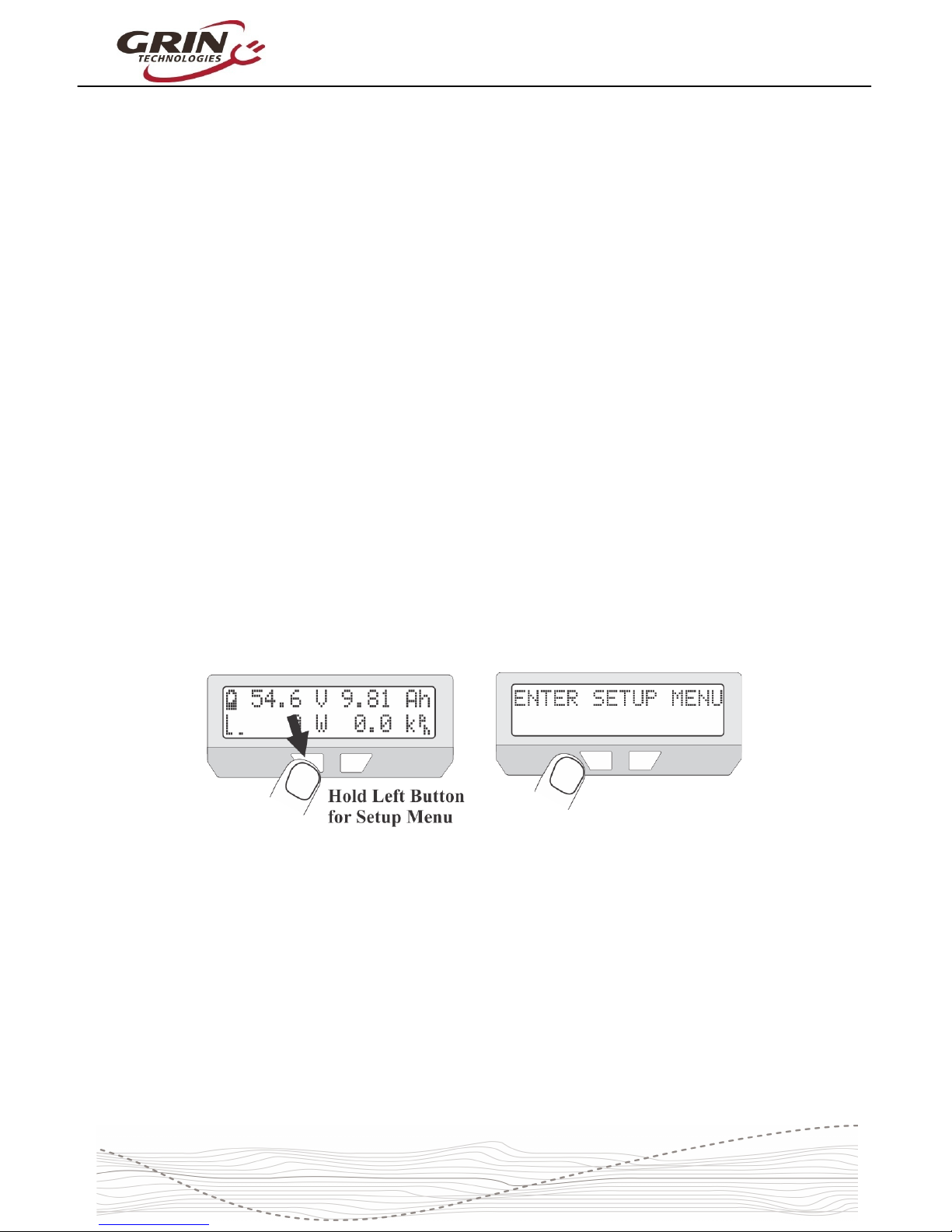
6.1 Accessing and Navigating the Setup Menu
The Setup Menu is accessed by pressing and holding the left button.
Once you are in the setup menu, the left and right buttons allow you to scroll
through the options or toggle digits up and down. Pressing and holding the
buttons has a special effect.
Hold the RIGHT button to enter a menu or save a setting (like pressing
enter on a keyboard).
Hold the LEFT button to exit something (like pressing escape on a
keyboard).
The setup page is organized with all the related settings grouped into submenus. Each of these high level menus is summarized in the table below.
10
Page 11
Cycle Analyst V3.1 User Manual
Rev 1.0
Table 2: CA3.1 Setup Menu Organization
Setup Speedometer Configure Speedometer Sensor (wheel diameter, #poles, metric/imperial)
Setup Battery Configure Battery Details (chemistry, #cells, low voltage rollback etc)
Setup Throttle Input Configure Input Throttle Mapping (min/max range, throttle mode, autocruise)
Setup Throttle Output Configure CA's Output Throttle (min/max range, ramp limits, voltage/RC Pulse)
Setup Speed Limits Set various Speed Limits and associated PID feedback parameters
Setup Power Limits Set maximum power and current limits, and feedback gain parameters
Setup PAS Device Set PAS or Torque Sensor parameters (#poles, fwd/rev direction, torque signal)
Setup PAS Configuration Configure how the CA responds to pedal RPM and torque input from rider
Setup Temperature Sensor Configure motor Temperature Sensor type and max temperature limits
Setup Analog Aux Control Setup behavior of potentiometer or 2/3 position switch for Limit Control
Setup Digital Aux Control Setup behavior of 2-button up/down Digital Limit Control
Setup Ebrake Configuration of Brake Cutoff behavior and proportional regen
Setup Calibration Calibration parameters for voltage scaling, zero offset, and Rshunt
Setup Presets Enable up to three Mode Presets for quick access to pre-configured limits
Setup Display Options Customize Display behavior, hide screens, choose custom views
Setup Miscellaneous Other parameters like data log rate, display averaging, default saving
Setup Lifetime Statistics Total Lifetime charge cycles, kilowatt hours, and odometer distance
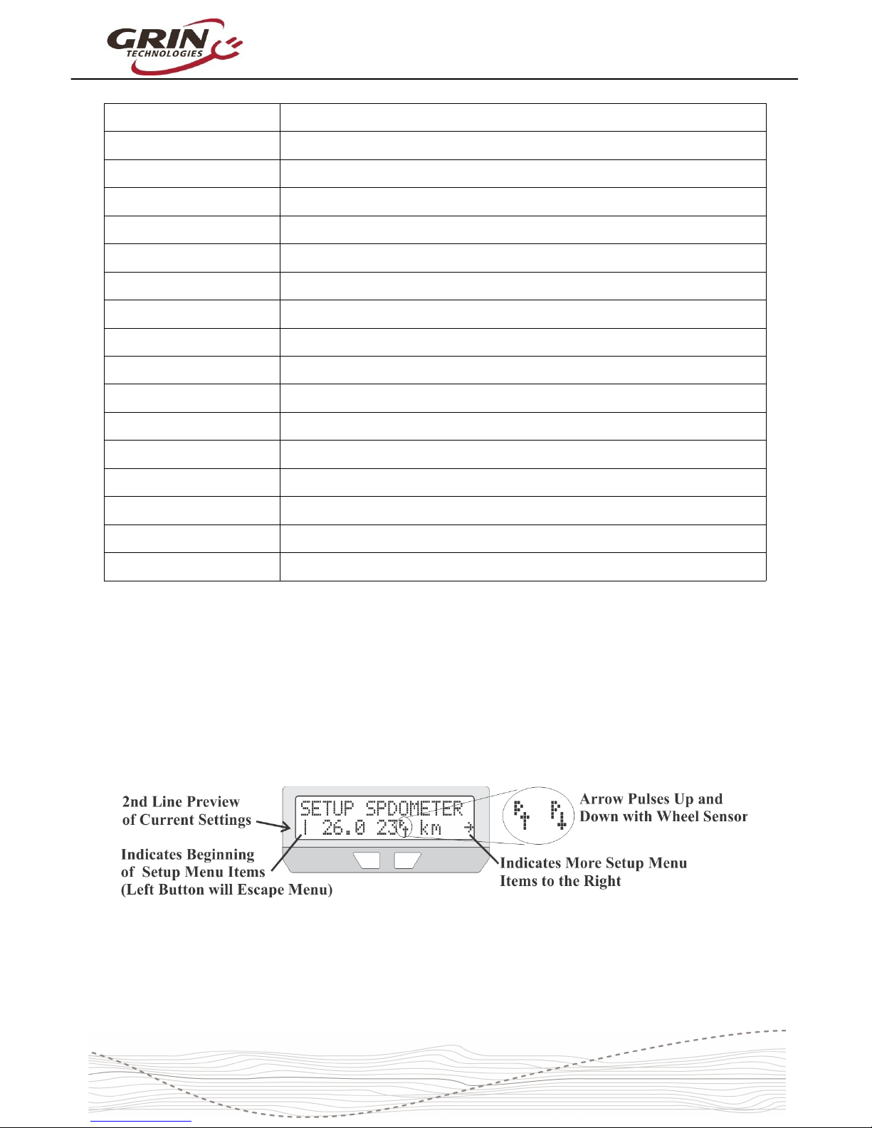
6.2 Setting the Speedometer
The first item in the setup menu is your speedometer configuration. The second
line of the setup menu shows a preview of the configured settings, including the
number of pulses per wheel revolution, the programmed wheel diameter, and
your preference of metric or imperial display.
What you may not notice on this preview line is the small wheel sensor arrow
beside the number of poles, which shows the signal going into the CA’s
speedometer input. With a spoke magnet and sensor this arrow should switch
down whenever the magnet is right by the sensor. If you have a CA3-DP device
11
Page 12

Cycle Analyst V3.1 User Manual
Rev 1.0
using the hall sensors for wheel speed, then it will toggle up and down many
times as you turn the wheel. Most setup menus provide a preview of the related
signals seen by the CA which can be valuable for setup and troubleshooting.
To change any of these settings, press and hold the RIGHT button to enter into
the speedometer setup menu.
6.2.1 Metric / Imperial Units
The first item you may want to change in the speedometer setup menu is your
preference for metric or imperial units. This is edited by pressing and holding the
button, toggling to your preferred units, and holding the button again to save.
One small detail: if you do change between miles and km in the future, your total
odometer distance will not automatically update. If there are 1000 miles present
and the units are then switched to km, it will show 1000km rather than 1598km.
6.2.2 Wheel Circumference
Accurate speed readings require an accurate wheel size. The default value of
2075mm corresponds to a diameter of exactly 26.0”, but a nominal 26” wheel is
rarely going to be exactly 26” diameter. The table below shows the approximate
value for a number of common wheel sizes, but for best accuracy you should
simply measure your wheel circumference directly with a tape ruler, or compare
the CA’s trip distance with google maps distance and adjust accordingly:
12
Page 13

Cycle Analyst V3.1 User Manual
Rev 1.0
Table 3: Approximate Tire Circumferences
Tire Size Circumf Tire Size Circumf Tire Size Circumf
16 x 1.50
1185
24 x 2.12
1965
26 x 2.25
2115
16 x 1 3/8
1282
26 x 1 1/8
1970
26 x 2.35
2131
20 x 1.75
1515
26 x 1 3/8
2068 700 x 23 2097
20 x 1 3/8
1615
26 x 1 1/2
2100 700 x 28 2136
24 x 1 1/4
1905 26 x 1.5 1995 700 x 32 2155
24 x 1.75
1890
26 x 1.75
2035 700 x 38 2180
24 x 2.00
1925 26 x 2.0 2075 29 x 2.0 2273
To edit the circumference, press and hold the right button until you see OK. The
digit you are editing will be flashing, and short presses of the left and right
buttons will cause the value to increase or decrease.
When the digit is set how you like it, then press and hold the right button to save
this and move over to the next digit. If you accidentally saved the wrong number,
you can press and hold the left button to go back to the previous digit.
Once the last digit is entered, the new value will be saved and you will be back to
navigating the speedometer setup menu.
6.2.3 Set Your Pole Count
The Cycle Analyst also needs to know how many
times the speed signal will toggle up and down with
each wheel rotation. With a CA3-DP device using a
direct drive motor this will be the number of magnetic pole pairs in the hub.
For geared hub motors that have an internal speed sensor, the #poles should be
set to the number of speed pulses on each turn of the wheel. Bafang and many
other geared motor manufacturers seem to have standardized on 6 pulse internal
speed sensors. If in doubt, simply count the number of times the 'P' arrow toggles
when the wheel is turned one revolution.
13
Page 14

Cycle Analyst V3.1 User Manual
Rev 1.0
Table 4: #Pole Settings for Common Motor System
CA3-DP with Spoke Magnet 1 Pole
Bafang Motor, Internal Speedo
6 Poles
Crystalyte 400 Series 8 Poles
Crystalyte 5000 Series 12 Poles
TDCM 5 Spd IGH Hub 16 Poles
Crystalyte NSM, SAW 20 Poles
Crystalyte ‘H’, Crown, Nine
Continent, MXUS, QS, and
most other 205mm DD motors
23 Poles
9C 212mm DD motors 26 Poles
Golden Magic Pie 28 Poles
For CA3-DPS devices using an external spoke magnet and sensor, it would be
set to the number of magnets on your wheel (typically 1, but there are some
benefits to having multiple spoke magnets)
6.3 Setting Up the Battery
The next setup menu item is the battery configuration, which is used by the Cycle
Analyst to generate an accurate State-Of-Charge (SOC) indicator. The setting
information is summarized in the Battery setup menu.
The three most important parameters to enter for an accurate SOC indicator are
the cell chemistry, series cell count, and approximate capacity. Additional options
let you choose if you want to display average cell voltage rather than pack
voltage on the main screen, whether to activate a low voltage rollback feature,
and whether to activate two preconfigured batteries (A&B) rather than just one.
See the Presets section 6.14 for more information on this.
6.3.1 Set Your Chemistry
There are 6 options for the battery chemistry:
14
Page 15

Cycle Analyst V3.1 User Manual
Rev 1.0
Li-Ion: This is a catch-all lithium ion representative of most 18650 type
lithium cells. The majority of ebike lithium packs are best represented by
this option
LiPo: This represents standard discharge rate ebike grade lithium polymer
cells, which show a fairly steady drop in voltage as the battery is drained
from 4.2V to 3.0 V/cell.
RCLiP: This is for high discharge rate polymer batteries typically used in
radio controlled models. They have a much lower drop in voltage over the
course of their discharge than regular ebike grade LiPo.
LiFe: This is for Lithium Iron Phosphate batteries, be they pouch cells (like
PING), or cylindrical cells (Like Headway, A123 etc). Iron phosphate cells
have a very flat discharge curve, but at a lower voltage than other types of
lithium (3.3V versus 3.7V nominal)
SLA: This is for lead acid batteries, whether sealed or AGM etc.
NiMH: This is for Nickel Metal Hydride or NiCad packs.
The majority of commercial lithium ebike batteries are represented with the
standard Li-ion profile, but the LiPo profile can be used if the SOC icon shows a
flat battery when there is still capacity remaining. The relationship between open
circuit cell voltage and battery SOC for each type is shown in this graph.
15
Page 16

Cycle Analyst V3.1 User Manual
Rev 1.0
6.3.2 Set Your Capacity
Here you input the approximate amp-hours of your
battery pack in order to help the battery SOC icon
remain accurate at tracking changes during high
discharge currents. The value does not need to be exact as the battery icon will
always gradually readjust itself based on the voltage reading.
6.3.3 Set Your Series Cell Count
The nominal battery voltage is determined by the
number of series cells in your pack. For lithium
batteries each cell is about 3.7 volts, so a 36 volt
pack has 10 cells in series. Lead cells are nominally 2.0V, so it takes 18 cells in
series to make a 36V lead battery. And NiMH cells are just 1.2 volts each, so 30
of them are needed in series to make a 36V pack.
Most ebike batteries are configured in nominal 24V, 36V, or 48V modules. The
following table shows the typical cell count for these nominal pack voltages, but it
is increasingly common to see lithium packs not made in 12V multiples.
Table 5: # Cells Setting for Common Pack Voltages (brackets used occasionally)
6.3.4 Low Voltage Cutoff
This optional feature allows the Cycle Analyst to automatically scale back power
as the battery approaches a low voltage cutoff point. While lithium batteries have
a Battery Management circuit (BMS) that will shut the battery off to prevent
overdischarge, the experience for the rider is an abrupt loss of power with no
warning. If the Cycle Analyst low voltage cutoff is set 1-2 volts higher than the
BMS shutoff voltage, you'll have a gradual reduction in power instead, and will
usually get more amp-hours and range from the pack.
When the CA is at the low voltage rollback mode, you will see the 'V' character
flashing on the main display, and a capital 'V' on the diagnostics screen.
16
Page 17

Cycle Analyst V3.1 User Manual
Rev 1.0
6.4 Throttle Input Settings
These settings allow you to modify how the throttle input signal coming into the
CA3 device is mapped to a throttle output signal going to the motor controller.
The default values (pass-thru input of 1.0-4.0V) generally work fine with a broad
range of ebike systems using hall effect throttles and there is little need to
change them in order to have a working setup. However, advanced users may
want to tweak the throttle settings in order to achieve specific behaviors.
The preview screen on the Throttle Input setup menu shows the actual throttle
voltage that is measured by the CA device, and as you turn the throttle you
should see this number increase from 0.8-0.9V to 4.1-4.2V, and the percent
throttle indicator should go from 0% to 99%.
6.4.1 Throttle Input Thresholds
The Zero and Full throttle thresholds allow you to adjust the deadband at the
start and end of your throttle motion. It is important that the throttle off voltage on
the preview screen is at least 0.1V LOWER than the zero throttle threshold. You
do not want to make these values identical, or a slight drift in voltage will cause
the CA device to think you have the throttle slighly engaged all the time.
6.4.2 Throttle Mode
The throttle mode setting allows you to change the function of the input throttle.
With most ebike controllers the throttle sets the unloaded RPM of the motor, so
50% throttle would result in the motor running at half speed. At higher RPM's
there would be no more motor power, while at lower RPM's you will still have the
17
Page 18

Cycle Analyst V3.1 User Manual
Rev 1.0
same power output as if it was full throttle. This is intuitive, although it means
that the entire span from no power to maximum power can occur over a small
portion of the total throttle motion.
With the CA3 you can change your input into an amps or power throttle, so that
the throttle is directly controlling the power coming from the battery pack, and this
will remain constant even as the vehicle speeds up or slows down. The benefit
of a power or amp throttle is that the motor power is modulated over the full
range throttle motion regardless of your speed, making it easier to maintain a
given power level even as the bicycle speed increases and decreases with the
terrain.
The proper use of a Power or Current throttle requires that the max current or
max power limits described in section 6.7 are configured to values appropriate for
your controller. The other throttle modes (Speed, Disabled, Bypass) have
diagnostics usage or specialized applications and would not normally be used for
controlling an ebike.
6.4.3 Input Throttle Autocruise
This setting allows a form of cruise control that is activated by holding the throttle
steady at a fixed position for a minimum amount of time (2-8 seconds). Once the
cruise hold time has been achieved, the throttle icon on the main screen will flash
and the user can release the throttle and it will stay active at that value. It is
cleared by a fresh application of throttle or squeezing the ebrakes.
18
Page 19

Cycle Analyst V3.1 User Manual
Rev 1.0
This mode can be useful on long trips when holding fixed throttle level is tedious,
but has largely been superceeded by PAS sensors for those wanting throttle-free
assistance.
6.5 Output Throttle Settings
The throttle output menu contains the configuration details for the signal that the
CA3 sends to the motor controller, including the minimum to maximum voltage
swing and the maximum rate at which the throttle signal can ramp up or down.
Many users with powerful setups will want to take advantage of throttle output
ramp limiting to provide smoother acceleration and less kick on throttle
engagement. Up Ramp values of 0.3 to 1.0 V/sec will smooth out the start,
while higher rates like 6-8 V/sec give immediate responsiveness.
The separate PAS Ramp Rate allows a slower/smoother power engagement
when pedaling, while still having a fast and punchy response to the throttle.
It is also possible to configure the Throttle Output to be a 1-2mS pulse style of
signal instead of a varying voltage signal, which provides compatibility with RC
speed controllers.
6.6 Setup Speed Limits
The speed limit menu contains settings relating to the Cycle Analyst limiting
power based on the vehicle speed. This includes a maximum assist speed, a
minimum speed for power to work, and even a maximum speed that only applies
when the rider is using the throttle without pedaling.
19
Page 20

Cycle Analyst V3.1 User Manual
Rev 1.0
These features are most often used to make setups comply with local ebike
regulations that stipulate maximum speed for motor assistance, and sometimes a
different limit when pedaling versus just using the throttle. A 3 term PID control
algorithm is employed in firmware to enable a smooth rollback of motor power as
target speed is reached without oscillation. The default feedback settings work
well for most ebike systems with common PWM controllers, but they may need to
be decreased for powerful ebikes, or increased by a factor of 2 or 3 for ebikes
running a torque-based controller like the Phaserunner or Baserunner.
The use of regen speed limiting is a useful feature for those who want a speed
governor behavior when riding downhill. It enables the system to automatically
enter proportional regen mode when the speed limit is exceeded without needing
to activate ebrakes.
6.7 Setup Power Limits
There are many reasons for using a Cycle Analyst to limit the power of an ebike
beyond the controller's native limits. This can be done to reduce stress on a
battery cells for better cycle life, to extend the range you are able to get on a
charge, to prevent inadventent overcurrent tripping of a BMS circuit, to limit the
risk of motor overheating, and to reduce mechanical stress to drivetrains on middrive systems.
Power can be limited either with a battery current limit in amps, or a power limit in
watts. Both have similar effect, though with an amps limit the power will decline
as the battery depletes and drops in voltage, while with a watts limit it remains
constant. In general, the use of an amps limit is most appropriate when the goal
is protection of the battery pack, while a watts limit makes most sense when you
are wanting to protect the motor or mechanical drivetrain.
When the CA device is limiting power because one of these limits is active, the
diagnostics screen will capitalize the associated a or w limit flag. If the power
output becomes jerky and oscillates at this point that it is a sign that the
associated feedback gain term needs to be adjusted downwards until the
behavior is smooth via the WGain and AGain feedback terms.
If no limiting is desired, then these limits can be left at their default high values
(99 Amps and 9990 Watts) where they will not come into play.
20
Page 21

Cycle Analyst V3.1 User Manual
Rev 1.0
6.8 Setting Up PAS or Torque Sensors
The setup of a PAS sensor involves telling the CA3 details of both the type of
PAS device that is connected, as well as how to respond to pedal input.
The Setup PAS Device preview screen shows the state of both the digital PAS
signals, with an arrow beside the letters 'P' and 'D'. When you rotate the cranks,
either one or both of these should toggle up and down. If only the 'P' arrow
toggles you have a 1 wire PAS sensor, while if both the 'P' and 'D' alter in
succession you have a 2-wire (quadrature) sensor. The number of PAS poles
should equal the number of times this signal toggles in one complete crank
revolution.
The preview screen also shows the voltage coming from the torque sensor. On
most torque devices this will sit somewhere between 1-2.5V, and then either
increase or decrease as you apply force on the pedals. With no torque sensor
attached the voltage will rise to nearly 5V.
Configuring a basic PAS device involves setting the number of PAS poles and
the fwd/rev direction sense. The correct setting for the Direction Polarity varies
with installation, depending on whether the sensor is installed on the left or the
right crank. If the CA shows a human RPM reading when the cranks are spun
backwards and not when spun forwards, then the direction polarity setting needs
to be flipped.
With a torque sensor, the CA also needs to know the voltage when there is no
torque on the pedals, and how this voltage increases with applied pedal torque.
21
Page 22

Cycle Analyst V3.1 User Manual
Rev 1.0
Without that it will not show an accurate measure of the human power input, nor
will it be able to scale the rider's pedal effort into a proportional motor power.
Fortunately there are a number of preconfigured torque sensor devices in the
CA3.1 setup menu which will preload appropriate default values for that sensor
type. Most users can simply select their sensor type from the menu without
knowing the specific signal details.
6.9 PAS Configuration
The Setup PAS Configuration menu determines how the CA3 responds to the
pedal sensor input signals. There are three basic types of PAS control available.
Basic (Pwr): In this mode, the CA3 attempts to produce a constant power
output in watts when pedaling is detected, and this power can be scaled to
increase or decrease with pedal RPM as well. This is the most common
mode of PAS assistance with basic PAS sensors.
Basic (ThO): This is a somewhat different approach to PAS where the
CA3's throttle output voltage is held constant rather than the target power
level. With normal PWM motor controllers this mode results in each PAS
set point having an approximate wheel speed rather than motor power.
Torque: This mode is only available if a torque sensor is configured in the
PAS device setup. When selected, the CA3 attempts to mirror the human
power on the pedals with motor power on the wheel, giving proportional
torque control. The assist level is set by a multiplier on the human power,
and for most riders a max setting of 2X to 4X the human power level is
about right. The Start Level parameter in this case sets a minimum human
effort requirement before the motor kicks in.
22
Page 23

Cycle Analyst V3.1 User Manual
Rev 1.0
In all 3 PAS modes you can control the timing when PAS kicks in as you start
pedaling, and how long it lingers after you stop pedaling. This is done by editing
the PAS Start and Stop Thresholds.
The Cycle Analyst does not sense your actual pedal speed in a continuous
manner, rather it sees a signal pulse every time a new PAS magnet passes the
sensor. The faster you pedal, shorter the time between these pulses.
When pedaling from a standstill the cranks start off spinning quite slowly and the
time between pulses can be pretty long, resulting in a delay before the motor
power engages. The longer the PAS Start Threshold time, the more likely that
even the first few pulses will start power assist. However, if the value is too long
then incidental twitches or bumps on the pedals can cause short bursts of
unintended motor power even when the cranks aren't being turned. A Start
Threshold value of 0.25-0.4 seconds works well for most setups.
When the system is under power with the rider spinning the cranks, the CA3
needs to know for how long it should continue powering the motor while waiting
for the next PAS pulse to occur. This is controlled with the Stop Threshold
setting. A short time value will result in a nice immediate cutout in motor power,
but too low will cause unintended cutouts when pedaling at low RPMs. Stop
Threshold values of 0.15-0.3 seconds work well for most setups.
In all cases, higher pole count PAS sensors have the advantage for allowing the
shortest delays in response to pedaling.
23
Page 24

Cycle Analyst V3.1 User Manual
Rev 1.0
6.10 Temperature Sensor
The Cycle Analyst has a 2-pin input intended for motor temperature sensing.
Many motors supplied by Grin have a 10K NTC thermistor (Beta constant of
3900) prewired into the stator which can hook up to the CA3 through a 2-wire
extension cable. The firmware also supports most linear temperature sensor IC's
through a custom offset and scale factor.
The Cycle Analyst automatically reduces output power of the system when the
temperature is higher than the threshold temperature. It does this by scaling the
current limit from the maximum set point down to zero amps as the motor
temperature increases from the threshold to the maximum temperature.
When thermal rollback is active a flashing thermometer icon will alternate with
the battery SOC icon on the main screen, and the T flag will be active on the
diagnostics screen.
In general most hub motors can withstand core temperatures of up to 150 °C for
short times without suffering insulation damage or demagnetization, but it's
advisable both for headroom and motor efficiency to keep motor core
temperatures below about 110-120 °C.
24
Page 25

Cycle Analyst V3.1 User Manual
Rev 1.0
6.11 Setup Auxiliary Control Inputs
The auxilliary input on the Cycle Analyst allows for the rider to adjust settings on
the fly without going into the Cycle Analyst setup menu. This is popular on bikes
that have PAS or Torque sensors on them in order to adjust the assist level while
riding.
There are three types Auxilliary input available which plug into the white 3-pin
CA3 connector. A digital button arrangement for up-down adjustment, an analog
potentiometer for continuously variable setting adjustment, and a 3 position
switch for three discrete settings.
Each of these auxilliary inputs can be configured to adjust the vehicle's speed
limit, power limit, amps limit, max throttle output, or pedal assist level. When the
Aux input is adjusted while riding, a pop-up window shows the new adjustment
value to the rider, before returning to the normal display.
25
Page 26

Cycle Analyst V3.1 User Manual
Rev 1.0
With the Digital Aux input, you can set the number steps as well as the
percentage corresponding to the first step in case you want the lowest setting to
be above zero.
With the Analog Aux input, the adjustment parameters depend on whether the
control is a 2 or 3 position switch, or a continuously adjustable potentiometer.
The CA3 assumes that each switch position produces a voltage in the following
range.
The Digital Aux buttons feature both male and female 3-pin connectors which
allow daisy chaining an analog potentiometer or a 3 position switch at the same
time as the digital buttons. This provides the ability to independently control two
different limit settings from the handlebars, one with the digital control and
another with the analog control.
26
Page 27

Cycle Analyst V3.1 User Manual
Rev 1.0
6.12 Setup Ebrakes and Regen.
The 4-pin ebrake plug of the Cycle Analyst supports digital ebrake cutoff sensors.
Most sensors are 2-wire normally open switches that close when the brake levers
are pressed, though some are powered hall sensor devices and require 5V too.
The CA supports both types and also allows for ebrakes with reversed normally
closed switch logic, which is often easier to implement with DIY cutoffs.
When the brake levers are squeezed, the throttle slider on the main screen will
instead show an animated brake lever, and the throttle output voltage to the
controller will drop down to the programmed Brake Out voltage, effectively cutting
power to the motor.
With Grin and certain third party controllers, the throttle signal range from 0.0V to
0.8V is mapped to do proportional regenerative braking. This mapping allows the
CA3 to regulate motor braking behavior on the same throttle output signal. When
the propotional regen feature is enabled, the Brake Out voltage sets the baseline
braking force when levers are squeezed, and the throttle can further modulate
this to maximum braking (equivalent to an output of 0.0V)
There is also a Min Brake Time parameter which supports using the brake lever
as a shift sensor cutout for mid-drive systems. It's possible to hook up a shift
sensor product directly to the ebrake plug, or briefly tap the brake lever before
shifting. The CA will keep the motor cutout active for the minimum time setting in
order for the gear shift to complete before power is reapplied.
27
Page 28

Cycle Analyst V3.1 User Manual
Rev 1.0
6.13 Set Current Sense Shunt Resistance
The Cycle Analyst detects the current and power flowing through your system by
looking at the small voltage drop across a shunt resistor. This allows it to work
over a very broad range of power levels, from small 200 watt pedalecs to 50kW
electric cars. It is essential to set the RShunt value in the CA to match the
connected sense resistor for accurate watts, amps, and amp-hour readings.
The shunt resistance is configured in the calibration setup menu and the current
value is shown on the preview screen.
For systems that are directly plugged into the motor controller, the calibrated
Rshunt value should be printed on the controller label.
Typical imported 6 mosfet controllers have ~3-6mOhm shunts, while larger 12
mosfet controllers are usually 2-3 mOhm. Ezee controllers are about 1.5 mOhm
and the Grin Phaserunner / Baserunner are both 1.0 mOhm. If you leave RShunt
at the default value of 1.000 mOhm on controllers that have a higher actual
resistance, then the amps and watts readings will be way too high.
The Stand Alone shunt that we
offer for controllers lacking a 6-pin
CA plug is exactly 1.000 mOhm,
which is conveniently the default
value in the CA.
28
Page 29

Cycle Analyst V3.1 User Manual
Rev 1.0
High current shunt resistors for larger EV's do not typically
list their rating in mOhm. Instead they are characterized by
the current which will produce a full scale reading on a 50mV
(most common) or 100mV galvanometer. To calculate the
RShunt from one of these devices, divide the mV full scale
value of the shunt by the amps rating. For instance, a 200A
50mV unit has an RShunt value of:
50mV / 200A = 0.250 mOhm
It's worth noting that shunt resistors are large blocks of metal that can handle
significantly more current for short times than their "rated" current. Don't be
concerned if you have a 75A shunt but draw 150 or 200A peak currents, in
general this is fine.
Most high current shunts will be less than 0.8 mOhm and the Cycle Analyst must
be set to High Range (0.1A) mode to accomodate them. The High Range mode
will show power in kilowatts instead of watts, and current to the nearest 0.1A
instead of 0.01A.
6.13.1 Zero Amps
If the Cycle Analyst consistently shows a small positive or negative power even
when the motor is not running, it means that the amps offset needs to be zeroed
to recalibrate the no-current reference point.
This is done by pressing and holding the button on the “Zero Amps” setup
routine. The screen shows the actual output voltage from the two current
sensing amplifiers, and they should both be approximately 2.50V. If the resulting
voltages are widely different from this, it usually indicates a bad connection on
either of the shunt sensing wires (S+ and S-, white and blue respectively).
29
Page 30

Cycle Analyst V3.1 User Manual
Rev 1.0
6.14 Using Presets
Mode presets are useful for riders wanting a shortcut to quickly switch between
up to three preconfigured groups of power limits, speed limits, and PAS / throttle
mode settings. This is commonly used for bike setups with street legal and offroad modes, or to switch between various economy and high power levels.
Settings which can be uniquely customized for each preset are identified by the
four dashes under the navigation arrows in the setup menu. Settings without
these dashes are global and apply to all presets. An optional name from a
selection list can be given to each preset to for ease of identifying them.
Once enabled, the rapid switching between presets can be achieved in two ways:
1. Hold the left button down on the CA3 and then tap the right button. Each
tap of the right button will cycle through to the next preset. Release the
buttons when you are at the desired preset.
2. Configure either a 3-position switch or the digi aux input for preset
control. This will allow you to change presets from the handlebars.
You can similarly activate two battery presets (A&B) from the Battery setup
menu. To swap batteries, simply hold the right button while tapping the left.
It is important to remember that when editing certain settings in the setup menu,
you are only editing the value on the currently selected preset. To edit the values
in the other presets, you need to switch to the desired preset first.
30
Page 31

Cycle Analyst V3.1 User Manual
Rev 1.0
6.15 Display Customization
The CA3.1 provides many options for customizing the screens to display only
information that is pertinent to a given setup and user. Any of the 12 display
screens can be hidden from view while in motion or while stopped. Many fields
on the main screen can be user set, and it's possible to enable an automatic
return to the main display after a short time without needing to navigate home.
7 Data Logging
The Cycle Analyst sends out a constant stream of serial data on the TRS jack
that can be used for trip logging, displaying on alternate screens, and
performance analysis.
This information is output as a 0-5V TTL level serial data stream at 9600 baud.
On power-up the CA transmits a header line showing the meaning of each data
column, and then either once or ten times a second (as set in the Miscellaneous>Data Rate setting) it outputs a matching data row.
Ah V A S D Deg RPM HW Nm ThI ThO AuxA AuxD Flgs
5.542 37.28 0.05 0.00 11.58 31.2 0.0 0 0.2 0.82 1.00 82.4 75.0 1
5.542 37.28 0.05 0.00 11.58 31.2 0.0 0 0.2 0.82 1.00 82.4 75.0 1
5.542 37.28 0.05 0.00 11.58 31.2 0.0 0 0.2 0.82 1.00 82.4 75.0 1
5.542 37.28 0.05 0.00 11.58 31.2 0.0 0 0.2 0.82 1.00 82.4 75.0 1
5.542 37.28 0.05 0.00 11.58 31.2 0.0 0 0.2 0.82 1.00 82.4 75.0 1
31
Page 32
Cycle Analyst V3.1 User Manual
Rev 1.0
The Flags column on the end starts off with the current mode preset (#1 in this
example) and then uses letters (A,W,s,S,V,T) to show any active limits like on the
diagnostics screen, as well as 'B' to indicate if ebrakes are pressed and X to
indicate a throttle fault.
Each line of data is sent out in tab delimited ASCII format making it easy to view
the data in a text editor or spreadsheet. The transmitted values are the same
averaged data that is presented on the CA's display screen. When using the fast
10Hz log rate, it is recommended to set the Display Averaging parameter to 0.08
seconds so that each logged data value is unique and not repeated.
Grin offers a USB➡TTL adapter cable to transmit this information directly to a
computer with a terminal program or to a USB OTG enabled smartphone.
Alternately any serial converter cable with a matching TRS pinout should work as
well, as would a serial to bluetooth converter.
We do not currently produce any software applications designed for the realtime
logging and graphical display of this information, although free terminal programs
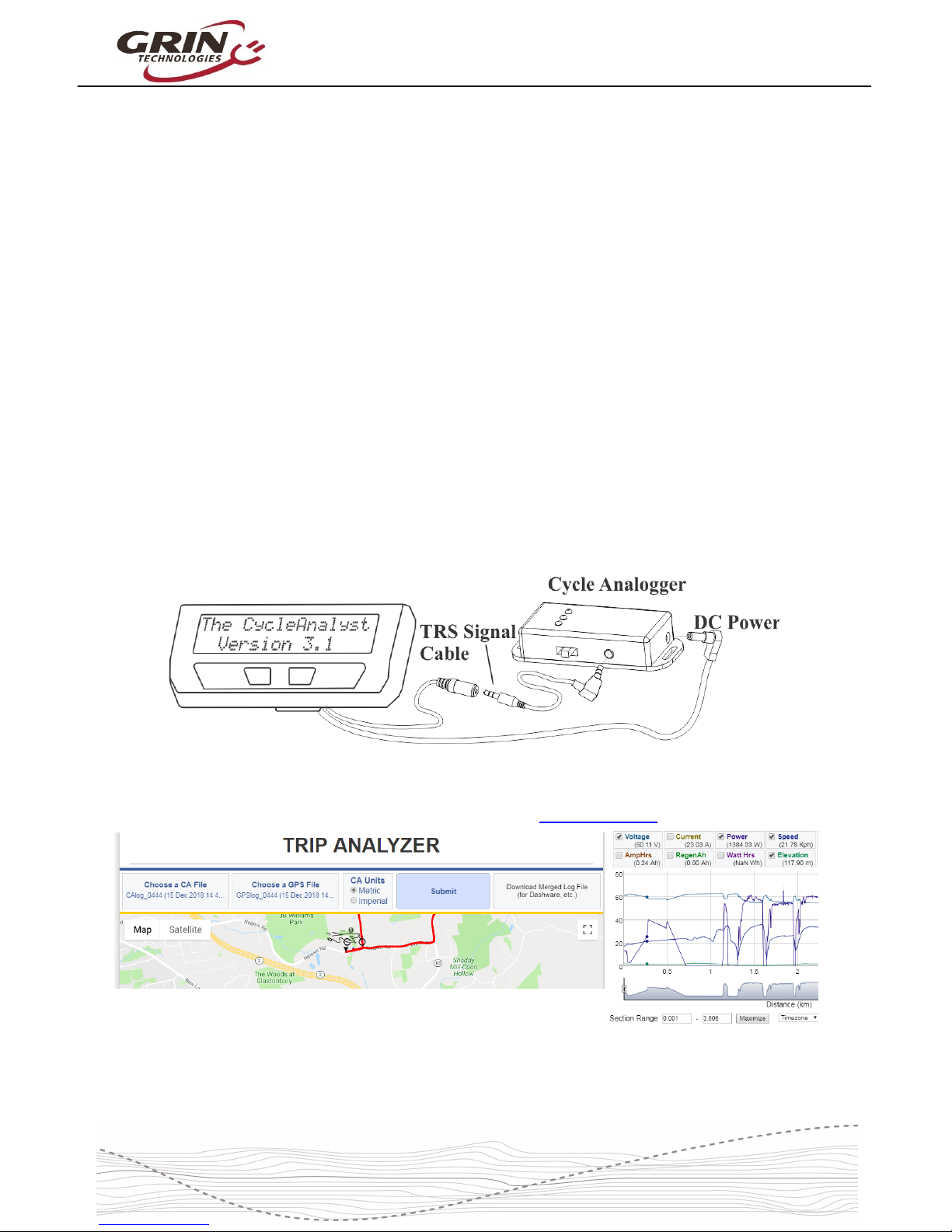
are available on all platforms to display and log serial data. Grin does produce a
product (the Cycle Analogger) that is plug and play with CA devices and
conveniently logs data directly to an SD memory card along with optional GPS
data.
Recorded CA data (whether logged with the Analogger or any other means) can
then be analyzed and visualized online with our Trip Analyzer web application.
This web application also has the ability to upload and merge a corresponding
NMEA encoded GPS file to show your consumption at various points on a trip.
32
Page 33

Cycle Analyst V3.1 User Manual
Rev 1.0
8 Software Setup Utility
The Cycle Analyst Setup Utility software is available for Windows, MacOS, and
Linux, and it lets you edit all the CA3 parameters by computer rather than
through the two button interface. The software also allows you to update and
reflash the firmware on the Cycle Analyst, and load various special purpose
firmwares like the Solar CA code or GPS code.
The software suite and instructions for using it are both on the CA3 info page
https://www.ebikes.ca/product-info/cycle-analyst-3.html
Even if the software utility is not used for flashing new settings on your device, it
is still useful as a reference for learning in greater detail the function of each and
every setting on your CA. There is a detailed tooltip that will show up when you
hover the mouse over any setting of interest, and these can be seen all in one file
by going Help->Help
There are certain items that can't be changed from the device and do require the
software tool. These are in the OEM category, and include the abillity to hide
items inside the setup menu itself and also set a total upper bounds for the
maximum power, speed, and current limits that the user can configure.
33
Page 34

Cycle Analyst V3.1 User Manual
Rev 1.0
9 Common Mistakes
The Cycle Analyst is pretty rugged and (we like to think) pretty self-explanatory.
But there are several user errors that have come up more often than others and it
is best to bring attention to these common mistakes upfront.
1. Connecting throttle to controller and not the CA3: If the throttle is left
plugged into the controller, then the CA's throttle output will be at the
minimum output and will over-ride the connected throttle. This results in no
power or very little power when the throttle is turned.
2. Hooking up a PAS sensor not able to handle 10V: The power on the 5pin PAS plug is 10V in order to be compatible with torque sensor models.
The Grin supplied PAS sensors have all been modified to handle 10V
power, but most third party PAS sensors can't. Hooking them up without
adding an inline 5V regulator will typically fry the PAS sensor. It can also
damage the CA too, if while failing it draws excessive current from the 10V
power bus.
3. Connecting a programming header to PAS plug: Certain models of 3rd
party motor controller use a 5-pin JST plug for controller programming, and
when this is mistakenly plugged into a Cycle Analyst PAS plug it shorts out
the 10V bus and damages the CA similar to item 2.
4. Using a torque sensor on a high voltage system: Even though the CA
on its own can handle up to 150V, this voltage needs to be derated when
accessories are plugged in which draw significant current. Most torque
sensors consume at least 20mA from the CA's 10V power bus, and that
usually correlates to no more than 52V nominal battery packs. A torque
sensor can be used with a high voltage ebike system if the power for the
torque sensor is supplied externally and not through the 10V on the PAS
plug.
5. Not reading the web page, manual, software tooltips, or our YouTube
videos and making a bunch of random ill-informed changes: Yeah,
this happens pretty often too. Luckily in the V3.1 firmware it's possible to
restore all settings back to factory defaults in the Miscellaneous setup
menu. Choose Misc->Defaults and then select Restore.
34
Page 35

Cycle Analyst V3.1 User Manual
Rev 1.0
10 Enjoy your Ride and Remember to Reset
That's it! After 34 pages of study, we hope that this Version 3.1 Cycle Analyst lets
you not only achieve the performance behavior you want from your ebike, but
that in using it you gain a new level of understanding on how ebike systems in
general work and operate. That more than anything is our mission with this
product.
And please don't forget to RESET YOUR CA ever time you have a fresh full
charge on the battery. That's essential to get the most from this device, and you
want to make it a second-nature habit.
35
Page 36

Cycle Analyst V3.1 User Manual
Rev 1.0
11 Specifications
11.1.1 Cables and Connectors
JST-SM connector series for signal lines. DC Power is 5.5x2.1mm.
11.1.2 Electrical
Voltage Range 10-150V, but derated by accessory current draw. With
common torque sensors on PAS plug, 60V max.
Voltage Resolution 0.1V
Device Current 10mA
Current Sense Range ±240 mV/Rshunt. For instance, with a 2mΩ sense resistor,
the maximum current is 120 amps. With a 0.5mΩ resistor,
up to 480 amps, and so forth
Current Resolution 0.01A in low range mode, 0.1A in high range mode
11.1.3 Mechanical
Dimensions 129 x 57 x 25 mm
Weight 270 g
11.1.4 Certifications
This device is CE compliant for use with 60V or lower
ebike systems
36
 Loading...