

Page 1
Technical manual
to be saved
by th e user
for future reference
Document n° 1049-2 ~ 04/11/2002
Société Industrielle de Chaudières
F 59660 Merville - FRANCE
Phone : 03.28.43.43.43
Fax : 03.28.43.43.99
RC Hazebrouck Siren 440 555 886
Subject to modifications
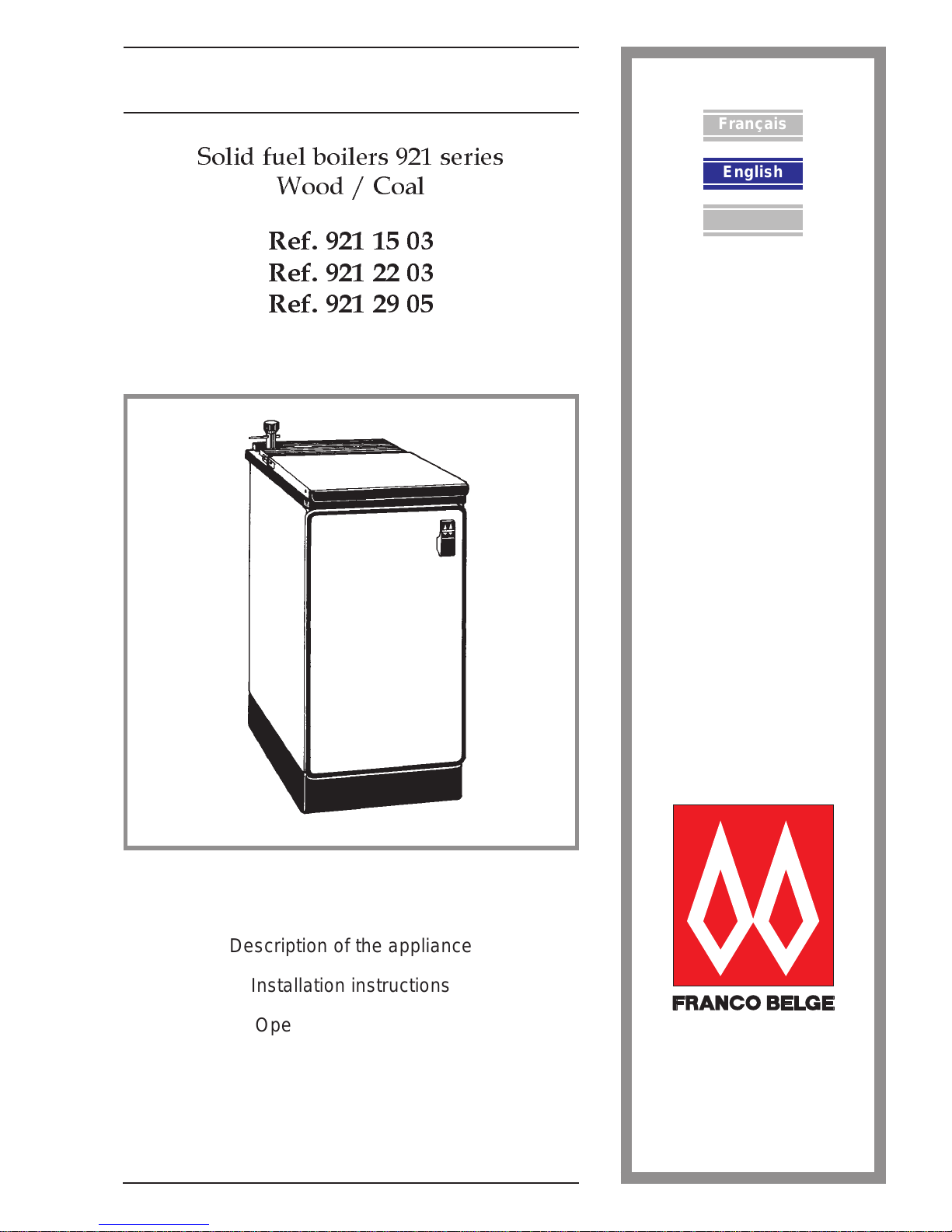
Grillon
Solid fuel boilers 921 series
Wood / Coal
Ref. 921 15 03
Ref. 921 22 03
Ref. 921 29 05
Français
English
Description of the appliance
Installation in structions
Operating instructions
Spare par ts
Warranty certificate
Italiano
Page 2
Package . . . . . . . . . . . . . . . . . . 3
Optional equipment . . . . . . . . . . . . 3
Specifications . . . . . . . . . . . . . . . 3
Description of the appliance. . . . . . . . 4
Sizing the boiler . . . . . . . . . . . . . . 4
Assembly and installation . . . . . . . . . . . . . . . . . . . . . . . . . . . . . . . . . . 4
Positioning the appliance . . . . . . . . . 4
The chimney . . . . . . . . . . . . . . . . 4
Connection to chimney . . . . . . . . . . 5
Assembling and installing the thermostat 5
Connecting the central heating circuit . . 5
Operating instructions . . . . . . . . . . . . . . . . . . . . . . . . . . . . . . . . . . . . 7
Check before lighting . . . . . . . . . . . 7
Lighting . . . . . . . . . . . . . . . . . . . 7
Heating . . . . . . . . . . . . . . . . . . . 8
Fuel . . . . . . . . . . . . . . . . . . . . . 8
Flue draught control box . . . . . . . . . . 8
Summer grates (optional) . . . . . . . . . 8
Maintenance . . . . . . . . . . . . . . . . 9
Fault diagnosis. . . . . . . . . . . . . . . 9
Spare parts . . . . . . . . . . . . . . . . . . . . . . . . . . . . . . . . . . . . . . . . . . 11
CONTENTS Page Page
FRANCO BELGE congratulates you on your choice.
FRANCO BELGE, which has been granted the ISO 9001 certification, guarantees the
quality of its appliances and is committed to meet its customers needs.
FRANCO BELGE, which can boast a 75-year experience in the industry of heating devices,
uses state-of-the-art technologies
to design and manufacture its whole range of products.
This document contains instructions on how to install your appliance and and make full
use of its functions, both for your comfort and safety.
Grillon - ref. 9211503 - 9212203 - 9212905
2 Technical manual "1049"
Page 3
1.Description of the unit
1.1. Package
1 package : Boiler unit with jacket
1.2.Optional equipment
- Summer wood grate.
- Summer coal grate.
- White color cover.
- Draught control box
1.3.
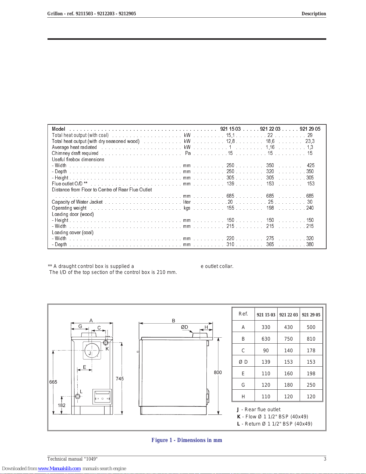
Specifications
Model .......................................... 9211503.....9212203.....9212905
Total heat o utput (with coal)
.................... kW......... 15,1.........22.........29
Totalheatoutput(withdryseasonedwood) ........... kW.........12,8........ 18,6 ....... 23,3
Averageheatradiated ....................... kW ..........1 ........ 1,16 ........1,3
Chimneydraftrequired ....................... Pa..........15.........15......... 15
Useful firebox dimensions
-Width ................................mm ......... 250........ 350 ....... 425
-Depth................................mm ......... 250........ 320 ........350
-Height................................mm......... 305........ 305 ........305
FlueoutletO/D** ..........................mm......... 139........ 153 ....... 153
Distance from Floor to Centre of Rear Flue Outlet
....................................mm ......... 685........ 685 ........685
CapacityofWaterJacket......................liter..........20 .........25.........30
Operatingweight ..........................kgs......... 155........ 198 ........240
Loading door (wood)
-Height................................mm......... 150........ 150 ........150
-Width ................................mm ......... 215........ 215 ........215
Loading cover (coal)
-Width ................................mm ......... 220........ 275 ........320
-Depth................................mm ......... 310........ 365 ........380
Figure 1 - Dimensions in mm
** A draught control box is supplied as standard to fit to the top flue outlet collar.
The I/D of the top section of the control box is 210 mm.
Ref.
921 15 03 921 22 03 921 29 05
A 330 430 500
B 630 750 810
C 90 140 178
Ø D 139 153 153
E 110 160 198
G 120 180 250
H 110 120 120
J - Rear flue outlet
K - Flow Ø 1 1/2" BSP (40x49)
L - Return Ø 1 1/2" BSP (40x49)
DescriptionGrillon - ref. 9211503 - 9212203 - 9212905
Technical manual "1049" 3
Page 4
1.4.Description of the appliance.
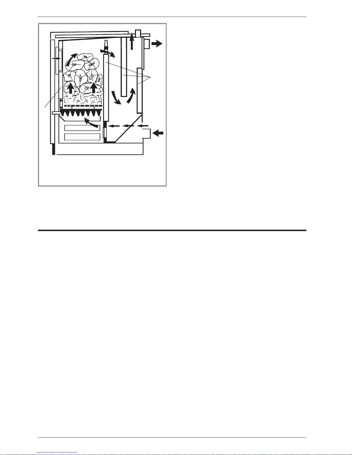
The Franco Belge 921 series boilers are designed to
burn solid fuel, wood and peat.
The heat exchanger is manufactured from high quality
plate steel. Its specific design provides a large surface
area for efficient use of the heat generated. The large
toploadingplatesenablelargepiecesoffueltobeburnt
whilst facilitating easy access for cleaning.
Regulation of the fire is by a water-sensing thermostat
which controls the primary air flow rate. Primary air is
introduced at the bottom of the heat exchanger. Fixed
secondary air outlets at thetop of thefire box introduce
a constant supply of additional air to assist combustion
of the flue gases.
The appliance is fitted w ith externaly controlled riddling
grate.
1.5.Sizing the boiler
All models are rated in BTU/hr output and should be
sized to the heat loss of the building.
If appliance is undersized, it will not be capable of
producing sufficient heat for the system. Oversizing will
result in excessive hot water productionand expansion
and serious chimney congestion problems could occur
especially when burning wood.
2.Assembly and installation
Please read through completely before
commencing installatio n.
The installation should be carried out by a qualified
heating e ngineer who is experienced in solid fuel
heating.
The installation must be in accordance with the current
codes of practice relating to the installation of solid fuel
appliances.
2.1.Positioning the appliance
The room in which the appliance is to be installed must
satisfy Current Building Regulations.
Thesewillstipulateanadequatefreshairinletofatleast
350 cm
2
. This must be installed in such a way, that in
adverse wind conditions the air flow cannot be reversed
as this may suck air out of the room in which the unit is
installed.
The position of the boiler will be determinedby the best
position for the chimney, whilst ensuring that a safe
distance is left between the boiler and combustible
surfaces.
2.2.The chimney
The chimney is the key to a successful installation and
the following key areas should be checked.
Height
The minimum height should be 5 metres with the
terminal at least 1 metre from the roof surface and in a
clear area away from possible downdraft. If in doubt
always increase the chimney height. This will help to
ensure an adequate draft and clearance of the flue
gases from the area of the building.
Insulation
The chimney needs to be warm from bottom to top and
should be adequatelyinsulated. Cold chimney and cool
flue gas temperature will result in tar formation and
smoke emission into the room.
Resistance
If the chimney has a horizontal section at the appliance
outlet, this should not exceed 30 cm. Any changes in
direction should be gradual (15 degrees maximum) and
thechimneysystemmustnotincorporatemorethantwo
bends. The straighter the chimney, the less resistance.
Any resistance will slow down the flue gases and help
to create a build up of tar deposits.
Draft
The appliancerequiresa draft of between 10 and20Pa
to burn effectively. This is the up draft of air through the
appliance. It is the result of the height of the chimney
and heating of the column of air within the chimney. An
inadequate draft will cause soot and tar formation in the
chimney.
The appliance requires a class 1 chimney. Existing
unlined chimneys should be lined with a liner suitable
for use with solid fuel burning appliances. If there is no
existing chimney, there are a variety of prefabricated
systems available and it is recommended to discuss
your particular application with a chimney specialist.
1
2
3
5
4
2
Figure 2 - Side cross section
1 - Secondary air inlet.
2 - Water circulation.
3 - Water return.
4 -Primaryairinlet.
5 - Water flow.
Assembly and installationGrillon - ref. 9211503 - 9212203 - 9212905
4 Technical manual "1049"
Page 5
2.3.Connection to chimney
•TOPFLUEOUTLET
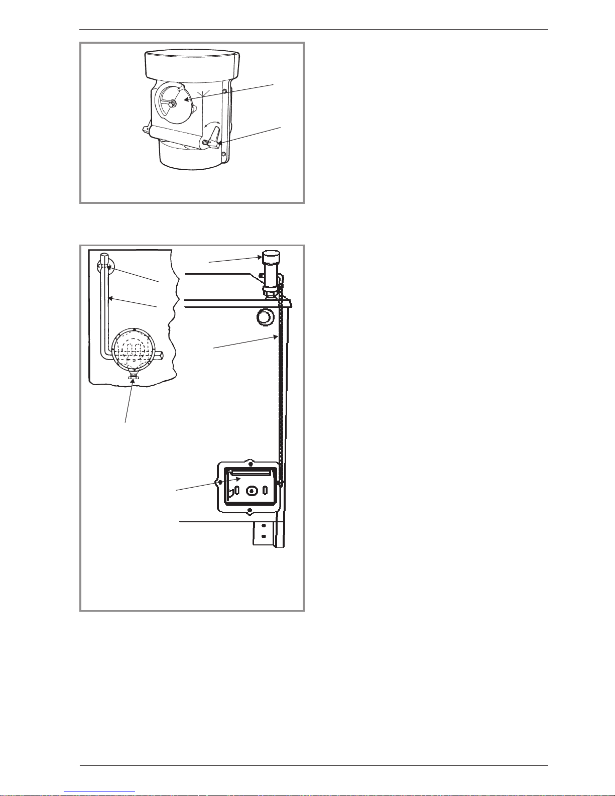
Use the draught control box (ill. 3).
The draught control box can be dismantled to give
access for flue cleaning.
•REAR FLUE OUTLET.
It is not possible to use the draught control box in this
position. Provision should therefore be made to fit a
draught regulator.
Important ! Don’t forget to fit with an airtight seal the
flue collar and the blanking plate which are supplied
and packed in the firebox.
Caution : Sufficient access must always be left for
chimney sweeping and appliance cleaning.
2.4. Assembling and installing the thermostat
Figure 4
The thermostat is fitted to the threaded tapping at the
left-hand corner of the appliance. Screw in the
thermostatusing a sealant to make the jointwater-tight.
Be careful not to damage the thread by over tightening.
The chain provided with the thermostat, should be
attached to the thermostat arm and the arm fitted into
the thermostat and held in place with the hexagonal
screw. The other end of the chain can then be
connected to the draught flap positioned at the bottom
rear corner of the appliance. It will be necessary to
adjust the length of the chaininorderthatthe automatic
draughtoperationfunctionscorrectly.However,thiscan
only be done when the appliance is lit.
When the appliance is working satisfactorily and the
circulating water is at a suitable temperature, say 60°C
adjust the thermostat. Fix the pipe thermometer onto
the outlet water pipe and observe the temperature.
Adjust the thermostat so that the white figure which
corresponds to the temperature is directly above the
white line. Cut the chain connecting the thermostat arm
to the air inlet flap and connect it up so that the a ir inlet
flap is just closed. When the temperature falls, the
thermostat arm will rise and open the air inlet flap to
increase the air flow. When the required temperature is
reached,the thermostat will close the air inlet and damp
down the fire. A finer adjustment is provided using the
threaded rod and locknuts toopen orclose the draught
flap by small amounts.
When the thermostat has been adjusted and the
desired water temperature reached, the manual
draughtcanbeclosed.Setthe thermostat tothedesired
temperature and allow it to control the fire.
It is important that the thermostat be positioned, as
shown in the diagram, with the small hexagonal screw
facing the front of the appliance.
2.5. Connecting the central heating circuit
In any installation relevant building codes of practices
must be observed.
•Theapplianceis not designed as a pressure vessel, so
the circuit must be left open to the atmosphere and
must not be constructed to allow any pressure build-up
to occur.
•A gravity circuit MUST be provided, as a fail safe heat
loss in the event of a circulating pump failure or a
power cut. To achieve this, ensure that large diameter
pipes leading to upstairs radiators have a direct flow
from the boiler, or install a large indirect domestic hot
water cylinder.
The layoutoftheheatingcircuitcanbedesignedinany
fashion that suits the house, as the pump will ensure
circulation of hot water to all points, but the hot water
cylinder or a small heating circuit must be engineered
to work by gravity. Use 1 inch I.D pipe (28 mm) to the
cylinder,insure thatthe cylinder has a 3/4 inch min. I.D.
coil wound from top to bottom, and that the inlet is
1
2
Figure 3
1 - Spinner air wheel. 2 - Damper control.
Flue draught control box for top flue outlet only
1
5
Figure 4 - Thermostat
4
2
3
6
1 - Shutter control air
inlet.
2 - Lever arm.
3 - Hexagon screw.
4 - Boring in the rear left
angle.
5 - Regulator
6 - Chain
Assembly and installationGrillon - ref. 9211503 - 9212203 - 9212905
Technical manual "1049" 5
Page 6
above the boiler and the outlet is above the return
tapping of the boiler.
•Anexpansioncylinderopentotheatmosphere must be
provided to ensure that no pressure build-up can
occur, and this should be connected to the highest
point of the circuit by 1". I.D. pipe (28 mm). If the
system is going to be left unattended during winter
periods, anti freeze shouldbe added. In the case of an
installation coupled to an automatic boiler, this should
not be necessary.
•In order to reduce the possibility of condensation
forming on the outside of the heat exchanger and on
the return water pipe, it will be necessary to ensure a
continuously high temperature to the return water.
Damage due to low temperature corrosion will
invalidate the guarantee. The return water should be
maintained above a minimum of 50°C.
•Thiscanbeachievedbyfittingapipethermostatonto
the return pipe from the domestic hot water cylinder
and by connecting this into the electric circuit
controlling the operation of the circulation pump on the
central heating circuit. The circulation pump can also
be controlled by a room thermostatand a time clock. If
this is not sufficient and the heat exchanger
temperature remains low, a fou r way mixing valve
should be fitted to thewateroutlet to bleed some water
straight back into the return. This valve can either be
operated manually or can be controlled electrically
from a thermostat on the return water pipe.
A pipe thermostat on the domestic hot water return has
the additional advantage of giving priority to this circuit
and ensures rapid reheatingof the domestic hot water.
This thermostat can be set at a fairly low temperature,
say 50°C, to give the best effect.
•TheFrancoBelgecanbefittedeitherinseriesorin
parallel with an existing boiler. However if it is fitted in
parallel ensure that it is not possible for the water to by
pass the heating circuit and to flow from one boiler to
theother.The thermostat on the oil or gas boilershould
be set to a lower setting than the Franco Belge to
ensure that, as the water temperature falls, heat is first
called for from the Franco Belge and only if it is not
capable of producing enough should the other boiler
switch in. This will ensure the most economical use of
fuel.
"
!
$
%
#
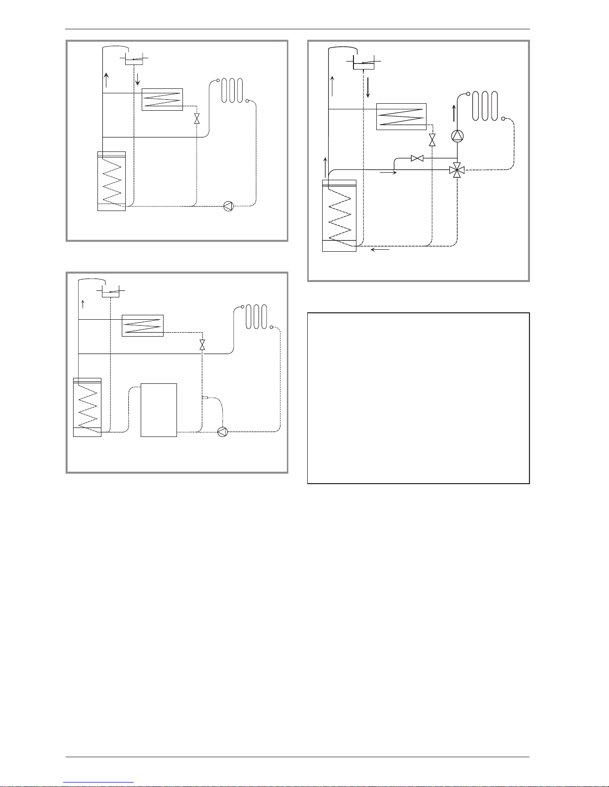
Figure 5 - Example of installation 1
"
!
$
%
#
&
'
Figure 6 - Example of installation 2
"
!
$
%
#
Figure 7 - Example of installation 3
Fig. 5, 6 and 7
1 - Expansion tank
2 - Water cylinder
3 - Franco Belge appliance
4 - Flow control valve
5 - Radiators cir cuit
6 - Sweep tee
7 - Circulating pump
8 - Pipe thermostat
9 - Oil or gas boiler
10 - Four way mixing valve
11 - Eventual minimal flow by-pass
Gravity hot water tank, pumped central heating.
Gravity hot water tank, pumped central heating linked
to existing oil or gas boiler, pipe thermostat fitted onto
return pipe from the tank.
Pumped central heating gravity hot water tank four
way mixing valve.
Assembly and installationGrillon - ref. 9211503 - 9212203 - 9212905
6 Technical manual "1049"
Page 7
3.Operating instructions
3.1.Check before lighting
•Be sure that your installer has tested the water circuit.
•Check that the cleaning access door is closed. It is
located behind the ash pan.
•Check that all the grates are in their correct positions
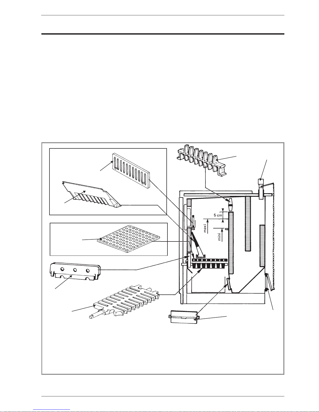
(fig. 8).
•Check the workingof the air inlet flap attheback of the
boiler (# 2 and # 3, fig. 8).
3.2.Lighting
The boiler is lit exactly like an ordinary fire, with paper,
and kindling. Open the ash pan door aircontrol to get a
good draught.
Once the fire is burning well, the boiler can be stocked
up with the fuel.
When the fire is well established and the flue is warm,
close the draught control wheel and allow the
thermostat to regulate the burning rate.
Do not allow the fire to get too hot during the first week.
All the cast iron parts need seasoning and should not
be heated too suddenly in the first few days.
If, when the appliance is first lit, black water leaks from
the firebox, this is a sign of the presence of
condensation on the wa ter jacket. If cond ensation
persists after a 48 hours period, consult your installer.
Caution : Ash pan door to be closed during operation
to prevent excessive temperature.
For coal burning only
For wood burning only
1
2
3
4
5
6
7
8
9
Figure 8 - Description of the appliance
1 - Flue guard grate
2 - Thermostat
3 - Controlled air inlet
4 - Cleaning flap behind ashpan
5 - Oscillating grate(s)
6 - Face plate
7 - Wood grate
8 - Inclined grate
9 - Coal retainer
Positioning of the grates
Operating instructionsGrillon - ref. 9211503 - 9212203 - 9212905
Technical manual "1049" 7
Page 8
3.3. Heati ng
The automatic thermostat control should be set to the
water temperature required i.e. if 60°C is required the
white figure 60 should be set oppositethe white line on
the thermostat body. Provided that the fire is stocked up
and the ash pan door draught flap is closed the
thermostat will automatically control the burning rate fo
the fire and produce the required temperature.
3.4. Fuel
Coal : Use of household coal, and coals which
disintegrateinheat are not recommanded nor are those
producing a large amount of ash. Smokeless fuel,
Anthracite or similar Smokeless fuels give the most
efficient performance
Wood : Use only well seasoned dry wood (at least two
year old and dried under cover for at least six months
before using). Serious damage to the boiler can occur
by using unseasoned wood.
Peat : This fuel, like wood, mustbeproperly dried.Ifthe
fuel is wet, the output will be considerably decreased
and appliance could sufferfrom corrosion.
Remarks about the use of fuels :
The amount of ash in the fire is a very important factor
in the performance of the Franco Belge.
When burning wood, a good base of ashes is
advantageous for slow controlled burning, but should
be reduced by riddlingbeforecooking,orwheneverash
accumulatestoo much and reduce the fire box capacity.
When burning coal or smokeless fuels, theash mustbe
riddled more frequently to allow a good airflow to the
fire. Solid fuel requires much more air to burn than
wood.
3.5.Flue draught control box
For Great Britain only (ill.3, page 5) :
The draught control box is designed to slow down the
flow of gases leaving the appliance and entering the
flue.
This is accomplished by restricting the square area of
the chimney. It causes the gases created in the
appliance to move slower and in so doing reduces the
amount of combustion air entering the unit. The result is
that the appliance will burn for longer periods.
The flue box has two controls : the spinner air wheel 1
and the damper control 2.
If it is found that the appliance is burning too fast,close
the flue damper 2 to one of the four positions. Trial and
error will determine which setting is best for your
situation.Whenexperimenting,start by putting the lever
in the top position and close it notch by notch, as
necessary.
Always remember to open the damper to a vertical
position before attempting to reload with fuel.
The air wheel 1 situated at the front of the flue box
should only be used if the damper gives insufficient
control. If this is the case, the air wheel may be opened
little by little until the desired result is obtained. The air
wheel must not be used for long periods and should be
closed before refuelling.
3.6.Summer grates (optional)
During the summer when the domestic hot water s upply
but not the central heating, is required, the appliance
should be used with the “Summer Grate”. This grate
rests on four lugs situated in the fire box and reduces
thesizeoffirebyapproximatelyhalf.
1
2
3
4
5
6
7
8
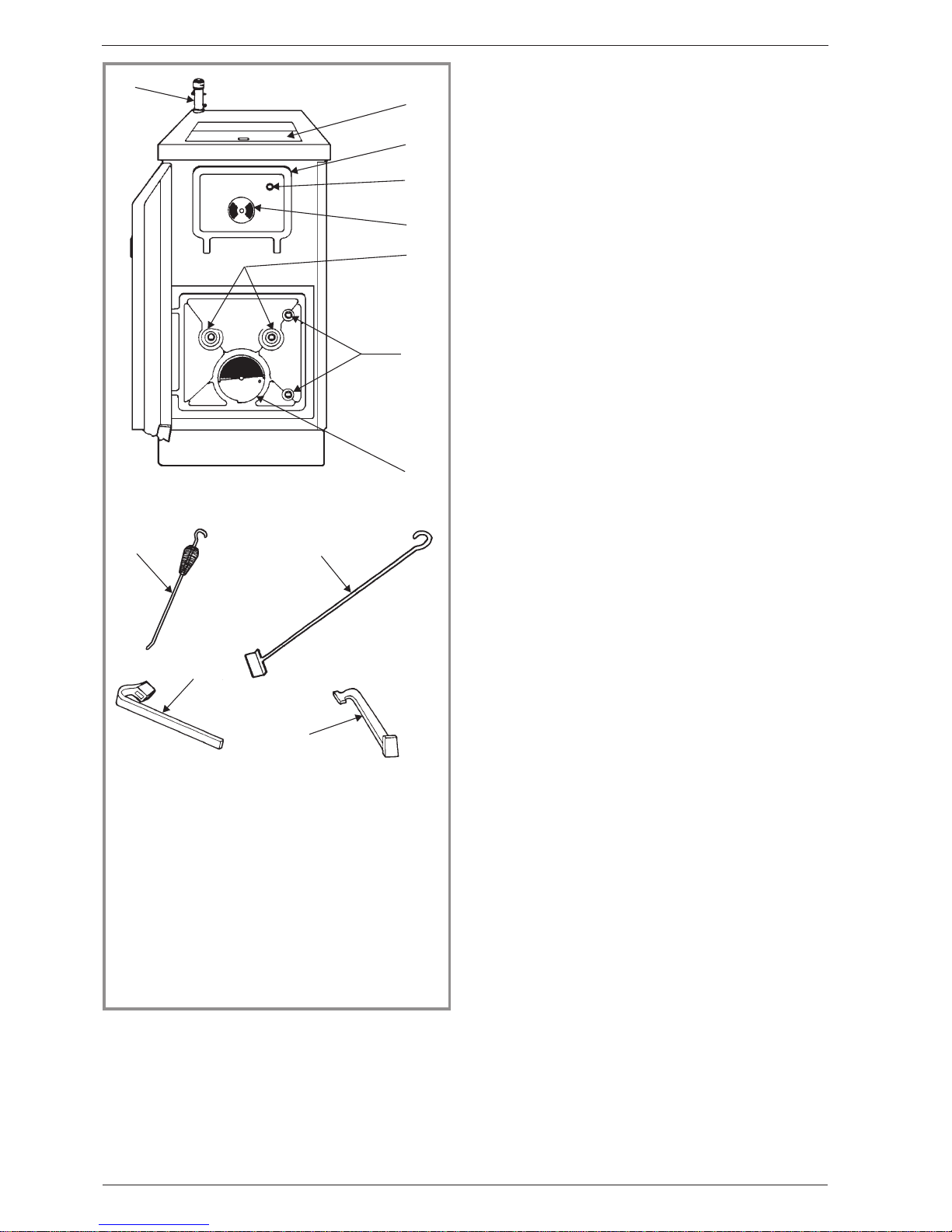
Figure9-Operatingdevices
9
10
11
12
1 - Thermostat.
2 - Loading door : “Coal”.
3 - Loading door :
“Wood”.
4 - To open the loading
door.
5 - Secondary air control.
6 -Toriddlethegrates
7 - To open the ash pan
door.
8 - Manual draught
control
9 - Poker
10 - Scraper for cleaning
and scraping fire box and
flue passages.
11 - Riddling handle for
deashing and for
opening ash pan door.
12 - Opening tool, for
handling ash pan, lifting
plate above fire box to
load.
Operating instruct ionsGrillon - ref. 9211503 - 9212203 - 9212905
8 Technical manual "1049"
Page 9
3.7.Maintenance
The appliance is most efficient when all the surfaces of
theheatexchangerandtheashcompartment are clean.
If soot and ashes are allowed to build up, the life of the
grates will be shortened, therefore it is essential to
emptytheashpan,ifnecessary, daily! Tarand soot build
up on the surfaces of the water jacket and flue
passages should be removed at frequent intervals. This
is best achieved by runningthe appliance very hotfor a
short period each day.
It is important to do this in order to preserve the life of
the water jacket.
3.8.Fault diagnosis.
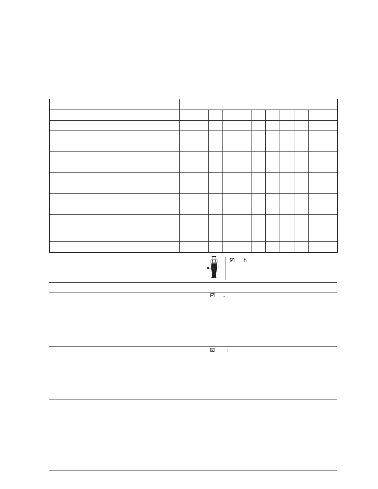
Situation Cause reference
Unresponsive fire
AG
Difficulty in maintaining fire
AEGHK
Fire goes out over night
AGI
Smoke an d smell in kitchen
AEF
Smoke emitted when loading
AF
Smoke emitted when door is slammed
E
Rapid sooting-up of chimney and flue ways
AGIJ
Fire burns out overnight
BK
Uncontrollable burning rate
CIK
Difficulty in obtaining w ater temperature
AGJK
Overnight burning performance dependent on weather
conditions
C
Moisture in ashpan and under boiler
D
Large amounts of clinker forming
BGJ
Cause reference Cause
- Action
A
¤ Inadequate draught
þ
- The chimney should be checked with a draught meter
and ifbelowthe recommended level,look for airleakor
a constantly cold chimney.
- If the connecting flue pipe terminates in a large
chimney and no evidence of a ir leaks can be
discovered. a chimney liner should be considered.
- If the inadequate draught is due to a poor geographic
position, consult your dealer to consider an electric
draft inducing fan.
B
¤ Excessive draught
þ
- If top fluethe appliance shouldhave been suppliedwith
a draught control box to help regulate the chimney
draught. If the control box gives inadequate control, fit
a draught stabiliser.
C
¤ Draught too variable
- This could be causedby a cold chimneywith excessive
heat loss but it is more likely that the cause is
turbulence at the chimney terminal.
Raise the height of the chimney or fit a suitable cowl.
D
¤ Condensation
- Condensation is often mistaken for a leaking water
jacket and can be very persistent. Each water jacket is
tested thoroughly in the factory and it is highly unlikely
that a leak could be the cause.
- Condensation is caused by :
- A poor chimney which allows the flue gases to cool
rapidly, therebycondensingsteam in theflue.Consider
lining chimney.
- Wetwood fuel being used. Dry andseasonwoodwell
before burning it. See section on fuels.
þ
: This sign means that you should
asked for a qualified engineer to do
the work.
Operating instructionsGrillon - ref. 9211503 - 9212203 - 9212905
Technical manual "1049" 9
Page 10

- The return water temperature being too low. To
minimise the possibility of condensation, always allow
your FRANCO BELGE to warm up slowly and never
operate thecirculatingpumpuntilthe systemisheating
with the return temperature no more than 15°C below
the flow temperature and in any case, no less than
50°C.
- If condensation still persists, allow the fire to burn
slowly forafull 24 hour periodheatingthe domestic hot
water only.Then try the pump again.
- If the return temperature is always 20°C below the
flow temperaturewiththepump on, it is likely thatthe4
way mixing valve is not being used correctly. This
indicates that insufficient hot water is being directed
into the return.
- Condensation normally appears only when the
system is first used and sometimes at the beginning of
the winter season when the heating is first put on. In
both cases, allow the heat to build up very slowly and
condensation will be kept to a minimum or not
experienced at all.
- Continual condensation will reduce the life of the
water jacket and invalidate your guarantee. It should
therefore be avoided at all costs.
- If condensation occurs after the pump has been
turned on, this will be due to theheatingcircuitcooling
the system too quickly. The solution is to switch off the
pump, allow the system toreheatfullyandturnononly
half the radiators when the pump is switched on.
Gradually, turn on the remainder of the radiators, one
by one, allowing plenty of time for the return water to
keep up temperature.
E
¤ Insufficient air entering kitchen
- See section “Positining the appliance”.
F
¤ Restriction in flue
þ
- Apparent if the appliance has normal flue draught and
reaches temperature quickly but smokes when being
loaded or when a large volume of air is admitted to the
fire (e.g. when ash pan door is opened).
Therestrictionmay beafall ofsootor masonryinwhich
case, chimney sweeping should cure the problem .
Alternatively, the problem may be caused by too many
bends whicharetoo acute in thechimneyconstruction.
G
¤ Fuels
- See section “Fuels”.
H
¤ Operator error
- By this, we mean that it may be that you need a little
more time to get used to your appliance.
- However,if you still have problems afterpersisting for
some time, please contact your dealer.
I
¤ Chimney construction
þ
- The chimney’s construction must comply with Current
Building Regulations.
- An inadequately insulated chimney will allow rapid
coolingofthe fluegases,causing excessivedepositsin
the chimney which will lead to condensation and
eventually smoke emission from the appliance.
J
¤ Rate of burning
- All FrancoBelge appliancesare designedtobe efficient
when burningslowly but theymustbe burnedhotfor 30
minutes after each slow burning period to prevent a
residual build up of tar/soot in the flue ways (normally
this would be achieved during cooking). However, you
must not operate your Franco Belge at maximum
output for excessively long periods.
K
¤ Thermostat failure
þ
- Whilst it is highly unlikelythat the thermostat would fail,
it is a possibility that should be investigated once the
other likely causes have been looked into.
- Contact your dealer.
Operating instruct ionsGrillon - ref. 9211503 - 9212203 - 9212905
10 Technical manual "1049"
Page 11

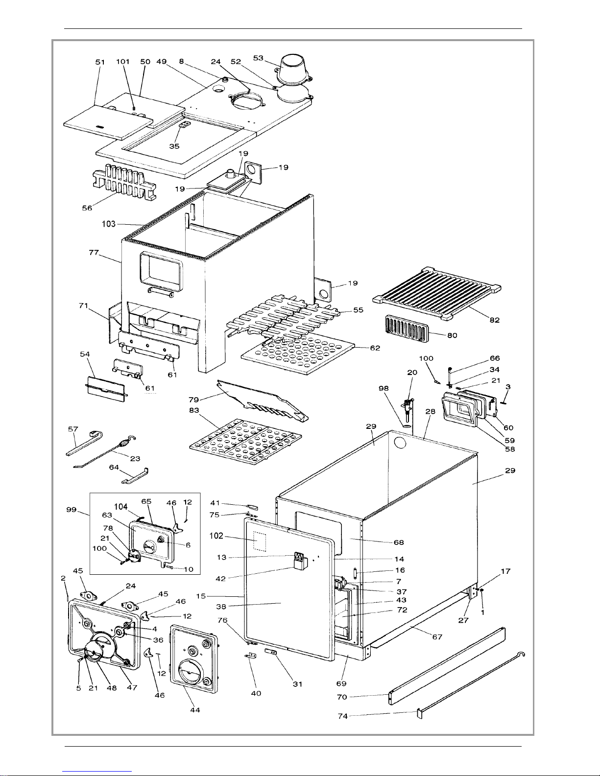
4.Spare parts
When ordering spare parts, specify the appliance type
and serial number, including the colour index (on the
guarantee or identification plate), the name of the part
and the part number.
Example : Grillon,Ref.:921 15 03 Z, side pan el
207706 30
A = 921 15 03 Z B = 921 22 03 Z C = 921 29 05 Z
N° Code Description............... Type............ A..... B......C ............Qty
1 100602 Snapclip..................................A..... B......C ............ 24
2 134701 Pin .................... 5x24.............A..... B......C ............ 02
3 100931 Axle ....................................A..... B......C ............ 02
4 100949 Axle ....................................A..... B......C ............ 02
5 100955 Axle ....................................A..... B......C ............ 01
6 100965 Axle ....................................A..... B......C ............ 01
7 101013 Magneticcatch ..............................A..... B......C ............ 01
8 101820 Ring ....................................A..... B......C ............01
10 110402 Hingepin ................ 6x30.............A..... B.................... 02
10 110403 Hingepin ................ 6x35...........................C ............ 02
12 134704 Pin.................... 5x38.............A..... B......C ............03
13 122809 Nameplate ................................A..... B......C ............ 01
14 123474 Trim ....................................A........................... 01
14 123476 Trim ..................................................C ............01
14 123478 Trim .......................................... B.................... 01
15 123475 Trim ....................................A........................... 01
15 123477 Trim ..................................................C ............01
15 123479 Trim .......................................... B.................... 01
16 134301 Strikingplate ...............................A..... B......C ............ 01
17 134501 Pushclip..................................A..... B......C ............ 12
19 159925 Protectionplate..............................A..... B......C ............ 04
20 164902 Regulator .................................A..... B......C ............ 01
21 166003 Spring ..................11x15.............A..... B......C ............ 03
23 180002 Poker....................................A..... B......C ............ 01
24 181607 Ceramicrope ..............Ø9,5.............A..........................1,00m
24 181607 Ceramicrope ..............Ø9,5................... B...................1,10m
24 181607 Ceramicrope ..............Ø9,5...........................C ...........1,30m
27 201000 60 Leg.....................................A..... B......C ............ 04
28 204107 Backpanel....................................... B....................01
28 204112 Backpanel...............................................C ............ 01
28 204114 Backpanel.................................A........................... 01
29 207706 30 Sidepanel.................................A........................... 02
29 207707 30 Sidepanel....................................... B.................... 02
29 207708 30 Sidepanel...............................................C ............ 02
31 209901 Protector..................................A..... B......C ............ 01
34 230000 Square...................................A..... B......C ............ 01
36 236105 Sealingplate ...............................A..... B......C ............ 02
37 241804 Magnetsupport ..............................A..... B......C ............ 01
38 252579 AL Frontpanel ..............................................C ............ 01
38 252580 AL Frontpanel ...................................... B.................... 01
38 252581 AL Frontpanel ................................A........................... 01
40 273306 64 Hinge....................................A..... B......C ............ 01
41 273408 64 Hinge....................................A..... B......C ............ 01
42 300983 64 Handle...................................A..... B......C ............ 01
43 301010 60 Frame ...................................A........................... 01
43 301011 60 Frame ......................................... B.................... 01
43 301012 60 Frame .................................................C ............01
44 301113 60 Ashpandoor .............................................C ............ 01
44 301135 60 Ashpandoor ...............................A........................... 01
44 301136 60 Ashpandoor ..................................... B.................... 01
45 301304 60 Clamp ...................................A..... B......C ............ 02
46 301521 Doorlock .................................A..... B......C ............ 03
48 301711 60 Airdamper.................................A..... B......C ............ 01
49 702115 80 Topplate..................................A........................... 01
49 702116 80 Topplate........................................ B.................... 01
49 702117 80 Topplate................................................C ............ 01
49 302134 80 Completetopplate ............................A........................... 01
49 302135 80 Completetopplate .................................. B....................01
49 302140 80 Completetopplate ..........................................C ............ 01
50 302311 80 Topplate..................................A........................... 01
50 302312 80 Topplate........................................ B.................... 01
50 302322 80 Topplate................................................C ............ 01
51 302407 80 Topplate..................................A........................... 01
51 302408 80 Topplate........................................ B.................... 01
51 302413 80 Topplate................................................C ............ 01
52 303713 80 Blankingplate...............................A........................... 01
Spare partsGrillon - ref. 9211503 - 9212203 - 9212905
Technical manual "1049" 11
Page 12
12 Technical manual "1049"
Spare partsGrillon - ref. 9211503 - 9212203 - 9212905
Page 13

52 303714 80 Blankingplate..................................... B......C ............ 01
53 303818 60 Fluecollar.................................A........................... 01
53 303819 60 Fluecollar....................................... B......C ............ 01
54 305911 Accesscover ...............................A........................... 01
54 305912 Accesscover ..................................... B......C ............ 01
55 3067 04 Oscillating grat e ..............................A........................... 01
55 3067 05 Oscillating grat e .................................... B.................... 02
55 3067 06 Oscillating grat e ............................................C ............ 02
56 307102 Flueguard.................................A........................... 01
56 307103 Flueguard....................................... B.................... 01
56 307104 Flueguard...............................................C ............ 01
57 307105 60 Riddlinghandle..............................A..... B......C ............ 01
58 307202 60 Frame ...................................A..... B......C ............ 01
59 307301 60 Door ....................................A..... B......C ............ 01
60 308201 60 Supplementarydoor ...........................A..... B......C ............ 01
61 309101 Faceplate.................................A........................... 01
61 309102 Faceplate....................................... B.................... 01
61 309103 Faceplate...............................................C ............ 01
62 309202 Woodgrate ................................A........................... 01
62 309204 Woodgrate ..............................................C ............ 01
62 309206 Woodgrate ...................................... B.................... 01
63 309945 60 Maindoor .................................A..... B......C ............ 01
64 312803 60 Handtool .................................A..... B......C ............ 01
65 314606 60 Innerpanel ................................A..... B......C ............ 01
66 459200 Controlrod.................................A..... B......C ............ 01
67 600100 20 Base.......................................... B.................... 01
67 600103 20 Base..................................................C ............ 01
67 600105 20 Base....................................A........................... 01
68 600349 20 Frontplate.................................A........................... 01
68 600350 20 Frontplate....................................... B.................... 01
68 600351 20 Frontplate...............................................C ............ 01
69 600400 09 Plinth....................................A........................... 01
69 600422 09 Plinth.......................................... B.................... 01
69 600425 09 Plinth..................................................C ............ 01
70 600501 09 Plinth....................................A........................... 02
70 600502 09 Plinth.......................................... B.................... 02
70 600503 09 Plinth..................................................C ............ 02
71 633407 Boiler support..............................................C ............ 01
71 633403 Boilersupport...............................A........................... 01
71 633404 Boilersupport..................................... B.................... 01
72 624008 Ash-pan ..................................A........................... 01
72 624009 Ash-pan ........................................ B.................... 01
72 624010 Ash-pan ................................................C ............01
74 858003 60 Scraper ..................................A..... B......C ............01
75 900912 64 Hinge....................................A..... B......C ............ 01
76 900913 64 Hinge....................................A..... B......C ............ 01
77 910945 Waterjacket................AV .............A........................... 01
77 910946 Waterjacket................AV ................... B.................... 01
77 910947 Waterjacket................AV ...........................C ............ 01
78 301713 60 Airdamper.................................A..... B......C ............ 01
79 307404 Inclinatedgrate ..............................A........................... 01
79 307405 Inclinatedgrate .................................... B.................... 01
79 307406 Inclinatedgrate ............................................C ............ 01
80 307423 Fuelretainer................................A..... B......C ............01
98 167510 Airdamper.................................A..... B......C ............ 01
99 988791 Completedoor...............................A..... B......C ............ 01
100 189103 Screw ..................27x8x6 ............A..... B......C ............ 01
101 189118 Screw .................. d.10.............A..... B......C ............ 01
103 181611 Ceramicrope .............. Ø20.............A..... B......C ...........1,50m
104 181619 Ceramicrope .............. Ø12.............A..... B......C ...........0,75m
Spare partsGrillon - ref. 9211503 - 9212203 - 9212905
Technical manual "1049" 13
Page 14
❧ Warranty certificate ❧
❧ Legal warranty
Our products are guaranteed for twelve months against any
defect, flaworimperfection.Duringthis time, all parts judged
defective by our Warran ty control department ma y be
replaced in our workshops. Incidentalcostsoftransportation
and packing payable by the buyer.
Some parts or components have a longer warranty period :
- Cast-iron shell of boiler : 3 years
- Steel shell of boiler : 3 years
- Removable or independent stainless steel hot water
cylinder : 5 years
- Independent enamelled steel hot water cylinder : 3 years
- Incorporated circulating pump : 2 years.
❧ Terms of the warranty
This warranty is only valid if :
- The unit has been installed and checked by a professional
installer before operating,
- All installation and adjustment instructions listed in the
technical manual supplied with the unit have been followed,
- All operation and maintenance instructions have been
followed.
❧ This warranty does not cover:
- Lamps, fuses, spark plugs, cast iron parts directly in
contact with burning coal and wood, firebricks, flue baffles,
glasses .
- Any damage resulting from the use of fuel not
recommended in our instructions ;
- Parts which are damaged by external causes such as
unadapted chimneys, thunderstorms, damp, faulty pressure
or fail in pressure, thermic anomalies, explosions, etc...
- Electrical parts which are deteriorated by any connection
or use on a supply circuit with voltage within 10% of the
indicted voltage (230 V in EU).
Material subject to modifications without prior notice. This
manual does not engage the responsibility of
FRANCO BELGE.
*
Nameandaddressoftheinstaller: _____________________________
______________________________________________
(
Telephone: _______________________________________
*
Name and address of the customer : _ _ _ _ _ _ _ _ _ _ _ _ _ _ _ _ _ _ _ _ _ _ _ _ _ _ _ _
______________________________________________
Dateofinstallation: ____/____/________
Model of the appliance :
Color :
Serial number : ___ ___ ___ ___ ___ ___
• This certificate has to be completed and kept carefully.
In case of claims, send a copy of this to :
Franco Belge, Société Industrielle de Chaudières, rue Orphée Variscotte, 59660 MERVILLE, FRANCE.
q
: 921 15 03
q
: 921 22 03
q
: 921 29 05
q
:Z
 Loading...