

GrillMaster 720-0894A User Manual
19000479A0
LP Gas Grill page 1-31
PARRILLA A GAS PROPANO pagina 3264
GRIL AU GAZ DE PÉTROLE LIQUÉFIÉ
page65-95
WARNING
To reduce the risk of fire, burn hazard or other injury,
read the manual carefully and completely before
using your grill.
WARNING
FOR OUTDOOR USE ONLY.
WARNING
This grill is not intended to be
installed in or on recreational
vehicles and/or boats.
Example only: SERIAL #__________MFG. DATE___________PURCHASE DATE:_______________
Questions, problems, missing parts? Before returning to your retailer, call our customer service
department at 1-800-913-8999 in USA, 8 a.m. - 5 p.m., PST, Monday - Friday
MODEL / MODÈLE / MODELO # 720-0894A
Warranty-----------------------------------------------Safety Precautions-------------------------------Lighting Instructions---------------------------Package Content List----------------------------Hardware Contents---------------------------------Preparation-------------------------------------------Parts Diagram --------------------------------------Parts List----------------------------------------------Assembly Instructions---------------------------
Cooking Instruction----------------------------------
Cooking Chart----------------------------------------Cleaning and Maintenance-------------------------Troubleshooting--------------------------------------
Table of Contents
2
3
6
8
10
10
11
12
13
28
29
30
31
Warranty
2
LIMITED WARRANTY
One Year Limited Warranty
When installed, operated and maintained according to all supplied
instructions, if this appliance fails due to a defect of purchase, call 1-800913-8999 to arrange for free repair or replacement if repair is unavailable.
For one year from the date of purchase, any burner that rust through will be
replaced free of charge. After the first year from the date of purchase, you
are responsible for the labor cost to have it installed.
All warranty coverage excludes igniter batteries and grill part paint loss,
discoloration or surface rusting, which are either expendable parts that can
wear out from normal use within the warranty period, or are conditions that
can be the result of normal use, accident or improper maintenance.
All warranty coverage is void if this product is ever used while providing
commercial services or if rented to another person.
This warranty covers ONLY defects in material
And workmanship. Manufacturer will NOT pay for:
1.Expendable items that can wear out from normal use within the warranty
period, including but not limited to batteries, light bulbs and surface coatings
or finishes.
2. A service technician to instruct the user in correct product installation,
operation or maintenance.
3. A service technician to clean or maintain this product.
4. Damage to or failure of this product if it is not installed, operated or
maintained according to the all instructions supplied with the product.
5.Damage to or failure of this product resulting from accident, abuse, misuse
or use for other than its intended purpose.
6. Damage to or failure of this product caused by the use of detergents,
cleaners, chemicals or utensils other than those recommended in all
instructions supplied with the product.
7. Damage to or failure of parts or systems resulting from unauthorized
modifications made to this product.
Disclaimer of implied warranties; limitation of remedies
Customer’s sole and exclusive remedy under this limited warranty shall be
product repair as provided herein. Implied warranties, including warranties of
merchantability or fitness for a particular purpose, are limited to one year or
the shortest period allowed by law. Manufacturer shall not be liable for
incidental or consequential damages. Some states and provinces do not
allow the exclusion or limitation of incidental or consequential damages, or
limitation on the duration of implied warranties of merchantability or fitness,
so these exclusions or limitations may not apply to you.
This warranty applies only while this appliance is used in the United States.
This warranty gives you specific legal rights, and you may also have other
rights which vary from state to state.
Keep this manual for future reference.
Conserve el presente manual para consultas futuras.
Conserver ce manuel à titre de référence ultérieure.
State of California Proposition 65 Warnings:
WARNING: This product contains one or
more chemicals known to the State of
California to cause cancer.
WARNING: This product contains one or
more chemicals known to the State of
California to cause birth defects or other
reproductive harm.
In the State of Massachusetts, the following
installation instructions apply:
Installations and repairs must be
performed by a qualified or licensed
contractor, plumber, or gasfitter qualified or
licensed by the State of Massachusetts.
If using a ball valve, it shall be a T-handle
type.
A flexible gas connector, when used, must
not exceed 3 feet.
WARNING
Failure to comply with these instructions could result in a
fire or explosion that could cause serious bodily injury,
death, or property damage.
WARNING
Your grill will get very hot. Never lean over the
cooking area while using your grill. Do not touch
cooking surfaces, grill housing, lid or any other grill
parts while the grill is in operation, or until the gas grill
has cooled down after use.
Failure to comply with these instructions may
result in serious bodily injury.
WARNING
1. Do not store or use gasoline or other
flammable liquids or vapors in the
vicinity of this or any other appliance.
2. An LP cylinder not connected for use
shall not be stored in the vicinity of this
or any other appliance.
DANGER
If you smell gas:
1. Shut off gas to the appliance.
2. Extinguish any open flame.
3. Open lid.
4. If odor continues, keep away from the
appliance and immediately call your gas
supplier or your fire department.
Grill Installation Codes
The installation must conform with local codes or, in the
absence of local codes, with either the national fuel gas
code, ANSI Z 223.1/NFPA S4, Natural gas and propane
installation code, CSA B149.1, or propane storage and
handling code, B149.2, or the standard for Recreational
vehicles, ANSI A 119.2, and CSA Z240 RV series
recreational vehicle code, as applicable.
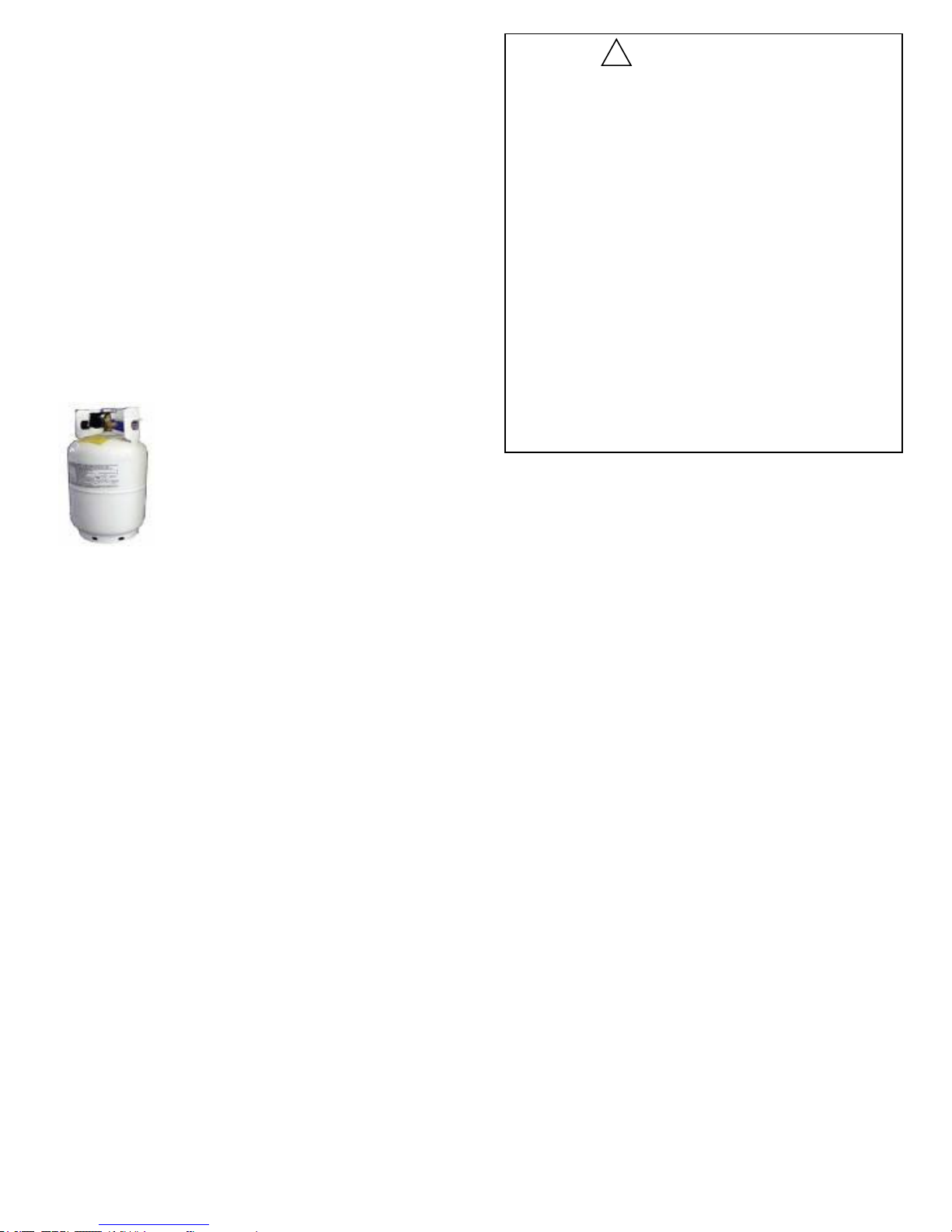
LP gas grill models are designed for use with a
standard 20 lb. Liquid Propane Gas tank, not included
with grill. Never connect your gas grill to an LP gas tank
that exceeds this capacity.
!
!
Precautions
!
!
A tank of approximately 12 inches in diameter by 18-1/2 inches
high is the maximum size LP gas tank to use.
You must use an OPD gas tank which offers an Overfill
Prevention Device.
This safety feature prevents the tank from being overfilled
which can cause malfunction of the LP gas tank, pressure
regulator and/or grill.
The LP gas tank must be constructed and marked in
accordance with specifications of the U.S. Dept. of
Transportation (DOT). In Canada, the LP gas tank must meet
the National Standard of Canada ,CAN/CSA-B339 , Cylinders ,
spheres and Tubes for Transportation of Dangerous Goods
and Commission .
1. The LP gas tank must have a shutoff valve, terminating in an
LP gas supply tank valve outlet, that is compatible with a Type
1 tank connection device. The LP gas tank must also have a
safety relief device that has a direct connection with the vapor
space of the tank.
2. The tank supply system must be arranged for vapor
withdraw.
3. The LP gas tank used must have a collar to protect the tank
valve.
Proper Placement and Clearance of Grill
Never use your gas grill in a garage, porch, shed, breezeway
or any other enclosed area. Your gas grill is to be used
outdoors only, at least 24 inches from the back and side of
any combustible surface. Your gas grill should not be used
under overhead combustible construction . Do not obstruct the
flow of ventilation air around the gas grill housing.
• Do not install this outdoor gas grill in or on recreational
vehicles or boats
• Keep outdoor gas grill area clear and free from combustible
materials, gasoline and other flammable vapors and liquids
• Do not obstruct the flow of combustion and ventilation air.
Check for this each time prior to using grill.
• Never connect an unregulated LP gas tank to your gas grill.
The gas pressure regulator assembly supplied with your gas
grill is adjusted to have an outlet pressure of 11” water column
(W.C.) for connection to an LP gas tank.
• Only use the pressure regulator and the hose assembly
supplied with your gas grill. Replacement pressure regulators
and hose assemblies must be those specified in this manual.
3
• Have your LP gas tank filled by a reputable propane
gas dealer and visually inspected and re-qualified at
each filling.
• Do not store a spare LP gas tank under or
near this appliance.
• Never fill the tank beyond 80 percent full . If this
information is not followed exactly a fire causing death
or serious injury may occur.
• Always keep LP gas tanks in an upright position.
• Do not store or use gasoline or other flammable vapors
and liquids in the vicinity of this gas grill.
• Do not subject the LP gas tank to excessive heat.
• Never store an LP gas tank indoors. If you store your
gas grill in the garage or other indoor location, always
disconnect the LP gas tank first and store it safely
outside.
• Place dust cap on cylinder valve outlet whenever the
cylinder is not in use. Only install the type of dust cap
on the cylinder valve outlet that is provided with the
cylinder valve. Other types of caps or plugs may result
in leakage of propane.
• LP gas tanks must be stored outdoors in a wellventilated area and out of reach of children.
Disconnected LP gas tanks must not be stored in a
building, garage or any other enclosed area.
• When your gas grill is not in use the gas must be
turned off at the LP gas tank.
• The pressure regulator and hose assembly must be
inspected before each use of the grill. If there is
excessive abrasion or wear or if the hose is cut, it must
be replaced prior to the grill being used again.
• Keep the gas pressure regulator hose away from hot
grill surfaces and dripping grease. Avoid unnecessary
twisting of hose. Visually inspect the hose prior to each
use for cuts, cracks, excessive wear or other damage.
If the hose appears damaged do not use the gas grill.
Call 1-800-913-8999 for a replacement hose.
• Never light your gas grill with the lid closed or before
checking to ensure the burner tubes are fully seated
over the gas valve orifices.
• Never allow children to operate your grill.
Always keep the LP cylinder at
90° (upright) orientation to
provide vapor withdraw.
WARNING
A strong gas smell, or the hissing sound of gas
indicates a serious problem with your gas grill or the
LP gas tank. Failure to immediately follow the steps
listed below could result in a fire or explosion that
could cause serious bodily injury, death, or property
damage.
• Shut off gas supply to the gas grill.
• Turn the control knobs to OFF position.
• Put out any flame with a proper fire extinguisher.
• Open Grill Lid.
• Get away from the LP gas tank.
• Do not try to fix the problem yourself.
• If odor continues or you have a fire you can not
extinguish, call your fire department. Do not call near
the LP gas tank because your telephone is a form of
electrical device and could create a spark resulting in
fire and/or explosion.
NOTE: The normal flow of gas through the pressure
regulator and hose assembly can create a humming
noise. A low volume of noise is perfectly normal and
will not interfere with operation of the grill. If humming
noise is loud and excessive you may need to purge
air from the gas line or reset the pressure regulator
excess gas flow device. This purging procedure
should be done every time a new LP gas tank is
connected to your grill. For help with this procedure
refer to page 7, Item 4 of “If Grill Still Fails To Light”,
or call the Grill Information Center at 1-800-913-8999.
!
4
CAUTION: Spiders and small insects occasionally spin
webs or make nests in the grill burner tubes during transit
and warehousing. These webs can lead to gas flow
obstruction which could result in a fire in and around burner
tubes. This type of fire is known as “FLASH-BACK” and can
cause serious damage to your grill and create an unsafe
operating condition for the user.
Although an obstructed burner tube is not the only cause of
“FLASH-BACK”, it is the most common cause.
To reduce the chance of “FLASH-BACK”, you must clean
the burner tubes before assembling your grill, and at least
once a month in late summer or early fall when spiders are
most active. Also perform this burner tube cleaning
procedure if your grill has not been used for an extended
period of time.
See Cleaning Burner Tubes and Ports on page # 30.
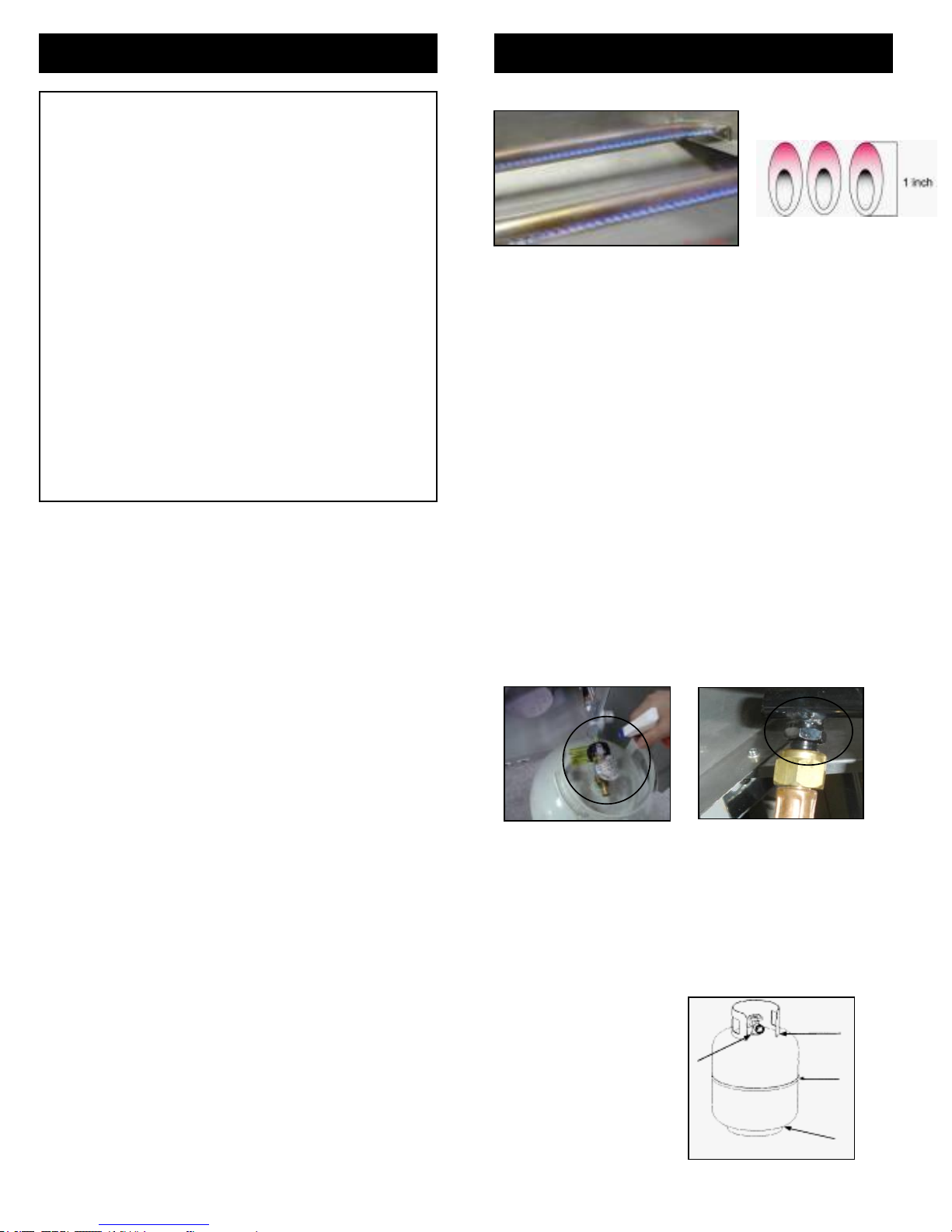
Visually check the burner flames prior to each use. The flames should
look like picture, if they do not, refer to the cleaning burner tubes and
ports, see page 30 of this manual.
CAUTION: Beware of Flash-Back Burner Flame Check
1. Make a 50/50 (soap/water) mild soap solution.
2. Turn the control knobs to full OFF position; then turn gas ON at
supply tank.
3. Apply the soap solution with a clean brush to all gas connections.
See below. If growing bubbles appear in the solution the
connections are not properly sealed. Check each fitting and
tighten or repair as necessary.
4. If you have a gas connection leak you cannot repair, turn gas
OFF at supply tank, disconnect fuel line from your grill and call
1-800-913-8999 or your gas supplier for repair assistance.
5. Also apply soapy solution to the tank seams. See below. If
growing bubbles appear, shut tank OFF and do not use or move
it! Contact an LP gas supplier or your fire department for
assistance.
Gas Connection Leak Check
Gas Tank Leak Check
Checking for LP gas leaks
Never test for leaks with a flame. Prior to first use, at the beginning
of each season, or every time your LP gas tank is changed, you
must check for gas leaks.
5
WARNING
Failure to open grill lid during the lighting
procedure could result in a fire or explosion that
could cause serious bodily injury, death, or
property damage.
!
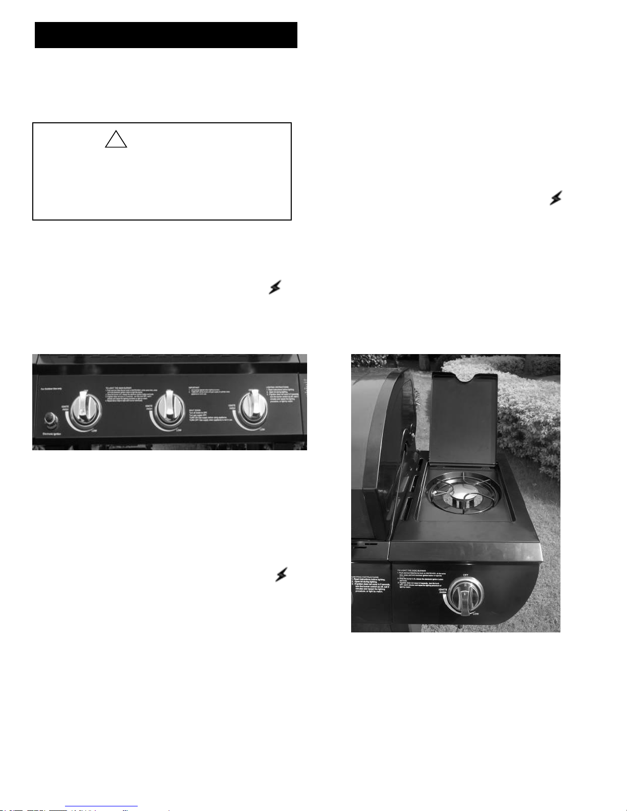
USING THE SIDE BURNER:
Inspect the gas supply hose prior to turning the gas
“ON”. If there is evidence of cuts, wear or abrasion, it
must be replaced prior to use. Do not use the side
burner if the odor of gas is present. WARNING: Always
keep your face and body as far away from the
burner as possible when lighting.
Grill Lighting Instruction
LIGHTING INSTRUCTIONS FOR SIDE BURNER
1. Make sure the lid is open.
2. Push and slowly turn the Side Burner knob to /HIGH at
the same time, press and hold electronic ignition button to
light the burner. Once the burner is lit, release the
electronic ignition button and knob.
3. If burner does not light within 5 seconds, turn the knob to
OFF position and repeat the lighting procedure.
4. If burner fails to light after step 3, turn the knob to OFF
position, wait 5 minutes, then repeat the lighting procedure
or light by match.
3. Be sure all gas connections are securely tightened.
4. Turn on gas supply.
5. Open the grill main lid.
6. Push and turn any main burner control knob to
/HIGH, at the same time, press and hold electronic
ignition button to light the burner. Once the burner is lit,
release the electronic ignition button and knob.
7. If the burner does not light after 5 seconds, turn knob
to OFF. Turn gas OFF at LP tank and wait 5 minutes
for gas to clear. Then turn gas ON at tank and repeat
step 6.
8. If burner still does not light, see Match Lighting section
and If Grill Still Fails to Light section on following page.
9. To light additional burners, turn burner knob(s) to
/HIGH . Push and hold electronic ignition button to
light burner. Adjust knob(s) to desired setting.
Grill Lighting Instructions for Main Burners
1. Do not smoke while lighting grill or checking gas supply
connections.
2. Be sure that LP gas tank is sufficiently full.
6
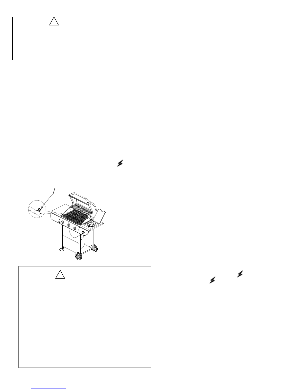
WARNING
Never lean over the grill cooking area while lighting
your gas grill. Keep your face and body a safe
distance (at least 18 inches) from the cooking grid
surface when lighting your grill by match.
If Grill Still Fails To Light
1. Check gas supply and connections for leaks. Check that
all wire connections are secure.
2. Repeat basic lighting procedure. If your grill still fails to
operate, turn the gas off at source, turn the control knobs to
OFF, then check the following:
• Misalignment of burner tubes over orifices
Correction: Reposition burner tubes over orifices.
• Plugged orifice
Correction: Remove burners from grill, carefully lift each
burner up and away from gas valve orifice. Remove the
orifice from gas valve and gently clear any obstruction with
a fine wire. Then reinstall all orifices, burners, and cooking
components.
3. If an obstruction is suspected in grill burner valves,
please call for repair service at 1-800-913-8999.
4. If the grill still does not light you may need to purge air
from the gas line or reset the pressure regulator excess gas
flow device. Note: This procedure should be done every
time a new LP gas tank is connected to your grill.
To purge air from your gas line and/or reset the
pressure regulator excess gas flow device:
• Turn all control knobs to the OFF position.
• Turn off the gas at the tank valve.
• Disconnect pressure regulator from LP gas tank.
• Let unit stand for 5 minutes.
• Reconnect pressure regulator to the LP gas tank.
• Turn the tank valve on slowly until ¼ to ½ open.
• Open the grill lid.
• Push and turn any control knob to .
• Turn control knobs to until all the burners are lit
• You may start to use the grill
5. If all checks or corrections have been made and you still
have questions about operating your gas grill, call the Grill
Information Center at 1-800-913-8999
WARNING
Should a “FLASH-BACK” fire occur in/or around the
burner tubes, follow the instructions below. Failure
to comply with these instructions could result in a
fire or explosion that could cause serious bodily
injury, death, or property damage.
• Shut off gas supply to the gas grill.
• Turn the control knobs to OFF position.
• Put out any flame with a proper fire extinguisher.
• Open grill lid.
• Once the grill has cooled down, clean the burner tubes
and burners according to the cleaning instructions found
on page 30.
!
!
•If the burner will not light after several attempts then the burner
can be match lit, before using the match allow 5 minutes for any
accumulated gas to dissipate.
•Clip a paper match on one end of the lighting rod.
•Light match.
•Hold lighting rod and insert lighted match right next to the
burner ports or ceramic file.
•Push and turn the designated control knob to /HIGH.
•Burner should ignite immediately.
Match light
7
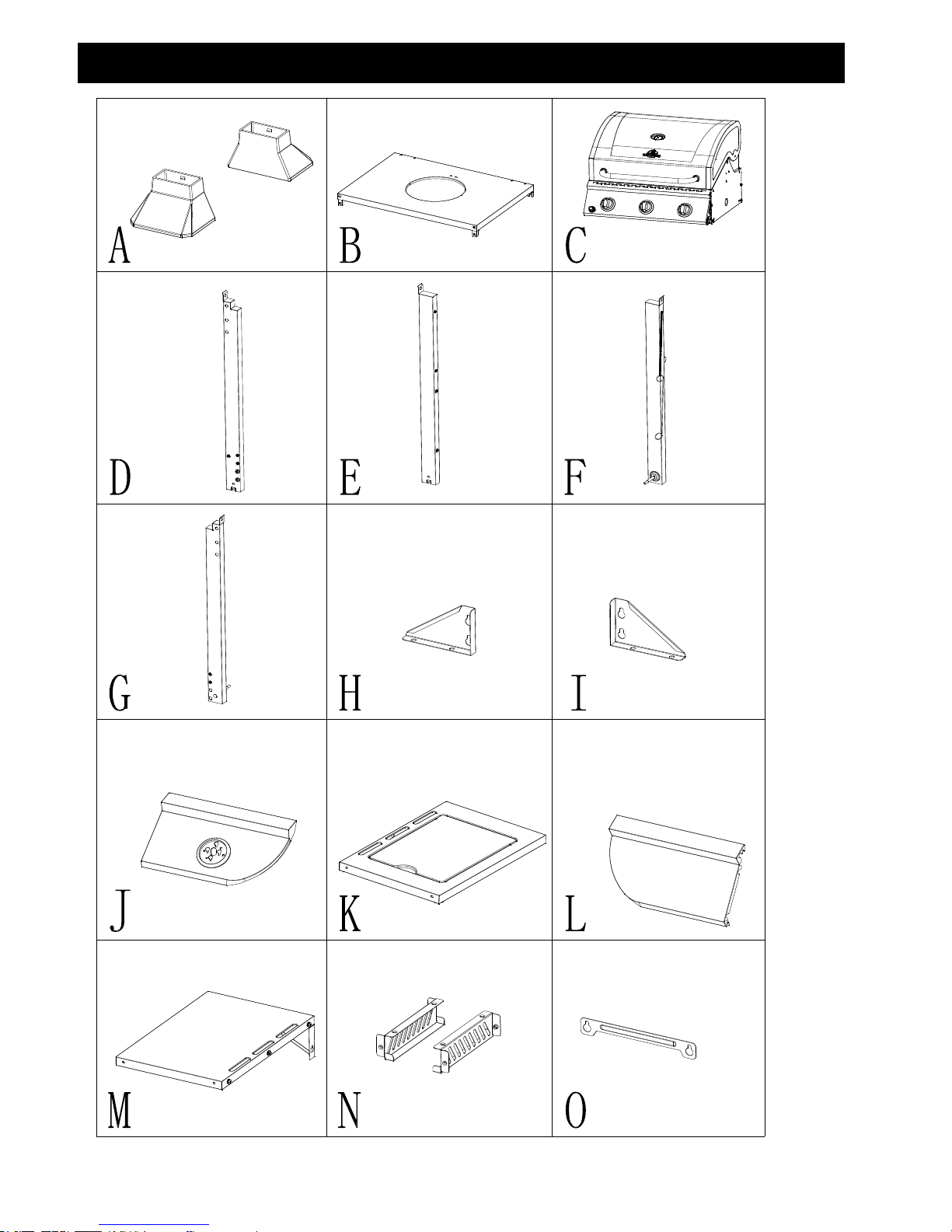
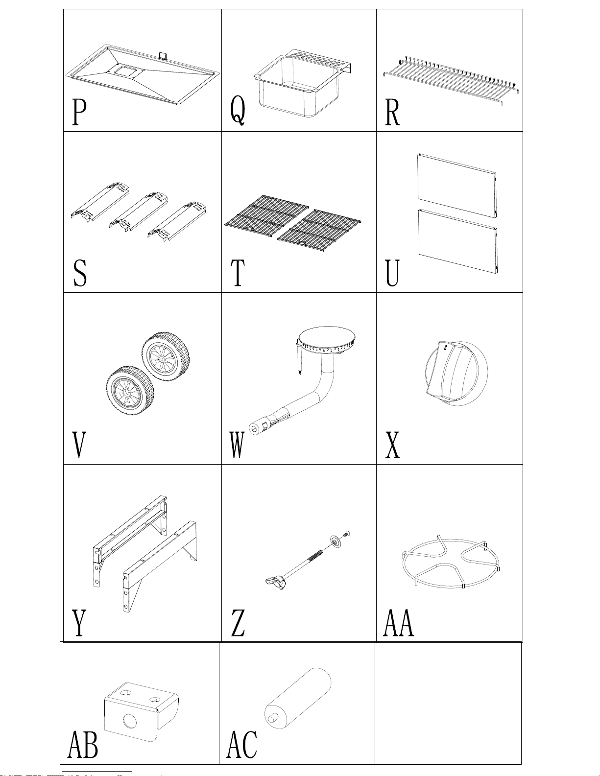
Cart Caster insert2PCS
Bottom Panel-1pc
Firebox
Assembly-1pc
Cart Leg,
Front
Left-1pc.
Cart Leg, Back
Left-1pc.
Cart Leg,
Front
Right-1pc.
Cart Leg,
Back Right-
1pc.
Triangle Bracket, Right1pc.
Triangle Bracket, Left1pc
Side Burner Shelf Control
Panel-1pc.
Side Burner Shelf-1PC Left Side Control Panel-
1pc.
Left Side Shelf -1pc.
Grease Cup Bracket-2pcs
Grease Cup Baffle-
1pc
Package Parts List
8
9
Grease Tray-1pc
Grease cup-1pc
Warming rack-1pc
Flame Tamer-3pcs
Cooking Grid-2pcs
Front Panel-2pcs
Wheel-2pcs
Side Tube Buner-1pc Side Burner Control
Knob-1pc
Cart Frame, Top-2pcs
Tank Bolt-1pc
Side burner cooking
grod-1 piece
Bottom panel bracket-1pc Battery-1pc
Before beginning assembly, make sure all parts are present. Compare parts with package contents list and diagram
above. If any part is missing or damaged, do not attempt to assemble the product. Contact Grill Information Center at
1-800-913-8999 or replacement of missing parts.
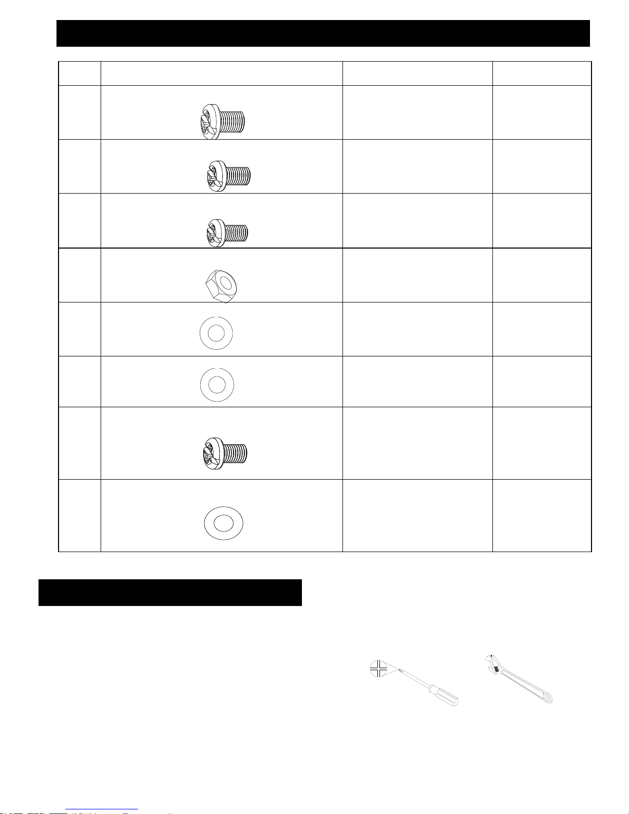
•Tools required for Assembly.
Phillips Screwdriver (not included) and Wrench (not included)·
• Note: The left and right sides of the grill are on your left and right as you face the front of the grill.
Phillips Screwdriver Wrench
Preparation
Hardware Pack Contents
10
Item Description Specification Quantity
Screw
Screw
Screw
Nut
Flat Washer
HH
Flat Washer
1/4"
6pcs
AA
FF
Flat Washer
M4
4pcs
GG
screw
5/32'' x 8mm, black
6pcs
1/4'' x 12mm, black
5/32'' x 10mm, black
2pcs
5/16"
6pcs
32pcs
8pcs
BB
5/32'' x 10mm, 430 SS
CC
EE
5/16"
2pcs
DD
W1/ 4"x12mm螺钉
24
5/ 32"x10mm螺钉
2
W1/ 4"x12mm螺钉
黑色达可罗
24
16
5/ 32"x10mm螺钉
黑色达可罗
W1/ 4"x12mm螺钉
黑色达可罗
24
16
5/ 32"x10mm螺钉
5/ 32" x10mm螺钉
SUS430
2
5/ 16" 螺母
2
W1/ 4"x12mm螺钉
黑色达可罗
24
16
5/ 32"x10mm螺钉
黑色达可罗
5/ 32"x10mm螺钉
SUS430
2
5/ 16" 螺母
2
W1/ 4"x12mm螺钉
黑色达可罗
5/ 16" 垫片
24
2
16
5/ 32"x10mm螺钉
黑色达可罗
W1/ 4"x12mm螺钉
黑色达可罗
5/ 16" 垫片
32
2
8
5/ 32"x10mm螺钉
黑色达可罗
5/ 32"x10mm螺钉
镀白锌
6
5/ 16"螺母
2
M4 垫片镀白锌
4
6
5/ 32"x8mm螺钉
W1/4"x12mm螺钉
黑色达可罗
5/ 16" 垫片
32
2
8
5/ 32" x10mm螺钉
黑色达可罗
5/ 32" x10mm螺钉
镀白锌
6
5/ 16" 螺母
2
M4 垫片镀白锌
4
5/ 32"x10mm螺钉
SUS430
2
5/ 16" 螺母
2
W1/4"x12mm螺钉
黑色达可罗
5/ 16" 垫片
24
2
16
5/ 32"x10mm螺钉
黑色达可罗
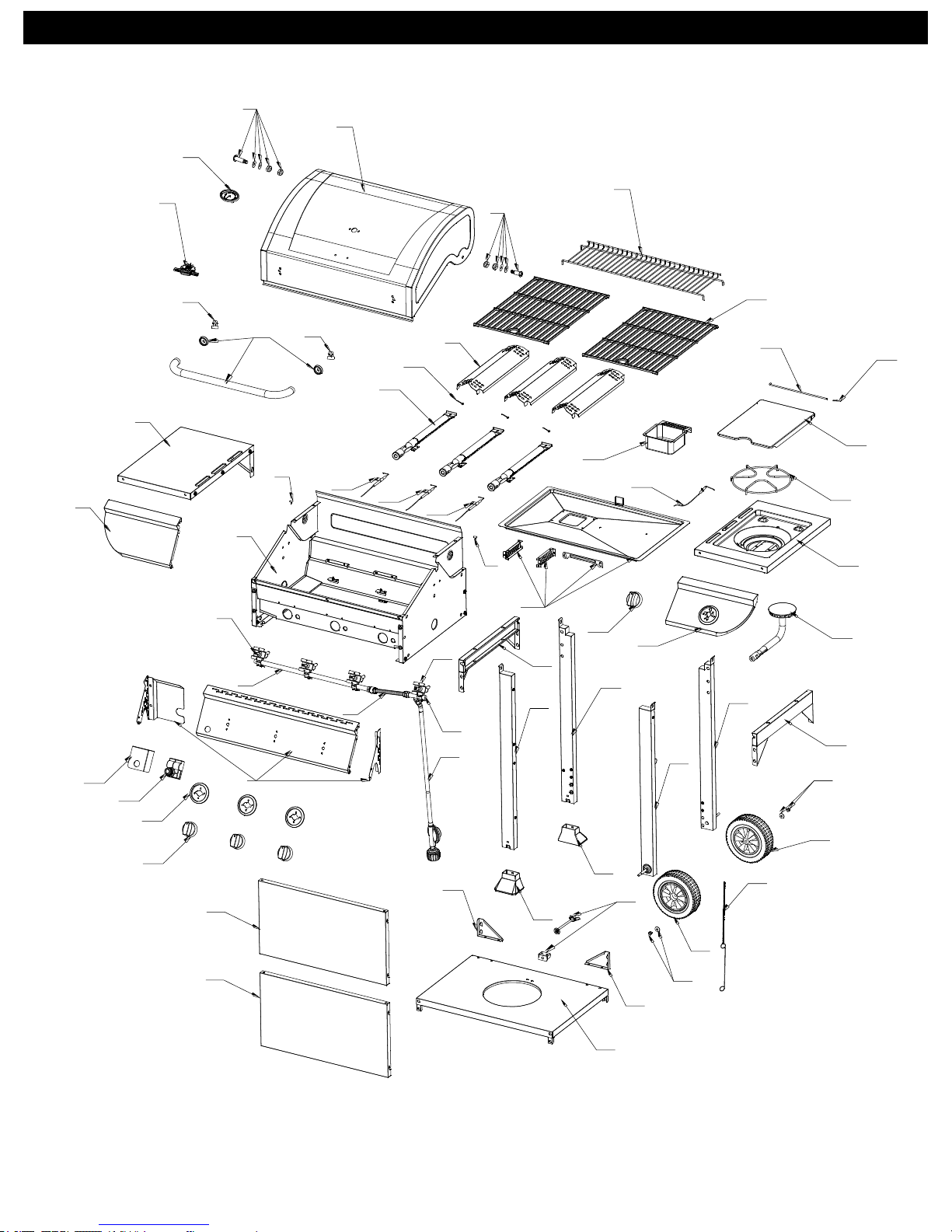
Exploded View
11
53
1
4
3
2
5
2
9
10
11
12
13
15
16
14
37
17
17
7
8
36
35
30
31
32
33
34
39
38
29
40
41
42
44
43
45
47
48
47
45
49
49
50
51
52
29
28
26
27
25
18
19
20
21
23
22
24
40
46
53
5
6
Parts List
12
No. Part No. PART (Description) Warranty Qty No. Part No. PART (Description) Warranty
Qt
y
01 0894A-001 Main Lid 1 1 28 0894A-028 Bezel
1
3
02 0894A-002 Main Lid Screw 1 2 29 0894A-029 Control Knob
1
4
03 0894A-003 Temperature Gauge 1 1 30 0894A-030 Side Burner Lid Hinge Rod
1
1
04 0894A-005 Logo 1 1 31 0894A-031
Side Burner Lid Hinge Rod
Pin
1
1
05 0894A-006 Hood Buffer A 1 2 32 0894A-032 Side Burner Lid
1
1
06 0894A-006 Main Lid Handle 1 1 33 0894A-033 Side Burner Cooking Grid
1
1
07 0894A-007 Side Shelf 1 1 34 0894A-034 Side Burner Bowl Assembly 1 1
08 0894A-008 Side Shelf control panel 1 1 35 0894A-035 Side Burner Igniter Wire
1
1
09 0894A-009 Warming Rack 1 1 36 0894A-036 Grease cup 1 1
10 0894A-010 Cooking Grid w/Hole 1 2 37 0894A-037 Grease Tray Assembly
1
1
11 0894A-011 Flame Tamer 1 3 38 0894A-038 Side Burner Control Panel
1
1
12 0894A-012 R pin A 1 3 39 0894A-039 Side Burner Pipe
1 1
13 0894A-013 Main Burner 1 3 40 0894A-040 Cart Frame 1 2
14 0894A-014 Main Burner Igniter Wire A 1 1 41 0894A-041 Cart Leg Rear, Left
1 1
15 0894A-015 Main Burner Igniter Wire B 1 1 42 0894A-042 Cart Leg Front, Left
1 1
16 0894A-016
Main Burner Igniter Wire
C
1
1 43 0894A-043 Cart Leg Rear, Right
1 1
17 0894A-017 Hood Buffer B
1
2 44 0894A-044 Cart Leg Front, Right
1 1
18 0894A-018
Main Burner Bowl
Assembly
Non-
replaceable
1
45 0894A-045 Wheel Screw Assembly
1 2
19 0894A-019 Main Gas Valve
1
3 46
0894A-046 Bottom Panel, LP
1 1
20 0894A-020 Main Manifold
1
1 47 0894A-047 Wheel
1 2
21 0894A-021 Side Burner Flex Gas Line
1
1 48 0894A-048 Lighting Rod
1 1
22 0894A-022 Side Burner Gas Valve
1
1 49 0894A-049 Cart Caster Insert
1 2
23 0894A-023 Side Manifold
1
1 50 0894A-050 Tank Bolt
1 1
24 0894A-024 Regulator, LP
1
1 51 0894A-051 Triangle Bracket, Right
1 1
25 0894A-025 Control panel
1
1 52 0894A-052 Triangle Bracket, Left
1 1
26 0894A-026 Igniter module heat shield
1
1 53 0894A-053 Front Panel
1 2
27 0894A-027 Pulse Ignite Module
1
1
Assembly Instructions
If you are missing hardware or have damaged parts
after unpacking grill, call 1-800-913-8999 for
replacements.
To order replacement parts after using grill, call:
1-800-913-8999.
To make sure you obtain the correct replacement parts
for your Grillmaster gas grill, please refer to the part
numbers in the part list.
Important: Use only parts listed above. When ordering
parts, providing the following information:
1. Model #
2. Serial # (found inside the front panel of your grill)
3. Part Number (see PART# in chart)
4. Part Description
5. Quantity of parts needed
13
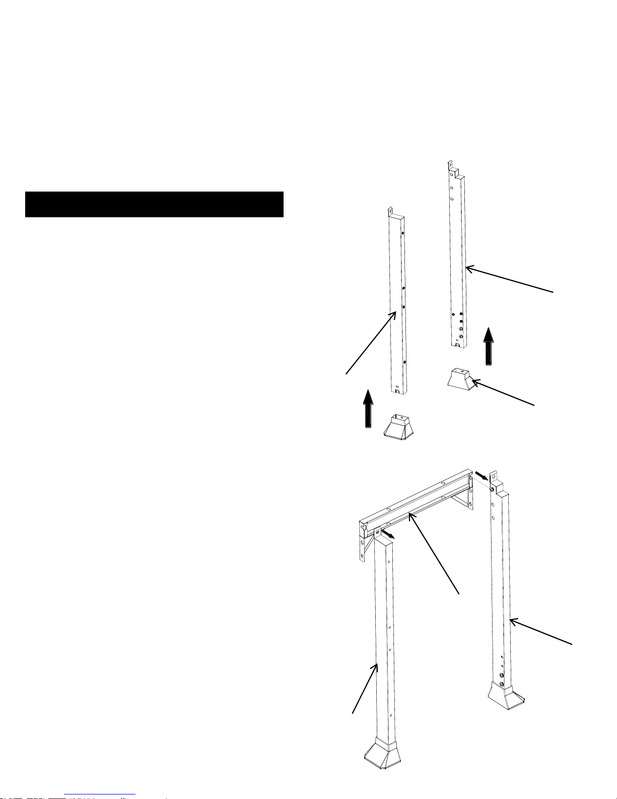
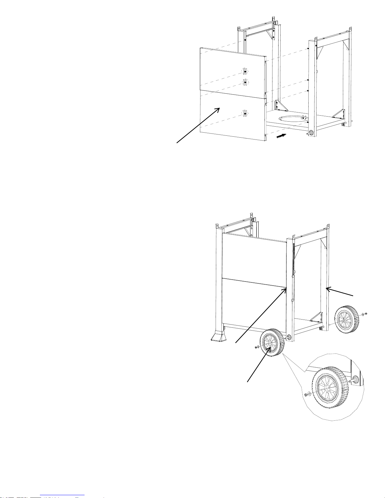
1. Cart Caster and Cart Assembly
a) Cart Caster Insert (A) into the Cart Leg, Front Left (D)
and Cart Leg, Back Left (E). As shown in Fig. 1.
b) Loosen, but do not remove the screws that are pre-
assembled on the Cart Leg, Back Left (D) and Cart Leg,
Front Left (E). Attach Cart Leg, Back Left (D) and Cart Leg,
Front Left (E) to Cart Frame (Y), by aligning the holes on
the Cart Frame (Y). Tighten the screws that were loosened
above. As shown in Fig. 2.
A
D
E
D
Y
E
Fig. 1.
Fig. 2.
14
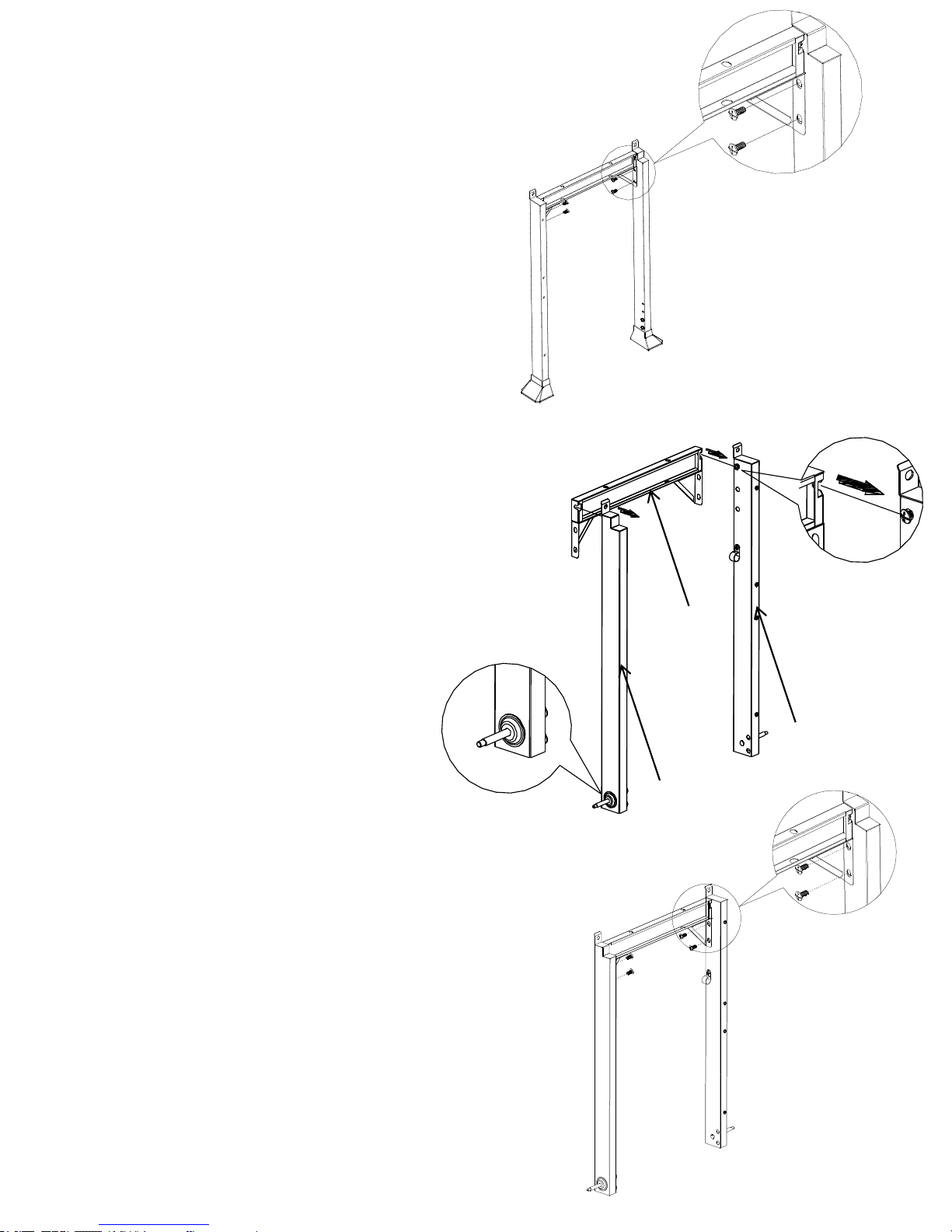
c) Attach the front and rear cart beam triangle bracket
by using four 1/4"x12mm black screws (AA) which in
the hardware pack. As shown in Fig. 3.
d) Loosen, but do not remove the screws that are pre-
assembled on the Cart Leg, Front Right (F )and Cart
Leg, Back Right (G). Attach Cart Leg, Front Right (F)
and Cart Leg, Back Right (G) to Cart Frame (Y), by
aligning the holes on the Cart Frame. Tighten the
screws that were loosened above. As shown in Fig.
4.
e) Attach the front and rear cart beam triangle bracket by
using four 1/4"x12mm black screws (AA) which in the
hardware pack. As shown in Fig. 5.
Y
F
G
Fig. 3.
Fig. 4.
Fig. 5.
15
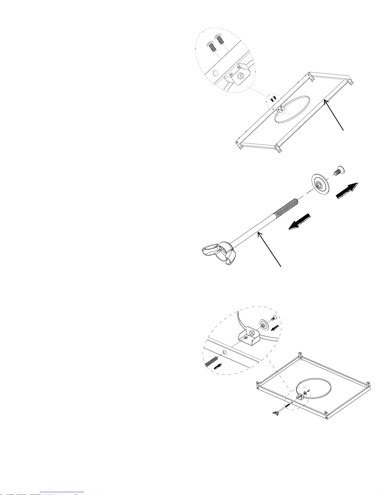
2. Bottom Panel Assembly
a) Attach the tank bolt bracket under the bottom Panel (B)
by using two 1/4"x12mm black screws (AA) which in
the hardware pack. As shown in Fig. 6.
b) Loose the flat washer and screw from
tank bolt (Z). As show in Fig. 7.
c) Then screw in the bottom panel bracket. As show in Fig.8.
B
Fig. 8.
Fig. 7.
Fig. 6.
Z
16
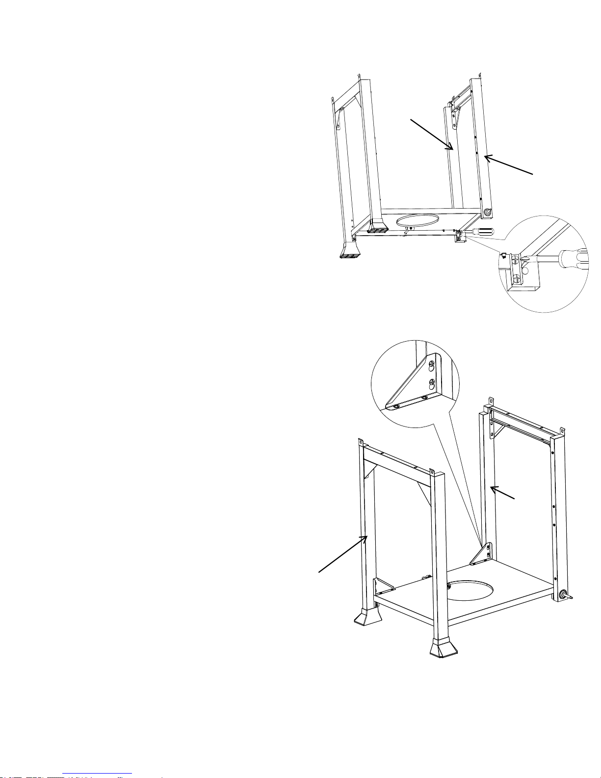
d) Place upside down the bottom panel and attach to the Cart Leg,
Back right (G) and cart leg, Front right (F) by using four 1/4"x12mm
black screw (AA) which are in the hardware pack. As show in Fig. 9.
e) Repeat step d to attach left legs to the bottom
panel making sure all screws are tight.
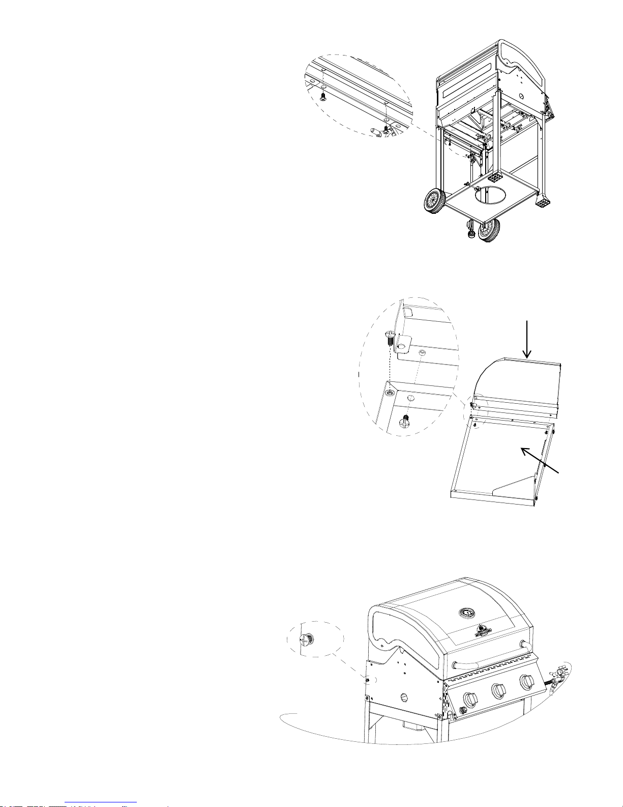
3. Triangle Bracket Assembly
a) Loosen, but do not remove four screws pre-assembled on
Cart Leg, Back Left (D) and Cart Leg, Back Right (G).
Align the holes of the triangle brackets with the screws in
the Cart Leg, Back Left (D) and Cart Leg, Back Right
(G) .Then tighten the screws.
b) Attach the triangle brackets to bottom panel (B) by using
four 5/32"x10mm black screws (BB). As show in Fig.10.
Note: The flat portion of the triangle should face
the rear of the grill.
Fig. 10.
Fig. 9.
G
F
G
D
17
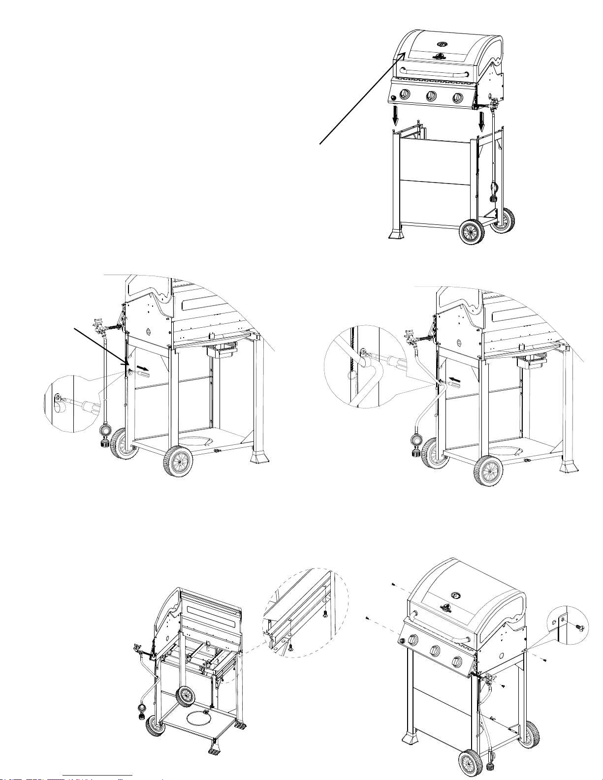
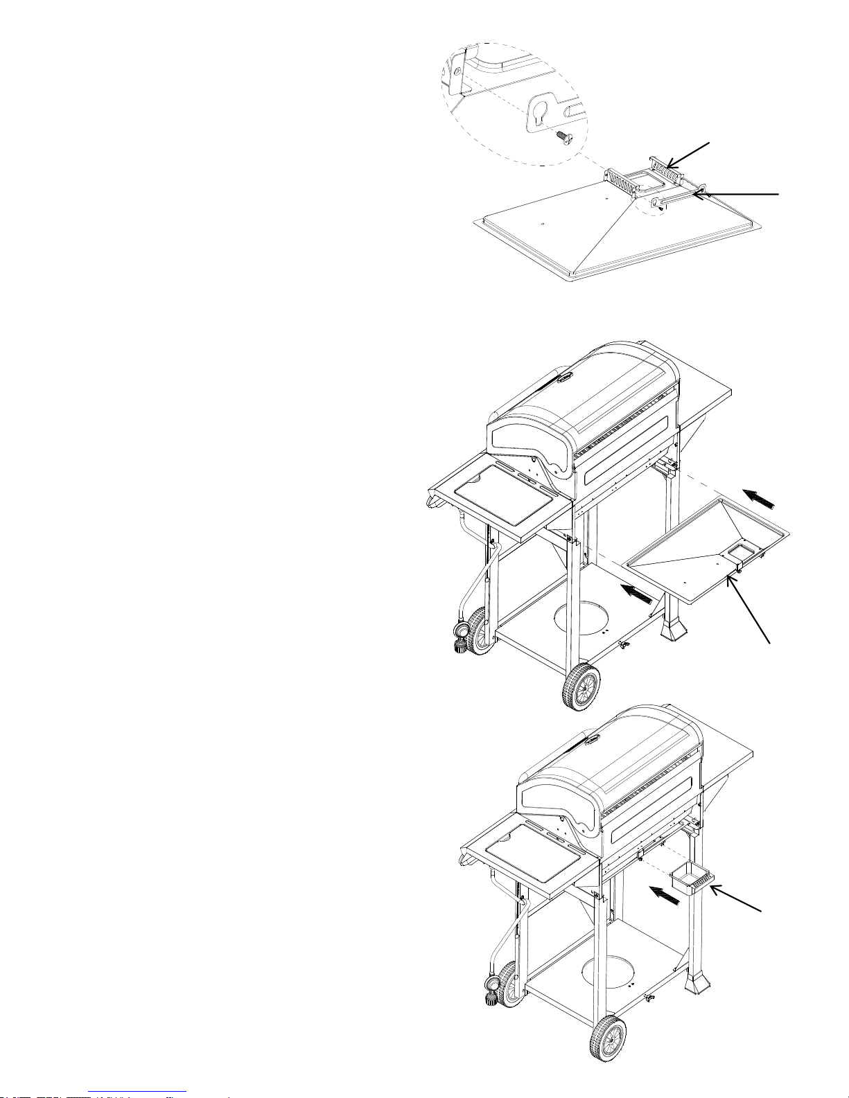
4. Front Panel Assembly
a) Loosen, but do not remove the screws which are
pre-assembled on the cart legs, align the holes on
the front panel (U) with the screw in the legs, then
place the front panel (U) onto the screws in the cart
legs. As shown in Fig. 11.
b) Tighten the screws that were loosened in step 4a.
Note: Flat side of the front panel (U) should face out.
5. Wheel Assembly
a) Place the wheels (V) on the axle which stable in the Cart Leg,
Front Right (F) and Cart Leg, Back Right (G)
b) Place two 5/16“ nuts (DD) and two 5/16” flat washers (EE)
which in the hardware pack to the axle and tighten the nuts.
As shown in Fig. 12.
U
V
F
G
Fig. 12.
Fig. 11.
18
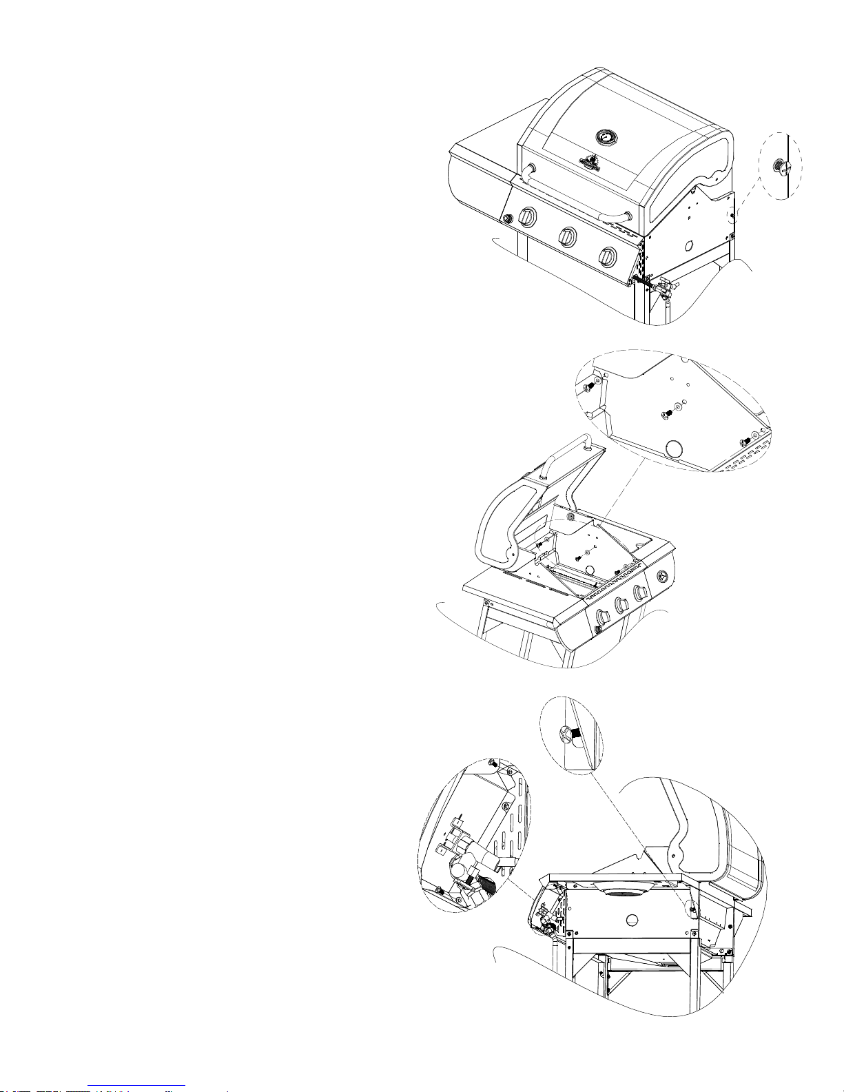
6. Firebox Assembly
NOTE: We suggest two persons lift the firebox when
assembling. Be sure to remove all packaging
material during assembly.
a) Remove the Firebox Assembly (C) from the
carton and carefully place onto the grill cart .lid
handle will face front and be above front panel. As
shown in Fig. 13.
b) Secure the firebox to the four cart leg by using
four1/4"x12mm black screws (AA) which in the
hardware pack. As shown in Fig. 14.
c) Secure the firebox left to the cart beam by using two
1/4"x12mm black screws (AA) which in the hardware
pack. As shown in Fig. 15.
C
Fig. 15.
Fig. 14.
Fig. 13.
Loose the screw which is pre-assembled in the
cart leg front , right (F).
Attach the gas hose to the fixture and fix the
screw which is loosen in above step.
F
19
d) Secure the firebox right to the cart beam by
using two 1/4"x12mm black screws (AA)
which in the hardware pack. As shown in Fig.
16.
e) Attach the side shelf control panel (L)to left side shelf (M)
by using three black 5/32“x8mm screws (GG), which are
in the hardware pack.
7 . Left Side Shelf Assembly
a) Loosen but do not remove the screw which is
pre-assembled on the outside firebox, left. As
shown in Fig. 17.
Fig. 17.
Fig. 16.
L
M
20
b) Attach the side shelf to the firebox, left. Secure
from inside firebox by using three 1/4"x12mm
black screws (AA) and ¼” flat washer (HH) which
are in the hardware pack. As shown in Fig. 18.
d) Align the hole on the side shelf bracket with the loosened
screw located on the outside firebox and tighten.
e) Secure the side shelf control panel and main control panel
by using two 5/32"x10mm black screws (BB) which in the
hardware pack. As show in Fig. 19.
f) Attach the side burner control panel (J) to the side
burner shelf (K) by using three 5/32"x8mm black
screws (GG) which are in the hardware pack.
Fig. 19.
Fig. 18.
J
K
21
8. Side Burner Shelf Assembly
a) Loosen but do not remove the
screw which is pre-assembled on
the outside firebox, right. As
shown in Fig. 20.
b) Attach the side burner shelf to the firebox, right. Secure
from inside of the firebox by using three 1/4"x12mm black
screws (AA) and ¼” flat washer (HH) which are in the
hardware pack. As shown in Fig. 21.
c) Align the hole on the side burner shelf
bracket with the loosened screw located on
the outside firebox and tighten. As shown in
Fig. 22.
Fig. 22.
Fig. 21.
Fig. 20.
d) Secure the side burner control panel and main control
panel by using two 5/32"x10mm black screws(BB) which
are in the hardware pack. As show in Fig. 22
22
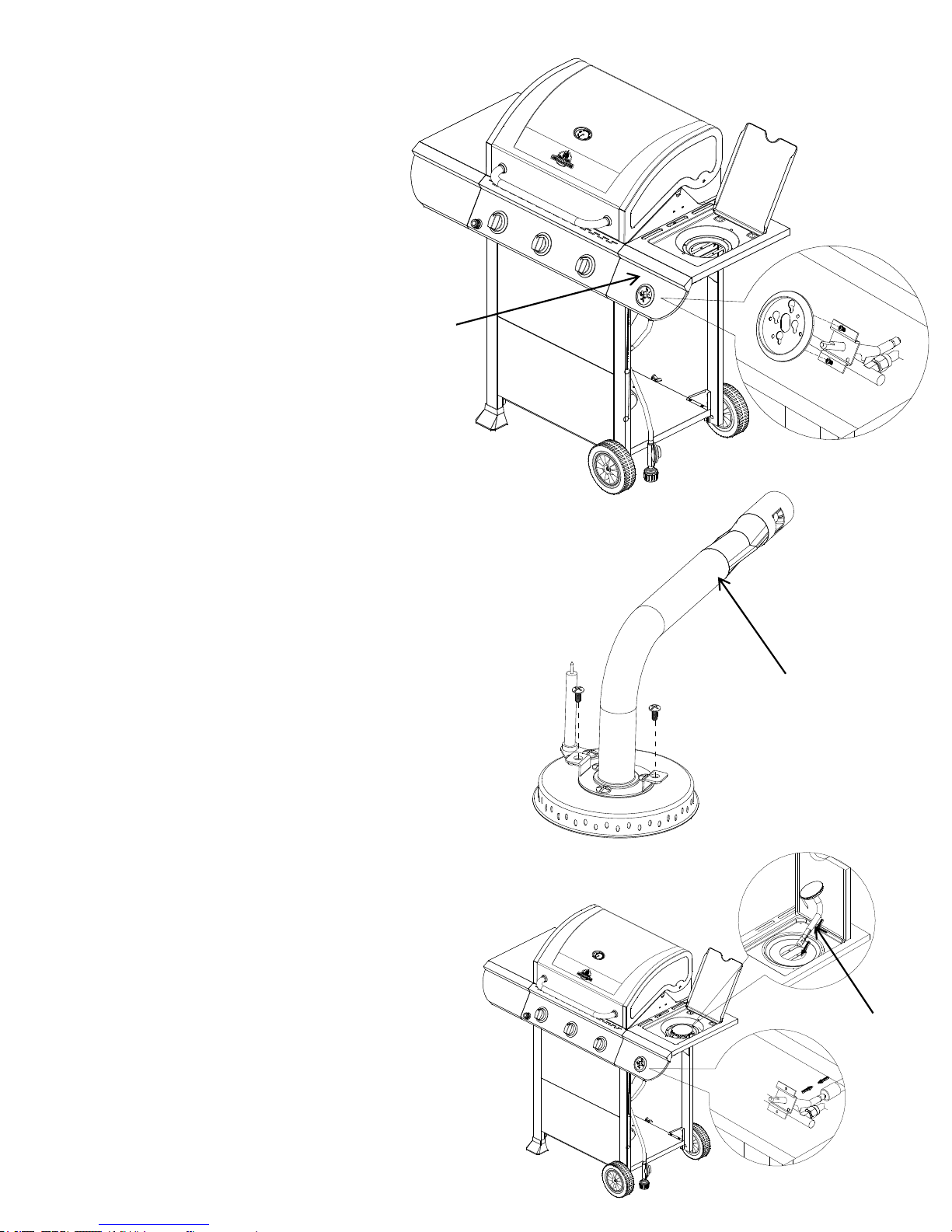
9. Side Burner Valve Installation
a) Insert the side burner valve into the Side
Burner Shelf Control Panel (J). Align the
screws on the valve with the large side of the
holes on the bezel. Slightly loosen the screws
without removing the screws. Slide the screws
down to the smaller holes and tighten the
screws to secure. As shown in Fig. 23.
10. Side Burner Installation
a) From underneath the side burner remove two screws which
are assembled on the bottom of the side tube burner (W).
As shown in Fig. 24.
b) Open side burner lid and place the Side Tube Burner
(W) through the opening. Place the Side Tube Burner
(W) tube over the side burner gas valve and make sure
Side Burner gas valve is inserted into side burner tube.
As shown in Fig. 25.
J
W
Fig. 25.
Fig. 24.
Fig. 23.
W

23
c) Then with two screws removed in step 10a, secure
the side burner from underneath to the Side Burner
Shelf (D). As shown in Fig. 26.
d) Connect ignition wire from Firebox Assembly (C)
control panel to the side burner igniter pin from
underneath the Side Burner Shelf & Control Panel
(J). As shown in Fig. 26.
e) Put the side burner control knob back on. As
shown in Fig.26.
Note: After completing side burner installation,
make sure here has no more than a 3 mm gap
between igniter pin and burner. As shown in Fig. 27.
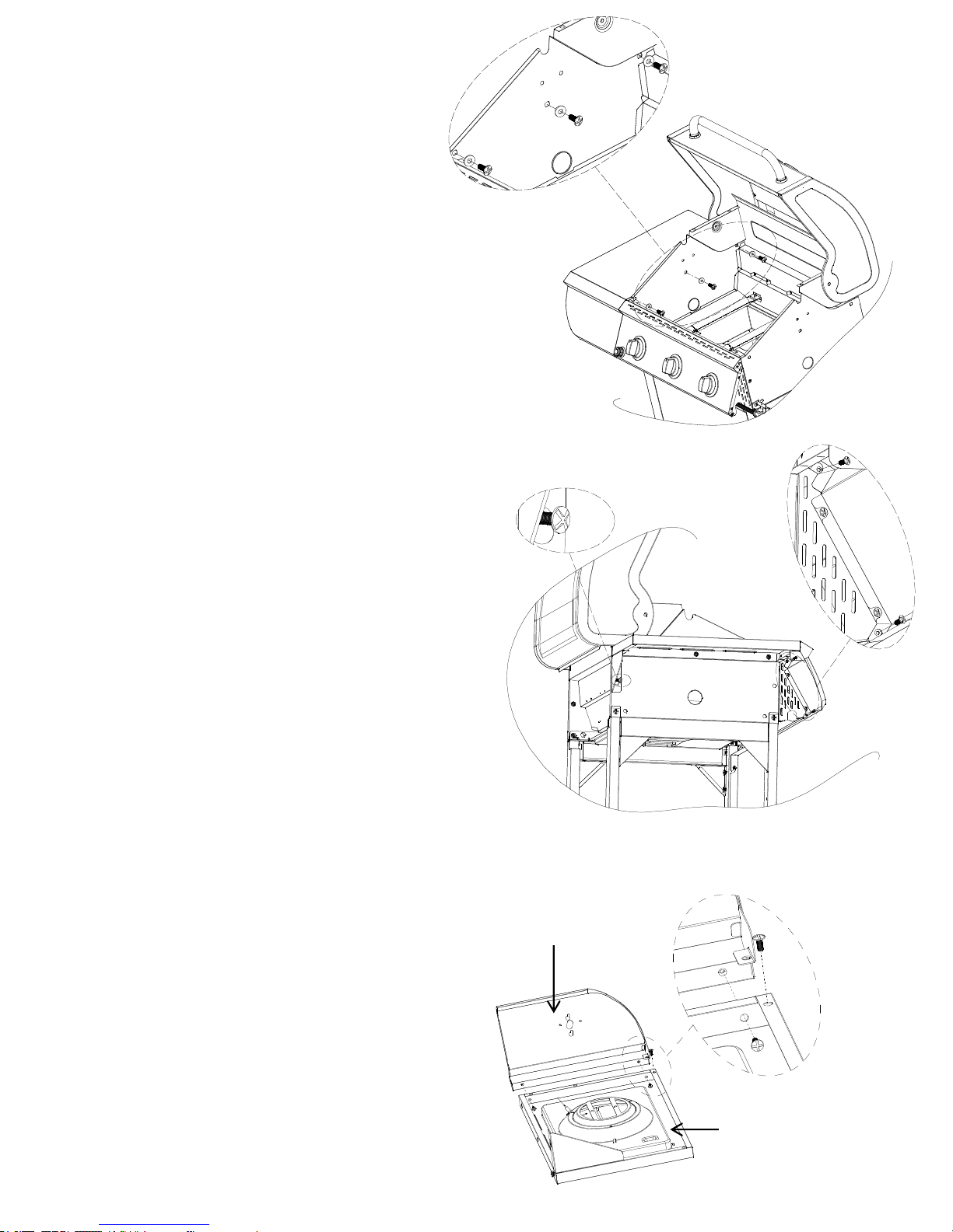
11. Install the Grease Tray
a) Attach the grease cup bracket (N) to the grease
tray (P) by using four 5/32"x10mm 430SS (CC)
and four M4 flat washer (FF) which are in the
hardware pack. As shown in Fig. 28.
J
C
Fig. 28.
Fig. 27.
Fig. 26.
Side burner
lgniter wire
Side burner
3.2mm~3.5mm
N
P
24
b) Attach the grease cup baffle (O) to the grease cup
bracket (N) by using two 5/32"x10mm 430SS
(CC) which are in the hardware pack. As shown in
Fig. 28.
c) Install the Grease Tray (P) from the rear of the
grill by sliding the tray on the glides at the rear
of the grill until centered under the cooking area.
As shown in Fig. 29.
d) Install Grease box (Q) under the grease tray.
P
Fig. 29.
Fig. 28.
Q
N
O
25
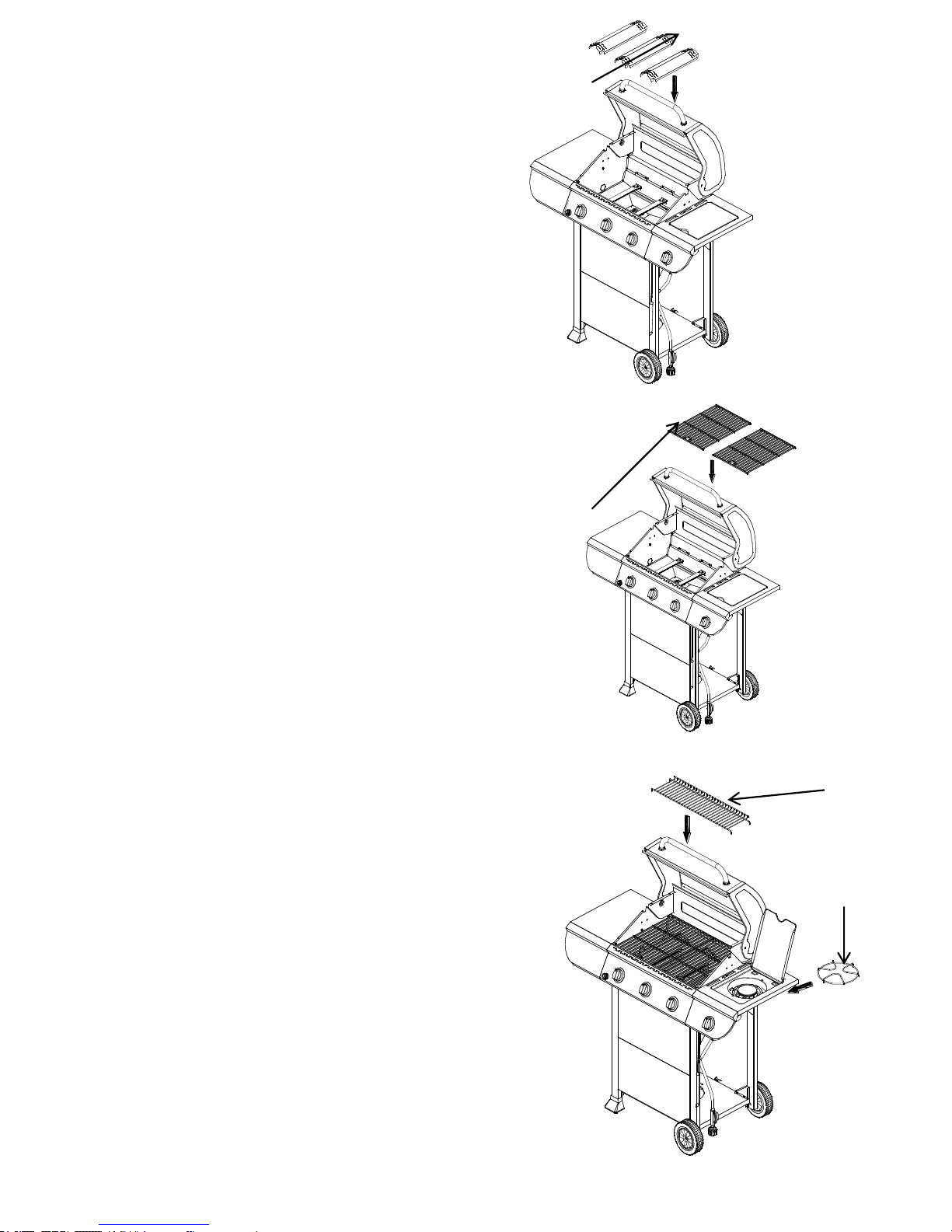
12. Position Flame Tamers and Cooking Grids
a) Place the flame tamer (S) in the firebox. Make
sure the flame tamer in within the flame tamer
bracket. As shown in Fig. 30.
b) Place the Cooking Grids (T) in the firebox. As shown
in Fig. 31.
c) Place the Warming Rack (R) on brackets. As shown in Fig. 32.
d) Place the Side Burner Cooking Grid (AA) in the side burner bowl
assembly. As shown in Fig. 32.
S
T
Fig. 32.
Fig. 31.
Fig. 30.
R
AA
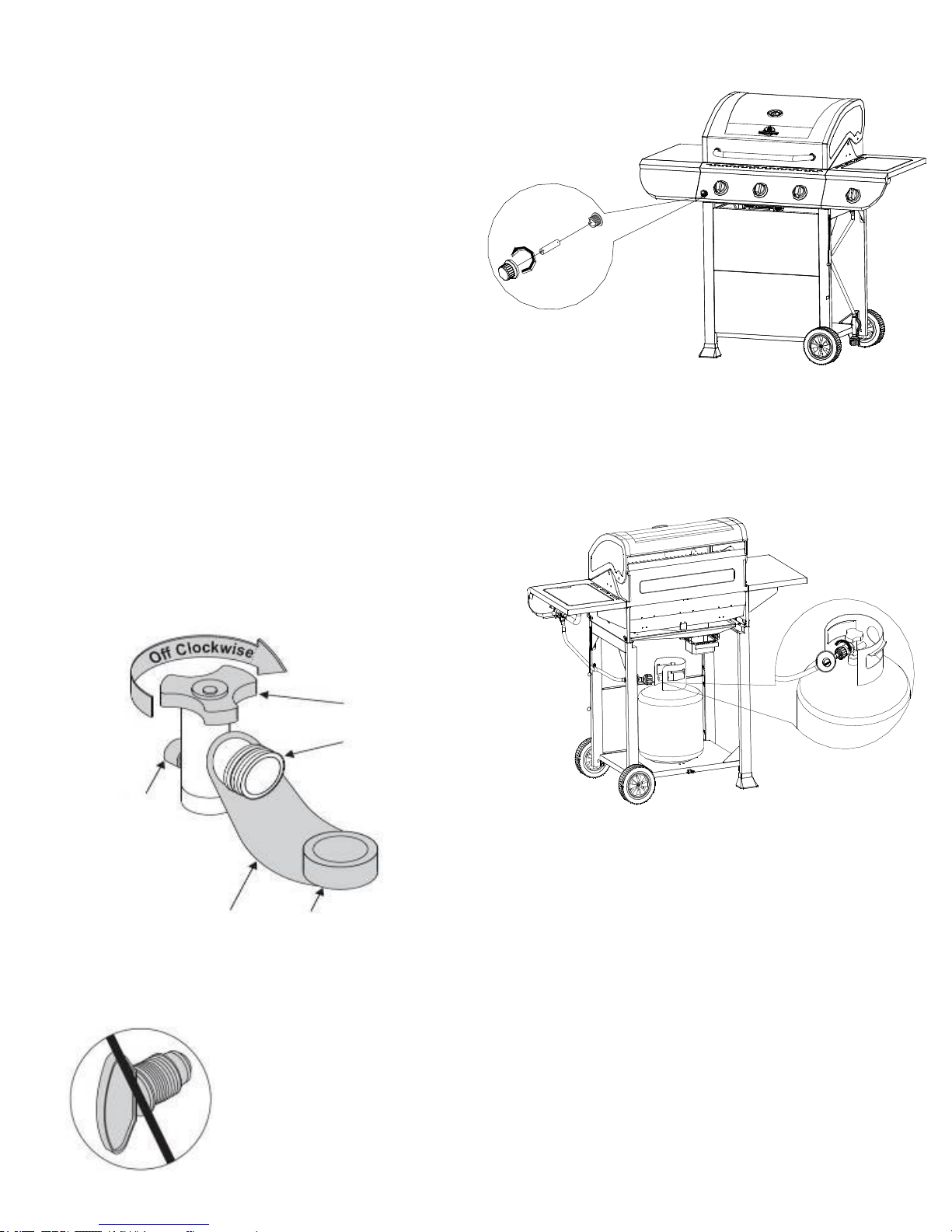
13. Battery and Liquid Propane Tank Installation
Unscrew the electronic ignition button and place the battery
into the compartment with the positive terminal
(+) facing outward. Replace the ignition button after the
battery has been installed.
From the front of cart, place LP Tank into the hole in bottom
panel. Secure the tank in place by turning the wing nut bolt to
the right.
Connecting Regulator To The LP Tank
1. LP tank must be properly secured onto grill. (Refer to
assembly section.)
2. Turn all control knobs to the OFF position.
3. Turn LP tank OFF by turning OPD hand wheel clockwise to a
full stop.
4. Remove the protective cap from LP tank valve. Always use
cap and strap supplied with valve.
OPD Hand Wheel
Safety Relief
Valve
Strap and Cap
Type 1 outlet with
thread on outside
Do not insert a POL transport plug
(plastic part with external threads)
into the Type 1 tank valve outlet . It
will defeat the Safety Relief Valve
feature.
26
Congratulations
Your Grillmaster gas grill is now ready for use.
Before the first use and at the beginning of each
season (and whenever the LP gas tank has been
changed):
1. Read all safety, lighting and operating instructions.
2. Check gas valve orifices, burner tubes and burner
ports for any obstructions.
3. Perform gas leak check according to instructions
found on next page of the manual.
Important
Before cooking on your grill the first time, wash
cooking grids and cooking rack with warm , soapy
water. Rinse and dry thoroughly. Season with
cooking oil regularly. After cooking is completed, turn
grill to HIGH setting for 3 to 5 minutes to burn off
excess grease or food residue.
DISCONNECTING THE LIQUID PROPANE CYLINDER
Turn the grill burner valves “OFF” and make sure the
grill is cool.
Turn the Liquid Propane Cylinder valve “OFF” by
turning clockwise until it stops.
Detach the pressure regulator assembly from the
cylinder valve by turning the quick coupling nut
counterclockwise.
Place dust cap on cylinder valve outlet whenever the
cylinder is not in use. Only install the type of dust cap
on the cylinder valve outlet that is provided with the
cylinder valve. Other types of caps or plugs may
result in leakage of propane.
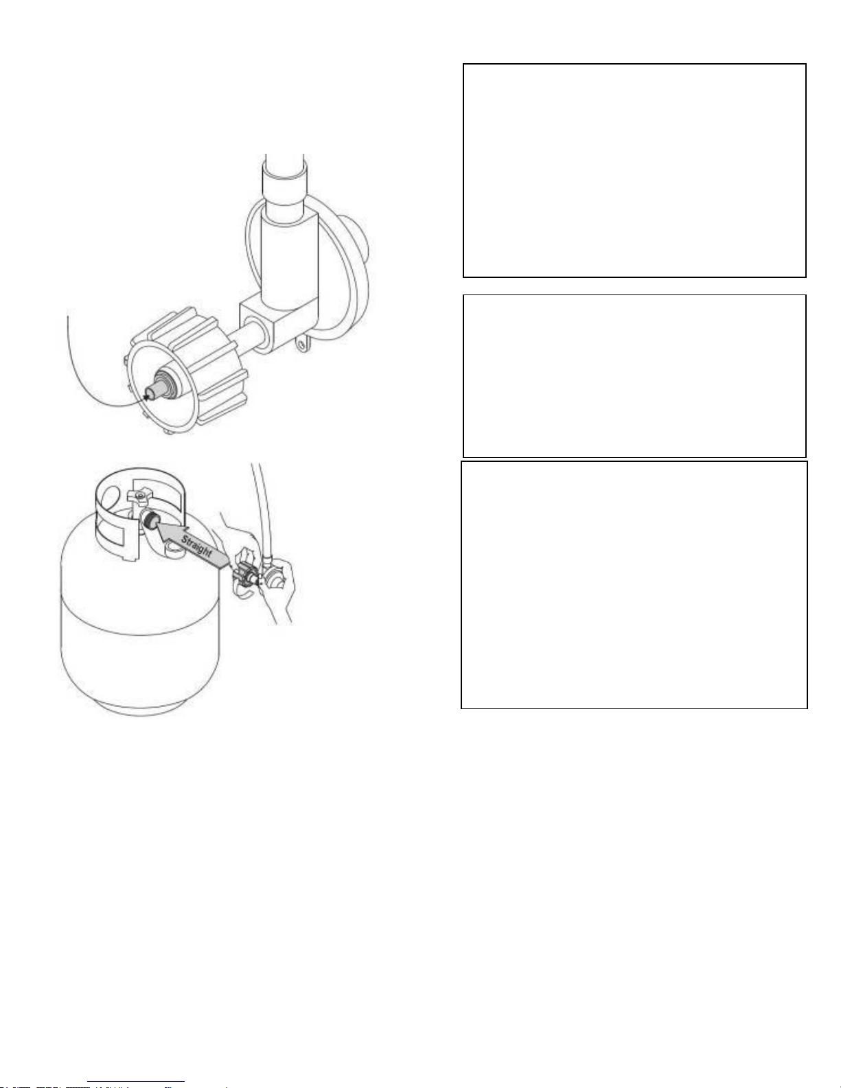
Hold coupling nut and regulator
as shown for proper connection
to LP tank valve.
Nipple has to be centered
into the LP tank valve.
5. Hold regulator and insert nipple into LP tank valve. Handtighten the coupling nut, holding regulator in a straight line with
LP tank valve so as not to crossthread the connection.
6. Turn the coupling nut clockwise and tighten to a full stop. The
regulator will seal on the back-check feature in the LP tank
valve, resulting in some resistance. An additional one-half to
three-quarters turn is required to complete the connection.
Tighten by hand only – do not use tools.
NOTE:
If you cannot complete the connection, disconnect regulator and
repeat steps 5 and 6. If you are still unable to complete the
connection, do not use this regulator! Call 1-800-913-8999 for
assistance.
27
!
WARNING
Do not leave the grill unattended.
Your grill will get very hot. Never lean over the
cooking area while using your grill. Do not touch
cooking surfaces, grill housing. Grill Lid or any other
grill parts while the grill is in operation, or until the
grill has cooled down after use. Failure to comply
with these instructions may result in serious bodily
injury.
Burn-off
Before cooking on your gas grill for the first time, you will
want to “burn off” the grill to eliminate any odor or foreign
matter. Just ignite the burners, lower the Lid, and operate
grill on the HIGH setting for 3 to 5 minutes.
Cooking Temperatures
High setting: Only use this setting for fast warm-up,
searing steaks or chops and for burning food residue off
the grill after cooking is complete. Never use the HIGH
setting for extended cooking.
Medium to Low Settings: Most recipes specify medium
to low settings, including all smoking, rotisserie cooking
and for cooking lean cuts such as fish.
NOTE: Temperature settings will vary with the
temperature and the amount of wind outside your home.
Direct Cooking
The direct cooking method can be used with the supplied
cooking grids and food placed directly over the lit grill
Burners. The method is ideal for searing and whenever
you want meat, poultry or fish to have and open-flame
barbecued taste. Deep frying and smoking are also best
cooked in this manner because they require direct heat.
Indirect Cooking
To cook indirectly, the food should be placed on the
left or right side of your grill with the burner lit on the
opposite side.
Flare-ups
The fats and juices dripping from grilled food can cause
flare-ups. Since flare-ups impart a favorably, distinctive
taste and color to food cooked cover an open flame,
they should be accepted up to a point. Nevertheless,
uncontrolled flaring can result in a ruined meal.
WARNING
Do not line the bottom of the grill housing with aluminum
foil, sand or any substance that will restrict the flow of
grease into the grease tray.
Failure to comply with these instructions could result in a
fire or explosion which could cause serious bodily injury,
death, or property damage.
!
Cooking Instructions
28
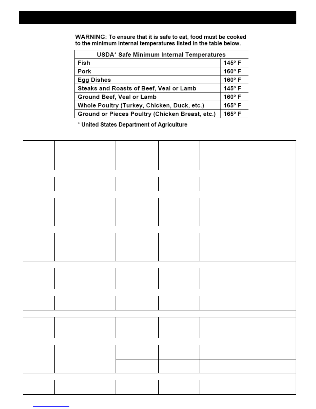
FOOD Weight or thickness Temperature Time Special instructions and tips
Vegetables NA Medium 8 to 20 minutes
Slice or chop vegetables and dot with butter or
margarine. Wrap tightly in heavy duty foil. Grill
turning occassionally.
Potatoes Whole Medium 40 to 60 minutes
Wrap individually in heavy duty foil. Cook
rotating occassionally.
Meat/Steaks 1/2 to 3/4 inches High-Medium 4 to 15 minutes
Pre heat grill for 15-20 minutes then sear
steaks on each side for two minutes. Next
grill 3 to 5 minutes on each side or until
desired doneness.
Ground Meats 1/2 to 3/4 inches Medium 8 to 15 minutes
Grill turning once when juices rise to the
surface or until desired amount of doneness.
Do not leave hamburgers unattended since a
flare-up could occur quickly.
Ribs 1/2 or full rack Medium 20 to 40 minutes
Grill turning occassionally. During last few
minutes brush with barbecue sauce, turn
several times.
Hot dogs NA Medium 5 to 10 minutes
Grill turning four times. 2-4 minutes on each of
four sides.
Poultry-Cut 1/4 to 1/2 pounds Low or Medium 20 to 40 minutes
Grill turning occassionally. During last few
minutes brush with barbecue sauce if desired,
turn several times.
Low or 1 to 1-1/2 hours
Use poultry stand and brush frequently as
desired
Medium 40 to 60 minutes
Use poultry stand and brush frequently as
desired
Fish 3/4 to 1 inch Medium 8 to 15 minutes
Grill turning once to desired doneness. Brush
with melted butter, margarine or oil.
Poultry Whole
2 to 3 pounds
Grill Cooking Chart
29
 Loading...