

Page 1
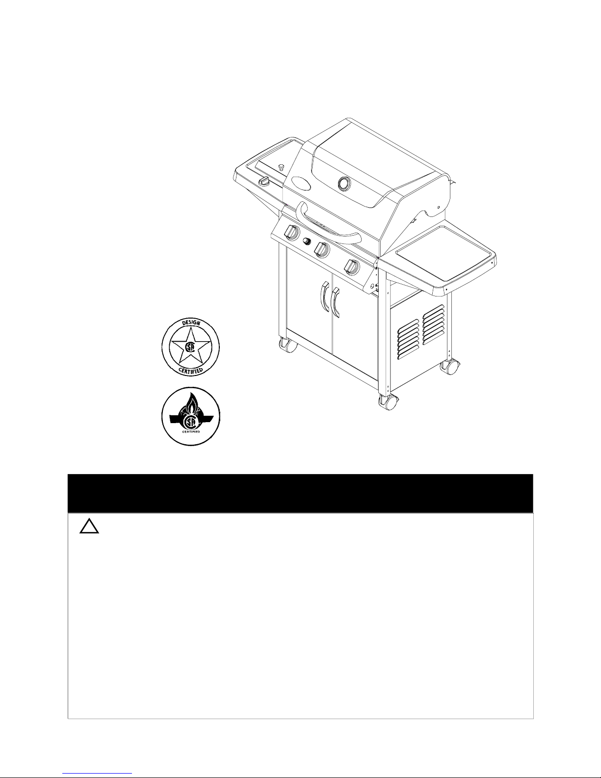
Owner's Manual
!
Liquid Propane Gas Grill
MODEL SS54 LP
MODEL SS54 LP SHOWN
Customer Service: If you have questions about assembly or grill operation, or if there are damaged
or missing parts when you unpack this unit from the shipping boxes, call us 8:00am - 5:00 pm EST,
Monday through Friday at:
1-800-667-7313
WARNING:
Read this Owner's Manual carefully and be sure
your gas grill is properly assembled, installed and
maintained. Follow all leak check procedures
carefully in this manual prior to grill operation. Do
this even if the grill was store assembled.
Failure to follow these instructions could result in
serious bodily injury and/or property damage.
This grill is intended for outdoor use only and is
not intended to be installed in or on recreational
vehicles or boats.
Note to Installer: Leave this Owner's Manual
with the consumer after delivery and/or installation.
Important Note: This grill is manufactured to
exact specifications. Model SS54 LP is certified for use with LP gas. You can not convert
this grill to the Natural Gas. For your safety,
conversion kits are not available. Any attempt
to convert your grill will void your warranty.
Imported by S.R. Potten Ltd/Ltée
1645 – 50th AVENUE. LACHINE, QUEBEC,
CANADA H8T 3C8
TEL:514-631-4995
Note to Consumer:Leave thisOwner's Manual
in a convenient place for future reference.
TOLL FREE:1-800-667-7313
FAX:514-636-8185
1
P80153002G-Date: 03/01/2004
Page 2
Table of Contents
Read These Safety Instructions
Warranty .................................................... 2
Safety Instructions ..................................... 2
Pre-Assembly Instructions..............................4
Hardware, Parts Diagram and Lists ..... 5
Assembly Instructions ................................. 9
Lighting Instructions ............................... 15
CleaningandMaintenance Instructions .... 17
Frequently Asked Questions .................. 19
Cooking Instructions................................ 20
Grill Chef Warranty
Full 1-Year Warranty on Grill
For one year from the date of purchase, the Manufacturer
will repair or replace, at their option, any grill part (except
for paint loss, rusting, AA batteries) that is defective
in material or workmanship.
Limited Warranty on Selected Grill Parts
From the date of purchase for the designated time
periods stated below, the Manufacturer will replace the
following grill parts if they are defective in material or
workmanship. Some charges may appply for shipping
and handling.
• Lifetime of the grill: Stainless steel parts
(except for discoloration due to normal use or
excessive heat, and scratches or dents caused
by normal use and improper maintenance).
Aluminum Castings (except for paint loss)
• 5 Years: Cast-iron Burners
• For Warranty Service: Call our Customer Service
Dept. 8:00am - 5:00pm EST, Monday through
Friday at 1-800-667-7313
Warranty Restrictions:
• This warranty does not cover surface rust or
natural oxidation.
• This warranty is void if grill is used for commercial
or rental purposes.
• This warranty applies only when the grill is used
in Canada.
• This warranty gives you specific legal rights, and
you may also have other rights which vary from
province to province. See back cover for warranty
details.
FOR YOUR SAFETY
If you smell gas:
1. Shut off gas to the appliance.
2. Extinguish any open flame.
3. Open lid.
4. If odor continues, immediately call your gas
supplier or your fire department.
1.
FOR YOUR SAFETY
Do not store or use gasoline or other flammable vapors and liquids in the vicinity of this
or any other appliance.
2.
An LP gas tank not connected for use shall not be
stored in the vicinity of this or any other appliance.
!
WARNING
Combustion by products produced when using
this product contain chemicals known to the
State of California to cause cancer, birth
defects, or other reproductive harm.
!
WARNING
Failure to comply with these instructions could
result in a fire or explosion that could cause
serious bodily injury, death, or property
damage.
!
WARNING
Your grill will get very hot. Never lean over the
cooking area while using your grill. Do not touch
cooking surfaces, grill housing, grill lid or any other
grill parts while the grill is in operation, or until
the grill has cooled after use.
Failure to comply with these instructions may
result in serious bodily injury.
!
(a) Do not store a spare LPG-gas cylinder
under or near this appliance.
(b) Never fill the cylinder beyond 80 percent full
and
(c) If the information in "(a)" and "(b)" is not
followed exactly, a fire causing death or
serious injury may occur.
Grill Installation Codes
The installation must conform with local codes or
in the absence of local codes, with either the
National Fuel Gas Code, ANSI Z223.1/NFPA 54,
or CAN/CGA-B149.1, Natural Gas and Propane
Installation Code.
Correct LP Gas Tank Use
LP gas grill models are designed for use with
a standard 20 lb. Liquid Propane Gas (LP gas)
tank, not included with grill box. Never connect
your gas grill to an LP gas tank that exceeds
this capacity. A tank of approximately 12 inches
in diameter by 18-1/2 inches high is the maximum size LP gas tank to use. You must use
an "OPD" gas tank which offers a listed
Overfill Prevention Device. Thissafetyfeature
prevents the tank from being overfilled which can
cause malfunction of the LP gas tank, Regulator
and/or grill.
WARNING
2
Page 3
1.
The LP gas tank has a Shut Off Valve, terminating
in an LP gas supply tank valve outlet, that is
compatible with a Type 1 tank connection device.
The LP gas tank must also have a safety relief
device that has a direct communication with the
vapor space of the tank.
The tank supply system must be arranged for
2.
vapor withdrawal.
The LP gas tank used must have a collar
3.
to protect the tank valve.
Proper Placement and Clearance of Grill
Never use your gas grill in a garage, porch, shed,
breezeway or any other enclosed area. Your gas grill is to
be used outdoors only, at least 24 inches from the back
and side of any combustible surface. Your gas grill
should not be placed under any surface that will burn.
Do not obstruct the flow of ventilation air around the
gas grill housing.
This outdoor gas grill is not intended to be installed in
or on recreational vehicles and/or boats.
!
WARNING
Failure to comply with these instructions
could result in a fire or explosion that could
cause serious bodily injury, death, or property damage.
•
Never connect an unregulated LP gas t ank to
your gas grill. The gas Regulator assembly
supplied with your gas grill is adjusted to have
an outlet pressure of 11" water column (W .C.)
for connection to an LP gas tank.
• Only use the Regulator and Hose Assembly
supplied with your gas grill . Replacement
Regulators and Hose Assemblies must be
those specified by manufacturer.
• Have your LP gas tank filled by a reputable propane
gas dealer and visually inspected and
re-qualified at each filling.
• Never fill the gas tank beyond 80% full.
Have your propane gas dealer check the release
valve after every filling to ensure that it remains
free of defects.
• Always keep LP gas tanks in upright position.
• Do not store (or use) gasoline or other flammable
vapors and liquids in the vicinity of this gas grill.
• An LP gas tank that is not connected for use must
NOT be stored on bottom shelf inside cabinet or in
the vicinity of this or any other gas grill.
• Do not subject the LP gas tank to excessive heat.
• Never store an LP gas tank indoors. If you
store your gas grill in the garage or other indoor
location, always disconnect the LP gas tank
first, store it safely outside.
• LP gas tanks must be stored outdoors in a
well-ventilated area and out of the reach of
children. Disconnected LP gas tanks must not
be stored in a building, garage or any other
enclosed area.
• When your gas grill is not in use the gas
must be turned off at the LP gas tank.
• The Regulator and Hose assembly m ust be
inspected before each use of the grill. If there
is excessive abrasion or wear or if the hose
is cut, it must be replaced prior to the grill
being used again.
• Keep the gas Regulator Hose away from hot
grill surfaces and dripping grease. Avoid
unnecessary twisting of hose. Visually inspect
hose prior to each use for cuts, cracks,
excessive wear or other damage. If the Hose
appears damaged do not use the gas grill, call
our Customer Service Dept. for a replacement,
at 1-800-667-7313.
• Never light your gas grill with the Lid closed
or before checking to insure the Burner Tubes
are fully seated over the Gas Valve Orifices.
• Never allow children to operate your grill. Do
not allow children to play near your grill.
!
WARNING
A strong gas smell, or the hissing sound of gas
indicates a serious problem with your gas gri ll
or the LP gas tank. Failure to immediately follow
the steps listed below could result in a fire or
explosion that could cause serious bodily
injury, death, or property damage.
• Shut off gas supply to the gas grill.
• Turn the Control Knobs to OFF position.
• Put out any flame with a Class B fire
extinguisher.
• Open Grill Lid.
• Get away from the LP gas tank.
• Do not try to fix the problem yourself.
• If odor continues or you have a fire you cannot
extinguish, call your fire department. Do not call
near the LP gas tank because your telephone is
an electrical device and could create a spark
resulting in fire and/or explosion.
NOTE: The normal flow of gas through the
Regulator and Hose Assembly can create a
humming sound. A low volume of sound is
perfectly normal and will not interfere with operation of the grill. If humming sound is loud and
excessive you may need to purge air from the
gas line or reset the Regulator excess gas flow
device. This purging procedure should be done
every tim e a new LP gas tank is connected to
your grill. For help call the Grill Information
Center.
Customer Service Dept., 8:00am-5:00pm
EST, Monday through Friday at:
1-800-667-7313
3
Page 4
Assembly Instructions For Your Safety
During unpacking, assembly and construction
stages always wear work gloves and eye
protection.
As you unpack this gas grill from shipping
box, use the parts list to ensure all necessary parts are included. Inspect all parts for
damage as you proceed. Do not operate your
grill if it appears damage. If you have questions during the assembly process, call
8:00am - 5:00pm EST, Monday through Friday,
1-800-667-7313
Remove white PVC protective film from stainless steel surfaces before initial use.
CAUTION:
While it is possible for one person to unpack
this gas grill, obtain assistance from another
person when handing the large and heavy
grill head.
Before Using Your Grill
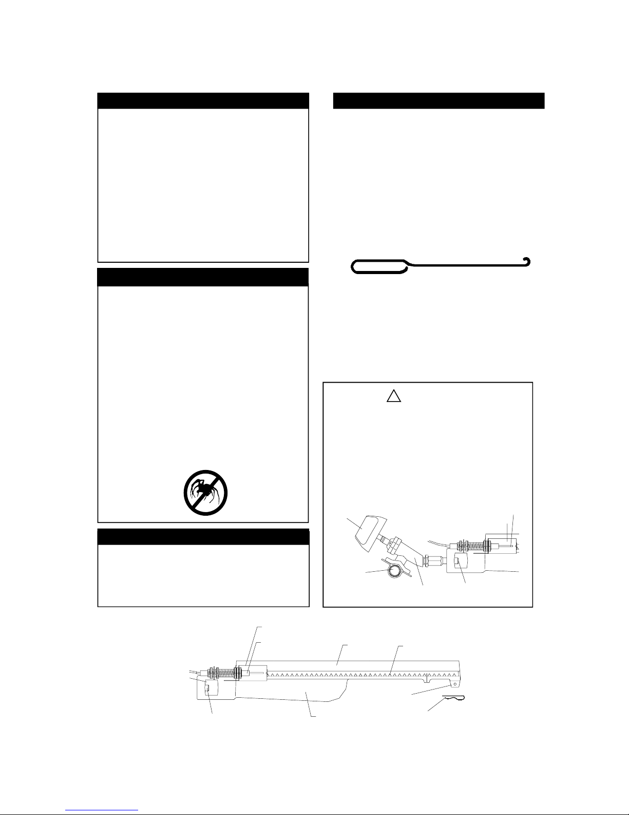
To reduce the chance of "FLASHBACK" (see
CAUTION at left) clean the Burner Tubes and
Burners before fully assembling your grill. Remove the Cotter Pin from the rear underside of
each Burner using a pair of long nose pliers.
Carefully lift each Burner up and away from the
Gas Valve Orifice, then refer to Figure 1 and
perform one of these three cleaning methods:
Bend a stiff wire, (a lightweight coat hanger
1.
works well) into a small hook as shown
below. Run the hook through the Burner
Tube and inside the Burner several times to
remove any debris.
CAUTION: BEWARE OF FLASHBACK
CAUTION: Spiders and small insects occasion-
ally spin webs or make nests in the grill burner
tubes during transit and warehousing. These webs
can lead to a gas flow obstruction which could
result in a fire in and around the Burner Tubes.
This type of fire is known as a "FLASHBACK"
and can cause serious damage to your grill and
create an unsafe operating condition for the user.
Although an obstructed Burner Tube is not the
only cause of "FLASHBACK", it is the most
comm on cause.
To reduce the chance of "FLASHBACK", you
must clean the Burner Tubes before assembling
your grill, and at least once a month in late
summer or early fall when spiders are most active.
Also perform this Burner Tube cleaning procedure
if your grill has not been used for an extended
period of time.
Tools Required for Assembly
Phillips Head screw driver
•
Long nose pliers - used to remove the
•
Cotter Pin when cleaning the Burners
Open-end wrench (included with Hardware
•
Pack) used to tighten the Casters.
Use a Burner Cleaning Brush, or a bottle
2.
brush with a flexible handle. Run the brush
through the Burner Tube and inside the
Burner several times, removing any debris.
Use an air hose to force air through each
3.
Burner Tube. The forced air should pass
debris or obstructions through the Burner
and out the ports.
WARNING!
The location of the Burner Tube with respect
to the Orifice is vital for safe operation. Check
to ensure the Orifice is inside the Burner Tube
before using your gas grill. See Figure 2.Ifthe
orifice is not inside the burner tube, lighting the
Burner may cause explosion and/or fire.
Figure 2
CONTRO L
KNOB
CROSS
SECTION
OF MANIFOLD
GAS VALVE ORIFICE
SPARKELECTRODE
GAS COLLECTOR BOX
Figure 1
TO CLEANBURNER TUBE,
INSERT HOOK HERE
ORIFICE
GAS COLLECTOR BOX
SPARKELECTRODE
BURNERTUBE
4
BURNER
BURNER PORT
FOOT
COTTER PIN
Page 5
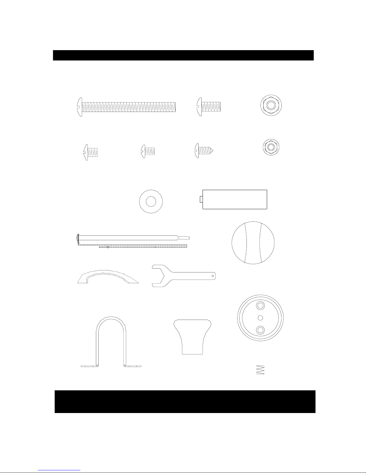
Contents for Hardware Pack (Part #P4182A)
Contents for Hardware Pack (Part #P4182A)
Contents for Hardware Pack
The following table illustrates a breakdown of the Hardware Pack. It highlights what components
are used in the various stages of assembly.
Component Qty Purpose of Components
1/4" x 1/2" Phillips Head Screw
Attach Bowl Bracket to Bowl Side Panel
4
1/4" Nut
1/4" Washer
1/4" x 1/2" Phillips Head Screw
1/4" Nut
1/4" x 1/2" Phillips Head Screw
1/4" x 1/2" Phillips Head Screw
1/4" Nut
1/4" Washer
1/4" x 2- 1/2" Phillips Head Screw
3/16" x 3/8" Phillips Head Screw
1/4" x 1/2" Phillips Head Screw
3/16" x 3/8" Phillips Head Screw
3/16" x 1/4" Phillips Head Screw
1/4" x 2- 1/2" Phillips Head Screw
1/4" Nut
3/16" x 3/8" Phillips Head Screw
1/4" x 1/2" Phillips Head Screw
M4 x 10 Self Tapping Screw
3/16" x 3/8" Phillips Head Screw
3/16" Nut
Side Burner Control Knob
Spring
Side Burner Control Knob Seat
Lighting Stick
Customized Wrench
Hose Holder
Lid Knob
4
4
Secure Side Shelf and Side Shelf Bracket
4
4
Attach Side Shelf Bracket to Crat Legs
8
Attach Side Shelf to Bowl Side Panel
4
4
4
Attaches Cart Legs to Bottom Shelf
8
Attaches Cart Rear Panel to Cart Legs
4
Attaches Door Bracket to Cart Legs
2
Attaches Door Stop to Bottom Shelf
2
Secure Door Handle to Door Plate
4
Secure Cart Legs to Grill Bowl
4
4
Attaches Cart Side Panel to Cart Legs
8
Attaches Bowl Bracket to Cart Legs
8
Attaches Lighting Stick to Grill Bowl
1
Attaches Hose Holder to Cart Side Panel
2
2
Attaches on Side Burner Valve
1
Attaches on Side Burner Valve
1
Attaches on Side Burner Valve
1
Attaches on RR Cart Leg
1
Tighten Caster
1
Secure Regulator Hose on the Cart Side Panel
1
Attaches on Side Burner Lid
1
5
Page 6
Contents for Hardware Pack (Part #P4182A)
Contents for Hardware Pack (Part #P4182A)
Contents for Hardware Pack P06021002A
Quantity of Each Hardware Piece:
1/4" x 2 1/2" Phil lips Head Screw
QTY: 12
3/16" x 1/4"
Phillips Head Screw
QTY. 4
(found in Door Handle)
1/4" W asher
QTY. 8
Manual Lighting Stick - QTY. 1
3/16" x 3/8"
Phillips Head Screw
QTY: 16
1/4" x 1/2"
Phillips Head Screw
QTY: 30
M4 x 10
Self-T apping S crew
QTY. 1
"AA" Battery - QTY. 1
Side Burner Control Knob
-QTY. 1
1/4" Lock Nut
QTY: 16
3/16" Lock Nut
QTY: 2
Door Handl e - QTY . 2
Hose Holder- QTY. 1
Grill Information Center: If you have questions about assembly or grill operation, or if there are
damaged or missing parts when you unpack this unit from the shipping boxes, call us
8:00am - 5:00 pm EST, Monday through Friday at:
Caster Wrench - QTY. 1
Side Burner Control Knob Seat
-QTY. 1
Lid K nob- QTY. 1
Spring - QTY. 1
1- 800-667-7313
6
Page 7
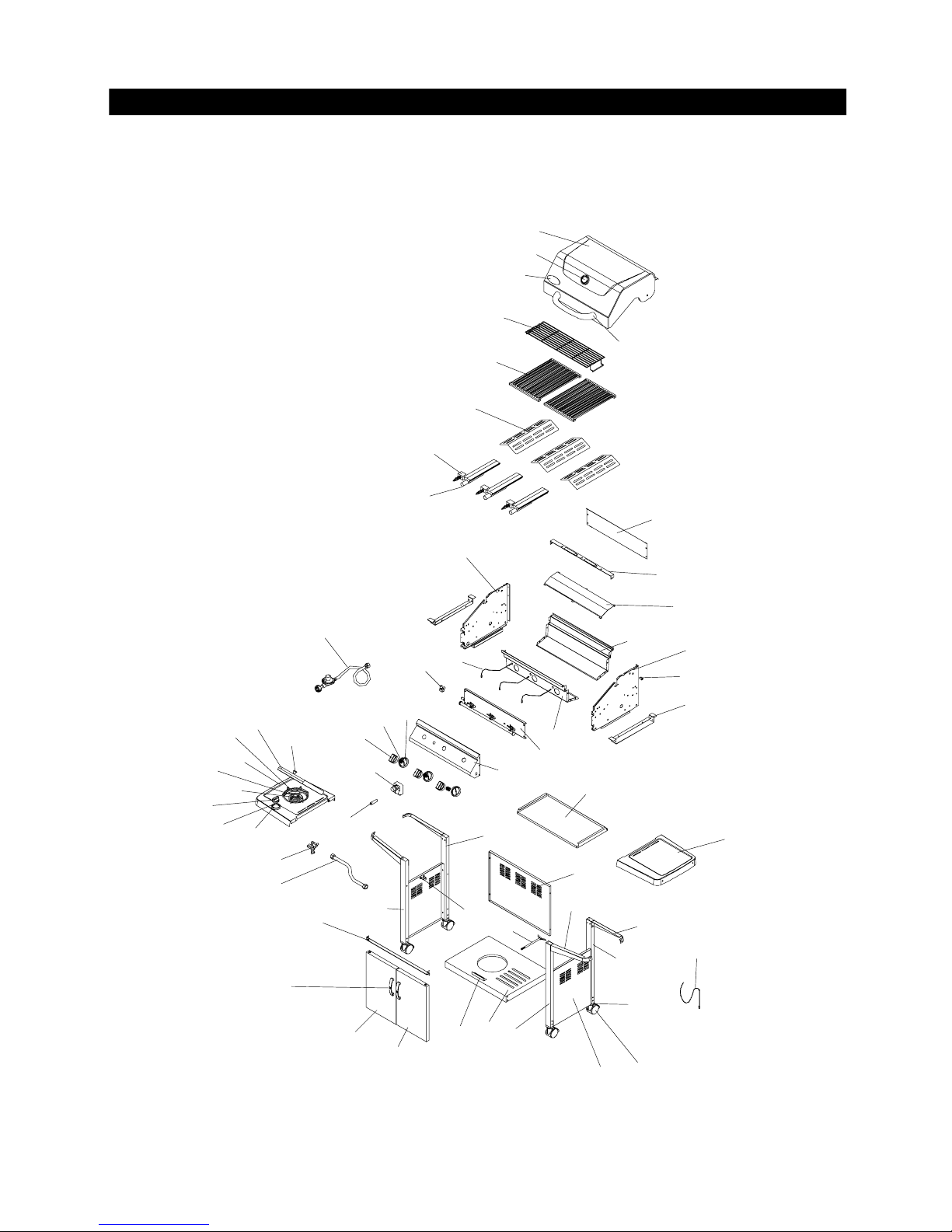
SS54 Parts Diagram
Remove all components from the carton and place within easy reach. Turn carton upside down
and it will provide a comfortable height work surface for grill assembly.
1
2
3
5
4
6
7
8
9
45
51
53
23
50
47
52
48
54
55
56
49
41
44
40
26
42
24
25
31
23
43
22
20
18
39
12
29
38
30
59
21
33
19
15
36
28-1
27
37
32
13
34
35
10
11
14
16
17
46
28
57
7
Page 8
Lid Plate
1.
Heat Gauge
2.
Name Plate
3.
Lid Handle
4.
Warming Rack
5.
Cooking Grid
6.
Flame Tamer
7.
Gas collector with Electrode
8.
Main Burner
9.
Burner Bracket
10.
Grease Tray Heat Shield, Upper
11.
Bowl Panel, Left
12.
Bowl Panel, Rear
13.
Bowl Panel, Right
14.
Bowl Panel, Front
15.
Lid Hinge
16.
Bowl Bracket
17.
Electric Wire Set
18.
Gas Valve/ Manifold
19.
Assembly
Gas Fitting
20.
Control Panel
21.
Control Knob Seat
22.
Spring
23.
Control Knob
24.
Ignitor - 4 port
25.
Battery
26.
Grease Tray
27.
Side Shelf Bracket-A
28.
Side Shelf Bracket-B
28-1.
Hose Holder
29.
Cart Leg,LR
30.
Cart Leg,LF
31.
Cart Leg,RR
32.
Cart Leg,RF
33.
Caster Seat
34.
Caster
35.
Cart Rear Panel
36.
Cart Side Panel
37.
Bottom Shelf
38.
Door Stop
39.
Door Bracket
40.
Door Handle
41.
Door Panel, Left
42.
Door Panel, Right
43.
LPG Regulator
44.
Bowl Wind Shield
45.
Side Shelf, Right
46.
Side Burner Frame
47.
Side Burner Lid
48.
Side Burner Lid Handle
49.
Pot Support
50.
Side Burner
51.
Side Burner Electrode
52.
Side Burner Control Knob
53.
54.
Side Burner Control Knob
Seat
SS54 Parts List
P0011819EA
P00601061A
P00414039C
P00202004A
P01505005G
P01615015A
P01705006E
P02609002B
P02001009E
P0220310DD
P06903019B
P0072009JA
P0072513FA
P0072109JA
P0073813FA
P05501005F
P01306013D
P02615012A
Y0060118
P03906002A
P02907231P
P03415041J
P05504001A
P03411011C
P02502134C
P05301001A
P02705075B
P01204001C
P01206001C
P05536001G
P00911009C
P00910009C
P00913009C
P00912009C
P04507001A
P05112002A
P07702024B
P07604007B
P01002009D
P05510009G
P03301013D
P00201001C
P04302019A
P04303019A
P03601003A
P06905008A
P01103006D
P02302004D
P01127003B
P00202005A
P00805002F
P02002007A
P02614007C
P03420121K
P03408051J
QTY.REF# PAR T#DESCRIPTION
55.
1
1
1
1
1
2
3
3
3
1
1
1
1
1
1
2
2
1
1
1
1
3
4
3
1
1
1
2
2
1
1
1
1
1
4
4
1
2
1
1
1
2
1
1
1
1
1
1
1
1
1
1
1
1
1
Side Burner Gas Valve
56.
Connection Hose
57.
Lighting Stick
58.
Grease Tray Heat Shield,Lower
59.
Wing Bolt
Y0060127
P03705014A
P05507031E
P06903021B
S233G03371
CSA Label
For the repair or replacement parts you need:
Call our Customer Service Dept., 8am - 5pm EST,
Monday through Friday at 1-800-667-7313
To make sure you obtain the correct replacement part
(s) for your gas grill please refer to the parts list on
this page. The following information is required to
insure you receive the correct parts:
1. Model and Serial Number (see CSA label on grill)
2. Part Number
3. Description
4. Quantity of parts needed
Please allow sufficient time to process and ship.
IMPORTANT: Keep this Owner's Manual for
convenient referral and for part replacement.
IMPORTANT: Use only factory authorized parts. The
use of any part that is not factory authorized can
be dangerous. This will also void your warranty.
QTY.REF# PART#DESCRIPTION
1
1
1
1
1
8
Page 9
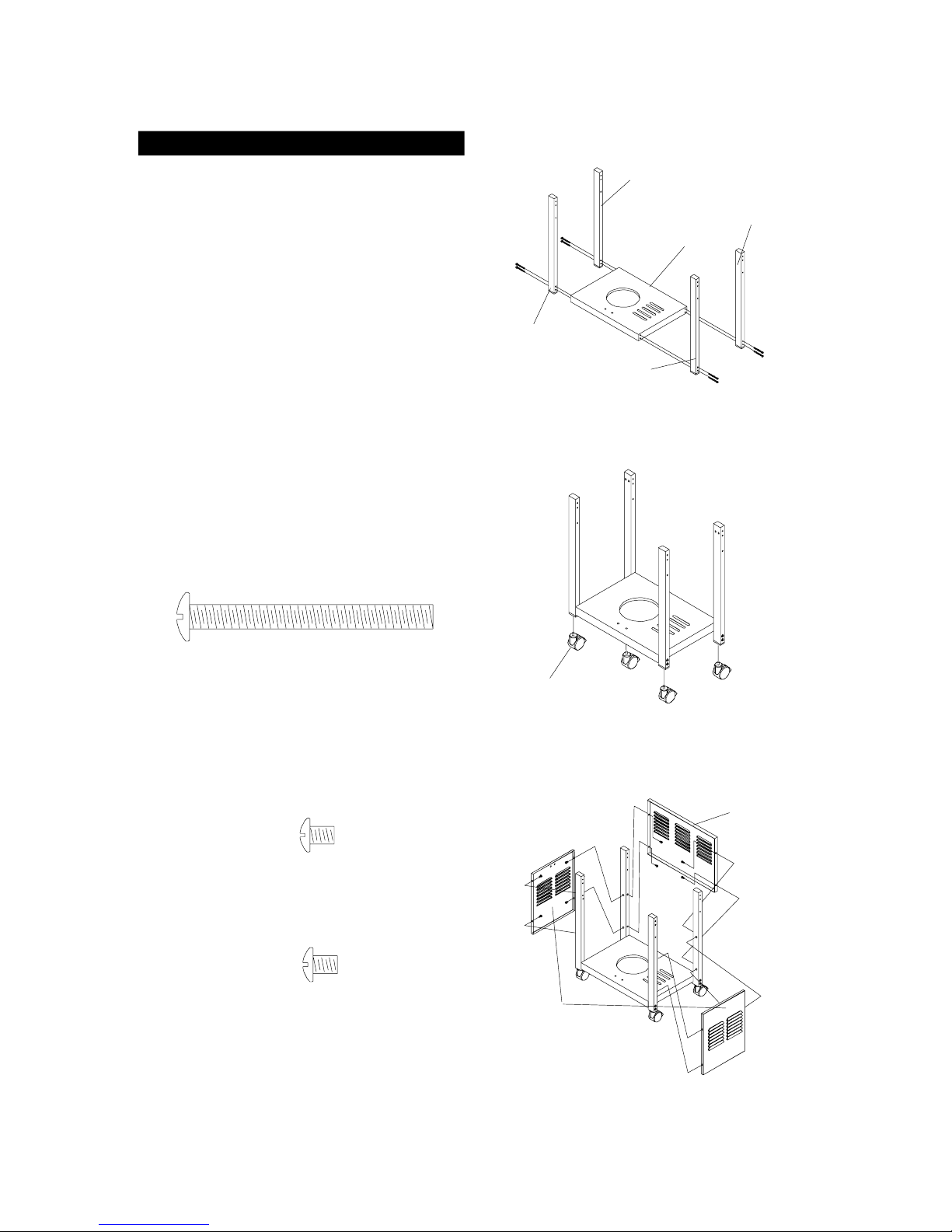
Cart Assembly Instructions
Remove all cart parts, hardware, and Grill Head from
shipping boxes. Raise the Grill Lid and remove all
packed components. Use the parts list to check that
all necessary parts have been included.
Assemble the gas grill on a protective work surface
to avoid scratching grill surfaces. Inspect your grill for
damage as you proceed. Do not assemble or operate
your grill if it appears damaged.
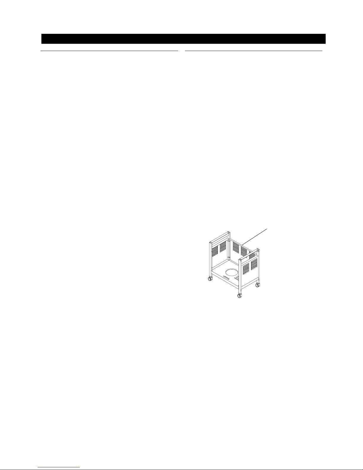
Assembling The Cart
1.
Position bottom shelf with tank toward the left
side.See Figure 1.
Note: The label on the cart legs indicate their
assembly position to the bottom shelf. LF=Left
Front, LR=Left Rear, RF=Rear Front, and
RR= Right Rear. Labels should face inward
toward each other when correctly assembled.
Remaining components cannot be assembled if
leg postions are incorrect.
2.
Install the four cart legs to the indicated corners
of the bottom shelf using 8 of the 1/4" x 2-1/2"
Phillips Head screws provided. Do not fully tighten
screws.
Figure 1
CART LEG
(LF)
Figure 2
CART LEG
(LR)
CART LEG
(RF)
BOTTOM
SHELF
CART LEG
(RR)
1/4" x 2-1/2" Phillips Head Screw x 8
3.
Screw the 4 Casters into the caster seats in the
bottom of each cart leg. Turn the threaded caster
stem by hand, clockwise unit it stops. Fully tighten.
With the wrench provided. See Figure 2.
4.
Install the two Cart Side Panels to the cart by using
4 of the 3/16" x 3/8" Phillips Head screws on each
panel.
See Figure 3.
3/16" x 3/8" Phillips Head Screw x 8
5.
Install the Cart Rear Panels to the cart
by using 4 of the 3/16" x 3/8" Phillips Head screws.
3/16" x 3/8" Phillips Head Screw x 4
CASTER
Figure 3
CART REAR
PANEL
CART SIDE
PANEL
9
Page 10
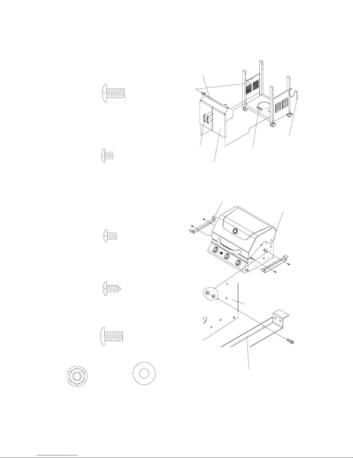
Attach the Door Bracket to the low holes in the
6.
front legs with the end tabs pointing upward and
flange to the rear, pointing downward. Use 2 of
1/4" x 1/2" Phillips Head Screws. Do not fully
tighten. See Figure 4.
1/4" x 1/2" Phillips Head Screw x 2
7.
Attach the Door Stop to the bottom shelf, with
the flange facing the front, using 2 of
3/16" x 3/8" Phillips Head Screws. Fully tighten.
See Figure 4.
Figure 4
DOOR BRACKE T
DOOR
HANDLE
LIGHTING
STICK
DOOR S TOP
3/16" x 3/8" Phillips Head Screw x 2
Place doors into the hinge holes of the bottom shelf
8.
and Door Bracket. Push Door Bracket down until
doors are secure and can open and close freely.
Do not full tighten Door Bracket screws. See
Figure 4.
Remove protective film from Doors. Install Door
9.
Handle to Doors using 4 of 3/1 6" x 1/ 4" Phillips Head
Screws. See Figure 4.
3/16" x 1/ 4"
Phillips Head Screw x 4
(found in door handle)
Attach lighting stick to the Right Rear Leg, below
10.
side shelf bracket using 1 M4 x 10 self-tapping
screw.
M4 x 10 Self-Tapping Screw x 1
11.
Attach the 2 Bowl Brackets to Bowl Side Panel
using 4 of 1/4" x 1/2" Phillip Head Screw, 1/4" Nuts
and 1/4" W asher s. Ful ly tighten. See Figure 5.
DOOR PLATE
Figure 5
BOWL BRACKE T
BOWL PANEL
BOWL SIDE PANE L
1/4" x 1/2" Phillips Head Screw x 4
1/4" Lock Nut x 4
BOWL BRACKE T
1/4" W asher x 4
10
Page 11
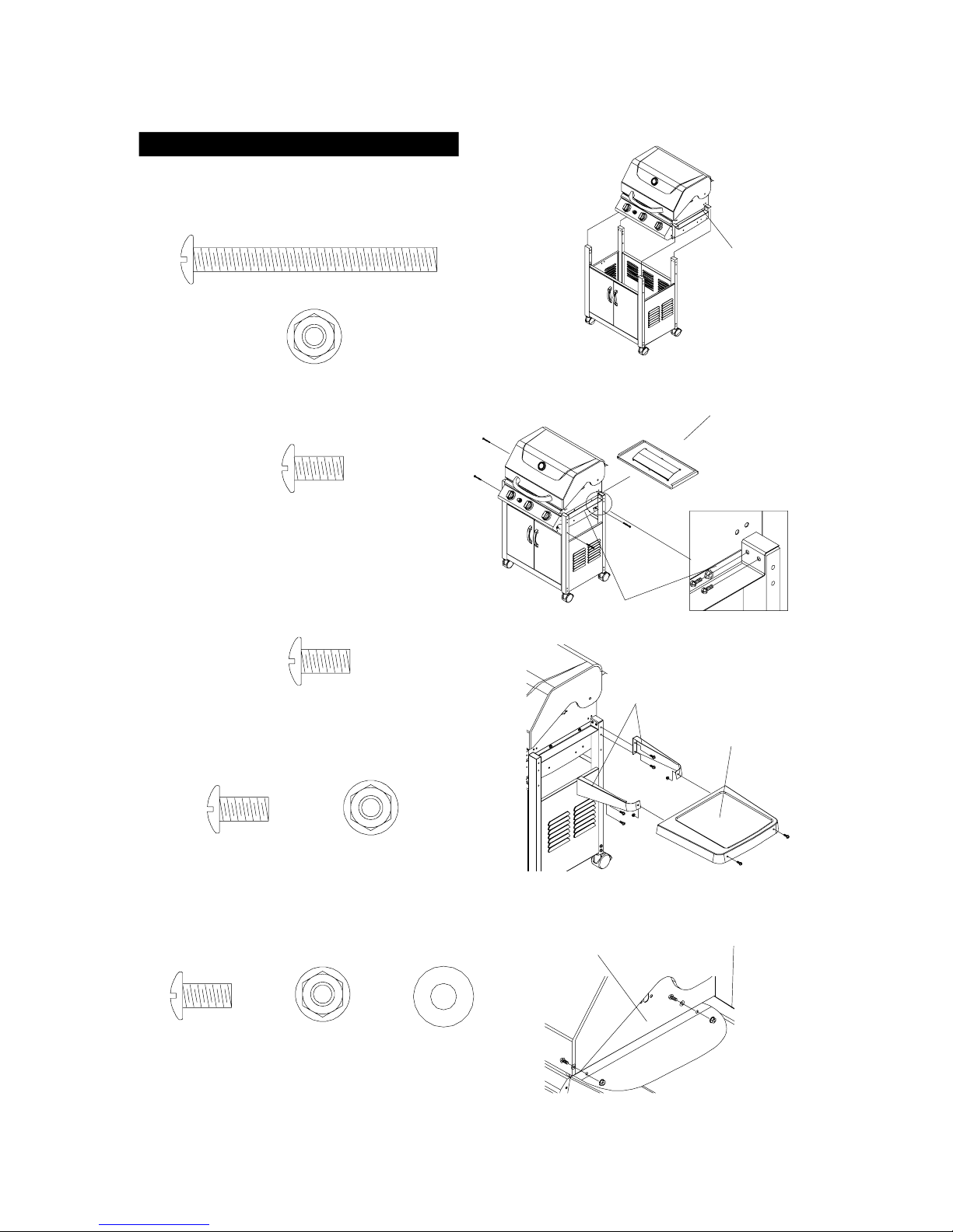
Grill Head Assembly
Put the grill head onto cart. Secure grill head to
12.
all cart legs using 4 of 1/4" x 2-1/2" Phillips Head
Screws and 1/4" Nuts. See Figure 6,7.
1/4" x 2-1/2" Phillips Head Screw x 4
Figure 6
GRILL BOWL
1/4" Lock Nut x 4
13.
Secure Bowl Bracket to Cart Legs using 4 of 1/
4" x 1/2" Phillips Head Screws. Repeat this step
for the other side. See Figure 7.
1/4" x 1/2" Phillips Head Screw x 8
Fully tighten all leg screw, Rear Panel Screws,
14.
Door Bracket screws and grill head screws.From
the back of the cart, slide the grease draining tray
into the grill head.
15.
Attach the Side Shelf Brackets to Cart Leg using
8 of 1/4" x 1/2" Phillips Head Screws. See Figure
8.
1/4" x 1/2" Phillips Head Screw x 8
16.
Place the Side Shelves over the Side Shelf
brackets. Secure firmly using 4 of 1/4" x 1/2"
Phillips Head Screws and 1/4" Lock Nuts.See
Figure 8.
Figure 7
GREASE TRAY
BOWL BRACKE T
Figure 8
SIDE SHELF BRACKET
SIDE SHELF
1/4" x 1/2" Phillips
Head Screw x 4
Align the Side Shelf holes to Bowl Side Panel and
17.
Side Shelf Bracket. Secure firmly by using 1/4"
x 1/2" Phillips Head Screws, 1/4" Nuts and 1/4 washers.
1/4" x 1/2" Phillips
Head Screw x 4
1/4" Lock Nut x 4
1/4" Lock Nut x 4
1/4" Washer x
4
11
Figure 9
BOWL PANEL
SIDE SHELF
Page 12
Was
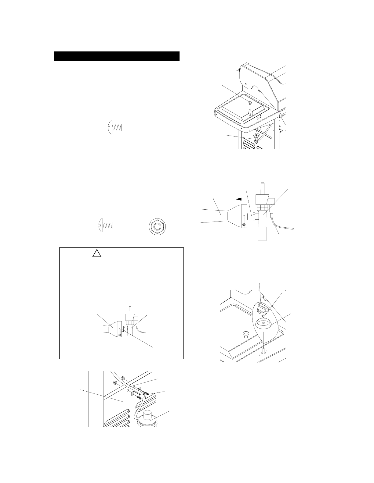
Side Burner Assembly
Insert the Orifice into the Side Burner Tube.
18.
AttachtheSideBurnerGasValvetoSideShelf
Left. Secure firmly using 2 of M4 x 10mm Phillips
Head Screws (Attached on Side Burner Gas Valve).
Attach the Side Burner Electrode Wire to the
Control Valve.See Figure 10,11.
Install the Lid Knob using 1 of 3/16" x 3/8" Phillips
19.
Head Screw (attaches on Lid Knob).See Figure
10.
3/16" x 3/8" Phillips Head Screw x 1
Attach the chrome color Control Knob Seat and
20.
Spring onto the Gas Valve stem. Then, carefully
attach the Control Knob so the "OFF" position
faces upward - toward you. Do not force the Control
Knob onto the stem. See Figure 12.
21.
Place the LPG Regulator inside the cart through
the opening above Cart Side Panel. Press the hose
of the LPG Regulator into the Hose Holder above
Cart Side Panel. Secure firmly using 2 of 3/16"
x 3/8" Phillips Head Screw and 3/16" Nut. See
Figure 13.
Figure 10
LID KNOB
SIDE BURNER
GAS VALVE
Figure 11
SIDE BURNER
TUBE
ORIFICE
SIDE BURNER
GAS VALVE
3/16" x 3/8"
Phillips Head Screw x 2
3/16" Lock Nut x 2
WARNING!
The location of the Burner Tube with respect to
the Orifice is vital for safe operation. Check to
ensure the Orifice is inside of the Burner Tube
as shown below, before using your gas grill. If
the Burner Tube does not fit over the Valve
Orifice, lighting the Burner may cause an explosion and/or fire. Figure 3A
Burner Tube
Figure 13
CART SIDE
PANEL
GAS VALVE
ORIFICE
ELECTRODE
WIRE
Figure 12
CONTROL
KNOB
SPRING
CONTROL
KNOB SEAT
HOSE
HOSE HOLDER
LPG REGULATOR
12
Page 13
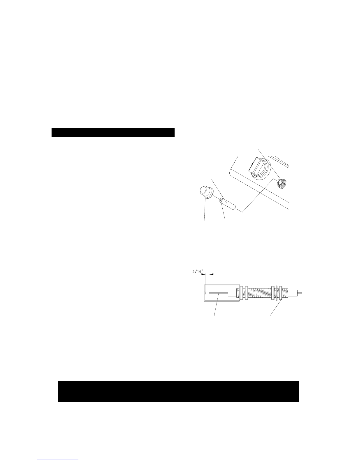
Ignitor Battery Installation - See Figure 14
1. Unscrew the Ignitor Cap located on the Grill Control
Panel and remove the Contact and Spring from the
Ignitor Slot.
5. If no "clicking" sound is heard check the
following common causes. If you need
assistance call our Grill Information Center
at 1-800-667-7313.
2. Place the manufacturer supplied AA battery into the
Ignitor Slot. Be sure to place the positive pole facing
toward you.
3. Place the Spring over the AA battery, then place
the Contact on top of the Spring. Screw the Ignitor
Cap back onto the grill Control Panel.
Electrode Check
Requires and assistant:
Before placing the cooking components into your grill,
insure that the Spark Electrode Tip is properly positioned
within each Gas Collector Box (stainless steel mechanism found at the front between each set of Burners.)
The easiest way to insure this is to perform this Electrode
Check:
1. Be sure all Control Knobs are set to "OFF"
and open the Grill Lid.
2. Have an assistant stand behind to the right of
the grill and look down at each Gas Collector
Box. NEVER put your face inside Grill Head.
3. Push Ignition Cap. You should hear a clicking
sound and your assistant should see a small
blue spark within each Gas Collector Box.
If a spark is present the Elect rode Tips are
properly positioned.
4. If no spark is seen the Spark Gap shown in
Figure 15 needs to be adjusted as follows:
Ignitor AA battery not installed properly.
Ignitor wires may be loose. Remove the AA
battery, inspect the Ignitor Junction Box
found behind the Control Panel, and connect
any loose wires.
Figure 14
IGNITOR SLOT
AA B AT TER Y
IGNIT OR CAP
Figure 15 - Side View Gas Collector Box
+
• Using an adjustable wrench, loosen the inside
Nut just until the Gas Collector Box can be
maneuvered and turned upward.
SPARK GAP
• The gap between the Spark Electrode Tip and
Spark receiver should be approximately 3/16".
• If the gap is wider than 3/16" use a pair of long
hose pliers and gently squeeze the Gas
Collector Box until the gap is correct.
SPARK
ELECTRODE TIP
INSIDE
NUT
• Return the Gas Collector Box to its original
horizontal position, secure the inside Nut and try
the Electrode Check again.
Grill Information Center: If you have questions about assembly or grill operation, or if there are
damaged or missing parts when you unpack this unit from the shipping boxes, call us
8:00am - 5:00 pm CST, Monday through Friday at:
1-800-667-7313
13
Page 14
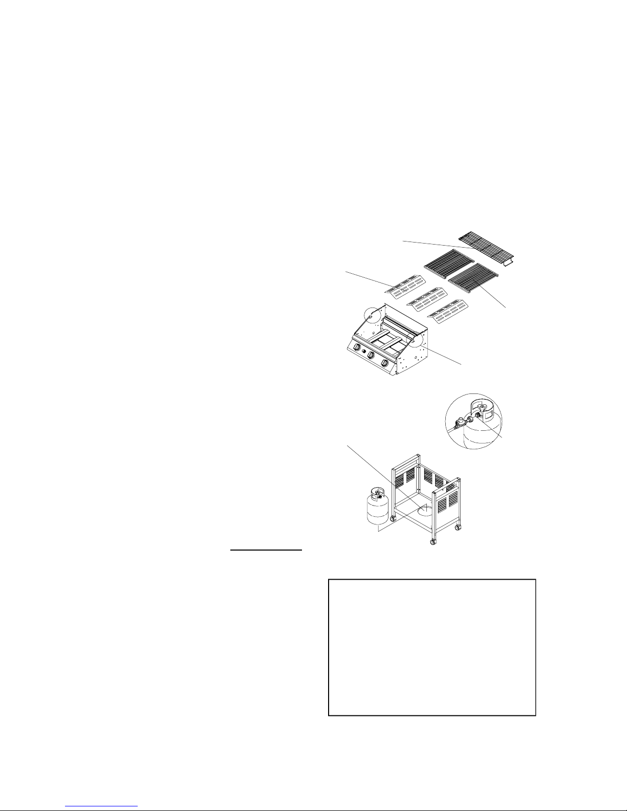
Installing Cooking Components
1.
Place the Flame Tamers on the lower ledge above
Burners. See Figure 16. Place 3 of Flame Tamers
onto the Rack.
2.
Place Cooking Grids on the ledge above Flame
Tamers.
3.
Place Warming Rack into the slot on the upper
left and upper right of the grill bowl panels. See
Figure 16.
Disconnecting A Liquid Propane Gas (LP gas)
Tank From Your Grill
1.
Turn the Burner Valves and LP Gas Tank Valve
to the full OFF position (turn clockwise to
close).
2.
Detach the Hose and Regulator Assembly from
the LP gas Tank Valve by turning the Quick
Coupling Nut counterclockwise.
IMPORTANT: The Grill is not designed for use with
lava rock or briquettes and the use of such items
will void the warranty.
Connecting A Liquid Propane Gas (LP gas)
Tank To Your Grill
1. Check the Tank Valve to insure it has proper
external mating threads to fit the Hose and
Regulator Assembly provided. (Type 1
connection per ANSI Z21.58a-2002)
2. Inspect the Valve Connection Port and
Regulator assembly. Look for damage or debris.
Remove any debris. Inspect Hose for dam age.
Never use damaged or plugged equipment.
3. Hang your filled gas tank on the Tank Hole.
4. Make sure all Burner Valves are in the OFF
position.
5. When connecting the Hose and Regulator
Assembly to the Tank Valve, hand tighten nut
clockwise to a full stop. Do Not use a wrench
to tighten because it could damage the Quick
Coupling Nut and result in a hazardous
condition.
Figure 16
WARMINGRACK
FLAME
TAMERS
Figure 17
TANK HOLE
Cooking Grid
Theseholesare for
Rotisserie Mounting Bracket use
TYPE 1
CONNECTION
PER ANSI Z21.
58A-2002
6. Slowly open the tank valve 1
(counterclockwise). Use a soapy water solution
to check all connections for leaks before
attempting to light your grill. See "Checking
for Gas Leaks" on page 15. If a leak is found,
turn the Tank Valve off and do not use your
grill until the leak is repaired. Do this leak test
even if the grill was store assembled.
/4 to 1/ 2 op en
CAUTION: When the appliance is not in use, the
gas must be turned off at the supply tank.
Congratulations
Your Grill Chef gas grill is now ready for use.
Before the first use and at the beginning of each
season (and whenever a LP gas tank
has been changed):
Read all safety, lighting and operating
1.
instructions.
2.
Check Gas Valve Orifices, Burner Tubes and
Burner Ports for any obstructions.
Perform gas leak check according to
3.
instructions found on page 15 of this
Owner's Manual.
14
Page 15
!
WARNING
A strong gas smell, or the hissing sound of gas
indicates a serious problem with your gas gri ll
or the LP gas tank. Failure to immediately follow
the steps listed below could result in a fire or
explosion that could cause serious bodily injury,
death, or property damage.
• Shut off gas supply to the gas grill.
• Turn the Control Knobs to OFF position.
• Put out any flame with a fire extinguisher.
• Open Grill Lid.
• Get away from the LP gas tank.
• Do not try to fix the problem yourself.
• If odor continues or you have a fire you
cannot extinguish, call your fire department.
Do not call near the LP gas tank because
your telephone is an electrical device and
could create a spark resulting in fire and/
or explosion.
NOTE: The normal flow of gas through the
regulator and hose assembly can create a
humming nosie. A low volume of nosie is
perfectly normal and will not interfere with
operation of the grill . If hum ming nosie is
loud and excessive you may need to purge
air from the gas line or reset the regulator
excess gas flow device. Thi s purg ing
procedure should be done every time a new
LP gas tank is connected to your grill. For
help call the Customer Service Helpline for
assistance.
Grill Lighting Instructions
Basic Lighting Procedures
Familiarize yourself with the safety guidelines
1.
at the front of this manual. Do not smoke
while lighting grill or checking gas supply
connections.
Be sure the LP gas tank is filled.
2.
3.
Check that the end of each Burner Tube is
properly located over each valve orifice.
4.
Make sure all gas connections are securely
tightened..
5.
Open the Grill Lid.
!
Failure to open Grill Lid during the lighting
procedures could result in a fire or explosion
that could cause serious bodily injury, death,
or property damage.
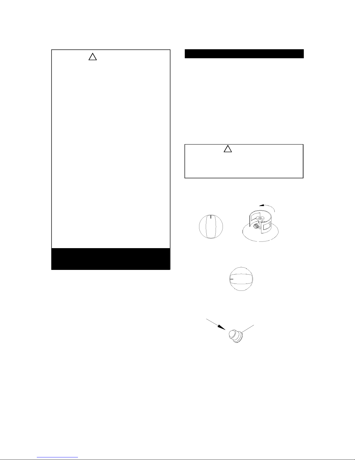
Set control knobs to OFF and open the LP gas
6.
tank valve slowly until 1/4 to 1/2 open.
OFF
WARNING
Open LP
gas tank
Customer Service Helpline, 8:00am - 5:00
pm EST, Monday through Friday at
1-800-667-7313.
Checking For Gas Leaks
Never test for leaks with a flame. Prior to first use,
at the beginning of each season, or every time your
LP gas tank is changed, you must check for gas leaks.
Follow these four steps:
1.2.Makeasoapsolutionbymixingonepartliquid
detergent and one part water.
Turn the grill Control Knobs to the full OFF
position, then turn the gas ON at source.
3.
Apply the soap solution to all gas connections.
If bubbles appear in the soap solution the connections are not properly sealed. Check each
fitting and tighten or repair as necessary.
4.
If you have a gas leak that you cannot repair,
turn off the gas at the source, disconnect fuel line
from your grill and call 1-800-667-7313 or your gas
supplier for repair assistance.
15
7.
Push and turn the RIGHT control knob to HIGH.
OFF
HIGH
8.
Immediately press the electric ignitor for 3-4
seconds to light the burner.
PRESS
9.
If the burner does not light, turn the control knob to
OFF, wait 5 minutes for gas to clear, then retry.
10.
Once the right grill burner is ignited, the adjacent
burner can be lit by simply turning its control knob
to HIGH.
Adjust control knobs to your desired cooking
11.
temperature.
ELECTRIC
IGNITOR
Page 16
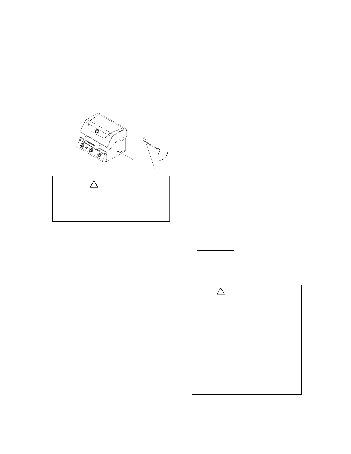
Manually Lighting Your Grill by Match
To light your gas grill by match, insert a match into the
Manual Lighting Stick and follow steps 1 through 6 of the
Basic Lighting Procedures. Then, light the match and
place Manual Lighting Stick through the Lighting Holeon
the right side of the grill. See Figure 18. Turn thenearest
Main Burner Control Knob to the HIGH setting to release
gas. The Burner should light immediately.
Figure. 18
LIGHTING
HOLE
MANUAL
LIGHTING
STICK
MATCH
WARNING!
Never lean over the grill cooking area while
lighting your gas grill. Keep your face and body
a safe distance (at least 18 inches) from the
Lighting Hole or Burners, when lighting your grill
by match.
If the grill fails to light properly:
1.
Turn gas off at source and turn the Control Knobs
to OFF. Wait at least five minutes for gas to clear,
then retry.
2.
Check gas supply and connections.
3.
Repeat lighting procedure. If your grill still fails to
operate properly, turn the gas off at source, turn the
Control Knobs to OFF, then check the following:
Misalignment of Burner Tubes over Orifices
•
Correction: Reposition Burner Tubes over Orifices.
Obstruction in gas line
•
Correction: Removefuel linefrom grill. Do not smoke!
Open gas supply for one second to clear any
obstruction from fuel line. Close offgas supplyat source
and reconnect fuel line to grill.
Plugged Orifice
•
Correcti on: Remove Burners from grill by pulling
Cotter Pin (beneath Burner) using Long nose
pliers. Carefully lift each Burner up and away
from Gas Valve Orifice. Remove the Orifice from
Gas Valve and gently clear any obstruction with
a fine wire. Then reinstall all Orifices, Burners,
Cotter Pins and cooking components.
If an obstruction is suspected in Gas Valves or Gas
Valve Bracket, please call the Customer Service
Dept. at 1-800-667-7313.
•
Misalignment of Ignitor on Burner
Correction: Check for proper position of the
Electrode Tip as shown on page 13. The gap
between the Spark Electrode Tip and Spark
Receiver should be approximately 3/16".
Adjust if necessary following the Electrode
Check procedure on page 13.
•
Disconnected Ignition Wires
Correcti on: Inspect the Ignitor Junction Box
found behind the Control Panel. Connect loose
Ignitor wires to Junction Box and try to light
grill.
Weak AA battery
•
Correction: Unscrew the Ignitor Cap and replace
the battery.
To purge air from your gas line and/or reset
the Regulator excess gas flow device:
Opening the tank valve all the way or too quickly is
what triggers the Regulators safety device to shut
down gas flow which prevents excessive gas flow to
your grill. Lighting the Burner farthest from the fuel
source every time will help eliminate air pockets in
the Manifold. This procedure should be done every
time a new LP gas tank is connected to your grill:
Turn all Control Knobs to the OFF position.
Turn off the LP gas tank valve at the tank
valve.
Disconnect Regulator from LP gas tank.
Let unit stand for 5 minutes.
Reconnect Regulator to the LP gas tank.
Open Grill Lid or Side Burner Lid.
Turn the LP gas tank valve on s
1/4 to 1/2 open.
ight the Burner farthest from fuel source
L
by turning its Control Knob to HIGH then
pushing in the Control Knob. To light the
Side Burner push its Control Knob in and
turn to HIGH.
WARNING
!
Should a "FLASH-BACK" fire occur in/or
around the Burner Tubes, follow the
instructions below. Failure to comply with
these instructions could result in a fire or
explosion that could cause serious bodily
injury, death, or property damage.
• Shut off gas supply to the gas grill.
• Turn the Control Knobs to OFF position.
• Put out any flame with a Class B fire
extinguisher.
• Open Grill Lid.
• Once the grill has cooled down, cl ean
the Burner Tubes and Burners according
to the cleaning instructions found on
page 18 in this manual.
lowly until
16
Page 17

Cleaning and Maintenance
Keeping outdoor cooking gas appliance area clear
and free from comustible materials, gasoline and
other flammable vapors and liquids.
As with all appliances, proper care and
maintenance will keep your grill in top operating
condition and prolong its life. By following these
cleaning procedures on a timely basis, your grill will
stay clean and work properly with minimum effort.
CAUTION:
Be sure your grill is OFF and cool before cleaning.
Cleaning The Cooking Grids
Before initial use and as needed, wash your Grids
with a mild detergent and rinse with hot water. For
stubborn food residue use a degreaser and fiber or
brass cleaning brush.
Cleaning The Grease Tray and Receptacle
To reduce the chance of fire, the Grease Draining
Tray, Grease Receptacle and Heat Shield should be
inspected before each grill use. Remove grease
(a plastic spatula works well) and wash Grease Tray
and Receptacle with a mild soap and warm water
solution.
Cleaning the Flame Tamers
To reduce the chance of flare-ups, Flame Tamers
should be cleaned whenever food or grease drippings accumulate. Brush off Flame Tamers with a
fiber type brush and turn over to allow the burner
heat to burn off any stuborn food residue. The
Ceramic Flame Tamers work equally well on
either side.
Annual Cleaning of The Grill Interior
Use a fiber or brass cleaning brush to cl ean the
interiorGrill Bowl, Cooking Grids, Flame Tamers and
grease containers. On porcelain finished parts never
use a wire brush or metal scraper which can scratch
or chip the porcelain finish and promote rusting.
1. Turn all Control Knobs to the full OFF position.
Cover each gas ValveOrifice with aluminum foil.
5.
Brush the inside and bottom of the grill with a
6.
brass wire brush or fiber cleaning pad, and wash
with a mild soap and warm water solution. Rinse
thoroughly and let dry.
7.
Remove aluminum foil from Orifices and check
each Ori fice for obstruction.
Check eachSpark Electrode, adjusting as needed.
8.
The space between the Spark Electrode Tip and Spark
Receiver should be approximately 3/16".
Replace the Burners and adjust the gas collector
9.
box. The edge of the collector box should be
overlapping the Burner Port.
Replace Flame Tamers and the Cooking Grids.
10.
Reconnect the gas source and observe the Burner
11.
flame for correct operation.
Exterior Stainless Steel Surfaces:
Weathering and high heat can cause a stainless
steel grill Lid to turn tan in color. This is not to be
confused with rust and is not a product defect.
Machine oils used in the manufacturing process of
stainless steel as well as cooking oils and a dirty
grill Lid can also encourage discoloration if the Lid
is not cleaned prior to grill use.
1. Shut off gas supply at source and disconnect
fuel line from Gas Valve Manifold. Protect fuel
line fitting.
2. Use a Stainless Steel Cleaner and soft cloth to
remove residual adhesive and oils from the in
side and outside of your grill Lid. Never use
abrasive cleaners or scrubbers. In addition to
the initial cleaning, routine cleaning to remove
dirt, grease and oils will help discourage Lid dis
coloration.
2. Turn the LP gas Tank Valve to the full OFF position.
3. Detach the LP gas Regulator assembly from your gas
grill or disconnect the Quick Disconnect Hose from the
gas source.
4. Remove and clean the Flame Tamers, Cooking
Grids, and Grill Burners.
Grill Information Center: If you have questions about assembly or grill operation, or if there are damaged
or missing parts when you unpack this unit from the shipping boxes, call us 8:00am - 5:00 pm EST, Monday
through Friday at:
1- 800-667-7313
17
Page 18
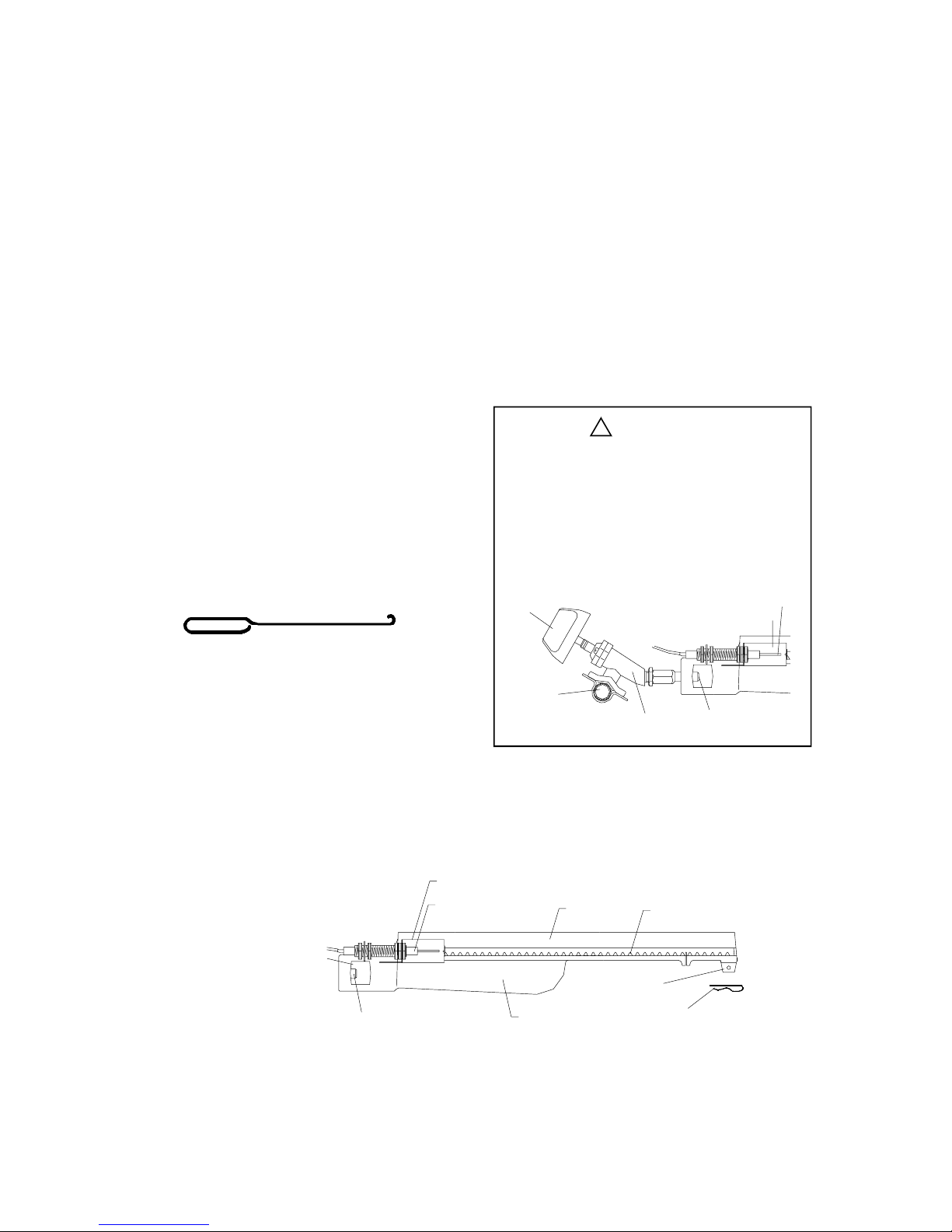
Cleaning The Burner Tubes and Burner Ports
To reduce the chance of "FLASH-BACK" you must
clean the Burner Tubes at least once a month in late
summer or early fall when spiders are most active or
when your grill has not been used for an extended
period of time.
Turn all Control Knobs to the full OFF position.
1.
2.
Turn the LP gas Tank Valve to the full OFF position.
Detach the LP gas Hose and Regulator Assembly
3.
from your gas grill.
Remove the Cooking Grids, Flam e Tamers, and
4.
Grease Trays from your grill.
Remove theCotter Pin from the rear underside of each
5.
Burner using a pair of long nose pliers.
Carefully lift each Burner up and away from the
6.
gas Valve Orifice.
Refer to Figure 1 and perform one of these
7.
three cleaning methods:
Bendastiffwire,(alightweightcoat
•
hanger works well) into a small hook as
shown below. Run the hook through the
Burner Tube and inside the Burner several
times to remove any debris.
Regardless of which Burner cleaning procedure you
use, we recommend you also complete the
following steps to help prolong Burner life.
1.
Use a wire brush to clean the entire outer
surface of each Burner until free of food residue
and dirt.
Clean any clogged ports with a stiff wire, such
2.
as an open paper clip.
Inspect each Burner for damage (cracks or
3.
holes) and if such damage is found, order and
install a new Burner. After installation, check to
insure that the Gas Valve Orifices are correctly
placed inside the ends of the Burner Tubes.
Also check the position of your Spark
Electrode.
!
WARNING
The location of the Burner Tube with respect
to the Orifice is vital for safe operation. Check
to ensure the Orifice is inside the Burner Tube
before using your gas grill. See Figure 2.Ifthe
orifice is not inside the burner tube, lighting the
Burner may cause explosion and/or fire.
Figure 2
CONTRO L
KNOB
SPARKELECTRODE
GAS COLLECTOR BOX
Use a Burner Cleaning Brush or a bottle
•
brush with a flexible handle. Run the brush
through the Burner Tube and inside the
Burner several tim es, removing any debris.
Use an air hose to force air through each
•
Burner Tube. The forced air should pass
debris or obstructions through the Burner
and out the ports.
Figure 1
TO CLEANBURNER TUBE,
INSERTHOOK HERE
ORIFICE
CROSS
SECTION
OF MANIFOLD
GAS COLLECTOR BOX
SPARKELECTRODE
BURNERTUBE
BURNER
GAS VALVE
BURNER PORT
FOOT
COTTER PIN
ORIFICE
18
Page 19

Frequently Asked Questions
Question: Can I convert my grill from LPG to NG?
Answer: No, your gas grill is manufactured to exact
specifications and is certified for Liquid Propane (LPG)
or Natural Gas (NG) use only. For your safety,
conversion kits are not available. Any attempt to
convert your grill will void your warranty.
Question: The Hose and Regulator supplied with my
grill does not fit the older LPG tank I've used for years.
Answer: U.S. Government regulates gas appliances
and LP gas tanks. When regulations are changed the
LP gas tank fittings are altered to insure compliance.
If your LP gas tank does not fit the Hose and
Regulator supplied with your new gril l, the tank is
outdated and must be replaced. Note: Effective April
1, 2002 all LP gas tanks sold must include an OPD
Overflow Protection Device. This internal device
prevents the LP gas tank from being overfilled. Tanks
without an OPD val ve can not be refi lled.
Question: Are the serial and model numbers of my grill
listed somewhere for future reference?
Answer: The model and serial numbers are listed on
a Silver Label placed on the Control Panel bottom
right-hand side. If your grill features a Side Burner, it
will have its own silver label and a model number
ending in SB. This is not the primary grill model
number or serial number needed for Product Warranty
Registration or for Customer Support purposes.
Question: What causes grill parts to rust and what af
fect does it have on the grill materials.
Answer: Rusting is a natural oxidation process and may
appear on cast-iron and steel parts. Rust will not affect short
term performance of your grill. Stainless steel grill parts will
not rust. However, weathering and extreme heat can cause
a stainless steel Lid to turn tan color. This is discoloration
and is not considered a manufacturing defect.
Question: My grill does not light properly. Why?
Answer: Always light theBurner farthest from the fuel source
first. This d ra ws gas across t he Manifold hel ping prev ent air
pockets which obstruct gas flow. Also check these causes:
Check LP gas supply. An empty LP gas tank weights
about 20 pounds. A full tank weighs about 40 pounds.
Check to insure all gas connections are secure.
The Ignition AA battery may need replacing.
Ignition wires may be loose. Removethe battery, inspect
the Ignitor Junction Box found behind the Control Panel
and connect any loose wires.
Spark Electrode Tips may need repositioning. Refer to
the electrode Check” procedures found on page 15.
Check that the end of each Burner Tube is
properly located over each Gas Valve Orifice.
There may be an obstruction in the gas line. To correct
this, remove LP gas Hose and Regulator or Natural Gas
fuel line from your grill. Do not smoke! Open gas supply
for one second to clear any obstruction from fuel line.
Close off gas supply at source and reconnect fuel line to
your grill.
If an obstruction is suspected in the Orifice or Gas
Valves, call the Customer Service Helpline, at
1-800-667-7313.
Question: My grill has a low flame and sometimes
will not light. Why?
Answer: You need to purge air from the gas line or reset
the Regulator excess gas flow device. Opening the tank
valve all the way or too quickly triggers the Regulators
safety device to shut down gas flow which prevents
excessive gas flow to your grill. Lighting the Burner
farthest from the fuel source every time will help eliminate
air pockets in the Manifold. Perform this procedure every
time a new LP tank is connected to grill:
Turn all Control Knobs to the OFF position.
Turn off the LP gas tank valve.
Disconnect Regulator from LP gas tank.
Let unit stand for 5 minutes.
Reconnect Regulator to the LP gas tank.
Open Grill Lid or Side Burner Lid. Turn the
tank valve on s
Light the Burner farthest from fuel source by
turning its Control Knob to IGN then pushing
in the Control Knob. To light the Side Burner
push its Control Knob in and turn to HIGH.
Question: Sometimes I hear a humming sound
coming from my Regulator. What causes this?
Answer: The humming sound is gas flowing through
the Regulator. A low volume of sound is normal and will
not interfere with the operation of your grill. If the
humming sound is loud and excessive you need to purge
air from the gas line or reset the Regulator excess gas
flow device as described above.
Question: How and when do I clean the interior
cooking components of my grill?
Stainless Steel Cooking Grids: Before initial useand
as needed, wash Grids with a mild detergent and rinse
with hot water. For stubborn food residue usea degreaser
and fiber or brass cleaning brush.
Flame Tamers: To reduce the chance of flare-ups,
Flame Tamers should be cleaned whenever food
or grease drippings accumulate. Brush off
Flame Tamers with a fiber type brush and turn
over to allow the burner heat to burn off any
stuborn food residue. The Ceramic Flame Tamers
work equally well on either side.
Grease Tray, Receptacle and Heat Shield:
To reduce the chance of fire, the Grease Draining
Tray, Grease Receptacle and Heat Shield should
be inspected before each grill use. Remove grease
(a plastic spatula works well) and wash Grease
Tray and Receptacle with a mild soap and warm
water solution.
Question: What causes a stainless steel to discolor?
Answer: Weathering and high heat can cause a
stainless steel grill Lid to turn tan in color. This is not to
be confused with rust and is not a product defect.
Machine oils used in the manufacturing process of
stainless steel, cooking oils and a dirty grill Lid can
also encourage discoloration if the Lid is not cleaned
prior to grill use. After your grill is assembled, remove
the protective PVC film from the grill Lid and use a
Stainl ess Steel Cl eaner and soft cloth to remove
residual adhesive and oils from the inside and outside
of your grill Lid. Never use abrasive cleaners or
scrubbers. Routine cleaning to remove dirt, grease and
oils will help discourage Lid discoloration.
lowly until 1/4 to 1/2 open.
19
Page 20
Cooking Instructions
WARNING!
Your grill will get very hot. Never lean over
the cooking area while using your grill. Do
not touch cooking surfaces, grill housing,
Grill Lid or any other grill parts while the grill
is in operation, or until the grill has cooled
down after use.
Failure to comply with these instructions
may result in serious bodily injury.
Burn-off
Before cooking on your gas grill for the first time, you
will want to "burn off" the grill to eliminate any odor or
foreign matter. Just ignite the Burners, lower the Lid,
and operate grill on the HIGH setting for three to five
minutes.
CAUTION:
Operating your grill on the HIGH setting for longer than
five minutes may damage certain parts of your grill. Do
not leave your grill unattended.
Preheating
To preheat, light your grill on HIGH, lower the lid and
follow this timetable:
For high temperature cooking, preheat grill
•
3 to 5 minutes.
For low temperature cooking, preheat grill
•
3 minutes.
To slow cook, preheating is not necessary.
•
Indirect Cooking
The indirect cooking method can also be used with
the supplied cooking grids. To cook indirectly,
the food should be placed on the left or right side
of your grill with the burner lit on the opposite side.
Indirect cooking must be done with the lid
down.
Flare-Ups
The fats and juices dripping from grilled food can
cause flare-ups. Since flare-ups impart a favorably,
distinctive taste and color to food cooked over an
open flame, they should be accepted up to a point.
Nevertheless, uncontrolled flaring can
result in a ruined meal.
!
WARNING
Do not line the bottom of the grill housing
with aluminum foil, sand or any substance
that will restrict the flow of grease i nto
the grease draining tray and receptacle.
Failure to compl y with these instructions
could result in a fire or explosion which
could cause serious bodily injury, death,
or property damage.
Cooking Temperatures
High setting: Only use this setting for fast warm-up,
searing steaks or chops and for burning food
residue off the grill after cooking is complete. Never
use the HIGH setting for extended cooking.
Medium to Low settings: Most recipes specify
medium to low settings, including alls moking,roasting,
baking and for cooking lean cuts such as fish.
NOTE: Temperature settings will vary with theamount
of wind and temperature outside your home.
Direct Cooking
The direct cooking m ethod can be used with the
supplied Cooking Grids and food placed directly
over the lit grill Burners. Direct cooking requires
thegrilllidtobeup.This m ethod is ideal for
searing and whenever you want meat, poultry or fish
to have an open-flame barbecued taste. Deep frying
and smoking are also best cooked in this manner
because they require direct heat.
20
Page 21

LIMITED WARRANTY
S.R. POTTEN Ltd. warrants to the original owner
of each Grill Chef Gas Grill that it is free from
defects in workmanship and materials under
conditions of normal residential use. S.R. Potten
Ltd. will repair or replace warranty parts
according to the list on page 2 of this manual.
The extent of any liability of S.R. Potten Ltd.
under this limited warranty is limited
to repair or repl acement. The limited warranty
period is not extended by such repair or
replacement. S.R. Potten Ltd. is not liable for
any labor or other costs related to the
removal and/or installation of any Warranty
Part, installation of replacement parts, product
assembly, and/or delivery costs.
S.R. Potten Ltd. requires reasonable proof of your
date of purchase. Therefore, you should retain your
sales slip or invoice and return the S.R. Potten Ltd.
Product Warranty Registration Card immediately.
This limited warranty does not apply to any damage
due to transportation, installation, purchaser
servicing, accident, abuse, fire, alteration of the
product in any way, act of God, or failure to read
and/or abide by any product warnings, or any parts
or labor used to replace any part or parts covered
under this limited warranty.
In no event, whether as a result of breach of
Warrantyor Contract,negligence,strictliabitity,or
misrepresentation, will S.R.POTTEN Ltd. be liable
for any incidental and/or consequential damages.
S.R. Potten Ltd.'s liability is limited to the
purchase price of the covered grill.
S.R. Potten Ltd.does not assume, or authorize any
other person to assume for S.R. Pott en Ltd. any
liability from the sale of this product beyond
that expressly set forth in this Limited Warranty.
For Warranty Service, please call our
Customer Service Department at
1-800-667-7313, Monday through Friday,
8:00 AM TO 5:00 PM EST.
21
S.R. POTTEN LTD/LTÉE
th
1645 – 50
AVENUE
LACHINE,QUÉBEC, CANADA
H8T 3C8
 Loading...