

Page 1
12739A
Version: 12739Auk
reVision: #199-2010
edition: 01/10cd
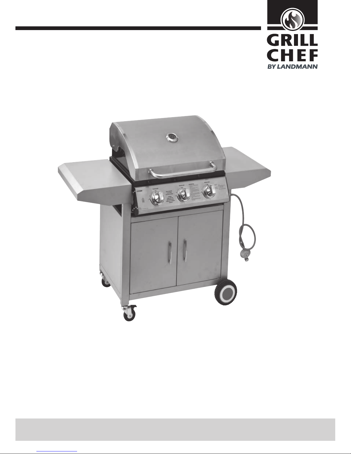
"Kitchen gas barbecue"
Assembly and operating manual
Please read before starting!
Failure to observe these instructions can aect or damage the device and other objects and lead to personal injury.
We therefore recommend that you read the relevant chapter of these instructions prior to assembly and be-
fore each use. Follow the steps in the order they are specied and please observe the safety warnings.
These instructions form part of the product. They should therefore always be sto-
red with the product and passed on to each subsequent user.
Page 2

2
GRILLCHEF
Table of contents
Technical specications ...............................................................................................................................3
Delivery specications.................................................................................................................................4
Pack of xing bolts ...............................................................................................................................4
Exploded view .............................................................................................................................................5
Operational elements ..................................................................................................................................6
Function ......................................................................................................................................................6
Utilisation ...................................................................................................................................................7
Warranty and disclaimer .............................................................................................................................7
Safety instructions ......................................................................................................................................8
Denition of terms used .......................................................................................................................8
Danger "Hot surfaces and parts" ..........................................................................................................9
Danger "Gas is highly ammable" ......................................................................................................10
Danger "Gas displaces oxygen" ..........................................................................................................11
Assembly ..................................................................................................................................................12
Assembly procedure ..................................................................................................................................13
Connecting and disconnecting the gas cylinder ........................................................................................17
Connecting the gas cylinder ...............................................................................................................18
Operation ..................................................................................................................................................20
Starting up the barbecue ....................................................................................................................20
Switching o the barbecue .................................................................................................................21
Cleaning ....................................................................................................................................................22
Barbecue ............................................................................................................................................22
Lava rocks ...........................................................................................................................................22
Gas system .........................................................................................................................................22
Maintenance .............................................................................................................................................23
Environmental information and disposal measures ..................................................................................23
Troubleshooting ........................................................................................................................................24
Instructions for using liquid gas cylinders .................................................................................................26
Declaration of conformity .........................................................................................................................27
Page 3
3
GRILLCHEF
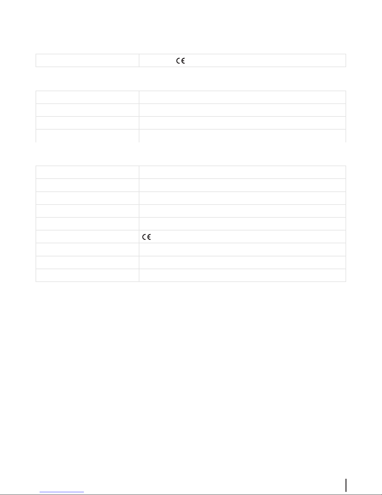
Technical specications
Approvals
ITS Test number - 0359, Pin/no. 359BU1021
Barbecue
Appliance category I3+ according to DIN EN 498
Total weight approx. 38 kg
Dimensions (L x H x W) approx. 1280 x 1045 x 560 mm
Grilling surface (L x W) 2 x approx. 454 x 295 mm
Gas system
Heat output 10.5 kW
Mass ow rate 765 g/h
Gas type Liquid gas (propane/butane)
Gas cylinder Standard gas cylinder with a ll weight of 3, 5 or 11 kg
Gas pressure 28-30 mbar at butane, 37 mbar at propane
Gas hose -approved hose (max 1.5 m)
Ignition Piezo ignition
Flame regulator innitely adjustable 0 - max.
Nozzle diameter 0.9 mm
Page 4
4
GRILLCHEF
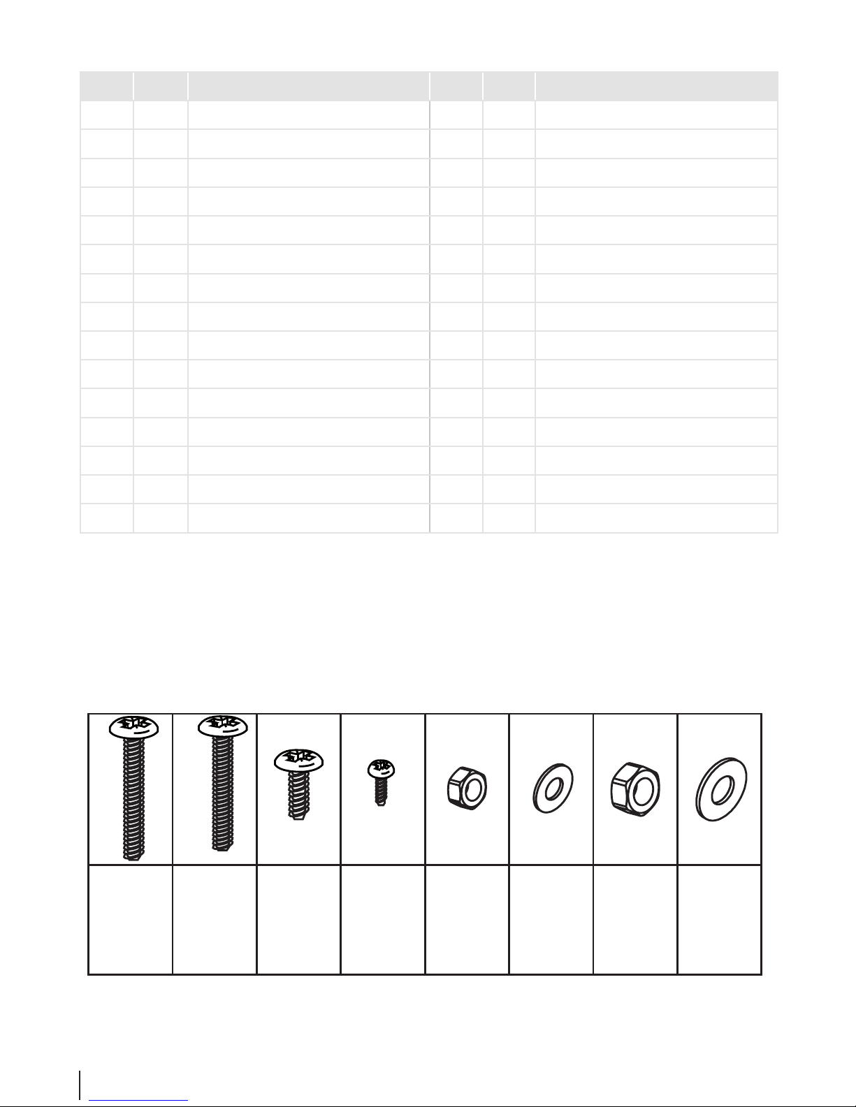
Pack of xing bolts
M8
2x
Ø8
4x
M4x10
4x
M6x70
8x
M6x10
16x
M6x60
4x
A
C
G
M6
4x
E
D
B
H
Ø6
4x
F
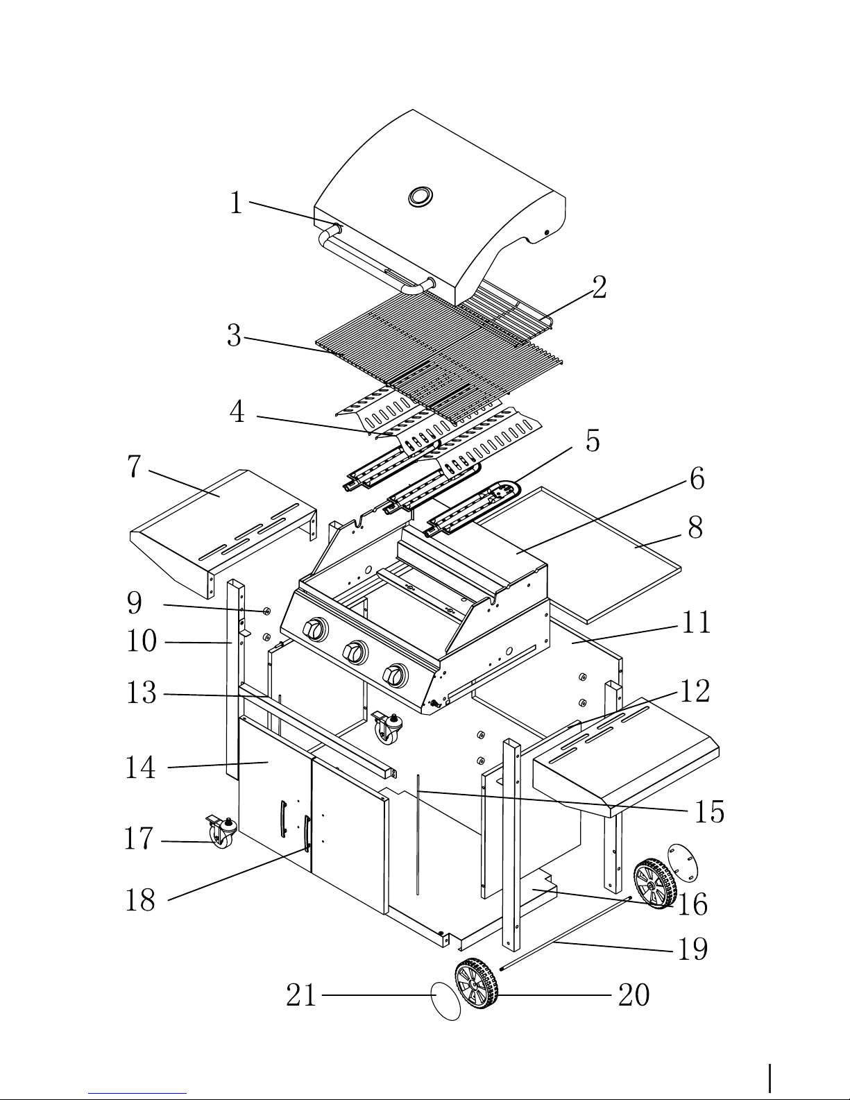
Delivery specications
Pos*. Qty. Description Pos.* Qty. Description
1 1 Lid 16 1 Lower shelf
2 1 Warming rack 17 2 Locking wheel
3 2 Cooking grill 18 2 Door handle (pre-assembled)
4 3 Flame guard 19 1 Wheel axle
5 3 Burner 20 2 Wheel
6 1 Grill unit (pre-assembled) 21 2 Wheel cap
7 2 Side rack
8 1 Fat collection tray
9 8 Spacer
10 4 Wheel leg
11 1 Rear panel
12 2 Side panel
13 1 Front cross bar
14 2 Door
15 2 Door pin
Page 5
5
GRILLCHEF
Exploded View
Page 6
6
GRILLCHEF
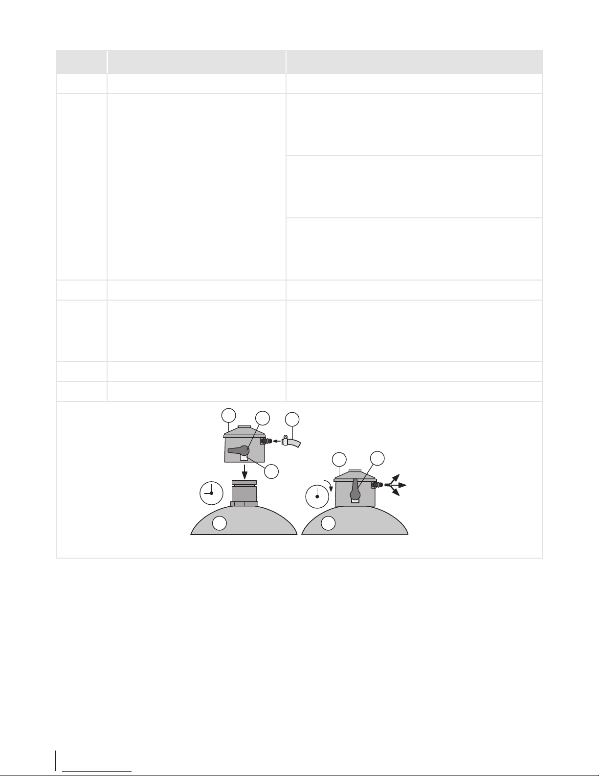
Controls
Pos. Designation Function
A Piezo igniter Ignite gas on burner (press).
B Flame regulator left Fill burner with gas to ignite (keep depressed and turn to "lar-
ge ame" setting).
After ignition adjust the heat input for the left burner (turn).
middle (2 - 5) Fill burner with gas to ignite (keep depressed and turn to "lar-
ge ame" setting).
After igniting set the heat output for the centre burner (turn).
right Ignite the right burner (keep depressed briey and turn to "lar-
ge ame" setting).
After ignition adjust the heat supply for the right burner (turn).
G1 Pressure reducer Reduce gas pressure.
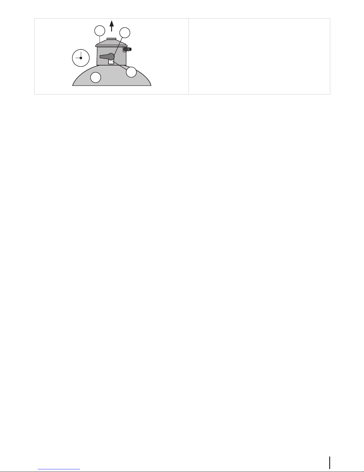
G2 control button with safety catch Cut-o safety device with 2 settings:
9 o'clock setting: gas o / shut o gas cylinder
12 o'clock setting: Gas is on.
G3 gas cylinder with bottle valve Fuel container
G4 Gas hose with hose clip Directs gas to burner.
G5
12
G1
G3
9
G2
G1
G2
G4 G4
Page 7

7
GRILLCHEF
Utilisation
Intended use
This is a gas barbecue that is intended for outdoor use. It is designed to be used exclusively in accordance with these instructions for preparing food that is suitable for barbecuing and these instructions must be observed at all times.
Only for private use!
Improper use
Any other application or applications extending beyond the stated purpose are not authorised. This applies to the following
types of misuse in particular:
• Do not operate the barbecue with coal or fuel other than liquid gas (propane/butane).
• Do not operate the barbecue as a stove with pots and pans.
• Do not operate the barbecue as a heater.
Do not use the barbecue to heat materials and substances other than food that is suitable for barbecuing.
Warranty and disclaimer
The barbecue has been manufactured according to the general engineering rules - valid at the time manufacturing was
started - and the requirements of the - sign. It is certied and approved by ITS (test number -0359). The barbecue left
the factory in perfect condition regarding its function and safety.
This barbecue is covered by our warranty for a period of two years from the date of purchase. This warranty covers manufacturing defects and faulty parts as well as the replacement of these parts. The cost of freight, assembly, replacement of worn
parts, and other such costs are not covered by this warranty.
The warranty shall expire and any responsibility shall pass over to the executor:
• if the barbecue is not used properly.
• if the barbecue is used despite visible damage or if it is not completely assembled.
• if any technical alterations have been made to the barbecue.
• if accessories are used that are not expressly authorised for this barbecue (if in doubt please contact our customer
service department).
• if original spare parts from LANDMANN GmbH & Co. Handels-KG are not used.
Page 8

8
GRILLCHEF
Safety instructions
Denition of terms used
The following pictograms and signal words are used in these instructions to point out hazards and important information.
Safety instructions
Pictogram and signal word Note on ...
Danger
... a possible danger that can result in severe personal injury or damage
to property if the stated measures are not observed.
Caution
... a possible danger that can result in damage to property if the specied measures are not observed.
Operating notes
Pictogram Note on ...
... a useful function or tip.
Page 9

9
GRILLCHEF
Danger "Hot surfaces and parts"
During operation some parts of the barbecue can become very hot, particularly those that
are close to the re bowl.
Possible consequences:
• Severe burns from touching parts near the re bowl.
• Fire or smouldering re if ammable materials or substances are near the barbecue.
Safety measures prior to using the barbecue:
• When setting up the barbecue, make sure that
– there are not, and will not be, any ammable materials or substances nearby. Mi-
nimum distance to ammable materials or substances: 2 m above and 1 m to the
side. Distance to highly ammable materials or substances, e.g. walls: min. 0.25 m.
– the barbecue is positioned rmly on a suciently large surface area. It must not be
moved during operation.
Safety measures while barbecueing:
• Wear protective barbecue gloves.
• Never leave the barbecue unattended. Take particular care to ensure that children and
pets are kept away from the barbecue.
Page 10

10
GRILLCHEF
Danger "Gas is highly ammable"
Liquid gas is highly ammable and explosive.
Possible consequences:
• Serious personal injury or damage to property if escaping gas ignites in an environment
in which it is not controlled.
Safety measures:
• Only use the barbecue outdoors and ensure that the area is well-ventilated.
• Protect the gas cylinder and the gas hose from direct sunlight and other sources of heat
(max. 50°C). Take particular care to ensure that the gas hose does not touch any part of
the hot barbecue.
• Do not place the gas cylinder on the lower shelf, as it is too near the burner.
• Do not lean over the barbecue when igniting the gas ame.
• Close the valve on the gas cylinder immediately after each use (turn the valve clockwise).
• Never leave the barbecue unattended. If the ame extinguishes, relight immediately or
cut o the supply from the gas cylinder.
• When connecting the gas cylinder make sure that there are no sources of ignition within
a 5 m radius.
Take special care not to light any naked ames, do not smoke or switch on electric appliances (devices, lights, door bells), etc. (sparkover possible).
• Before each use, make sure that all gas connections are sealed and intact.
If necessary, replace the hose in order to comply with the corresponding national requirements.
The barbecue must not be used if the connections for the gas supply are porous or faulty.
This also applies, for example, to hoses or ttings blocked by insects, as this can produce
a dangerous ashback.
Page 11

11
GRILLCHEF
Danger "Gas displaces oxygen"
Liquid gas is heavier than oxygen. Therefore it settles on the ground and displaces the oxygen
at that level.
Possible consequences:
• Suocation resulting from a lack of oxygen if the gas concentration is allowed to rise
suciently.
Safety measures:
• Only use the barbecue outdoors in a well ventilated area and above ground (i.e. not in
areas that are below ground level).
• Close the valve on the gas cylinder after each use.
• Never leave the barbecue unattended. If the ame extinguishes, relight immediately or
cut o the supply from the gas cylinder.
• Before each use, make sure that all gas connections are sealed and intact.
If necessary, replace the hose in order to comply with the corresponding national requirements.
The barbecue must not be used if the connections for the gas supply are porous or faulty.
• If the barbecue is not being used for a prolonged period, cut o the supply from the gas
cylinder and store properly:
– Fit the gas cylinder valve with a cap nut and safety cap.
– Do not store the gas cylinder in rooms below ground level, in or near stairways,
hallways or passages and thoroughfares between buildings.
– Always store gas cylinders upright, even if they are empty.
Page 12

12
GRILLCHEF
Assembly
Before starting
Here are a few tips to help you assemble your barbecue quickly and successfully:
• Check that no parts are missing by placing all of the individual parts on an empty surface (we reserve the right to make
minor technical alterations, such as the content of the small parts bag).
If, despite careful factory checks, a component is missing, please contact our customer service department (see the last
page). We will immediately attend to your request.
• Sort out the small parts, as some of the screws and bolts, for example, are very similar and can be easily confused.
• For assembly you will need a medium size screwdriver and a suitable spanner (at spanner or box spanner).
You will need a at spanner (AF17) to connect the gas cylinder.
Only use tools that are intact and suitable for the job at hand. Worn or unsuitable tools will not allow you to tighten the
bolts suciently, but will damage them to the extent that they can no longer be turned.
• Always t all connecting elements (screws, bolts, nuts, etc.) as shown in the following illustrations. If you misplace a
connecting element, replace this with an appropriate part. Only by doing this can you ensure that the construction is
strong and safe.
• It is essential that you follow the instructions in the order they are specied!
• Read the text for each step before carrying it out, as useful information is sometimes only provided at the end of the section.
Even if you are not experienced at DIY, assembly does not generally take more than one hour.
Page 13
13
GRILLCHEF
Assembly procedure
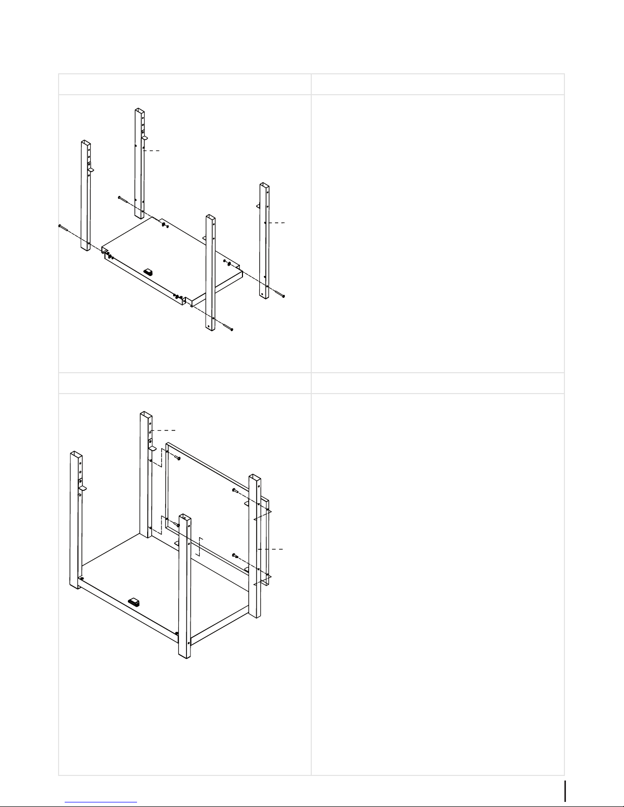
Assembly step 1
• Screw the left and right wheel legs (10) to the base
of the cart (16) using M6x60 bolts, Ø6 washers and
M6 nuts. When doing this always make sure that two
identical legs (10) are used for the left and right side
(see illustration).
Assembly step 2
• Secure the rear panel (11) between the wheel legs
(10) using M6x10 bolts.
16
10
10
11
10
10
Page 14
14
GRILLCHEF
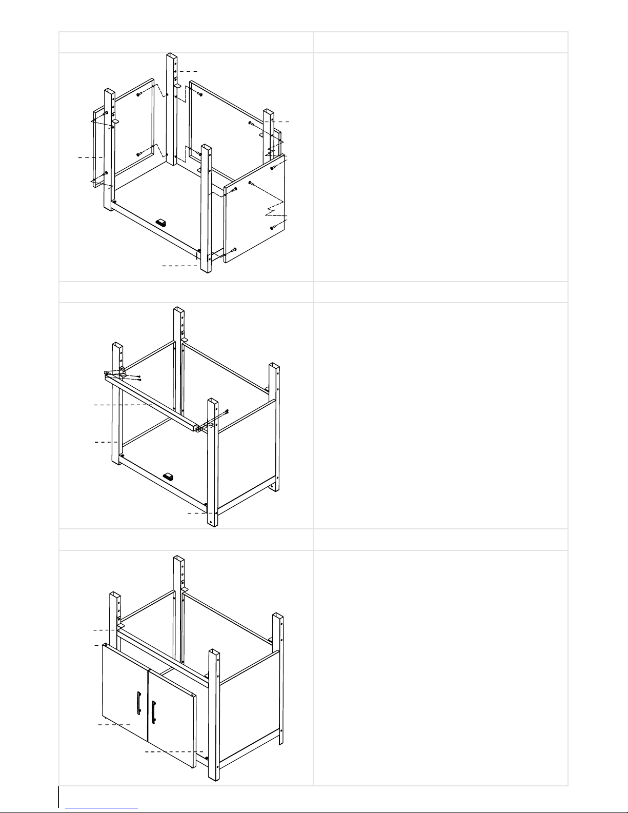
Assembly step 3
• Now insert the side panels (12) between the wheel
legs (10) and screw these in place using M6x10 bolts.
Assembly step 4
• Screw the front cross bar (13) to the left and right
wheel leg (10) by using M4x10 bolts (see the illustration).
Assembly step 5
• Insert both doors (14) into the cart as shown in the
illustration. When doing this insert the door pin (16)
through the inner holes of the door (14). Now position
the door (14) between the front cross bar (13) and the
lower shelf (16). Then insert the door pin (15) into the
upper hole in the front cross bar (13) and let the door
pin (15) drop into the lower hole in the shelf (16). Repeat this process with the other door (14).
• Check to make sure the doors (14) can be opened and
closed easily.
10
10
10
10
12
12
13
10
10
14
13
16
15
Page 15
15
GRILLCHEF
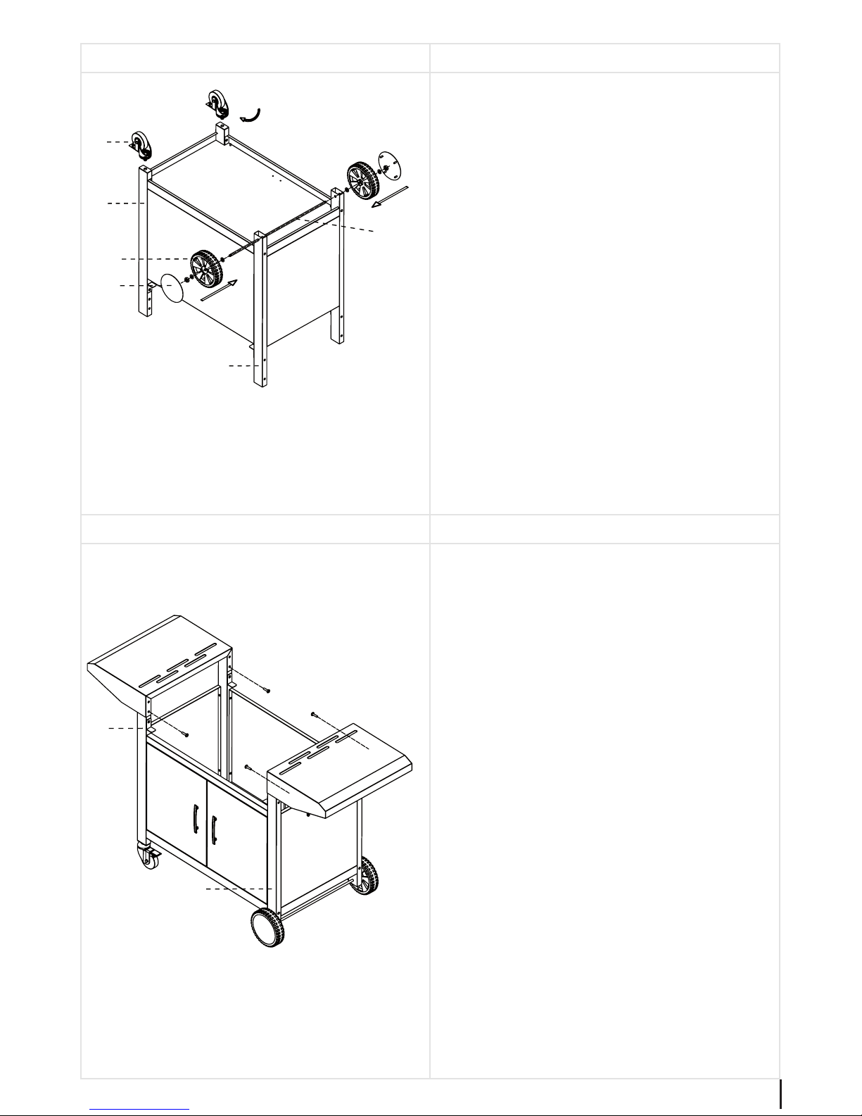
Assembly step 6
• Turn the frame around so that the doors (14) face
towards the rear. Assemble the two rollers (17) to
the left wheel legs (10). Insert the wheel axle (19)
through the upper hole in the right wheel legs (10).
Attach a wheel (20) to both ends of the wheel axle
(19) using a Ø8 washer and M8 nut. Then press the
cover caps (21) onto the wheels (20).
• Then check to make sure that the wheels (20) and rollers (21) are functioning properly.
Assembly step 7
• Position the side racks (7) on the left and right wheel
legs (10) and secure these in place using M6x10 bolts.
17
10
10
20
21
19
10
10
7
7
Page 16
16
GRILLCHEF
Assembly step 8
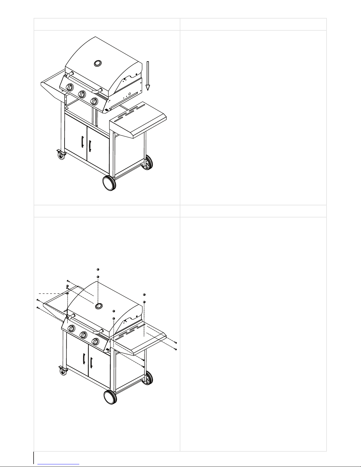
Place the grill unit (6) on the cart between the side
racks (7).
Assembly step 9
Screw both sides using M6x70 bolts and 8 x Ø6 spacers
(9).
6
7
7
9
Page 17
17
GRILLCHEF
Assembly step 10
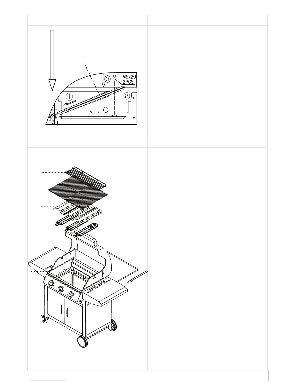
• Insert the apertures for the three burners (5) into the
respective ame regulators and screw the burners (5)
to the base of the grill unit (6) using M5x20 bolts.
• Make sure that you adhere to the
points in the illustration.
Assembly step 11
• Place the three ame covers (4) into
the recesses so that the middle triangular edges are pointing upwards.
• Place the grill (3) on top.
• Insert the warming rack (2) into
the guides on the cover.
• Insert the fat collection tray (8) into
the grill unit (6) from the rear.
5
2
6
3
4
8
Page 18

18
GRILLCHEF
Connecting and disconnecting the gas cylinder
Parts and tools needed
• 17 mm spanner (open-ended spanner SW 17)
• Gas cylinder
A common camping gas cylinder with a ll weight of 3, 5 or 11 kg (e.g. grey camping propane gas cylinder). These are
available at DIY shops or liquid gas suppliers.
• Pressure regulator
Preset and
-approved pressure regulator, max. 1.5 kg/h, operating pressure 28-30 mbar at butane, 37 mbar at pro-
pane, suitable for the gas cylinder used. This type of pressure reducer is also available from your local dealer.
• Leak detector
You can locate any leaks in the gas system using a leak detector. This can be purchased at DIY shops or liquid gas suppliers. Please follow the operating instructions of the leak detector.
The following part is included in delivery. It corresponds to the standards applicable in the country to which it has been
supplied by LANDMANN.
• Gas hose
-approved hose of sucient length, allowing installation without any kinks.
Connecting the Gas Cylinder
Danger "Ignition of escaping gas"
Liquid gas is highly ammable and explosive.
Possible consequences:
• Serious personal injury or damage to property if escaping gas ignites in an environment
in which it is not controlled.
Safety precautions:
• When connecting the gas cylinder ensure that there are no sources of ignition within a
5 m radius.
• Take special care not to light any naked ames, do not smoke or switch on electric appliances (devices, lights, door bells), etc. (sparkover possible).
• If necessary, replace the hose in order to comply with the corresponding national requirements.
1. Select a suitable place to set up the cooker. Make sure that ...
– no ammable materials or substances are in close proximity to the cooker. Minimum distance to ammable mate-
rials or substances: 2m above and 1m to the side; distance to ame resistant materials or substances - min 0.25 m.
– the cooker is positioned rmly on a at, suciently large surface area. It must not be moved during operation.
Page 19
19
GRILLCHEF
G5
G1
G3
9
G2
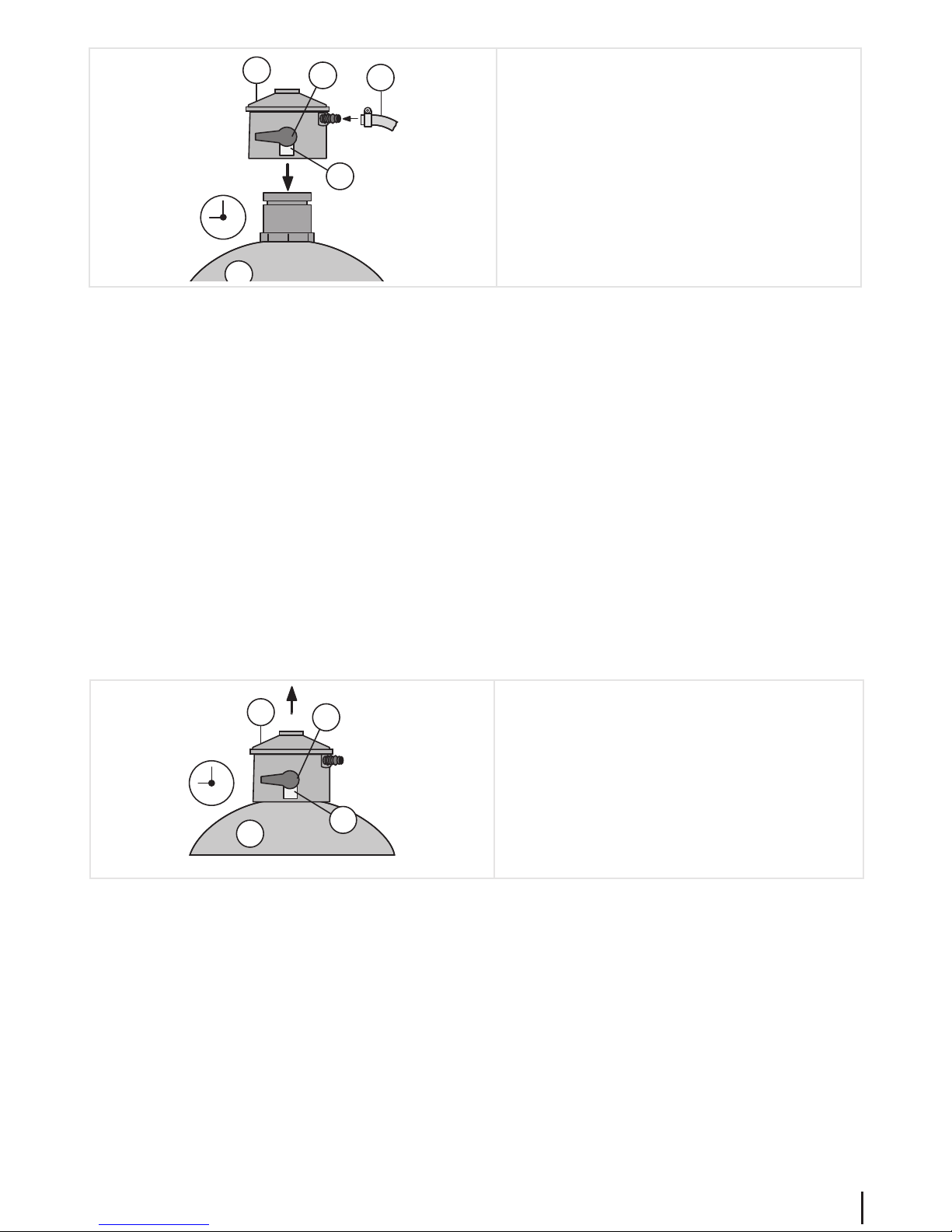
2. Position the gas cylinder next to the barbecue.
– Never lay the gas cylinder on its side or place it
on the base shelf.
– The gas hose must not be bent or under ten-
sion.
3. Check that the gas cylinder (G3) and the pressure
reducer (G1) are in good working order.
4. Turn the control button (G2) to the 9 o'clock setting
and t the pressure reducer (G1) onto the gas cylinder valve.
5. Turn the control button (G2) to the 9 o'clock setting. Check to ensure that the pressure reducer (G1) is securely on the gas
cylinder (G3).
6. Check the connection between the pressure reducer (G1) and the gas hose (G4) and the gas hose (G4) to the setting
device (19) to ensure they are secure.
7. Open the cylinder vale by pulling the red safety catch on the control button (G2) forwards a little and by turning the
control button to the 12 o'clock setting. Use a standard leak detector to ensure that all connections are tight.
Please observe the instructions for the leak detection agent!
– Never check for leaks using a naked ame. Listening for leaks is not a reliable method of detection either.
– If the connection is not sealed immediately close the bottle valve (turn control button (G2) to 9 o'clock setting) and
tighten the connection or replace the leaking part. Repeat the leak test.
8. If you do not wish to use the barbecue immediately, close the cylinder valve: turn control button (G2) to the 9 o'clock
setting.
Shut o Gas Cylinder
G1
G3
9
G2
G4
1. Close the cylinder valve: turn control button (G2) to a
9 o'clock position).
2. Pull the red safety leverl on the control button (G2)
forwards a little, turn the control button t(G2) to a
9 o'clock setting and pull the pressure reducer (G1)
from the gas cylinder valve.
3. Store the pressure reducer (G1) with the gas hose (G4) underneath the barbecue. Make sure that the gas hose is not
kinked or twisted in any way.
4. Storing the gas cylinder correctly:
– Fit the gas cylinder valve with a cap nut and safety cap.
– Do not store the gas cylinder in rooms below ground level, or in or near stairways, hallways or passages and tho-
roughfares between buildings.
– Always store gas cylinders upright, even if they are empty!
Page 20
20
GRILLCHEF
Fitting the hose connection
(if exchanging)
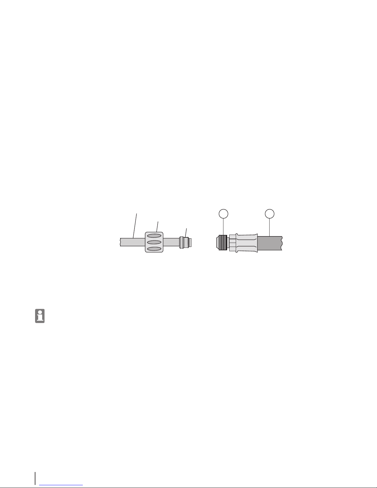
Release the old connection hose using two at spanners (14 and 17 mm). Secure the new hose connection to the connection
hose on the appliance as follows:
1. Dismantle the cutting ring connection into the following parts:
– Coupling nut
– Cutting ring
– Gas hose (G7) with locking thread (G8)
2. Push the coupling nut approx. 20 – 30 mm back onto the connection hose for the cooker.
3. Guide the cutting ring, advancing with the greater end, onto the connection hose of the gas cooker, so that the distance
between the end of the hose and the cutting ring is greater than 2 mm.
4. Guide the gas hose (G7) with the locking thread (G8) over the end of the connection hose. Screw the coupling nut and
the locking thread (G8) very tightly together using two fork keys (14 & 17 mm). The cutting ring cuts onto the connection hose of the burner so tightly that it cannot be manually removed.
connection hose of the burner
coupling nut
cutting ring
G7
G8
Operation
Starting up the burner
Before using, wash the roasting tray (2) thoroughly with warm soapy water and allow both to dry well. Then apply
cooking oil to the top side of both parts. This will prevent the cooked food from sticking to the roasting tray.
1. Check to ensure that ....
– no ammable materials or substances are in close proximity to the cooker. Minimum distance to ammable mate-
rials or substances: 2m above and 1m to the side; distance to ame resistant materials or substances - min 0.25 m.
– the cooker is positioned rmly on a at, suciently large surface area. It must not be moved during operation.
2. Check to ensure that ....
– the burner is fully assembled and has no obvious defects.
– the roasting tray (2) is inserted.
Page 21
21
GRILLCHEF
Switching o the barbecue
1. Close the cylinder valve on the gas cylinder (turn G1 clockwise).
2. Turn the ame regulator (B) to "•" (o).
3. Wait until all of the parts have cooled down and then clean any soiled components.
4. Close the lid (1).
5. If the barbecue is not going to be used for a prolonged period:
– Disconnect the gas cylinder (see chapter "Disconnecting the gas cylinder").
– Store the barbecue in a dry place.
G1
G3
9
G2
G4
3. Open the cylinder valve by pulling the red safety
catch on the control button (G2) forwards a little and
turning the control button to the 12 o'clock setting.
4. Check to make sure that the gas system is leak-proof.
If not, immediately turn the control button (G2) to
the 9 o'clock setting.
Caution: Do not lean over the cooker during steps 7 and 8. Keep a safe distance.
5. Press and turn the left ame regulator (B) to the "large ame" setting and keep it depressed.
6. If necessary, press the piezo igniter (A) repeatedly until the burner ignites.
7. Wait for a few seconds and then release the ame regulator (B).
If the ame goes out, turn the left ame regulator (B) to "•" (o), wait 3 minutes and repeat steps 6 to 8.
8. Press and turn the middle ame regulator (B) to "large ame" and keep it depressed until the middle of the burner
ignites.
9. Press and turn the right ame regulator (B) to "large ame" and keep it depressed until the right side of the burner
ignites.
10. Allow the burner to heat up at full power.
The rst time it is used, the burner should be heated at full power without any food for approximately 20 minutes to
allow the food-safe coating to harden (as is the case with any oven).
11. When the burner has heated up suciently turn the ame regulator (B) to the desired setting (size of ame).
12. You can now place the food on the roasting tray (2). We recommend that you wear barbecue gloves or similar for protection against the heat.
Page 22

22
GRILLCHEF
Cleaning
Grill
To ensure your barbecue serves you well for many years to come, it should be cleaned after each use with washing-up liquid,
a brush and a cloth - ensure that all parts have cooled down rst. This is much easier than cleaning it at a later stage when
the dirt has dried.
Caution "Spark plug on burner can be bent"
The spark plug on the burner can be bent or may snap o during cleaning.
Possible consequences:
• Burner no longer lights.
Safety measures:
• Take special care when cleaning the area around the burner.
Gas system
If necessary, the gas outlet nozzle on the adjusting element (underneath the front panel) can be cleaned with a needle. All
other parts through which gas is passed may only be cleaned by an expert.
Never dismantle the adjusting element!
Page 23

23
GRILLCHEF
Maintenance
The barbecue is maintenance free. Nevertheless, you should check it at regular intervals. The intervals depend on how often
the barbecue is used and the environmental conditions to which it is exposed.
Barbecue
• Check to ensure that all parts of the barbecue are present and assembled (visual check).
• Check to ensure that all connections are present and are securely fastened. Tighten if necessary.
Gas system
The gas system needs to be checked every time a gas cylinder is connected (see chapter "Connecting and disconnecting the
gas cylinder").
If necessary, replace the hose in order to comply with the corresponding national requirements.
Environmental information and disposal measures
Residual substances
DANGER: Risk of re when disposing of the hot residual substance
Only dispose of the residual substances when they have fully cooled down and only then
in the designated metal containers. Observe the local regulations.
Barbecue
Pay attention to cleanliness when handling the barbecue.
To dispose of the barbecue properly, disassemble it into its individual parts. Recycle the metal and plastic components.
Observe the local regulations.
Page 24

24
GRILLCHEF
Troubleshooting
If there is a fault despite due care, this chapter may help you to resolve the malfunction.
Malfunction Cause Remedy
There is a smell of gas Leak in the gas system 1. Close the cylinder valve immediate-
ly (turn G1 clockwise)
2. Prevent any ame or spark formation (do not switch on any electrical
appliances)
3. Tighten all connections of the gas
system
4. Check all components of the gas
system for external damage; replace
defective parts with original spare
parts
5. Check for leaks using a leak detector
Burner does not light Gas cylinder is empty Replace the gas cylinder
Cylinder valve is closed Turn the cylinder valve (G1) anti-clock-
wise
Nozzles of the adjusting element
(underneath the front panel) are not
inserted into the burner hoses
Conduct a visual check, if necessary align
the nozzles and connection hoses
The igniter cable is not connected to
the Piezo igniter (A)
Conduct a visual test, connect if necessary
Distance between the spark plug
and gas outlets on the burner (5) is
incorrect
Visual inspection; correct if necessary
Nozzle on adjusting element (underneath front panel) is blocked.
Remove the front panel and clean the
nozzle of the adjusting element using a
pin
Other gas system blocked The gas system should be cleaned by a
specialist
Temperature on grill too low Pre-heating time too short Close lid (1) and set ame regulator to
max. setting
Gas outlets on the burner (5) are
blocked
Remove blockages from burner
Page 25

25
GRILLCHEF
Malfunction Cause Remedy
Popping or bubbling noise Flashback caused by blockages in the
burner.
1. Close the cylinder valve immediately (turn G1 clockwise)
2. Wait 3 minutes and then switch the
barbecue back on
3. If the malfunction reoccurs, disassemble and clean the burner
Page 26
26
GRILLCHEF
(Technical regulations for liqueed petroleum gas (TRF); appendix A)
Instructions for using liquid gas cylinders
Operating instructions for liquid gas cylinder systems
(other than propellant gas cylinders and propellant gas cylinder systems)
1. Properties of liquid gas
Liquid gas (propane, butane and mixtures thereof ) is a highly ammable, colourless gas with a perceptible odour. It is heavier than oxygen and is ammable with low mixtures of
ambient air. Caution: uncontrolled gas can deagrate or explode.
Liquid gas is pressurised in the cylinder. Protect it from temperatures above 40°C! At higher temperatures, especially when exposed to re, there is a risk of an uncontrolled gas leak and
even to the cylinder bursting.
2. Conduct in the event of malfunctions and leaks: in the case of re:
(e.g. smell of gas, noise of escaping gas): (in buildings/vehicles) additionally:
Notify the re department % 112!
Close the cylinder valve immediately
(clockwise)!
Extinguish any naked ames!
Contact a specialist!
Do not smoke!
Do not actuate any electrical
switches!
Do not use the telephone!
Open windows and doors!
Transfer any leaking cylinders outside immediately!
Evacuate the building/vehicle!
Point out the presence of liquid gas cylinders!
If possible, remove cylinders from any area
that is susceptible to re or cool with water if
necessary.
3. Operation of liquid gas cylinder systems
➱ Liquid gas cylinder systems should only be installed, commissioned, modied and checked by specialised companies.
➱ Liquid gas cylinder systems should only be installed in the commercial sector by trained personnel and checked by an appropriately qualied person or, when dealing with certain
cylinder systems, by a person assigned by the contractor (accident prevention regulations (BGV D 34).
➱ The cylinder must be set in an upright position. Cylinders positioned on their side pose a threat of deagration.
➱ The operating instructions provided by the manufacturer of the liquid gas appliance are to be observed carefully by the user for operation and, if necessary, for troubleshooting
measures. Prior to the initial operation, or after making a modication, the operator of a liquid gas cylinder system must be assured of its orderly condition through examination and
certication by a specialised company (commercial systems are to be addressed by a specialised person responsible for the respective commercial sector). The certicates from the
examinations are to be kept by the operator.
➱ If the system is not going to be used for a prolonged period the valves are to be closed; when doing this start from the device shut-o valve towards the cylinder valve. When star ting
up the system again the valves are to be opened; when doing this start from the cylinder valve towards the device shut-o valve.
➱ Naked ames and smoking are prohibited in areas where large cylinders are stored and in close proximity to large cylinder systems. The ventilation openings of the installation
area and/or the cylinder cabinet must be kept free.
Warning signs must be applied.
➱ The operator is prohibited from siphoning liquid gas!
4. Changing the cylinder
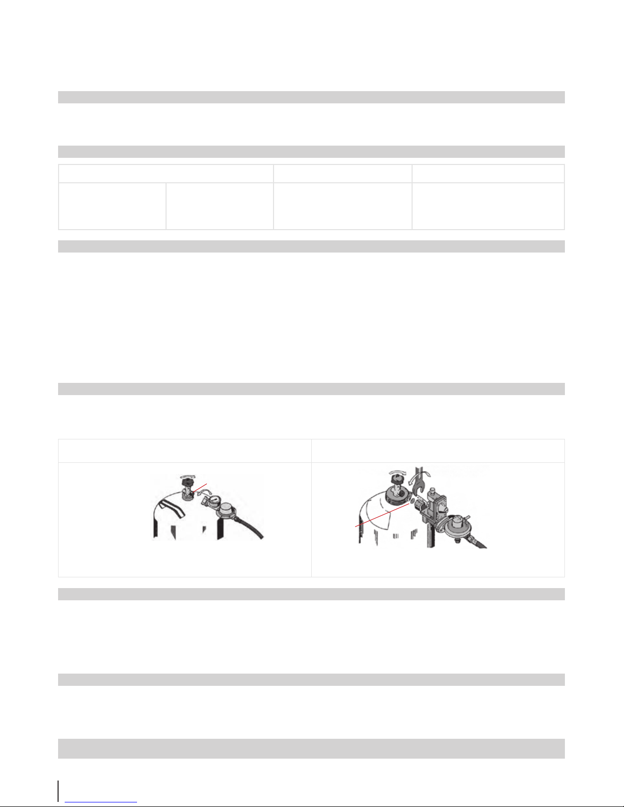
➱ When changing the cylinder only loosen the regulator connection after the cylinder valve has been fully closed (clockwise). The pressure regulator must be connected and well
sealed. Pay attention to the existing sealing ring (see diagram) Note left-hand thread! Every time the cylinder is changed the seal of the regulator connection must be tested
using foaming agents (e.g. soapy water).
➱ For multi-cylinder systems: Close the shut-o valve of the container connecting line; set switch to full cylinders.
Regulator connection small cylinder
(5 and 11 kg nominal capacity)
Regulator connection small cylinder
(33 kg nominal capacity)
Flaschenventil zu
Regler mit Schraubenschlüssel
festziehen (Linksgewinde)
Dichtring (Aluminium
oder Kunststo auf
der Reglerseite
Flaschenventil zu
Regler mit Schraubenschlüssel
festziehen (Linksgewinde)
Dichtring (Aluminium
oder Kunststo auf
der Reglerseite
5. Safety monitoring of liquid gas cylinder systems
Liquid gas cylinder systems are to be examined on a recurring basis. The examinations are to be initiated by the operator:
➱ Fixed systems in buildings with cylinders up to 11 kg nominal capacity: ...................................................................................... every 5 years by a specialised company
➱ Fixed systems in buildings with cylinders between 22 and 33 kg nominal capacity: ....................................................................every 10 years by a specialised company
➱ In accordance with accident prevention regulations BGV D 34 for commercial areas (depending on the type of system): ............ every 4 years / every 2 years / annually
➱ Systems in vehicles in the private and commercial sector: ............................................................................................................ever y 2 years
➱ Systems on boats in the private sector:.........................................................................................................................................every 2 years
Components of the system that are subject to wear (e.g. regulators, hoses, etc.) are to be replaced where applicable.
6. Transport and storage
➱ To avoid damaging the valve and to prevent gas leaks full and empty liquid gas cylinders should only be transported and stored with a closed and protected valve (wear nut and cap).
➱ When transporting in vehicles it must be ensured that there is adequate ventilation in the storage area. The cylinders must be secured from shifting during transport.
➱ The cylinders, even if they are empty, should only be stored upright in well-ventilated areas; they should not be stored below ground level (e.g. basements, shafts, etc.), in stairwells,
corridors, passageways, near emergency exits, escape routes and passages between buildings or in their immediate vicinity. No more than two small cylinders should be stored in a
home - and only then in separate rooms (not bedrooms).
Any use of energy involves a risk of danger.
Therefore please observe these user/operating instructions!
Cylinder valve closed
Soft sealing ring in the cylinder valve
Screw the regulator by hand
(left-hand thread)
Cylinder valve closed
Tighten the regulator with a
spanner (left-hand thread)
Sealing ring (aluminium or plastic) on the
regulator side
Page 27
27
GRILLCHEF
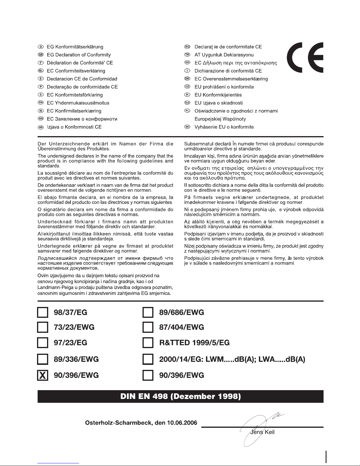
Declaration of conformity
Page 28

28
GRILLCHEF
LANDMANN® Ltd.
Unit 1, Ryelands Business Centre,
Ryelands Lane, Elmley Lovett, Worcs, WR9 0PT,
United Kingdom
e-mail: [email protected]
internet: www.landmann.co.uk
Hotline
Monday to Thursday 9am to 5pm,
Friday, 9am to 4pm.
Barbecue Helpline **44 - 12 99 - 25 17 47,
Sales Oce fax: **44 - 12 99 - 25 32 13
 Loading...