


DESYS srl
BORING MACHINE Mod. GF 21G
GF 27G
GF 35G
SPARE PARTS INSTRUCTIONS
GRIGGIO S.p.A.
WOODWORKING MACHINERY
Via Ca’ Brion, 40 - 35011 Reschigliano (PD) ITALY
Tel. 049/9200920 Fax 049/9201433
http://www.griggio.com E-Mail:info@griggio.com


GRIGGIO S.p.A.
WOODWORKING MACHINERY
MODEL
BORING MACHINES
GF21 spindles
GF27 spindles
GF35 spindles
MACHINE N°
YEAR OF MANUFACTURE
GRIGGIO S.p.A. WOODWORKING MACHINERY
Via Ca’ Brion, 40 - Reschigliano (PD) ITALY
Tel. 049. .9200920
Fax 049. .9201433
C.A.P. 35011
http://www.griggio.com
E-Mail:info@griggio.com


GRIGGIO S.p.A.
WOODWORKING MACHINERY
1
WE WOULD LIKE TO THANK YOU FOR
HAVING CHOSEN ONE OF OUR PRODUCTS
This manual contains all information, advice and warnings that our technicians deemed
essential to operate the machine properly.
It also contains routine maintenance rules, so that your machine will always be kept in
perfect working order.
We advise you to read this manual entirely before operating the machine for the first
time.

2
GRIGGIO S.p.A.
WOODWORKING MACHINERY
INDICE
1. CONFORMITY CERTIFICATE ......................................................................................... 4
2. SAFETY AND GENERAL SAFETY INFORMATION ........................................................ 4
2.1 USAGE AND MAINTENANCE ADVICE ................................................................. 4
2.2 MACHINE IDENTIFICATION ................................................................................. 4
3. OPERATIVE NOTES ....................................................................................................... 5
4. DESCRIPTION OF THE MACHINE .................................................................................5
4.1 APPLICABLE TOOLS ............................................................................................5
4.2 MACHINE PARTS ................................................................................................. 6
5. SUPPLIED EQUIPMENT ................................................................................................. 6
6. SAFETY DEVICES .......................................................................................................... 7
7. INDIVIDUAL SAFETY DEVICES ...................................................................................... 8
8. TECHNICAL SPECIFICATIONS ......................................................................................8
8.1 WEIGHT ................................................................................................................8
8.2 OVERALL SIZE ..................................................................................................... 8
8.3 MAX. SIZE OF PIECE TO BE BORED .................................................................. 8
8.4 ELECTRICAL CHARACTERISTICS ....................................................................... 8
8.5 TABLE SIZE .......................................................................................................... 9
8.6 INTERAXIAL DISTANCE BETWEEN SPINDLES .................................................. 9
8.7 NUMBER OF SPINDLES ....................................................................................... 9
8.8 INTERAXIAL DISTANCE BETWEEN FIRST & LAST SPINDLE ............................ 9
8.9 SPINDLE REVOLUTIONS ..................................................................................... 9
8.10 MAX. BORING DEPTH .......................................................................................... 9
8.11 WORKING PRESSURE ......................................................................................... 9
8.12 AIR CONSUMPTION ............................................................................................. 9
9. AUTHORISED USAGE .................................................................................................... 9
9.1 MATERIALS .......................................................................................................... 9
9.2 IMPROPER USAGE .............................................................................................. 9
10. SHIPMENT .................................................................................................................... 10
11. MACHINE SIZE .............................................................................................................10
12. INSTALLATION .............................................................................................................11
13. WORKING AREA ........................................................................................................... 11
14. ASSEMBLY AND PRELIMINARY STEPS TO OPERATE THE MACHINE
FOR THE FIRST TIME ................................................................................................... 12
15. CONNECTING THE MACHINE TO EXTERNAL ENERGY SOURCES .......................... 12
15.1 CONNECTION TO POWER SUPPLY MAINS .....................................................12
15.2 PNEUMATIC CONNECTION ............................................................................... 12
15.3 CONTROL PANEL ..............................................................................................13
16. CHECKS AND ADJUSTMENTS .................................................................................... 14
16.1. DISCONNECTIONG PROCEDURE ....................................................................14
16.2. PREVENTION CHECKS ...................................................................................... 14
16.3 BORING DEPTH ................................................................................................. 14
16.4 HOW TO ADJUST HEAD PARALLELISM ........................................................... 15
16.5 HOW TO POSITION SPINDLEHEAD HORIZONTALLY AND VERTICALLY……..15
16.6 HOW TO USE REFERENCE STOPS FOR STANDARD 0°-90°WOODWORKING …16
16.7 HOW TO USE EXTENSION FENCE .................................................................... 16

GRIGGIO S.p.A.
WOODWORKING MACHINERY
16.8 HOW TO USE REFERENCE PIN TO BORE SERIES OF HOLES ON LARGE
PIECES (OPTIONAL)…………………………………………………………………...17
16.9 HOW TO USE TRIANGULAR FENCE FOR 45° BORING AND SPLINE
(OPTIONAL)………………………………………………………………...………18
16.10 WOODWORKING EXAMPLES…………………………………………………….,….19
17. HOW TO START THE MACHINE .................................................................................. 21
17.1 WORKING CYCLE .............................................................................................. 21
18. MAINTENANCE ............................................................................................................ 21
18.1 MACHINE CLEANING (DAILY) ........................................................................... 21
18.2 RAILS CLEANING (WEEKLY) ............................................................................. 21
18.3 KINEMATICS CLEANING AND CHECKS (MONTHLY) ...................................... 21
18.4 EXTRAORDINARY MAINTENANCE .................................................................. 21
19.COMMON FAILURES – CAUSES AND SOLUTIONS .................................................... 22
19.1DRILLS ARE NOT TURNING……………………………………………………………..22
19.2 ENGINE IS RUNNING BUT DRILLS ARE NOT TURNING ................................. 22
19.3 BORED HOLE IS NOT PRECISE ....................................................................... 22
20. FAILURES THAT MIGHT OCCUR DURING MACHINE WORKING CYCLE…………….23
20.1 DRILLS LEAVING SCORCH MARKS ................................................................. 23
20.2BORED PIECES ARE NOT SET AT A 90° ANGLE TO TABLE………………………23
20.3 HEAD CANNOT ROTATE PROPERLY ............................................................... 23
20.4 HOLD DOWN CLAMPS CANNOT CLAMP WOOD PIECE ................................. 23
21 A. NOISE LEVEL ............................................................................................................ 23
21 B. DUST EMISSION ....................................................................................................... 23
22. PNEUMATIC SCHEME .............................................................................................. 24
23 A. ELECTRICAL SCHEME FOR GF21, GF27 (WITH ONE ENGINE) ............................. 24
23 B. ELECTRICAL SCHEME FOR GF 35 (WITH TWO ENGINES) ................................... 25
24. MACHINE IS PUT OUT OF COMMISSION ................................................................ 26
25. GUARANTEE CERTIFICATE ..................................................................................... 27
26. SPARE PARTS CATALOGUE…………………………………………………………...….29
3
4
GRIGGIO S.p.A.
WOODWORKING MACHINERY
1. CONFORMITY STATEMENT
Griggio S.p.A. declares that this Boring machine has been manufactured accurately, by using the best
techniques available to manufacture a quality product. We also declare that our boring machine com-
plies with EEC 89/392 Machines Guideline, as well as with the following standards:
EN 292/1
EN 292/2
EN 60240
EN 60240/1
EN 73/23 CE
IEC 408
The machine is hence commercialised with conformity mark:
GRIGGIO S.p.A.
Via Cà Brion,40 - 35011
Reschigliano (PD) ITALY
The President
2. SAFETY AND GENERAL SAFETY INFORMATION
2.1 USAGE AND MAINTENANCE ADVICE
In this manual we have considered all routine maintenance operations.
We advise you not to carry out any other working, repair or intervention than the ones envisaged in this
manual.
We suggest that you keep this manual with care and in a location where it can easily be found and consulted by the operator.
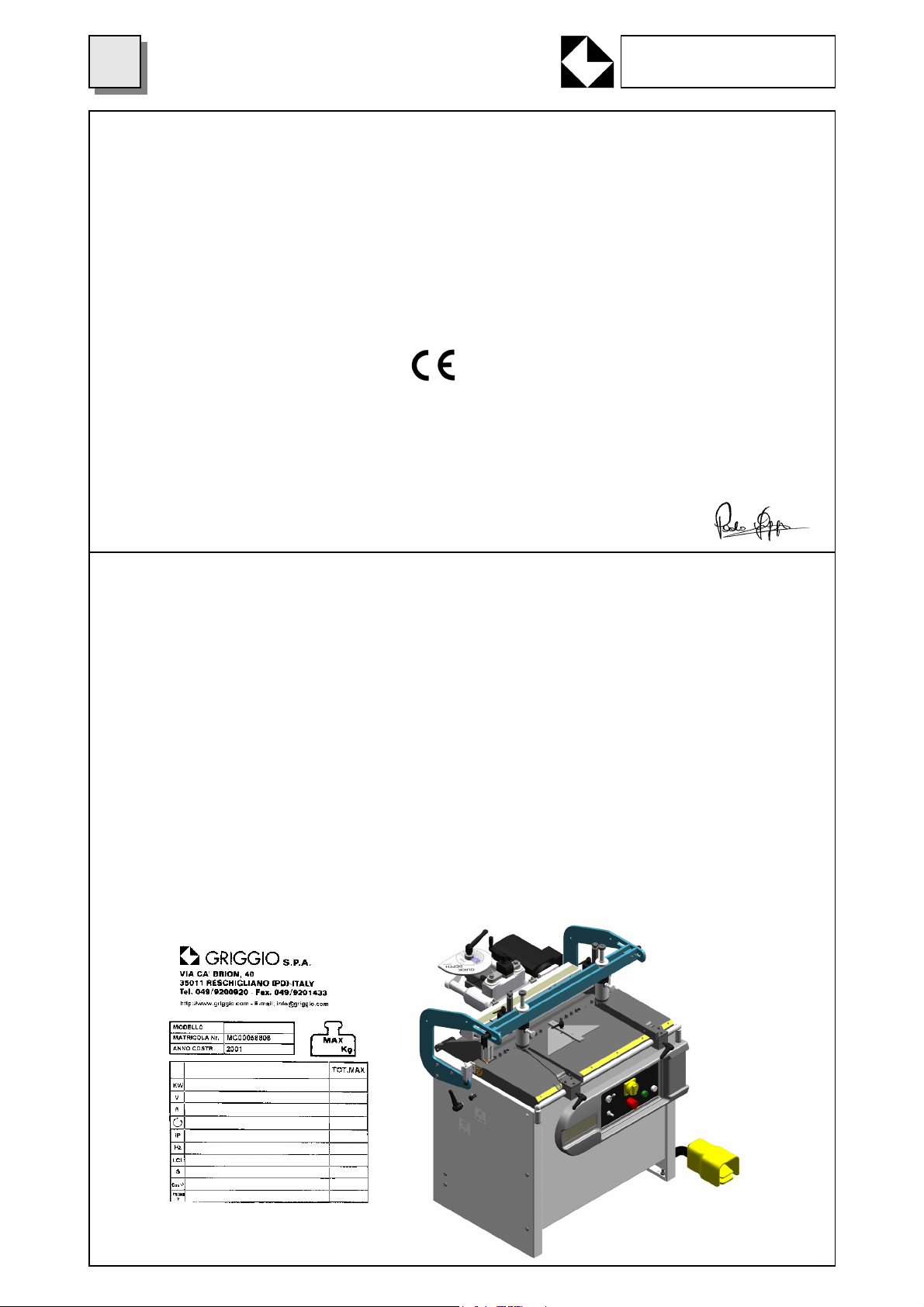
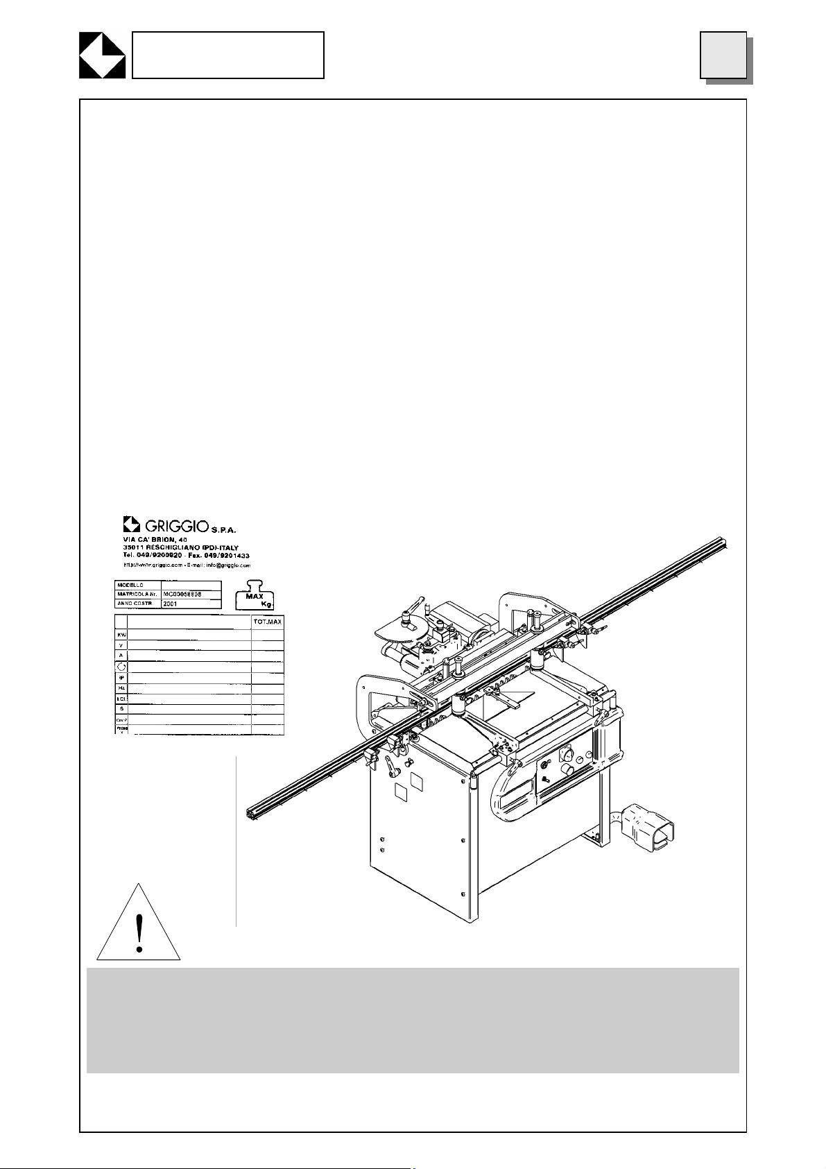
2.2 MACHINE IDENTIFICATION
The machine can be identified by means of the information written on the plate located in the front of the
machine on the left-hand side. When spare parts are ordered or advice is required to operate the machine or to carry out maintenance operations, always indicate the machine’s model number written on
the plate, as well as voltage and nationality.
It is absolutely forbidden to remove the plate or to change the information written on it.
On the Boring machine described in this manual, the following plate has been attached:

GRIGGIO S.p.A.
WOODWORKING MACHINERY
3. OPERATIVE NOTES
WOODWORKING MACHINES CAN BE DANGEROUS
1) To operate the machine safely and correctly, follow the indications contained in this manual care
fully and scrupulously.
2) The machine will have to be operated only by personnel who is both qualified and over 18. People
responsible for safety should make sure that the machine operator has read and fully understood all the
information contained in this manual.
3) Maintenance interventions must be carried out only by personnel who is both qualified and of age.
4) Personnel responsible for periodical and extraordinary servicing must have a good knowledge of
mechanics and electronics.
5) Keep away from any moving part in the machine.
Never touch the spindles and /or the drills when the machine is operational.
6) Never superimpose wood pieces to be worked. Always bore one piece at a time, after having adjusted the machine correctly.
5
REMOVING OR TAMPERING WITH SAFETY DEVICES MAY CAUSE SERIOUS ACCIDENTS. IT IS
FORBIDDEN TO REMOVE, EXCLUDE OR MODIFY SUCH DEVICES. PERIODICAL CHECKS
MUST BE CARRRIED OUT TO MAKE SURE THAT SAFETY DEVICES ARE ALWAYS IN GOOD
WORKING ORDER. ANY DEFECT OR POSSIBLE PROBLEM IS TO BE DEALT WITH IMMEDI-
ATELY.
4. DESCRIPTION OF THE MACHINE
Our Boring Machines have been manufactured to make a series of holes at a fixed 32-mm distance between centres on wooden pieces (with maximum precision).
The head has its fulcrum on the machine table and it can be tilted until a 90-degree angle. The pieces to
be bored are fed by the operator, who places them on the machine table. The operator will carry out the
required adjustments by pressing the control pedal before locking the pieces into place with the relevant
hold down clamps and starting boring operations.
The following parts make up the machine:
• A steel frame structure
• Spindlehead unit with transmission and drill spindles with quick-change seat (standard).
• Hold down clamps unit to clamp the piece to be cut in a vertical position.
• Pneumatic system for head positioning and head feed.
• Back stops so as to obtain the same vertical and horizontal boring distance
• Crank mechanism to adjust spindles height, equipped with mechanical counter and quick-depth de-
vice to adjust hole depth from 0 mm to 100 mm.
4.1 APPLICABLE TOOLS
Quick-change spindle drills with a 10mm-diameter shank L=20mm.
Drills up to 40mm-diametre outside the rack can be used; 100 mm maximum working length (attachment
is not taken into account).

6
GRIGGIO S.p.A.
WOODWORKING MACHINERY
4.2 MACHINE PARTS
1) Electric power line light
2) Switch to make the engine operational
3) Emergency pushbutton
4) Machine clamping
5) Lever-operated valve for head overturning piston.
6) Piston adjustment and drills feed speed
7) 45°Block pin
8) Back stops
9) Tilting degree dial for spindlehead
10) Fast-positioning safety hold down clamps
11) Clamping handle for hold down clamps rail
12) Table limiters
13) Clamping handle for limiters rails
14) Limiters exclusion device
15) Electric control board
16) Rack rotation clamping handle
17) Control handle for drills height from table
18) Drills depth adjustment for piece to be bored
19) Reference pin to repeat sets of holes (optional)
20) Lubrication-filter-regulator air unit
21) Drills feed cylinder
22) Spindlehead
23) Engine
24) Pneumatic control pedal
25) Electrical main switch
5. SUPPLIED EQUIPMENT
The machine comes with the following equipment to adjust the machine itself:
- 45-degree head position clamp
- Protractor scale to position the boring head
- Quick-positioning safety hold down clamps
- 4 T.E. wrenches sizes 6/7, 10/11, 12/13, 16/17.
- 7 hexagon ring wrenches sizes 2.5-3-4-5-6-8-10
- 5 quick-change bushes for cylindrical-shank drills 10 mm in diameter
- 3000mm extension fence with millimetrical scale and 4 oscillating stops
The following equipment is available on request:
- 45° Triangle for frame construction
- Central spline for 90° frames
- An additional extension fence with millimetrical scale (3000 mm max)
- Additional oscillating stops for extension fence
- Reference pin for line boring (2 pins maximum)
- Additional quick-change bushes for cylindrical shank drills 10 mm in diameter
GRIGGIO S.p.A.
WOODWORKING MACHINERY
7
6. SAFETY PROTECTION
The main risk is due to the revolving drills. To reduce this risk to the minimum, our machines have been
equipped with the following safety devices:
1) Emergency Pushbutton
It is located on the control board in the front part of the machine. When it is pressed, all machine movements are halted immediately.
2) Set of Plates
They contain an accurate description of safety precautions and indications on how to operate the machine and make it possible to identify the machine parts. One of these plates contains the identification
data and the serial number of the machine itself.
3) Side Protections
They prevent the operator from inserting his/her hands accidentally into the machine when the spindlehead is moving.
4) Safety hold down clamps (patented)
They remain either on the machine table surface or on the piece to be worked that has already been positioned, thus preventing the operator from accidentally placing his hands under one of them.
5) EL Safety Device
No-return coil to prevent accidental starting of the machine.
CAUTION SYMBOL: ALL OPERATIONS MARKED WITH THIS SYMBOL ARE
DANGEROUS FOR THE OPERATOR. AS A RESULT THE OPERATOR MUST
PAY THE GREATEST ATTENTION WHILE CARRYING THEM OUT.

8
GRIGGIO S.p.A.
WOODWORKING MACHINERY
7. INDIVIDUAL SAFETY DEVICES
Although safety devices used are valid, dangerous situations might occur resulting from:
- FALLING OR FLYING WOOD SPLINTERS WHILE PIECE IS BEING WORKED
- CLOTHING BEING TRAPPED IN MOVING PARTS OF THE MACHINE
- FIRE DANGERS
- ELECTRIC SHOCK DANGER
- RISK OF NOISE-RELATED DAMAGES
To prevent any risk occurring during positioning, installation, adjustment, usage, periodical and extraordinary maintenance operations, we advise you to wear:
- gloves (to handle machine parts, components and while replacing drills)
- anti-slip and anti-crush shoes
- goggles or face shields to protect against flying chips and splinters while the piece is being worked
or when the machine is being cleaned
Clothing must also be suitable to prevent
- trapping danger
- dragging danger
- crushing danger
- slipping danger
For further information and advice, please read chapter 3 “OPERATIVE NOTES”
8. TECHNICAL SPECIFICATION
8.1 WEIGHT
NET WEIGHT
Version. GF 21 320 Kg
Version. GF 27 360 Kg
Version. GF 35 444 Kg
8.2 OVERALL SIZE
Version. GF 21 1100 x 780 x 1300 mm
Version. GF 27 1200 x 780 x 1300 mm
Version. GF 35 1350 x 1040 x 1250 mm
8.3 MAXIMUM SIZE OF PIECE TO BE BORED
Version. GF 21 850 x 3000 mm
Version. GF 27 990 x 3000 mm
Version. GF 35 1308 x 3000 mm
Maximum thickness of piece to be drilled is 90 mm (all machine models)
8.4 ELECTRICAL CHARACTERISTICS
The electrical characteristics of the machines are:
- Supply voltage: 220/400 – 230/460 Volts
- Frequency: 50/60 Hz
- Number of current phases: 3
- Power: 1.5 kW (n.2 Hp) (Versions GF2132 GF2732)
2 X 1.5 kW (n.2 X 2 HP) (Version GF3532 – 2 Engines)
- Single-phase 220V (optional). For other voltage values please contact us.

GRIGGIO S.p.A.
WOODWORKING MACHINERY
8.5 TABLE SIZE
Version GF 21 900 X 380 mm
Version GF 27 1050 X 380 mm
Version GF 35 1360 X 410 mm
8.6 INTERAXIAL DISTANCE BETWEEN SPINDLES
The interaxial distance between spindles is 32 mm.
8.7 NUMBER OF SPINDLES
Version GF 21 21 spindles
Version GF 27 27 spindles
Version GF 35 35 spindles
8.8 INTERAXIAL DISTANCE BETWEEN FIRST AND LAST SPINDLE
Version GF 21 640 mm
Version GF 27 832 mm
Version GF 35 1088 mm
8.9 SPINDLE REVOLUTIONS
Spindles revolutions are …2800 r.p.m. at 50 Hz
Spindles revolutions are …3300 r.p.m. at 60 Hz
8.10 MAXIMUM BORING DEPTH
Maximum boring depth is …100 mm.
8.11 WORKING PRESSURE
Working pressure is … 6/7 bar
8.12 AIR CONSUMPTION
Air consumption is …10L/Cycle
9
9. AUTHORISED USAGE
9.1 MATERIALS
This boring machine has been designed and manufactured to bore holes in the following materials:
- heart-wood
- M.D.F.
- Chip-wood boards, laminated wood, ennobled wood etc.
Maximum board thickness is 82 mm with maximum size indicated in paragraph 8.3
Other materials than the ones indicated above can be worked only after having received written approval by machine manufacturer. In particular it is forbidden to work materials containing toxic substances or substances that are hazardous for operator’s health and safety. It is also forbidden to bore
metals or substances that might impair the machine good performance of might cause fire or explosions.
- Any modification to the machine is forbidden without the written approval by the machine manufacturer.
- It is forbidden to tamper with the machine safety devices
9.2 IMPROPER USAGE
Any operation that does not comply with the indications given in this manual is to be regarded as improper usage.
Moreover:
WE ADVISE YOU NOT TO: lay tools against or on the machine during machine installation, usage or
maintenance operations for any reason whatsoever.
WE ADVISE YOU NOT TO: get on the machine or on any of its parts.
The manufacturer cannot be held responsible for any damage caused to people, animals, or objects
resulting from improper usage of the machine.
10
GRIGGIO S.p.A.
WOODWORKING MACHINERY
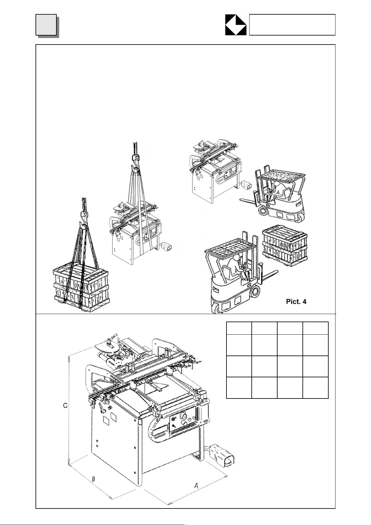
10. SHIPMENT
This boring machine is packed in a wooden box and/or in a cardboard and nylon box.
Machine handling is possible with:
- fork-lift trucks
- bridge cranes
- pallet trucks
Weight is indicated in paragraph 8.1 and hoisting points can be seen in the picture below. When the machine is handled it is necessary to make sure that the surrounding area is free from obstacles. If the machine is stored, it must be kept in a dry place, protected from rain, snow or dampness. During all handling operations, we advise you to pay great attention in order to prevent any damage to people, things
or to the machine itself.
11. MACHINE SIZE
Mod.
GF21
Mod.
GF27
Mod.
GF35
A B C
1100 780 1300
1200 780 1300
1480 1040 1250
Pict. 5
GRIGGIO S.p.A.
WOODWORKING MACHINERY
11
12. INSTALLATION
The machine must be installed on a surface strong enough to sustain its weight so as to prevent harmful
vibrations from impairing the good performance of the machine.
To guarantee maximum machine efficiency and safety, the surface where the machine is located must
be made of well-levelled concrete. If the surface does not meet such requirements, we advise you to
make a suitable one.
Place the machine in a room, in a suitable position to be used and to be easily connected to
- power supply network
- compressed air network
- suction plant
The location where the machine will be placed must be equipped with suitable lighting to execute working or maintenance operations.
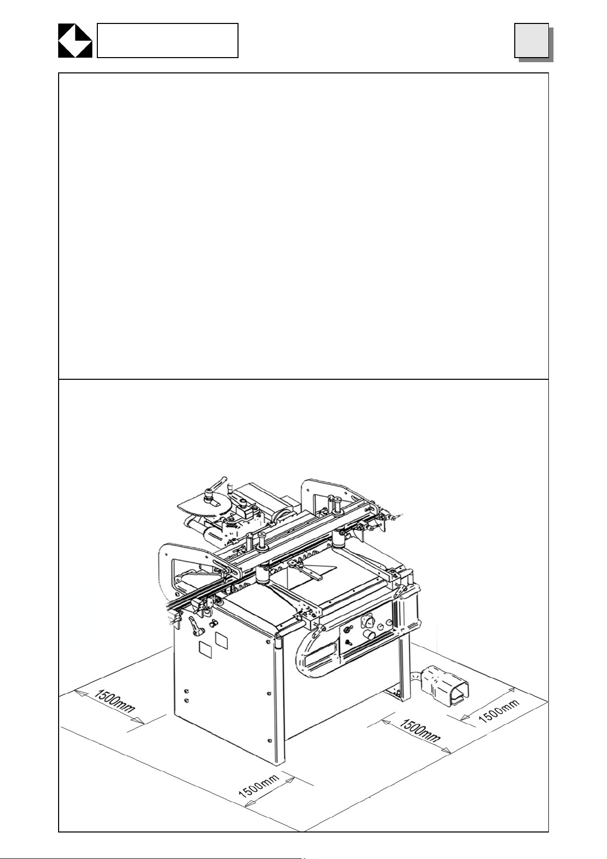
13. WORKING AREA
To be able to use the machine properly, the areas indicated in the picture below must be left free.

12
GRIGGIO S.p.A.
WOODWORKING MACHINERY
14. ASSEMBLY AND PRELIMINARY STEPS TO OPERATE THE MACHINE FOR
THE FIRST TIME
When the machine is delivered, it is partially assembled. It is therefore necessary to assemble those
pieces that are delivered disassembled for packaging reasons.
Before starting assembling operations, the purchaser must make sure that all machine parts are intact
and have not been damaged during shipment.
In particular, we advise you to check the most fragile components, such as electrical or mechanical
parts, pneumatic tubes or the machine’s safety devices.
When assembly operations are over, the machine must be cleaned by removing protective oil, so that
wood pieces do not get stained while being worked.
CAUTION: THE MACHINE IS SUPPLIED WITHOUT A SUCTION PLANT. TO KEEP DUST CONCENTRATION BELOW THE T.L.V. SET IN THE COUNTRY WHERE THE MACHINE IS LOCATED, THE
USER MUST INSTALL A SUITABLE SUCTION PLANT ACCORDING TO USAGE, MATERIAL AND
FREQUENCY OF USE.
Saw dust disposal
Saw dust and work scraps disposal is to be carried out in compliance with the regulations in force in the
country where the machine is used. We advise you to ask the relevant bodies of your country for the
relevant legislation so that you know what steps are to be taken.
15.CONNECTING THE MACHINE TO EXTERNAL ENERGY SOURCES
After assembling and installing the machine correctly, the machine has to be connected to:
- power supply mains
- compressed air system
15.1 CONNECTING THE MACHINE TO POWER SUPPLY MAINS
Engine (or Engines) voltage and frequency are indicated on the plate located on the engines.
The user’s electric installation must comply with CEI 64.8 (CENELEC HD 384, IEC 364-4-41) standards.
The electric installation must have:
- Equipotential earthing system
- Automatic protection devices installed on the machine and connected so as to guarantee that the
machine is automatically cut off from power supply in compliance with the above-mentioned standards.
Connection to the power supply is made with a three-phase plug (or with a single-phase plug according
to the board required).
Wire for the earthing system is yellow-green.
Allowed oscillation of electric voltage is +/- 10%
Connect the machine cable to the power supply mains.
Switch the machine on and make sure the machine‘s engines are revolving clockwise. Make sure that
spindles rotation matches the direction indicated on the spindlehead. (R= right L= left). If rotation direction does not match, invert connection cables to the engine.
Refer to the electrical diagrams enclosed in this manual.
15.2 PNEUMATIC CONNECTION
1) Connect the machine to the compressed air system and make sure that the connection tube is compatible with the one provided alongside the machine itself and located on the lubrication-filter-regulator
unit at the back of the machine, in the lower left-hand side.
Pressure should range between 6 and 7 bar maximum.
1) The lubrication-filter-regulator unit is made up by:
A) A filter, whose function is to purify air from dust and humidity that might damage the valves or gaskets in pneumatic cylinders.
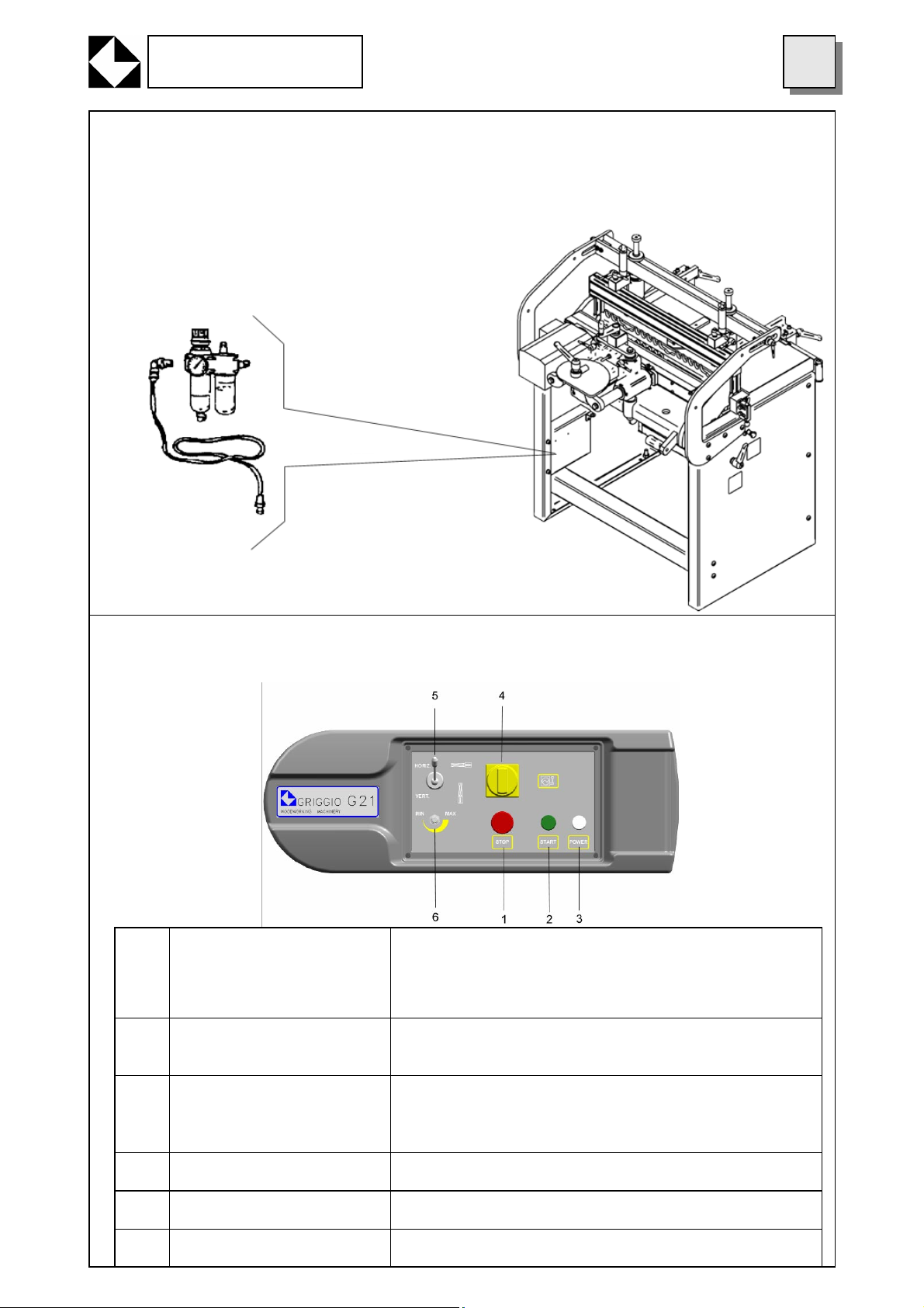
GRIGGIO S.p.A.
WOODWORKING MACHINERY
B) A regulator that adjusts compressed air working pressure by keeping this value within the abovementioned limits.
C) A lubricator that puts a determined amount of oil into the system to lubricate cylinders, valves, gaskets and moving parts.
13
15.3 CONTROL PANEL
The control panel is located on the left-hand side of the machine:
EMERGENCY PUSHBUTTON TO HALT THE ENGINE (THE BUTTON IS
1
NOT AUTOMATICALLY RELEASED)
PUSHBUTTON WITH PILOT LIGHT TO MAKE EN-
2
GINE OPERATIONAL
1 - By pressing this button all electrical functions of the machine are switched off.
2 - To switch electric functions on, turn the mushroom
pushbutton in the direction indicated by the arrows.
1 - It gets the engine ready to be started and hence it gets
the spindles ready to rotate during the working cycle.
ON/OFF POWER INDICA-
3
TOR PILOT LIGHT
MAIN SWITCH 1 - It the switch is turned on power is supplied
4
HEAD UNIT OVERTURN-
5
ING VALVE
FEED SPEED ADJUST-
6
MENT
1 - If the light is on power is available.
2 – If the light is off power is not available.
1 – If the valve is switched on the head-unit is overturned
1 – It adjusts drills boring feed speed

14
GRIGGIO S.p.A.
WOODWORKING MACHINERY
16. CHECKS AND ADJUSTMENTS
WE ADVISE YOU TO DISCONNECT THE MACHINE FROM POWER SUPPLY AND FROM THE
PNEUMATIC SYSTEM WHENEVER YOU NEED TO SERVICE THE MACHINE ITSELF OR TO REPLACE DAMAGED OR WORN PARTS. IF THIS IS THE CASE, FOLLOW THE PROCEDURES INDICATED BELOW AND PAY ATTENTION TO THE ADVICE GIVEN IN CHAPTER 6 OF THIS MANUAL.
16.1 DISCONNECTING PROCEDURE
Before carrying out any maintenance intervention on the machine, follow this procedure:
1. Make sure the machine is in a suitable position to carry out the needed intervention. After having
fastened the machine mechanically in this position, disconnect the machine from power supply and from
the pneumatic system.
2. Make sure the machine is not connected to any other energy supply and that no residual power is
left.
It is essential that this procedure is carried out by a single person only, who will then have to make the
16.2 PREVENTION CHECKS
Make sure the area surrounding the machine is neat and clean and that no working scraps are left
around, such as saw dust and wood pieces.
MAKE SURE ALL SAFETY AND PROTECTION DEVICES ARE IN PLACE, IN GOOD WORKING ORDER AND READY FOR THE OPERATIONS THAT HAVE TO BE CARRIED OUT.
16.3 BORING DEPTH
To carry out the required boring, follow these procedures:
A) Insert suitable drills in the desired position on the spindlehead.
B) Turn the handle (1) to adjust the desired distance between drills and working table with spindlehead
at a 90° angle from table surface. Drill distance is indicated in mm. on the mechanical counter (2). Turn
the handle so that the screw is stretched in the required position at the required height, so that greater
boring precision is obtained. Drill height chosen depends on wood thickness, on the position of the hole
and on the diameter of the hole itself.
C) To set boring depth follow this procedure. Once the overall length value of the drill being used has
been found on the depth selection screw (3), it is possible to set (no calculation is needed) the actual
boring depth value. By unclamping the handle (4) and by turning the depth selection screw (3) until the
desired value, the pointer (5), which is also a magnifier, will indicate the chosen depth value. Tighten the
handle before starting boring operations.
D) Usually use a scrap wood piece to test the machine settings before boring a good piece of wood.

GRIGGIO S.p.A.
WOODWORKING MACHINERY
16.4 HOW TO ADJUST HEAD PARALLELISM
To adjust head parallelism according to the working table:
- partially unscrew the screws (3) and operate alternatively on the screws (1) and screw nuts (2)
- position the drills parallel to the table
- tighten the screws very well (3)
15
16.5 HOW TO POSITION SPINDLEHEAD VERTICALLY AND HORIZONTALLY
To position the spindlehead at 90°, follow this procedure:
With spindlehead at 0°:
Unfasten the head by turning the handle (2) located on the left-hand side of the machine.
Operate on the boring head (3), by switching the lever (4) located at the front of the machine; lock the
head into position by tightening the handle (2).
To position the spindlehead at 0° do as follows:
With spindlehead at 90°:
Make sure the lever at the front of the
machine is also set at 90° and that the
pneumatic system is on (hence overturning lever must be active)
Unclamp spindlehead clamping handle
(2) on the left-hand side of the machine.
SELECT 0° POSITION WITH HEADPOSITIONING LEVER (4). ONCE THE
HEAD IS IN ITS NEW POSITION
CLAMP IT WITH THE CLAMPING HANDLE (2).
How to set Spindlehead at 45°
If the spindlehead is set at 0°:
- Make sure the head-overturning lever
(4) is also at 0° and that pneumatic pressure in the pneumatic system is correct.
- Insert lock at 45°in locking position;
- Clamp head-clamping handle (2);
- Lower head-rotating lever (4) located
in the front of the machine at 90°;
- Once the machine has been set at
45°, tighten the clamping handle until it is
clamped (2).
WARNING DANGER!
Follow the procedure described below very carefully.
!
PICT A

16
16.6 HOW TO USE REFERENCE STOPS FOR STANDARD 0°-90°WOODWORKING
Side rails and back stops are used to position the piece to be worked in a standard working cycle.
With spindlehead at 90° and spindle unit locked into position:
- Set side rails at the right distance from drills that will be used and fasten them.
- Position the hold-down cylinder (or hold-down cylinders) (3) on the table where the piece to be
worked will be located.
- Position the piece to
be bored against side limiters and use them as rails
to position the piece under
the hold down clamps and
right against the rack.
- Now position the stops
(2) over the piece to be
bored, lower stop reference block itself on the
piece, and clamp the stop
itself with the handle.
- The piece is in the right
position and it is now possible to start the working
cycle by pressing the pedal
that starts drills feed with
engine switched on (make
sure engine switch is on).
At the same time hold
down clamps will lock the
piece into position.
GRIGGIO S.p.A.
WOODWORKING MACHINERY
When the first phase is over, release the pedal to release the piece and take the bored piece out of the
machine.
Unfasten the spindlehead unit and switch the overturning lever to reposition the spindlehead at 90°.
Once the head has been repositioned and locked into position, the second phase can begin:
- Position the piece that has to be joined to one that has just been worked against the side limiter under the hold down clamp (or hold down clamps) (3) and against the back stop block.
- Once you are sure the piece has been positioned correctly, press the pedal to activate hold down
clamp lock, drills rotation and drills feed.
- Once the pedal is released, the piece will be released and the working cycle will be over.
THE TWO PIECES THAT HAVE BEEN OBTAINED (0° -90°) ARE NOW READY TO BE JOINED
16.7 HOW TO USE EXTENSION FENCE (3000 MM STANDARD)
The extension fence is used to make a set of larger holes than the ones the machine can make or to
bore large pieces. To use the extension fence you usually have to exclude side limiters completely or
partially. To position the extension fence you usually have to exclude side limiters completely or partially
and to set the spindlehead at 90°. If you use the extension fence longitudinally, we advise you to exclude side limiters completely, since it is possible to use mobile reference stops on the extension fence
itself to position the piece to be worked. (The extension fence is provided with 4 mobile stops with positioning screws, stop screw and extension fence clamping device).

GRIGGIO S.p.A.
WOODWORKING MACHINERY
LONGITUDINAL POSITION OF EXTENSION FENCE:
- Unfasten the appropriate handles and turn side limiters over to bring them out of the table, making
sure they are under the working table.
- Once the working table has been cleared, position the extension fence against the back stops and
fasten it with the apposite screws.
- After positioning the extension fence longitudinally, by means of stop screw on the fence itself, use
back stops to find boring line parallel and distance between extension fence and drills line with drills
height handle.
- Lock the fence into position and the fence is now positioned correctly. By using the mobile stops it is
now possible to bore sections or repeat set of holes on long pieces.
- Add a suitable support for the fence and the board to be bored (i.e. a stand)
17
TRANSVERSAL POSITION OF EXTENSION FENCE:
To use the extension fence transversely, you have to fasten the fence to the side limiter with the apposite screws provided.
Follow this procedure:
- Position the extension fence along the inner side of the side limiter and lock it into position with the
stop screw on the extension fence itself.
- Once the extension fence has been positioned, exclude, if necessary, the other side limiter.
- It is now possible to use the mobile stops to co-ordinate the relative positions of the parts to be
bored on long pieces.
- Add a suitable support (i.e. a stand) for the fence and the piece to be bored.

18
16.8 HOW TO USE REFERENCE PIN FOR LINE BORING ON LARGE PIECES (optional)
As it can be complicated to use the extension fence to bore large pieces, our machines comes with a
reference pin. This reference pin can be used for line boring on a large wood piece with higher axial distance between first and last drill than the one obtainable with this type of boring machine. The reference
pin is aligned with the drills
axis and it fits into a slot under
the machine table once the
first series of holes has been
bored. To continue boring operations, the reference pin can
be used once again by turning
the knob to unlock the spring
that allows the reference pin to
come out. To make it possible
for another series of holes to
be bored, the reference pin
has to be inserted into one of
the holes that have just been
bored.
GRIGGIO S.p.A.
WOODWORKING MACHINERY
16.9 HOW TO USE TRIANGULAR FENCE FOR 45° FRAMES (optional)
45° triangle can be very useful to manufacture 45°/45° frames very rapidly. Fasten the triangle on the
table in reference holes and clamp it in M8 central hole with the lever (2). In this way it is possible to lean
45-degree pieces to be bored and to join them with “dowel” wooden stakes. Machine spindlehead must
be set at 90°. When position is correct, the hold down clamp is over to piece to be worked. Proceed as
in a standard working cycle: press the control pedal to start the cycle and release the pedal at the end of
the cycle. Repeat the procedure on both sides of the triangle to obtain two specular frame pieces ready
to be joined.
HOW TO USE CENTRAL SPLINE FOR STRAIGHT 90° FRAMES (optional)
The spline is used to combine two pieces having 90°-angle sides (used mainly to make straight frames
rapidly)
- Fasten the spline (3) in the reference holes on the working table and fasten it with the lever (2).
- Position the pieces to be worked along the spline. It is now possible to start boring operations to assemble frames with “dowel” wooden stakes.
- For a correct
position the spindlehead must be at a
90° angle and the
hold down clamp
must be above the
piece to be bored.
Proceed as in a
standard working
cycle: press the control pedal to start the
cycle and release
the pedal at the end
of the cycle. Repeat
the procedure for
both sides of the
spline to obtain the
two bored parts of
the frame ready to
be joined.

GRIGGIO S.p.A.
WOODWORKING MACHINERY
16.10 WOODWORKING EXAMPLES
19

20
GRIGGIO S.p.A.
WOODWORKING MACHINERY

GRIGGIO S.p.A.
WOODWORKING MACHINERY
17 HOW TO START THE MACHINE
The operator’s site and the control board are located in front of the electrical control panel of the machine.
17.1 WORKING CYCLE
After having programmed the machine, follow the instructions given in the following paragraph to start
the working cycle:
1) Turn the main switch (4), set it to position 1 and press MOTOR button (2). The corresponding light
will light up and the machine is ready to start the working cycle.
2) Press the pedal (A); the spindles will turn, the head will progress while the hold down clamps will
block the piece.
3) If the pedal is released, the head will return in its initial position and the spindles will stop.
4) Hold down clamps will release the block
Should you need to interrupt the working cycle, press the emergency pushbutton (1)
21
18. MAINTENANCE
Adequate servicing is a fundamental factor in guaranteeing longer life to the machine and to keep the
machine itself in good working order.
All maintenance operations must be carried out while the machine is switched off.
Always wear protective gloves and goggles.
18.1 MACHINE CLEANING (DAILY)
The machine and the working area must be kept clean from wood scraps or any other object that might
hamper the working cycle or might prevent the operator from easily reaching the machine itself. The machine must be cleaned daily. Make sure that material that is not needed to operate the machine does not
accumulate on the machine itself, thus preventing the machine from functioning safely and jeopardising
the operator during the every day working cycle.
18.2 RAILS CLEANING (WEEKLY)
Rails and slide shafts must be kept clean from working scraps since they might hamper movements of
the machine and damage its performance. Do not use detergents or lubricants.
ELECTRICAL CABLES CHECK:
Check electrical cables condition. Make sure they are not worn out or abraded.
18.3 KINEMATICS CLEANING AND CHECKS (MONTHLY)
Regularly check bearings and gears acoustically and visually inspect the spindlehead and all moving
parts
CAUTION – SLIPPING DANGER!
While cleaning the working area, mind working scraps and liquids on the floor around the ma-
!
chine, since they might cause the operator to slip.
of the machine (sliding shafts, overturning piston shaft etc.)
A

22
18.4 EXTRAORDINARY MAINTENANCE
- Make sure electrical system is safe.
- Check clamping of mechanical components.
- Check lubricating oil level in air-filtering unit and refill if necessary.
- Make sure the machine is lubricated regularly.
- Check air pressure. Line feed must be at 6 bar.
- Check condensate level and compressed air impurities settling in the transparent sump in the airpurification system.
- Make sure spindlehead is lubricated. We suggest that you use Castrol WP30 grease, Schell Alvania
EP2 grease, Agip grease or other similar lubricants.
GRIGGIO S.p.A.
WOODWORKING MACHINERY
19. COMMON FAILURES - CAUSES AND SOLUTIONS
Some failure causes can be eliminated by the operator himself, while others failures need qualified personnel intervention. Here is a list of the most common failures, along with the correspondent service intervention.
CAUTION: Before carrying out any intervention you must strictly follow the cutting-off procedure described in chapter 16.
19.1 DRILLS ARE NOT TURNING
POSSIBLE CAUSE WHAT TO DO
A. The engine is not running - Press the engine operational button
- Release emergency pushbutton and check
fuses
- Check air pressure (to switch pressure switch
on)
B. The engine is burnt out - Replace the engine
19.2 ENGINE IS RUNNING BUT DRILLS ARE NOT TURNING
POSSIBLE CAUSE WHAT TO DO
A. Possible breakage in
-gears
-bearings
-replace them (call technical service)
19.3 IL FORO NON E’ PRECISO
POSSIBLE CAUSE WHAT TO DO
A. Drill is not clamped correctly -Check clamping. If it is correct call service inter-
vention.
B. Drills are worn - Replace or call technical service
C. Piece to be worked is not clamped correctly - Check hold down clamps, hold down clamps gas-
kets and working pressure

GRIGGIO S.p.A.
WOODWORKING MACHINERY
23
20. FAILURES THAT MIGHT OCCUR DURING MACHINE WORKING CYCLE
20.1 DRILLS LEAVING SCORCH MARKS
This problem might occur whenever the piece is not set at a 90° angle or whenever drills are worn.
Drills might also be turning in the opposite direction.
20.2 BORED PIECES ARE NOT SET AT A 90° ANGLE TO TABLE
This problem might be due to the fact that the drills have not been set at a 90° angle to the table. Check
angle of table limiters to rack as well as parallelism of drills line to table.
20.3 HEAD CANNOT ROTATE PROPERLY
If boring unit finds it difficult to reach other positions or cannot reach other positions altogether, check
hinge and shaft of overturning pneumatic piston.
20.4 HOLD DOWN CLAMPS CANNOT CLAMP WOOD PIECE
If hold down clamps cannot clamp pieces, check air pressure and connection tubes.
To solve these problems, we suggest that you contact GRIGGIO S.p.A. Post-sale Assistance Service or
your local dealer.
21. A. NOISE LEVEL
Assuming the machine is functioning properly and that tool balancing and sharpness are correct, noise
emissions can vary according to the material being worked, to drills diameter and to boring depth.
Length of time operators are expected to stay close to the machine can vary over the 8-hour working
day.
Other factors play a role in determining the exposition level, such as surrounding environment and other
sources of noise as well as the presence of other machines nearby. We advise you to inform operators
about risks resulting from a long exposition to noise and, if necessary, provide them with suitable individual protection devices.
The acoustic pressure level detected with a class-1 integrating noise meter at operator’s working position is 76.1dB (A).
This measurement has been carried out in compliance with ISO 3745 standard. During the measurement, the machine was functioning at steady state as far as pressure and speed were concerned, and
was drilling a wooden shaving panel with PVC covering.
The measurement has been carried out at a 1.5-m height in front of the machine at the operator’s working location.
The following reference measurements have been obtained by following the same procedure:
Acoustic pressure level in Atm.
dB(A):78.3
Acoustic power level
dB(A):93.3
21. B. DUST EMISSIONS
These are the results of a test carried out to determine the level of dust emissions during a non-stop
one-hour working span, while a 22 mm-thick fir panel with a PVC covering was being drilled.
Dust emission amounted to 13.9 mg/N cu.m at operator’s working location, which is at a 1.5-m height in
front of the machine.

24
22. PNEUMATIC SCHEME
1) ¼” Male quick-change
2) G ¼” lubrication-filterregulator unit
3) ¼” Wye
4) Wire muffler
5) Overturning lever Ø 30
6) G ¼”Flux Reg.
7) Overturning cylinder
8) 5/2 Pedal G ¼”
9) 1/8“ Pressure switch
10) G ¼”Flux reg.
11) Drill feed speed
12) Clamping clamps
GRIGGIO S.p.A.
WOODWORKING MACHINERY
23A. ELECTRICAL SCHEME FOR GF21 AND GF27 (WITH ONE ENGINE)

GRIGGIO S.p.A.
WOODWORKING MACHINERY
23B. ELECTRICAL SCHEME FOR GF35 (WITH TWO ENGINES)
25
I.G.: main switch;
RT ½: temperature relay;
C1/2: engine contactor;
PR: air pressure;
M1/2: driving shaft rotation;
F: main fuse.

26
GRIGGIO S.p.A.
WOODWORKING MACHINERY
24. MACHINE IS PUT OUT OF COMMISSION
If the machine has to be put out of commission, you will have to follow the following instructions strictly
so as to guarantee people’s safety and to protect the environment around the machine.
Therefore, after disconnecting the machine it is advisable to:
- Disassemble drills and put them in a suitable container, where they will be stored and protected from
damage.
- Disassemble electrical, pneumatic and hydraulic components so that they can be re-used after an
inspection or an overhaul.
- Empty oil out of hydraulic gearcase without spilling it into the environment.
- Disassemble all metallic components in the machine and divide them into separate groups according to material.
- Call a firm specialised in material regeneration and disposal (solid and liquid materials).

GRIGGIO S.p.A.
WOODWORKING MACHINERY
27
25. GUARANTEE CERTIFICATE
This machine has been manufactured in compliance with technological and safety standards and has un-
dergone a test on the manufacturer’s premises before being shipped.
GRIGGIO S.p.A. guarantees that the machine is in good working order and that it is a quality product ac-
cording to law requirements, for a 12-month period. The guarantee is not valid in case of improper usage
and servicing that do not comply with the regulations contained in this handbook and in case of adjustments
and modifications that have not been approved by the manufacturer. Guarantee terms concerning the ma-
chine’s working order are valid provided all indications given in this
USAGE AND MAINTENANCE HANDBOOK
are complied with.
Defective pieces will be replaced free of charge only after having ascertained that the machine has been
used correctly.
Complaints and service interventions covered by guarantee will only be accepted upon presentation of the
machine serial number engraved on the identification plate.
Upon receiving the machine, the purchaser must make sure that packages are whole and undamaged.
Unless otherwise agreed, the manufacturer is not responsible for damages caused to the machine during
shipment.
Should the packages be visibly damaged, we advise you to contact the shipment company immediately.
Our company will be available to provide all assistance required.
GUARANTEE AND ASCERTAINMENT COUPON
Type……………………………………...…………….Identification number………...………………
Name……………………………………………………………………………………………………..
Address…………………………………………………………………………………………………..
Postcode…………………...………………...Town……………………………………………………
Date of purchase…………………………….Dealer…..………………………………………………
Owner’s signature
……………………………………..
The owner of the machine hereby declares that he accepts the terms of guarantee and that he has ascertained that the machine is in perfect working order.

28
GRIGGIO S.p.A.
WOODWORKING MACHINERY
Sale and Technical Service
GRIGGIO S.p.A
via Ca’ Brion, 40 - 35011 Reschigliano (PD) ITALY
Tel. 049/9200920 Fax 049/9201433
http://www.griggio.com E-Mail:info@griggio.com

GRIGGIO S.p.A.
WOODWORKING MACHINERY
26. SPARE PARTS CATALOGUE
29

30
TABLE 1 FRAME
GRIGGIO S.p.A.
WOODWORKING MACHINERY
Pos. Code 21G Code 27G Part name Quantity
1 36200084 36200084
2 36222147 36222147
3 00000117 00000117
4 00018402 00018402
5 36222104 36222104
6 36222122 36222122
7 36222123 36222123
8 00018602 00018602
9 00000109 00000109
10 00004047 00004047
11 49900045 49900045
12 76200030 76200030
13 36200080 36700080
14 36222119 36222119
15 00018421 00018421
16 36222124 36222124
17 36200082 36200082
18 00018522 00018522
Frame Left Side
Clamping Block
D-En M 12
V-Te M 10 X 25
Electrical Box G Version
Clamping Plate
45° Threaded Bush
V-Tbei M 10 X 20
D-Es M 8
Gn 605 Screw M8 X 18 Type A
Supporting Plate
Rod With Clamping Slot Mod G
Patterned Front Cover
Vacuum Plastic Front Cover
V-Tspei M5x10
Clamping Hexagon
Frame Right Side
R-Cild M 10
1
1
4
6
1
1
1
10
1
1
1
1
1
1
12
1
1
6
19 36222120 36222120
20 36222121 36222121
21 00018523 00018523
22 00018403 00018403
23 00015224 00015224
24 00003947 00003947
25 00018501 00018501
26 36222117 36222117
27 00015223 00015223
28 36200086 36700086
29 36000087 36000087
30 00000017 00000017
31 00018297 00018297
32 00018531 00018531
33 00018290 00018290
34 00003104 00003104
35 0003303 0003303
Block Spacer
45° Stop Pin
R-Cild M 12
V-Te M 12x35
Flow Control G1-4 Pnmx Cod6.01.14n
Release Lever Krp-100 M12x60
D-En M 8
Plate Version G
Cover Lever D30 Pnmx Cod228.32.5-2-3vie
Table Back Cross Beam
Air Unit Plate
Galvan. Steel Washer Uni-6592, Ø Nom. Mm 5
Galvanised Tcbei-Screw M5x12
Deb M 4
Vcce-5931 M 4 X 12
Boteco 732-25 M8x16
Seeger Ring E 15
1
1
1
4
1
1
2
1
1
1
1
4
4
2
2
1
2
36 36222118 36222118
37 OPTIONAL OPTIONAL
38 36222105 36222105
39 00018521 00018521
40 00018307 00018307
41 36222116 36222116
Clamping Unclamping Plate Version G
Drill Holder
Control Board Sheet
R-Cild M 8
Vcce-5931 M 8x16
Overturning Plate Version G
1
1
1
2
2
1

GRIGGIO S.p.A.
WOODWORKING MACHINERY
TABLE 1 FRAME
31

32
TABLE 2 MACHINE TABLE
GRIGGIO S.p.A.
WOODWORKING MACHINERY
Pos. Code 21G Code 27G Part name Quantity
1 36222017 36722017
2 36222019 36722019
3 0003924 0003924
4 36000021 36000021
5 36000022 36000022
6 36000112 36000112
7 36001016 36001016
8 00004238 00004238
9 00018521 00018521
10 00005045 00005045
11 49900017 49900017
12 00005103 00005103
13 36222126 36222126
14 45400052 45400052
15 00150909 00150909
Table
Millimetrical scale
Release lever 563-65 M8 L16
Central spline
45° plate
Rotation pin
Bronze shimming ring
p-st 8 x 16 casehardened
r-cild M 8
plain bearing PAP 2530P10
pin spring
self-tapping screw 3.9x9.5 galvanised 6955
index disk
Degree plate
G-EICO M 8x20
1
1
1
1
1
1
2
4
5
2
1
6
1
1
6
16 49900014 49900014
17 49900015 49900015
18 00003923 00003923
19 00004303 00004303
20 49900016 49900016
21 00018405 00018405
22 36222125 36222125
23 00018302 00018302
Reference Pin
Reference Pin block
Boteco ball knob Art. 100-20 M5
Elastic pin Ø 4x14 6873
Reference Pin square
V-te M 8x16
Hollow rotation pin
Round-headed screw M6x10
1
1
1
1
1
4
1
1

GRIGGIO S.p.A.
WOODWORKING MACHINERY
TABLE 2 MACHINE TABLE
33

34
TABLE 3 RACK
GRIGGIO S.p.A.
WOODWORKING MACHINERY
Pos. Code 21G Code 27G Part name Quantity
1 36200005 36700005
2 00018608 00018608
3 00003940 00003940
4 00018307 00018307
5 36222148 36222148
6 36222129 36222129
7 36222127 36222127
8 00018311 00018311
9 00003305 00003305
10 00018522 00018522
11 00150803 00150803
12 00018501 00018501
13 00018405 00018405
14 36222128 36222128
15 36222129 36222129
Rack
V-tbei M 8X18
Boteco Sleeve 775-38 M12
V-tcei 8X16
90° Pawl
Hexagon stop
90° Stop cylinder screw
V-te M 10x35
A-Ela 12
R-cild M 10
G-EI M 8x10
D-en M 8
V-te M 8x 16
90° Stop screw
Hexagon Stop
1
2
1
10
1
1
1
4
4
4
2
2
1
1
1
16 36000105 36000105
17 00000169 00000169
18 00015205 00015205
19 36000106 36000106
20 7600002 7600002
21 36000126 36000126
22 36000125 36000125
23 00000117 00000117
24 00030507 00030507
25 36000108 36000108
26 00003462 00003462
Overturning Cylinder Lower pin
Gh-guk M 30x1.5
Overturning cylinder
Overturning Cylinder Upper pin
Cylinder Shaft fork
Threaded bush
Overturning cylinder new flange
D-en M12
V-TCEI M5x20
Overturning cylinder hinge
Oljembrons bearing S20x25x15
1
1
1
1
1
1
1
1
1
2
1

GRIGGIO S.p.A.
WOODWORKING MACHINERY
TABLE 3 RACK
35

36
TABLE 4 LIMITERS
GRIGGIO S.p.A.
WOODWORKING MACHINERY
Pos. Code 21G Code 27G Part name Quantity
1 36222139 36222139
2 36222134 36722134
3 36222136 36222136
4 36222135 36222135
5 00018521 00018521
6 00018531 00018531
7 00018290 00018290
8 36222137 36222137
9 00018340 00018340
10 00003936 00003936
11 00004239 00004239
12 36222131 36222131
13 36222132 36222132
14 00000035 00000035
15 00018325 00018325
Limiter Unit
Right limiter
Slide rail
Vertical Slide rail
r-cild M 8
DEB M 4
VCCE-5931 M 4 x 12
Left limiter
Socket head screw M8x25
Release lever KRP-80 M10 L30
Sp-K-28744 8x16
Right lens support
Left lens support
Washer with cone-shaped base G shape D12-30 SP 5
Round-headed screw M6x16
2
1
1
2
6
4
4
1
6
2
2
1
1
2
2
16 36222142 36222142
17 36222141 36222141
18 00550806 00550806
19 00018302 00018302
20 00018303 00018303
Lens D22
Contrast
V-tspei M 10x12
Round-headed screw M6x10
V-tcei M 6x20
2
2
2
2
5

GRIGGIO S.p.A.
WOODWORKING MACHINERY
TABLE 4 LIMITERS
37

38
TABLE 5 SPINDLES UNIT
GRIGGIO S.p.A.
WOODWORKING MACHINERY
Pos. Code 21G Code 27G Part name Quantity
1 36000047 36000047
2 00018314 00018314
3 36000043 36000043
4 00018524 00018524
5 36000042 36000042
6 36000045 36000045
7 00018523 00018523
8 00018403 00018403
9 00018522 00018522
10 00018313 00018313
11 36000044 36000044
12 00003960 00003960
13 00003942 00003942
14 36222046 36222046
15 36222097 36222097
16 00015206 00015206
17 00018315 00018315
Spiral stop support
VCCE-5931 M16X40
Spiral washer
r-cild M16
Spiral spigot
Lens support
r-cild M 12
V-te M 12x35
r-cild M 10
VCCE-5931 M 10x110
Plexiglas index
Counter
Botecoplast Lifting crank 216-80
Depth spiral stop
G-type Spiral plate
Drills feed cylinder
VCCE-5931 M 16x100
1
2
1
4
1
1
4
4
1
1
1
1
1
1
1
1
2
18 36222051 36222051
19 36000050 36000050
20 36000009 36000009
21 36000048 36000048
22 00003934 00003934
23 36000049 36000049
24 49900048 49900048
25 00004380 00004380
26 36000052 36000052
27 36000053 36000053
28 36000111 36000111
29 36000124 36000124
30 40000003 40000003
31 00000213 00000213
32 00018312 00018312
33* 00018455 00018455
34 00018419 00018419
Cross beam for hoisting screw (G)
Hoisting screw
Head support
Vertical guide shaft
Boteco 522-104 M10
Horizontal slide shaft
Back shaft contrast
s-el 4x26
Head-supporting plate
Rubber washer
Cylinder shaft extension
Spiral washer
Sintered bush
LI-PIA 5X5X10
V-TCEI m 10X60
G-EI M 5X6
V-tspei M 4x16
1
1
1
2
1
2
2
1
1
1
1
1
2
1
1
1
1
35 00003456 00003456
36 00003455 00003455
37 00018310 00018310
38 00003922 00003922
39 00005047 00005047
40 00000168 00000168
41 00018521 00018521
42 00018501 00018501
Ring INA AS 1730
Bearing INA AXK1730
V-tcei M 8x160
Release lever KRP-63 M8 L20
Plain bearing PAP 4020P10
Self-locking ring nut
r-cild M 8
D-en M 8
4
2
4
2
8
1
1
1

GRIGGIO S.p.A.
WOODWORKING MACHINERY
TABLE 5 SPINDLES UNIT
39

40
TABLE 6 HOLD DOWN CLAMPS FRAME
GRIGGIO S.p.A.
WOODWORKING MACHINERY
Pos. Code 21G Code 27G Part name Quantity
1 36200101 36200101
2 36200041 36700041
3 36000091 36000091
4 00018602 00018602
5 49900051 49900051
6 00018607 00018607
7 00003922 00003922
8 00018521 00018521
9 00018502 00018502
10 00018522 00018522
11 00018503 00018503
Right and left hold down clamps support
Cross beams
Spacing block
V-tbei M 10x30
Cross beam clamping washer
V-tbei M 8x60
Release lever KRP-63 M8 L20
r-cild M 8
Galvanised D-es M 8
r-cild M 10
D-en M 10
2
2
2
8
2
4
2
4
4
4
4

GRIGGIO S.p.A.
WOODWORKING MACHINERY
TABLE 6 HOLD DOWN CLAMPS FRAME
41

42
TABLE 7 BACK STOP
GRIGGIO S.p.A.
WOODWORKING MACHINERY
Pos. Code 21G Code 27G Part name Quantity
1 36222070 36722070
2 36222130 36222130
3 00003111 00003111
4 00004025 00004025
5 36222010 36222010
6 00003922 00003922
7 36000113 36000113
8 00018521 00018521
9 49900070 49900070
10 36222009 36222009
11 36000153 36000153
12 00018327 00018327
13 36222011 36222011
14 36222021 36222021
15 36222012 36222012
Back stop rail
Extruded thickness
Boteco 732-30 M8 L200
Release lever M8 L50
Back stop Shaft
Release Lever KRP-63 M8 L20
Small block for extension fence
r-cild M 8
Cap 8 80x40 – 0002602
Front Fence shaft
Thickness plate 36000153
V-tcei M 8x35
Right back stop trolley
Stops millimetrical scale
Left back stop trolley
1
2
2
1
2
3
4
2
2
2
2
6
1
2
1

GRIGGIO S.p.A.
WOODWORKING MACHINERY
TABLE 7 BACK STOP
43

44
TABLE 8 HOLD DOWN CLAMPS
GRIGGIO S.p.A.
WOODWORKING MACHINERY
Pos. Code 21G Code 27G Part name Quantity
1 00003120 00003120
2 49970047 49970047
3 49970048 49970048
4 00000118 00000118
5 49970146 49970146
6 49970045 49970045
7 49900089 49900089
8 49900088 49900088
9 499700133 499700133
10 49970042 49970042
11 49970135 49970135
12 49970043 49970043
13 49970049 49970049
14 49900095 49900095
15 49970051 49970051
16 00001120 00001120
Boteco 119-32 M6
Wedge-shaped piston
Threaded cylinder
Nut M14-basso-5589
Piston spring
Clamping ring nut
Head pipe
Sliding head
Spacing hold down clamp
Piston cylinder cover
Shaft protection
Piston shaft
Upper head
Nylon bumper
Lower head
Piston gasket
1
1
1
1
1
1
1
1
1
1
1
1
1
1
1
1
17 00001121 00001121
18 49970040 49970040
19 49970041 49970041
20 00003393 00003393
21 49970052 49970052
22 49970053 49970053
23 00018420 00018420
24 00120404 00120404
25 00005103 00005103
Or Pneumax Cod R-1502.50.5
Piston cylinder
Hollow screw M 10
Seeger ring 50
Piston
Piston spring
VSCE-5933 M4x12
G-ipp M 4x4
Self-tapping screw 3.9x9.5 galvanised 6955
1
1
1
1
1
1
1
1
1

GRIGGIO S.p.A.
WOODWORKING MACHINERY
TABLE 8 HOLD DOWN CLAMPS
45

46
TABLE 9 SPINDLEHEAD
GRIGGIO S.p.A.
WOODWORKING MACHINERY
Pos. Code 21G Code 27G Part name Quantity
1 36222095 36722095
2 36200054 36700054
3 36000061 36000061
4 00018305 00018305
5 00003424 00003424
6 00018316 00018316
7 00000037 00000037
8 36200058 36700058
9 00018302 00018302
10 00000212 00000212
11 00000222 00000222
12 26000001 26000001
13 36000055 36000055
14 36000056 36000056
15 36000062 36000062
Spindles plate
Head unit
Quick-change bush
V-tcei M 6x90
Bearing 6001 2RS1
V-tcei M 8x85
Shimming washer
Head cover T/laser
Round-headed screw M6x10
Tongue 4x4x25
Flat tongue 5x5x50
Three-phase two-poles EM/63 engine 2HP
Connection plate
Engine connection
Steel gear Z 21
1
1
5
4
42
4
21
1
12
1
1
1
1
1
21
16 00000004 00000004
17 00000005 00000005
18 00003305 00003305
19 00018451 00018451
20 36000063 36000063
21 00018500 00018500
22 36000060 36000060
23 36000057 36000057
24 36000059 36000059
25 00018303 00018303
26 00003337 00003337
27 00000211 00000211
Knurled safety washer M8
Knurled safety washer M6
A-Ela 12
G-EI M 6x20
Bearing spacer
D-en M6
Driven spindle
Nylon connection
Driving spindle
V-tcei M 6x20
Internal ring 28
Flat tongue 4x4x12
4
4
21
2
21
2
20
1
1
4
42
20

GRIGGIO S.p.A.
WOODWORKING MACHINERY
TABLE 9 SPINDLEHEAD
47

48
TABLE 10 EXTENSION FENCE
GRIGGIO S.p.A.
WOODWORKING MACHINERY
Pos. Code 21G Code 27G Part name Quantity
1
2 36222145 36222145
3 00004030 00004030
4 00000037 00000037
5 00171204 00171204
6 36222144 36222144
7 00018521 00018521
8 36000113 36000113
9 00004021 00004021
10 36001078 36001078
11 36000103 36000103
12 36000100 36000100
13 36222022 36222022
14 36222023 36222023
15 00008905 00008905
36222143 36222143
3-meter extension fence with stops
Crescent stop
Release lever KRP 63 M8 L60
Shimming washer
VP-RL M 12x35
Stop casing
r-cild M8
Small block for extension fence
D-enaf M 12
Drift punch
Second millim. scale for extens. fence
First millimetrical scale for extension fence
Sec. Millim. scale for extens. fence XL
First millim. scale for extens. fence XL
Rivet D 2.4x6
1
4
4
8
4
4
4
6
4
2
1
1
1
1
20

GRIGGIO S.p.A.
WOODWORKING MACHINERY
TABLE 10 EXTENSION FENCE
49

50
35. SPARE PARTS ORDER FORM
EVERY PART OF THIS FORM MUST BE FILLED IN.
GRIGGIO S.p.A.
WOODWORKING MACHINERY
Customer
…………………………………………………………..
Address
…………………………………………………………..
…………………………………………………………..
Machine type Serial number
Date of
delivery
Date …………………………………………………….
Telephone
…………………………………………………………..
Fax
…………………………………………………………..
Table Rev. Quantity
NOTES
……………………………………………………………………………………………………………………
……………………………………………………………………………………………………………………
……………………………………………………………………………………………………………………
N.B. Enclose a copy of each table where the ordered spare part is.


GRIGGIO S.p.A.
WOODWORKING MACHINERY
Via Ca’ Brion, 40 - 35011 Reschigliano (PD) ITALY
Tel. 049/9200920 Fax 049/9201433
http://www.griggio.com E-Mail:info@griggio.com
 Loading...