

GC
?5/1
l
GC
95/2RR
r
GC
95/2RRT
GC
110/1
WIDE
TNSTRUCTIONS
-
GC
BELT
1'10/2RR
r
SANDING
GC
110/2RRT
MACHINE
SPARE
PARTS
7\
\,.,r
GRIGGIO
WOODW.ORKING
((
MACHINERY
Vio Co'
'lel.049/9200920
f,ìtp:l¡*w..griggio.com
Brion,
FoxO49l920l433
Reschigliono
1
-
3501
40
ITALY
(PD)
E-moil:info@griggio'cc

c!
Table
Contents:
of
General
1.
1.1.
1.2-
1.3.
1.4.
'1.5.
'1.6.
1.7.
1.8.
1.9.
WarrantY
Application
General
Machine
ldentification
Applicable
Specifications.........
Possible
Standard
1.10.
Technical
2.
2.1.
2.2.
3.
3.1.
3.2.
3.3.
4.
4.1
4.2
4.3.
Emergency
Description
Safety
Safety
Safety
Safety,rulesformaintenance..""
lnstallation
Transportation
Unpacking
Placement
4.4.
4.5.
4.6.
4.7.
4.8.
4.9.
5.
Power
Connecting
Connecting
Working
Operators
Machine
5.1.
5.2.
5.3.
Adjustingthe
5.4.
5.5.
Adjusting
5.6.
Operation
6.
6.1.
6.2.
6.2.1
6-2.2
6.3.
6.4.
6.5.
6.6.
6.7.
6.8.
6.9
Maintenance
7.
Cleaning
8.
8.1
1.
8.1
lnformation...'......-..
Operating
of
safety
application
machine
Customequipment.'......'....'
description
information....'.........
rules
rules
.............
lnstalling
Replacing
Replacing
Controlling
Centering
Contro-l
Calibration
Zero
Changing
Automatic
Manualwheel
Starting
Stopping
Catinraäng
Calibrating,
Automatic
Maintenance
Conveyor
the
connection..-.....
conditions...'
adjustments.........."'
of the
Panel'......
setting......'-
the
the
information..'.'.."""
..........'
of the
documentation..-....
machine..'.""""
configurations.""""
machine
equþrnent
of
for
for
and
of
compressed
suction....
the
the
and
the
the
of
accessories
of
safety
the
moving
set-up
.........
cleaning
machine...
the
machine.
sanding
pad
...."......"1'
height
sanding
loading
machine
tab'le
of
aã¡usting
lifting
the
description
the
and
belt"""'
working
belt
conveyor"""""""'
"..'.
system
the
of
of
.'..
.......'...
the
'.."'
...'......."
positioning
machine
machine
the
sanding
and
presanding,
control
rePairs
and
machine
schedule
Manual
"""
""""""'
machine"
""""""'
equipment"""""'
machine
operation
machine.
the
air
'
rollers"""
oscillation
tension""
read-out"""
measurement
of
unit
table
the
solid
of
sanding
and
Pad""'
3
of the machine.....
of the
wood
on
on
sanding
'
RT
the
RRT
the
belt....
machine
machine
5
5
5
6
7
7
7
I
I
I
I
0
1
.......
0
1
.
8.1.2.
8.1.3.
8.1.4.
8.1.5.
8.1.5.1.
8.1.5.2.
8.1.6.
8.1.7_
8.2.
8.3.
8.4.
8.5.
9.
Remedies
9:1.
9.2.
1A.
Tightening
Gearbox
Greasing
Belts
lnspection
Replacing
Storing
sanding
lnspection
Moving
Laying
Liquidating
the
up
Dangerous
of
Possible
Quality
defects
of
work
Spare parts.
the
chain
of loading
bolts
on
the table
and
adjustment
the belts
belts
of
emergency
machjne..........
the
machine
the
machine
situations
defects
deterioration
of table
and table
lift...........
....
........
and
for
an
extended
.............
1if.t.........
|ift........
of belts.
safety
devices
period.
..23
..23
..24
..24
..25
,.25
,,25
.25
.26
.26
.27
.28
4
f .
General
lnformation
a)
I .1 .
The
product
Warrantv
product
shall
b) Warranty
material
or
c) Warranty
operation
during
transport
d) Should the
consequential
e) File
f)
g)
Model
Serial Number
all warranty
may be
Warranty
warranty
A duly
performed
completed
has
been tested
maintain declared
applies
workmanship
doesn't
instructions,
machine
shall
repair.
to
apply to
or forces of nature.
darnages
claims dJrect$
by any
be extended
Warranty Card
priorto
properties
all defects
defects
unauthorized intrusion,
be installed
injuries.
or
professional
by
shipment.
preventing
caused
improperly,
with
the
repair
the time
must
accompany
The manufacturer
while
the warranty
the use
of
by improper
or force
we shall
manufacturer.
shop.
for
which
the
a submitted
Manufacturcls
remains
product
the
haridling,
major,
not
Repairs
such
be responsible
product
warranty
seal
warants
in force.
due
disregard
as
outside
remained
claim.
and
signature
that
the
to faulty
of
damage
for
any
warranty
under
Date of sale:
1.2. Application
Tlris manual has
delivered
environment
information for
for a safe and
The
manual is
for
easy orientation.
Please read it
reference.
Some
model, since
The manufacturer
incorporated in
Operations and
writing.
goods.
and
correct
economical
organized in
carefully
information
the
new models.
applications not
of Operatinq
been
Manual includes
compiled by the
lt contains basic
manner in
and safe
before
and drawings
reviews the Manual
which the machine
service. Furthermore,
operation
Chapters
you
may not
information for all
listed
Manual
manufacturer
infiormation
during
the
pertaining
start
using
be applicable specifically
continuously
here require
qualified
for
of the
equipment
operators.
should
it includes
planned
to details
service life
particular
of
machine,
the
manufactured models.
updates
and
the manufacturer's
and is
lt
be used,
the text
of the
subþct
and file
to
the
it with
prior
part
of the
describes
the
including
of
regulations
machine.
matters,
it for
modifications
firture
pur,chased
approval in
all
Notice
to
adhered
the
that
following regulation.
the
consequence.
recommends
to,
serious
5
injury
proceed
to
Should
or death to the
exclusively
the regulation
according
operator
be not
may
be
d
Warning
machine
environmental, or economical
that improper
may
cause
procedures
injury, machine
or application
damages.
of
the
breakdown,
Gnnara
1.3.
The machine
Safety, horuever,
Non-adherence
yourself
The use
mind
Be extra
Prior
Prior
readiness.
Prior
befrore
For
main
General
precept.
From
has
as
well
at
all
to starting
to
to maintenance
you
switching
switch
cleanliness
experience
etc., ate
working"
gears,
international
Always
Never
Never
button
tie
use
work
start
Warning
Non-adherence
to the machine.
I safet i.n rmati
been
depends
to
the following
as other
of any
times.
careful
any
deactivate
to 0
v fo
designed to
great
to a
oeople.
kind of machine
wtren
the machine
work,
the
position,
getting
install
and clean
safety elements.
machine off
shut
of
the
we found that
often
causes of injuries.
your
up
your
up
safety
goggles
with
too small
the
machine, unless
sleeves,
free
rules.
or eye
or too
demanding
may
due considerations
cause minor injuries
(ln
guaran-tee
degree on
outmost
you.
safety regulations
represents
ready
read carefulty
and
for
any work
check
up, make
for set-up
off cornpressed
machine and the floor
personal
Therefiore,
remove
flowing hair,
protectors.
large
all safiety
pieces.
certain risks
the Operating Manual.
all safety
sure the
or dismantling of
air, and lock.,
items
your
necktie
and wear work shoes
elements have been
during
and/or damage
-
safety and
represents danger of injury
optimal
that
performance.
have
to be kept in
work.
elements in their functíonal
machine
around is an important
like rings,
remove
so
is at
a complete stop
part,
any
watches,
them before
that it doesn't
switch
safety
bracelets,
you
start
enter the
prescribed
properly
activated.
to
the
by
6

1.4,
M
appl[c
e
R
a semi-automatic
is
BS
of lacquer,
similar
and
operations.
ldentific
1.5.
)
m sfmr
ProÍM
wr}@t
@
ìf*
Parts
G@s.r¡
¡4
ilP
Applicable
1.6.
of the
- electrical
pneurnatic
-
and sanding
materials.
lt
ion
IL
((
túff
æ
ffi
ffi
documentation
Operating
schematic
circuit
Manual
schematic
machine
pieces made
of
also
may
the
of
macfiine
The
attached
are
used
be
to the
finishing
for
of solid
used
may
wood,
whetting
for
e
be identified
stand.in
work,
rear
the
calibration,
surface treatment
wood-particle
lacquered
the manuúacturing
by
machine.
the
of
boards,
planks,
boards between
label
7
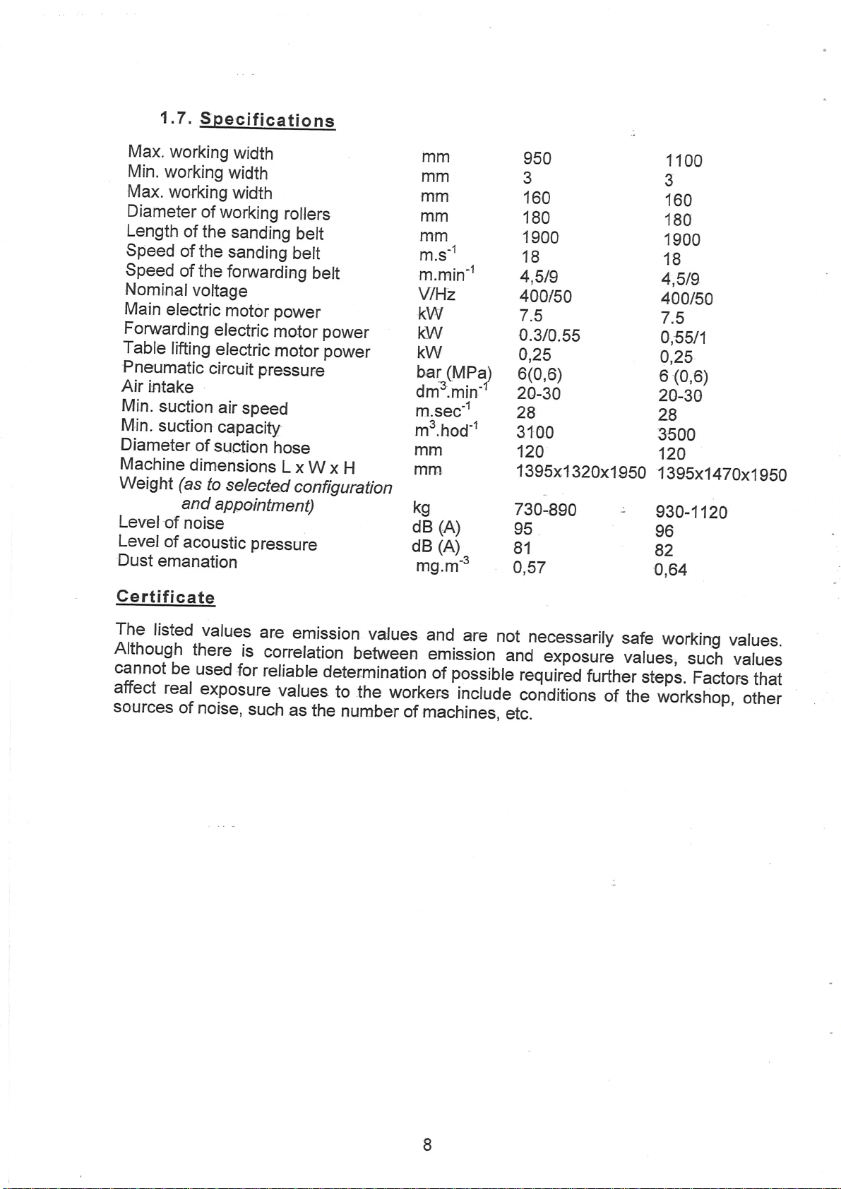
1.7.
Specificati
Max.
working
Min.
working
Max.
working
Diameter
Length
Speed
Speed
Nominalvoltage
Main
Forwarding
Table
Pneumatic
Air
intake
Min.
suction
Min.
suction
Diameter
Machine
Weight
Level
Level
Dust
emanation
of
working
of the
of
the
of
the
electric
electric
lifting
of
of
electric
circuit pressur€
air
capacity
of
suction
dimensions
(as
to
and
appoíntment)
noise
acoustic
ons
width
width
width
rollers
sanding
sanding
forwarding
motor power
speed
selected
pressure
belt
belt
motor
motor
hose
L
x W
configuration
belt
power
power
x
mm
mm
mm
m.m
mm
m.s-r
m.min-1
Vl\z
KW
KW
KW
(MPa)
bar
dm3.min-r
m.sec-1
m3.hod-r
mm
H
rnm
kg
(A)
dB
(A)
dB
mg.m'
-?
950
33
160
180
1900
18
4,519
400/50
7.5
0.3/0.55
0,25
6(0,6)
20-30
28
3100
120
f
395x1
730-890
95
81
0,57
320x1950
1100
160
180
1900
18
4,519
400t50
7.5
a,55t1
0,25
(0,6)
6
20-30
zB
3500
120
1395x1
930-
1120
96
82
0,64
470x1
9S0
Certificate
The
listed
Although
cannot
affect
sources
there
be
real
of
values
is
used
for
exposure
noise,
such
are
emission
correlation
reliabb
vatues
determination
as
the
values
between
to
the workers
nurnber
and
emission
possible
of
of
machines,
are
not
and
include
etc.
necessarily
""porré
required
conditions
further
safe
values,
of
the
working
such
steps.
Factors
rorLrrláp,
values.
values
that
;pr*
I
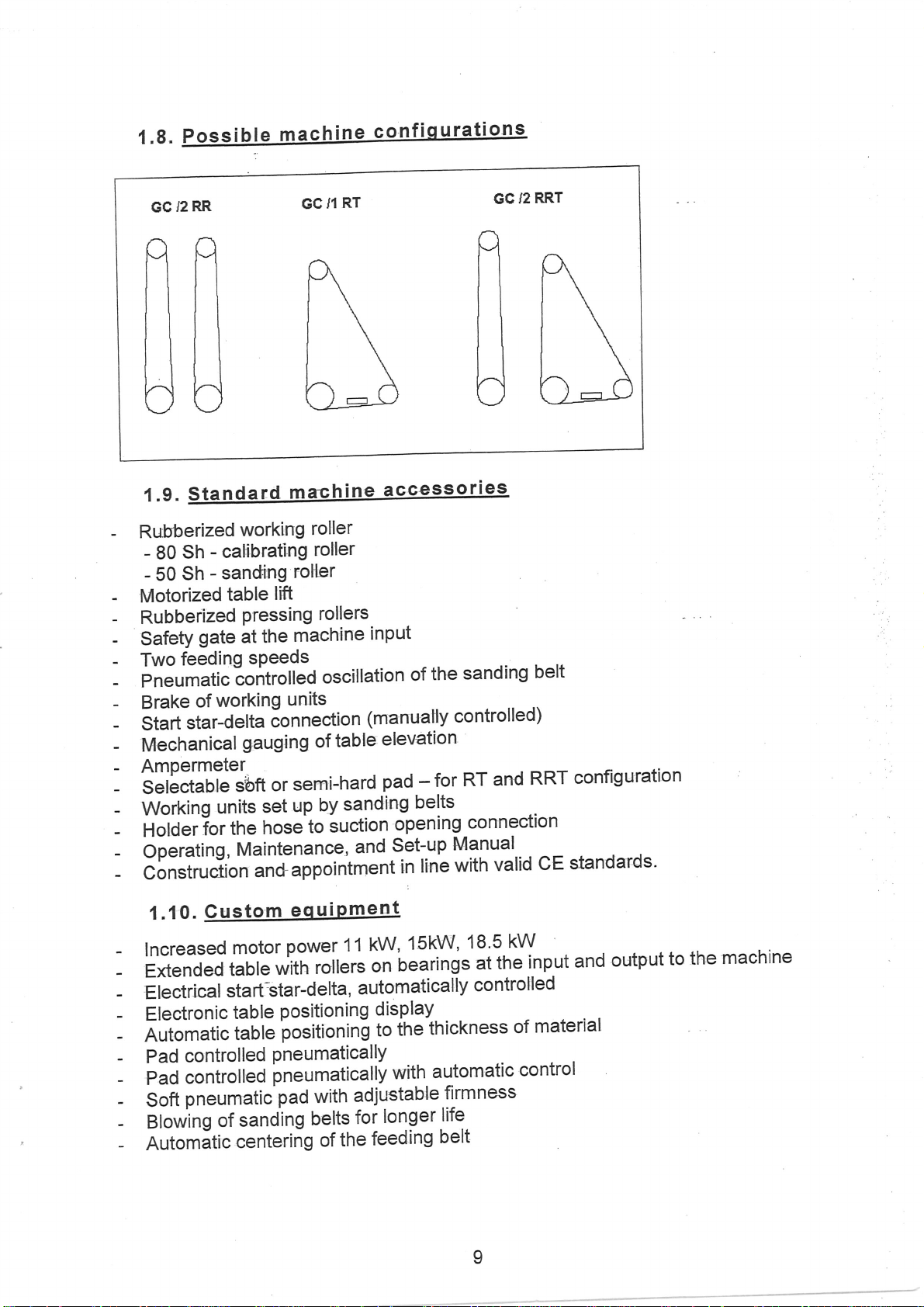
1.8
GC
12
Possible
RR
machine
RT
/1
GC
confiqurations
GC
/2
RRT
Standard
1.9.
Rubberized
-
-
ca[ibrating
Sh
-
80
- sanding
Sh
- 50
- Motorized
- Rubberized
- SafetY
Two
-
gate
feeding
working
table
Pressing
the
at
sPeeds
machine
roller
roller
roHer
lift
rollers
machine
accessories
inPut
.Pneumaticcontrolledoscillationofthesandingbelt
working
- Brake
Start
-
Mechanical
-
of
star-delta
- Ampermeter
_
såiåðtabte
Working
-
Holderlor
-
ópét"ting,
-
Construction
-
1.10.
units
Gust
s,bft
the
Maintenance,
units
õonnection
table
gauging
set
hose
of
semi-hard
or
by
r-rp
to
sanding
êuction
and
;;l-"Opoin'tment
uipme
eq
om
(manua¡y
elevation
pad
for
-
belts
opening
Set-up
line
in
controlled)
and
RT
connection
Manual..
valid
with
RRT
.
configuration
^-
standards'
CE
kW
lncreased
Extended
iectr¡cal
f
Electronic
Àutomatic
controlled
Pad
motor
table
sta
table
table
power
*iti'rói1"rc
rt.étar-delta,
positioning
positioning
PneumaticallY
11
autom
15kW,
kW,
'oearings
on
display
tfte
to
ati
18'5
the
at
ntro
co
ly
cal
thickness
input
lled
material
of
Padcontrolledpneumaticallywithautomaticcontrol
pneumatic
Soft
etowing
Automãtic
of
pad with
sanding
centeriñg
belts
the
of
adjustable
longer
for
feeding
firmness
life
belt
I
and
output
to
the
machine
2.Tec
h
nic
al
des
c ript
on
of
the
machi
ne
2.1.
Emergency
Push
stop'
and
2.2.
The
situations
a)
b)
c)
d)
e)
fl
g)
h)
¡)
Two
one
safety
Folding
Lockable
the
Blocking
main
Door
Automatic
the
limit,
-sanding
loose,
sanding
set
limits.
umit
during
Position,
switch
specific
cw'
The
remove
worker,
activate
the
electrical
Emer
equipment
button
on
for
such
the
cover
equipment
gate
main
padlock
sr,vitch
dur.ing
of
doois
in
switches'
brake.
emergency
and
some
belt
and
stops
belt position
switch
its
.of
positioning
blocked
set-up
switches
and
store
well
versed
the
switch
box.
encv
eoui
for
emergency
buttonsãre
at
the
protects
at
the
mate¡:ial
switch.
repair.s!
ón
the,,ofif"
Accídeñtal
position.
stops
stop
búüon,
other
safety
tension
the
"*¡'t"tl
machine,
switch
table
or
position
by
the
by
lock
maintenance
are
out
safely.
in
The
in
the
its
original positio"
þme
stopping
td
the
stopping
instatted
rear
of
the
the
entry
Prevents
the
electrical
opening
the'macñin
efectricat
devices.
prevents
åhourd
stops
limits
motor.
allows
operations.'lnsert
of
service
deactivation
operation
escrip
machine
oñ
machin".
operator
to
unauthorized
of
of
tne
the
box.
side
tion
in
the
machine.
machine
in"
and
machine.
The
doors
rs
"y.t
power
ttre
the
extreme
It
blocks
for..tenporary
in
this
and
inier,ruption,
the
machine
oeit
machine
rurtner
póéition
oi
swiicher
funciion
pri"i
Ëreat.
top
iå
case
of
one
-
shaped
the
starting.
door
stops
w¡th¡ir
from
when
and
moyement
¡rwvtrrvrrr
release
key
in
io
r"y
of
start.
danger.
All
systems
;"iË
button
machine
Lock
may
rrrqv
be
ve
the
running
a
fime
lim¡t.
drop
being
the
vibrating
bottom
towards
of
door
the
switch
r."ðtiuåì"
Àê
¿ãne
trí"
rããn¡ne.
The
switch
of
the
front
control
is
red.
against
the
main
opened
vp
machine.
lt
¡n
ä¡i'pi"JJr;ff"Ë;
started
positions
rL'Yr
contacts
lock
turn
only
is
dangerous
switch
only
is
activated
with
belt
of
the
the
end
and
the
key
by
a
¡te
may
located
with
the
exceeds
trained
machine
paner,
w*h
the
by
belt
table
limit
dur:ing
twn
it
ccw,
also
inside
3.
Sa-f-etv
Read
3.1.
Lifting
suitable
workers.
ftlg
hoist,
the
Safetv
ger¡on
the
information
operating
rules
and
moving
equipment
-may
lift
t'uck,
be
or
Manuat
for
movinq
the
machine
that
has
present
any
other
carefutly
before
the
may
been
underneath
specified
rifting
or moving
starting
mach_ine
d.ole
g9
ror
a lifted
10
the
machine,
ysing
only
such
tÀis'[rrpo.",
machine
equipment.
or
and
in
its
proper
by
íts
vicinity,
set-up
and
trained
and
or
repair.
technically
and
skilled
near
the
3.2.
Safetv rules for
t-up
and
operation
of
the
ma!hi¡e
strictly
It is
Section
operator
The
wood
be older than
must
The operator
territory
Operate
Manual.
to startingthe
Prior
Never
Obserue
When
Unless
to
Prior
to starting the
Prior
working sections.
the
speed.
not allowed to
is
It
not touch
Do
working
forbidden to
1.3.
machining or a
of work.
the machine only
place your
proper
working,
protective
all
starting the machine
on heavy
perform other
must
must comply
illumination
prevent
adept
be
person instructed
years.
18
with
machine
hands
interfere
or other
unauthorized
safety
and
machine,
lnsert
with
of
runníng sanding
pieces.
physically
all safety
accordance
in
check
make
make
them
the
objects
work
the
personnel
devices
sure
sure
frst
electrical circuitry
the
and
belt
machine than
work on
and
by
regulations and
vicinity of the machine.
near the moving
area.
are functional,
that no objects
that machined
after
the
mentally.
him may operate
with
the
pressing
Only a
recommendations
frorn entering
do not
have been
pieces
machine
by untrained
rollers.
rules established for the
parts.
has
specified
person
the
trained in the
machine
of the
near the machine.
use the machine.
lefr in machine.
been
have
reached its full
people.
Be extremely
and listed
field
Strch workers
given
Operating
removed from
operating
careful when
in
of
d
3.3.
Safetv
Do not tet unqualified
Manual
before
machine.-Prior
4. lnstallation
Transportation
4.1.
Å*,
mln990 m
60%
ks(mln)
å
rules
you
workn
to
maintena.nce
for
personnel
start
working.
make
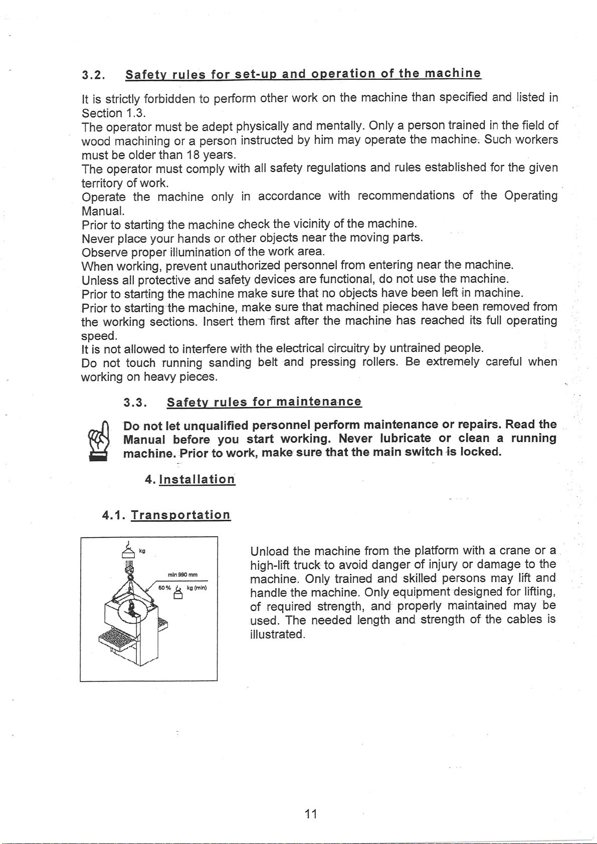
Unload
high-lift
the machine
truck to
machine.
handle
of
used.
illustrated.
the
required
The needed
perform
maintenance
Never lubricate
sure that the
from the
avoid danger
Only trained
machine.
strength,
Only
length
main
swiúch
platform
of
and skilled
equipment
properly
and
and
or repairs.
Read
or clean a running
is
locked.
with
a crane
injury or damage to
persons
designed for
maintained may
strength
may
of
the cables
the
or
the
lift and
lifting,
be
a
is
11
4.2.
Unpa
ckinq
and
cleanin
the
rnac
I ne.
Unpack
check
Remove
Wash
protective
prescribed
the
for
off conservation
4.3.
L max
*flr5
m
1,5 m
w
machine.
possible
wooden pads.
means
damage
and
Placement
rì
L
max
m
î
sustained
.film
obey
of
rules
the
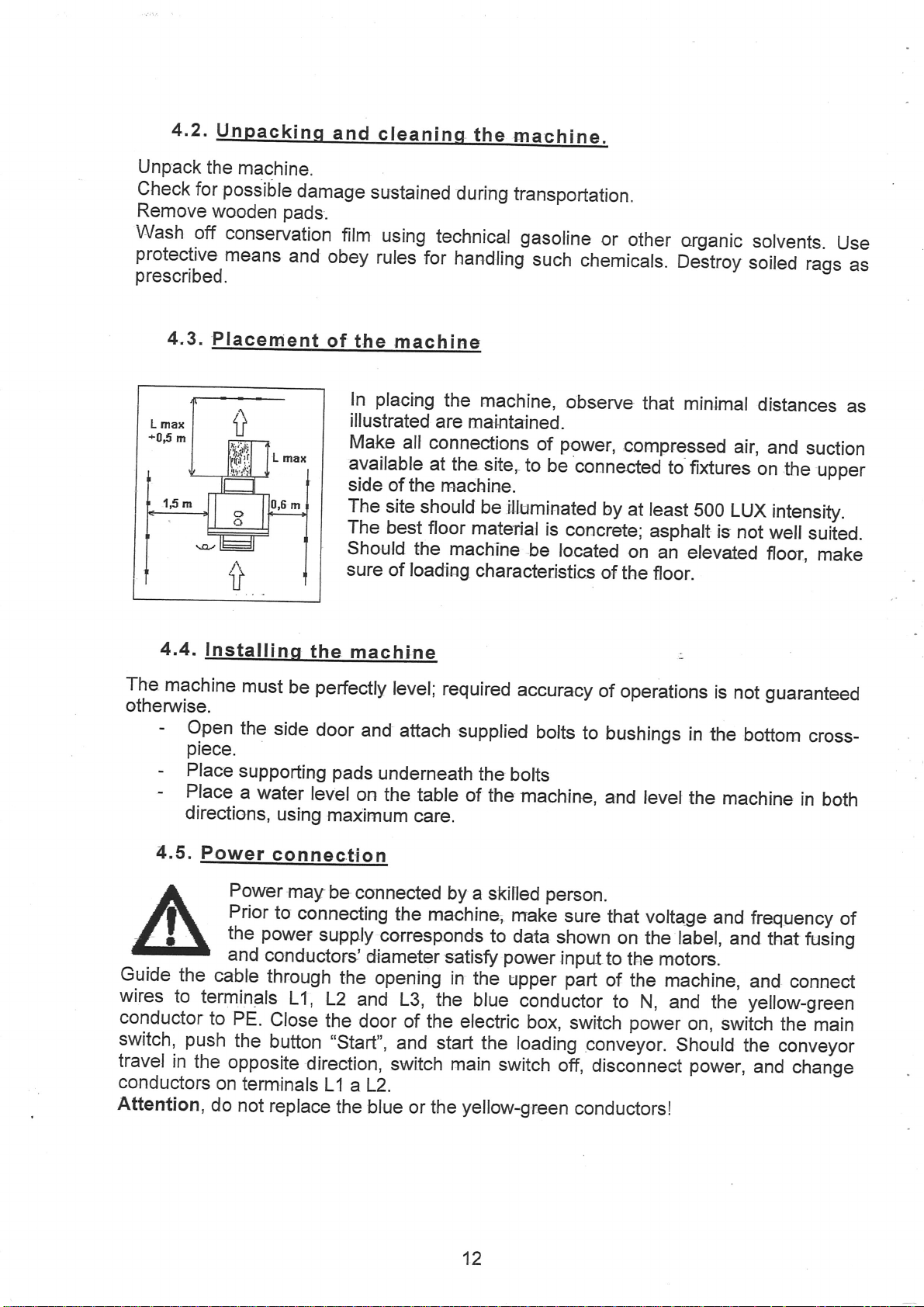
placing
ln
illustrated
Make
available
side
The
The
should
sure
during
using
technical gasoline
for
handling
machine
the
machine,
are
maintained.
all connections
at
the site,
of the
site
best
of loading
machine.
should be
floor
material
the
machine
characteristics
hansportation.
or
such
to
illuminated
be
observe
power,
of
be
connected
is
concrete;
focated
chemicals.
by
of
other
compr€ssed
that
organic
Deétroy
minimal
to fixtures
at
reast
sOo
asphalt
on
an
elevatcd
the
floor.
is
soiled
air,
LUX
not
solvents.
rags
distances
and
suction
on
the
upper
intensity.
well
suiied.
floor,
make
Use
as
as
4.4.
The
machine
otherwise.
-
Open
piece.
-
Place
-
Place
directions,
4.5.
Guide
wires
conductor
switch,
travel
conductors
Attention,
the
to
push
in
the
lnstallinq
must
the
side
supporting
a
water
using
Power
cable
terminals
to
on
do
connection
Powe
Prior
the
and
opposite
r
may
to
power
conductors
through
PE.
Close
the
button
terminals
not
replace
the
machine
perfectly
be
door
and
pads
level
on
maximum
be
connected
connecting
supply
the
L1,
L2
and L3,
the door of
"Start',,
direction,
L1 aL2.
the blue
level;
underneath
the
required
attach
table of
care.
the machine,
corresponds
dia
meter
opening in
the blue
the electric
and start
switch main
or the
accuracy
supplied
the
bolts
the
machine,
by
a skitled
make
to
data
the
power
upper
satisff
conductor
the
loading
switch
yellow-gr.een
of
bolts
to
person
sure
shown
inputto
part
box,
switch
conveyor.
off, disconneet
conductors!
:
operations
bushings
and
level
that
voltage
on
the label,
the
motors
of
the machine,
to N,
and the
power
on,
Should
is
not
in
the
the
machine
and
and
switch
power,
guaranteed
bottom
frequency
and
yellow-green
the
and
cross-
in
that
fusing
connect
the
main
conveyor
change
both
of
12

Connectinq
4.6.
essed
air
n-õ
It;ff
Connect
secure
Admit
control
manometer
it with
compressed air
of the
4.7.
Check that
and life of
the 3/8" hose to the
clamp.
a
reduction valve
to 6
bar. Push
Connectinq
It is absolutely
forbidden use
94l9lEC directive
We recommend
system is not
The openings of
Hoses
The
leading
Workinc
4.8.
machine is intended to
-
-
temperature between
air
relative humidity between
working elements
from
- elevation
- dusty
environment
pneumatic
and open
s
openinç
the
condítions
above
sea
ther:e
is no condensed
input
frontal
on
valve
the
n
necessary
rnachine
and
connect
to
activated.
tothe
operated
be
+5'C
30%
to
level
woodworking
in
pipes.
The reliabitity
elements
water or dirt
would
be
in the
jeopardized.
valve in the upper section of the machine,
input
pin
valve
panel
closed.
by turning the
and by turning
to connect
lever vertically.
it adjust
suction
the
pressure
system.
without suction. Suction system .must
have
minimal capacifywritten
it so that the machine
have a diameter of 120 mm.
suction
in
and
and 90Vo, with no condensation
1000 m
system
covered areas under
+40'C
shops
must be
in
chapter
cannot
clamped
following
be started
conditions
Pull
1.7.
and
the
on the
lt is
fill
if the
The machine and its operation
Transportation and storage
temperature
may be up to
at
70"C).
4.9. Operators
/'('\
\.o-l
1J
Operators
sexes.
have
-25
no adverse effect
+50"C
to
must be older than 18
(for
on the environment.
a short time
of less
years,
than 24 hours,
and
rnay be of both
13

5.
Machine
adiustments
5.1.
Replacinq
Æ>
3
the sandino
ilff
:,ir"fäg#',i
By
By
unit,
Rernove
Replace
the belt
4
\tvatch
edge
trnsert
body
By
Every
5
working
6
dust.
of
Store
their
belt
J:,ï:""oins
pushing
turning
move
of the working
pulling
the belts.
deterioration
crank
it towards you,
the
with
must
that
of the
support
button
time
unit and
clean
the betts
button
belt.
new
turn
the
belt
belt
foot
you
also
as
bert'
3
release
handte
sanding
in
the
is
close
must
3
not
and
tþhten
unit.
tighten
replace
the
internal
the
optical
described
and
to extend
protective
use
the
belt.
ccw
release
and remove.
belt,
The
same
to the
touch
crank
the
belt.
the
belt
side
sensor
in
Ghapter
their
the
arrows
direction
center
any
of the
handle
Close
clean
of the
that
service
toves'
s
foot
of the
on
the
as
of the
end
to firm
the
door.
the
area
belts
contrors
of
g.1.6.
life.
working
inside
the
rollers.
rofler.
switches.
up
of
colTected
oscilation
prevent
to
of
The
the
the
5.2.
The
machine
pressíng
By
Loosen
lnsert
Tighten
By
another pad
putling
Replacine
may
button
the
rose, grasp
the
rose.
out
button
the
provided
be
3
release
3
pad
pad
the
tighten
with
belt
the
a stiff
tension.
by
the ball,
belt.
ora
and
semi-stiff
pull
it
out.
pad.
Replace
as follows
14

5.3.
Adiustinq
the heiqht
of workinq
rollers
when a new sanding
must
Measure
follows:
4
-
-
5
ln
must
o
it
by loosening bolt
5.4. Controlli¡
be adjusted.
thickness
the
To
move the
Value
roller
preset
time, the rubberized
n,0"
without
by the
be reset. check
q
and adiustinq
indicator
on the
scale
the
belt
manufacturer.
6 and
u
belt is
of
belts
ccw,
represents
touches
surface
thís
set-up
resetting
íllation
Oscillations
pneumatic
Should
protected
sides
oscillating
no.
not
pneumatic
piston
regutators
pneumatic
installed,
and
adjust
loosen
rose
the
of the
regularly
the
the sensor
by
of the
belt is
l,
or if the lift
sufficient,
movement
cylinders.
position
the
of
this value
and
4
belt
thickness
loading
roller
and
indicator.
of the
of the
system
turn
of
conveyor.
wears
if necessary,
s
andinq
belt
are
and
its
fail,
end stop.switches
belt. The
done
of
by moving
cylinder.
may be
no. 3
at
by
the
eccentric
The
the
centering
eccentric
the
adjusted
sanding
on
scale
the
lower
0
mm,
This
value
off
and
the
readjust
belt.
controlled
optical
the
sensor.
system
on
device
holder
speed
by flow
input
to
rollers
s as
rose.
i.e.,
the
,,0,,
by a
both
of
the
device
of
the
of the
the
is
is
is
rs
Attention -
The
adjustment
shop
do this adjustment.
adjust
the
of oscillations
Z
eccentric
15
devices
requires
only with
some
experience.
the
machi,ne
Let
stopped.
Service
a

5.5.
The
working
taut' The
panel'
pressure
Pull
Adiusfino tha sa
unit
is
equipped
tightening
the
is
indicated
force
valve pin,
on
manometer.
may
ndi
n
with
a
be adjusted
adjust
required
d
tt
bel
pneumatic
Adjust
pressure
ns
ton
cylinder,
by
the
reduction
pressure,
lo
which
and
4
-
valve
push
5
bars.
keeps
on machine
it
back
the
sanding
fiontal
locked.
belt
The
5.6. Centerinq
Check
are,
side
pulleys.
sideways.
occasionally,
the
conveyor
of
material
Start
F./-
lJgHif
lf
the
machine
a{ust
lrlext
standard
it
manually.
-6.
Operation
6.1 .
Control
chapter
and
are
whether
must
entry
loading
Do
not
to
over
":ï,ii:ï$1"?;å5g;
has
automatic
of the
panel
describes
custom
the loadino
guiding
be centered
the machine.
at
the lowest
tighten
all
instalted.
the belt
centering
mach ine
control elements
You
convevor
pulteys
by
Center
speed
in
turning
the
and
not
to decrease
;#i::i'"î,*E:î3ji^.j'Jåffi
of
the
installed
rnay
not
the
lower
bolts
belt
so
watch
loading
find
them
part
on
the face
that it
whether
its
service life.
conveyor,
on
the
all
on
of the
doesn't
machine.
of
the
it is
your
table
the
touch
belt is
not
machine.
are
turning.
table
from
the
not-sliãinf,
onu"vo'
necessary
Some
are
-the
guiding
to
not
lf
EMP
START
-
Main
-
Emergency
stops.
restart
switch.
Switches
push-button.
The
button is locked
the machine
the
on
and
with
in its
button
off
electrical
the
depressed
must
be
power.
button
turned in
depressed
position
automatically.
the
the
machine
direction
of
To
the
arow
-
Push-button
are
deactivated
button
activated
-
Ammeter
l
-
The
lowers
lights
Star-delta
the
,nstart*.
and the
up white when
and the electric motor's
indicates the
switch starts
peak
current during
As
long
as
all
pneumatic
depressed.
current flowing
loop
brake
the
main motor.
starting
emergency
is
under
and limiting
sufficient
All other'control
is off.
through the motor.
Starting
pressure,
elements
with
this switch
switches
the
are
16

-Push-button,,start,ostartsthemainelectricmotor,ifthemachinehas
equipped
rá'iJårt"
s*iiór'.
replaces
lt
above-mentioned
the
"rtotnät'
I
_
ËTlTllo"tton
,nstop,,
stops
working
ail
units
when
-LoadingGonveyorspeedswitchallowsturningonandselectionof
loading
sPeed
depressed.
Jã
E
\
too
I
E
table
- Push'button
- Push-button
-Electroniccl-isplayshowsthepresetthicknessofworkedmaterial
,,UP"
,,Down",
when
pressed'
when
the
pressed'
moves
moves
the
up'
table
down
-Timingrelayscontrolsthepadinautomaticmode,anda]lowsforthe
extension'
äi;;ñ';nt
ót
*t"
moment
of
.Switch.,Manual-Automatic,,selectsthemodeofthepneumatically
controlled
,
position
-
position
-
Ë:iil,:i',,Aurornatic,,
the
timing
Pad'
n,0"
,,Manuãi"
starting
relaysñust
pad is
the
-
position
be
not
- The
-
The
the
of
adjusted
in
working
p"O-
"XãtìOt
extends
pad
*åtáüál
beforehand'
position.
the
to
automaticalrv
leading
its
and
lower
in
edge'
working
rine
with
The
inPut
I
1
Main
-
- Sanding
- Sanding
compressed
belt
belt
air
tension
tension
unit
unit
17
R
RT

-
Move
-
lnside
pad
press
force
of
pad
(for
pneumatic
or
segmented
pad)
lf
-
-
-
-
-
it
with
Push +
Pr¡sh
Push
6.2,
6,2.1.
should
set
Push +
Cati
Zero
be
necessary
the
tabre
to.zero-degr""r
and
set
a
numeric,value
and
the
esc
-
set
button
to quit
buttons
tio
nof
table
settinq
to
reset
buttont-"ìrrl"'n"9u:ly,
you
that
tò
rÇËt.
to
memlize
the
,"rái
rááã.
6.2.2.
pushing
By
to
inches
message.
-
and
button
vice
for
3
versa.
seconds,
rnches
üHilt#:ifr3:.Iîl".."ttomaticallv
mirimerres
ff:iirrt;in
lifti
nqr
the
erectronic
by
means
must
change.
the
vafue.
the
unit
counting
read
of
a
checking
tú
Ji+i;y
of
measurement
is
shown
the prosrammins
is
set
automaticaty,
-ô
ut
out
wiil
o¡r
a
mode,
act
rure
reo
after
as
forows:
show
e
is
changed
l"o-;n"r,t
if
no
switching
an
intermittent
from
to
buttons
ZER'
mi¡imetres
the
mm/inch
are pushed
the
dispfay
6.3.
-
9lop
-
slide
-
Place
-Adjust
zero
towards
the
Auto
the
loading
the
tabre
materiar
the
in
the
"-"
material
maÍi
õrigr,flvló;er
onlne
intendeo
"+"
indicate
when
;""Tii"fush-button
CD
¡r¡
IP :qry.pment
table
amount
the
incor¡ect
setting
conveyor
tabre
matàr¡*irinËr,
direction
amount
engaged.
,!p-',
ino
to
the
of
table
due
carcuration
of
the
than
"nJ.r¡0"
indicate
of
Rnan.
and
the
off
thickness
finishing.
ta
provides
rt
to
incorrect
le
of
eriminates
of
position.
the
thickness
ii
Ët*;;ää"rrr¡ng
on.the.."i"
distance
ni;o;Ú'Jãå-pr"v
table
;t";å
will
for
automatic
workeã:
r"árrr"rent
the
inienà"0
of
materiar
ov'fl.,"
stop
crank
the
shows
automaticaltyr
materiar
incorrect
finish,
feerers.
handle.
material,
the
positioning
and
the
intenoeo
manuar
of
and
real
in
set-up
the
materiar,
or
inaccurate
Values
below
thickness
the
of
the
from
zero
of
correct
of
18

6.4.
Manual
wheel
Serves
wheel
the
ccw and
Attention!
The
wheel
in the
machine-
6.5.
Prior
to
starting
M
Switch
Depress
are ready
cil'cuits
whether
in
the
locked.
position.
D_epress push-button
display,
Start
when
continu,ally
equipped
Start loading
accurate
observe
Do
not
may
be
Startin
the
the
push-buton
are
sufficient
correct
The
or
working
the
with
engagement
display.
the
adjust
used
q
machine
S1ÀRT
main
and
not
switches
use
current
in
in thefirst
while
also
the
mach
switch
the
break is off.
connected
pressure
air
position,
automatic
units
the
automatic starter,
switch
-
drops
position.
1"r
of
the required
working.
for releasing
check the
area
E
+
"Or'ì".
to
,,Start"
the side
"star-delta"
,UP"
engagement.
lo
or second
the
-
because
is
door
or
,,Down"
"Star-delta"
position.
2nd
lt
is
press
the table
around
I
push-button
If
present
there
speed.
push-button
the
of a
is
"Loading
and
and
lt
only
only
closed,
to
table
position.
should
for
n
eglec-ted
lights
disconnected
in
the loop,
and
conveyor
adjust
1tt
is not
table
position
possible
for easier
green
the
To
lift
the
material
unwanted
up
vuhite.
doesn't
light
safety
the
sandiñg
emergency
épeed"
elevation
and
after
to operate
start-up.
button
"start".
the
table
become
objects
Control;
up,
.''ú¡tcn.
belts
buttons
must
according
a
few
the
lf
the
machine
turn
wedged
circuits
the
control
Check
are
are
be
seconds
machine
tight
in
the
not
,,0f,
to
is
6.6.
To sûop
To
stop
delay
lf the
,,Stop"
Stoppinq
the
machi-ne
completely
in
the Star
machine
(not
the
the mac
shift
the
position.
has
the automatic
emergency
ine
speed
machine switch
stop
gear
to
starter
push-button).
position
phase
Star-delta,
19
,,0"
shift
Star-delta
depress
to
only
positiorì
the
red
"0"
without
push-button

Always
switch
wait
position
to
for
the
"Off',
machine
"Loading
and
to cotrre to
conveyor
a
complete
speed"
stop,
to
,,ô,,.
and
then
switch
the
main
6.7. calibratinq
3
o
and
4
5
6
sândins
-
lnstall
grain,
-
lnsert
-
Tighten
-
Switch
-
Measure
required
-
Turn
-
Start
-
Start the loading
-
Make
insert
- Check
up
-
Make
pad position
the
through
pad
position
The
of solid
sanding
on
foot
belt
main
position.
hand.le
the woking
pencil
a
it ínto
that
until it
pencil
a
eheck
machine
wood
belt
the
working
and
fix
with
pulling
by
switch
thickness
6
and
extend
unit.
conveyor.
mark
the
machine.
the
mark
disappears.
mark
by
handle
that
the
untilthe
is ready
on
suitable
unit.
lever.
button
and
of
on
disappeared.
on the
mark
mark
for
for
push
material
pad
the surface
just
6,
and
disappeared.
disappears.
calibrating
the
RT machine
the operation,
3.
button',Start".
and
move
to
calibrated
position.
top
of
il're
lf
not,
surface;
after
the rnaterial
tf
and finishing
such
the
material
move
not,
lower
table
the
lower
passed
work.
as
and
table
the
60
to
6.8.
Galibratino-
a
andino. an
4
5
6
sandino on
- lnstall
working
operation,
z
4
5
E
twin-cylinder
trþle-cylinder.
-
Measure
sanding
by
value
higher
keep
material.
and lift
turning
-
lnsert
he
-
Tighten
button
the RRT ma
sanding
unit
such
or 150
thickness
belt
on each
turning
handle
on scale
value
on
the eylinder
Loosen
the
handle 6
pad
a
handle.
and
the belts
3, and
close
chine.
belts
suitable
as
80
4
5.
Set
the
other
away
crank
pad
as well
higher.
fix
the
by
the door.
on
for
grain
grain
of
unit,
set
a
slightly
unit
from
handle,
unit by
pulling
the
the
on
on
the
and
this
the
a
a
to
by
switch
Measure
Start
Make
Check
disappears.
the
the
a
that
unit
pencil
main
switch
on, and
materialthickness
and the
mark
the mark
conveyor.
on
the materialsurface
disappeared. If
push-button
and move
20
the table
not
move
,,start"
and insert
(white
into
the required
the table
líght
appears).
position.
into the machine.
higher up
until the mark

At
sanding.
Slide
on the
Check
mark
Lower
surface,
the
lf
machine
not,
this
the
disappears.
lower
time,
cylinder
just
that
the
and
pad
the other
of
calibrated
the
mark disappeared.
position
check
pad position
the
the
surface,
by handle
that the
working units
unit
and
mark
in
steps
are
into
its
working position,
inseft
lf
6
disappeared
into
the
not,
slide
make
,
until
prepare.d
a
the
make a pencil
machine.
the
cylinder
pencil
mark
for
mark
after
the material
has
calibrating, pre-sanding,
in
steps
on
the
disappeared.
lower
just
pre-sanded
þassed
mark
until
the
through
and
6.9..
ln
a custom
telescoping
-
Ø¡
$ò)
El
-
-
-
-
-
-
-
Automatic
Open
by
the locked
ATTENTI_ON,
Ðo
machine
door.
Switch
Turn
start
Remove
Open
Observe
retracts
the
wirlth
the input
half.
Close
electrical
key
timing
version,
pad
the
not
the
the
the
the
in relation
sand
the
and
relays
controt
the machine
in
relation
door
of
switch.
only an
allow
switch
loading
protective
the
edge is
box
leave
other
is
running.
main
switch
of
conveyor
side
door
rnoment
of
the test
side
pad.
the
past
door
door and reset
it in
prevent
to
of the
may
to the
the electrical
working modê
coverfrom
and ask
to
piece
a safe
position
experienced
persons
Prevent
on and
when
the
Correct
a half
and
to be
at a spee'd,
a helper
the
position
timing
of its
correct
and stop
door
place.
unwanted
also
push
the
the
pad
be
of
box
worker
present
other
button
of
the
timing
pad
extends
of
and
width,
the
machine.
switches
Close
change
equipped
the
worked
and
suspend
familiar
persons
,,Start,,.
pad
to
which
to insert
the
you
relays
to
edge
repeat.
and
setting
the
electric
ín
the
with
an
material.
temporarily
with
near
the
frorn
position
want
and
set it
material
the
working
of
the material
Set
up
to retract
ifnecessary,
Switch
on
the main
the locked
box.
setting
automatic
the
the
machine
open
'Automatic".
to
lnto
side
opening
use.
to
the
middle
the
machine.
position,
and
pad
the
before
Replace
accidentally.
passes
it
switch,
switch.
control
door
may
door
the
and
the
to
extend
Remove
cover
of
switches
do
wfrile
other
value.
when
center
when
past
open
on
the
this.
tfre
side
it
of
the
the
the
the
ln
other.
7.
",rn
$)
ÈJ
All
cleaning,
trained
a large
Maintenance
Switch
and. repairs.
for
serviceman.
batch
power
the
main
lubrication,
The recommended
machine
and working
affects
the
environment.
production,
and repairs
and compressed
Make sure
switch and
inspection,
maintenance
bearing
of the operator
it is
convenient
air
that another
the input
schedule
and
valve
repairs
is
to the machine,
21
to insert
off during
person
of the
must be
for
only
pieces
inspection,
can't
switch
air loop.
done
orientation.
the type
close
cleaning,
it
on.
by
the
The
condítion
of
worked
one
after the
lubrication,
Ule
operator
padlock
a
material,
or a
of the

The
door
unless
of
the electrical
the
switch
is
in
the
box
Off
are
blocked
position.
by
the
main
switch.
The
door
cannot
be
open
L Cleanins
T-o
extend
all its
Consider
-
-
Vacuum
off.
8.1.
Maintenance
Location
san
air
treatment
table
conveyor
the service
parts
daily.
mainly
the insìdè
the inside
clean
Maintenanceschedule
belts
pad
I
belts
the
and
and
surfaces
schedule
unit
chain
machine
life
and improve
the
outside
outside
is innportant
surfaces
of
working
lnspection
inspection
inspection
cleaning
tension
tension
condition
tension
lubrication
working
surfaces
of the
units
for
best
and
of
the
sanding
and
cylindãrs,
results,
lncidence
t hours
4O
40
hours
300
200
300
year
1
results,
conveyor
safe
hours
hours
hours
hours
vacuum
belts
Whenever
operation,
replace
release
tighten,
clean
the
and long
if surface
condensed
if
needed
replace
if
needed
the
machine
sanding
service
if worn
worn
-water
if worn
tighten
belts
and
are
tife.
8,1.1.
Tig-hten
At
least
conveyor
P.ttoyl9
black
the
foil
8.12.
Convevor
and
center
once
will
to
a
have
machine
protect
Tiqhtenino
2
trc
week
better
be
it
against
conveyor:in
cfean
traction.
idle for
should
out
the
the nut
Don't
service life
the conveyor
some
light.
tlre
chain
it be necessary
of the way.
tension
again.
tighten
accordance
time it
of ta
on
the
pulley,
the chain
the
of
tighten
chain,
with
chapter
with
10
is
advisable
ble
l.ift.
to
tighten
underside
the
unnecessarily,
bearings,
15%
-
chain
and
5.6
solution
1o cover
the
chain, move
of the
table loosen
in
the
you
if
chain wheels.
-
of
alcohol.
the conveyor
the
groove,
want
and
to extend
table
the
Tìe
with
up
nut
tighten
the
a
of
22

8.1.3.
gears
The
occasionally
bearings
Eventual
have
repair
Gearbox
have
been
whether
been
of
the
of loadinq
filled
seals
designed
gearbox
haven't been
and
table
with long-lasting
broken
to last
should
15,000
performed
be
hours.
lift
grease,
and
by
and
mustn't
oít
is
not
escaping.
professional
be
replaced.
f¡"
service.
Check
g""r,
ãnJ
8.1.4.
The bolts
bronze
-
-
nut
Move
clip
Fold
grease,
-
Replacethe
8.1.5.
Ll.5.l.
Greasino
of
table
may
the
the
bottom
the
such
Belts
lnspection
lift
should
occur.
table
allthe way
spanning
duster^up,
as
Spanjaard
duster
25H
I
?
bolts on the tab
greased
be
down.
bert of
once
the
clean_tþ.g"^llgf
and fix
and
15 mm
RB2X
with
adi-ustment
GREASE.
a new
Open
middþ
bends
tighfened.
-
-
Do
not
Iife
considerably,
and
working
Prevent
lf the
start
fraying
other
Replace
objects,
le lift
year
a
upper
old
belt.
right
using
by
Loosen
the
Tighten
overdo
belts
belts
always
at
duster
grease
of
belts
side
force
more
nut
upper
nut
it,
rollers
from
are
worn
at
the
replace
least;
with
otherwise
shar.p
and
door
nut
and
all
and
of
25
than
2.
lest
unnecessarily.
being
edges
belts,
2
below
l,
you
load
out,
them
15
tighten
soiled
through
early
pliers.
duit,
N
press
(2,5
and
kp).
ffiffi,
the
motor
belts.
decrease
bearings
by
oil
particularly
rubbing
with
new
even
when
the
it'
their
of
ones.
wear
apply
belt
lf
the
should
plate
service
the
grease.
or
wñen
againsi
only
one
of
the
fresh
in
the
belt
be
and
motor
they
is
Should.
tlem
tightness
On
always
a new
8.1,5.2.
- Move
-
Switch
-
Leave_
unit
-
Loosen
and
-
Remove
you
machine,
after
of
loosen
buy
the
belts
in
a
set
to
the
about
eight
Replacinq
the
table
the
compressed
air
treatment.
the
bölts
main
upper
the
on
up
belts
from
assure
identical
belts
hours
the bett
until it
switch
the
off
air on. Press
The belts
and
bottom
so that
plate
a
djff"ä;i";ource
length.
become "run
of running.
s
touches
and
they
of
secure
will
nuts
the
the
working
and
turn
be
of
may
working
23
than
in",
and
rollers.
with
Jlock.
up lever
easier
be removed
to replace
the
tension gear,
unit.
the
machine
we
recomrnend
7
of
the
eási[.
rnanufacturer,
brake
lift
the
solenoid
motor
checking
on the
plate
get
their
up,

Remove
threads,
7
the
and
plate.
press
6
Should
plate
the
removal
the
evenly
5
be difficult,
away
brake
position.
from
the
Replace
motor
the
must
spanner
longer,
belts
by
Reinstall
and
tighten
Do
not
insert
plate.
the
belts. The
be
lifted
old
-
prevent
to
the
edges of
plate
the
belts.
neglect
control
screws
into
plate
up sufficiently
belts
are invariably
damage
pulley.
the
on the
to
working
return
to its
provided
of
the
by
to
new
unit
manual
original
L1.6.
100
8.1.7,
Storinq
30ûÍ¡m
mm
sandinq
200
lnspection
helts
Hândle
damaged
lrnproper
beltand
The
temperatures
of
Higher
45
belts
to 65
or lower
Should the
working
or two
Unwrap new
risk
days
possible
of
of emerqencìt
belts
carefully,
them
storage
limit
its
should
of
%.
temperature
site
differ
before
belts
damage.
nd
in
at
the
edges
may
affect
service
life.
be
+18
humidity
considerably,
just
safetv
to
use
+22
deforms
near
before
devices
order not
working
stored
rC,,-and
the belts.
in
the store
place
the machine
application
to warp,
results
hanging
relative
and
the belt
to lower
break.
of
the
free
humidity
at
the
for
one
the
or
at
Check
-
-
-
-
-
regularly
Push
running.
End
switch
and
Remove
breakage
light
Remember
Door
stop in
Gate
gate
Table
adjusting
table
Remember
at least
buttons
lt
should
limit
switches
in
the
electrical
depress push-button
the
sanding
situation).
up.
to activate
switches.
a
few
seconds.
at the
down.
position
input
The
the
table elevation,
movement.
reactivate
to
every
of
two weeks
emergency focking.
stop in
a few seconds.
sf belt
box
,,Start"
position.
(see
belt and the
Depress
door switches!
While
conveyor
the machine
to the loading
end limit
The
push-button
stop.
must
switches.
and
table
door
must
switches.
the function
Press
tncapacitate
Chafier
on the
control
belt
is running,
conveyor.
task
a helper
depress
stop.
24
of emergency
the
button while
door
2.2.
i). Loosen
panel.
tension
,,Start"
While
controller
on
the control
open
the door.
the machine is running
to depress the
the end limit
lt may not light
and safety
the
switches by
sanding-belts
(simu
panel.
The
push-button
switch
in
the direction
Repeat in the opposite
devices.
machine is
the locked
tension
up-
lation
machine
of belt
lt
may not
fold
direction.
nrust
the
for
of

,Îrffiir"r:.T.:îril**s
the
sauge
or
brake
lining.
Ler
proressionar
service
reprace
8.2.
8ilï,:rthe
8.3.
Prior
to
the
-
release.¡-o¡lensed
_
disconnecf
_
cover
-
coÍìserve
-
cover
#":lJ
8.4.
Ins.pection
tra¡üea-wäiåi",rrä"qï"iiiäo-Ji,Íl',flåH"""i,,ilbedoneonrybya
_ilï:å:,i"j:"r,"H
For
lt/lgvinq
move
¡
lay
up
power
the
conveyor
metarparts
the
entire
store
repair
the
machine
disconnect
liquid.from
ánj
with
tn.o,J,
machine
tne
mactr¡nä
of
emergency
fl:#""J"o,in"
use
serv¡cãäträizeo
power,
.ãrpr"ssed
ã
d"nr"
ov
¡n
compressed
e
the
air
air,
ioiil,.,
,Teråîirtected
r"¡it"
Ëä1l""î'iiagainst
o'üp-pJãåä
"
and
sal
air,
treatment
nent
othenvise
"ão
;;;ffi;,ffi
by
the
manufacturer.
and
suction.
e
unit,
unit,
,
dusr,
piàä.i'it
;r
Folrow
asainsr
be
ra
id
up
directives
environmentar
unrir
of
,
The
service
of
usage,
íiüöi1??ffi:itli,,;å'ï'
At
the
ecologically
while
end
life
Íih"
frequency
of
service
clean
machine
ano
."ff?g:
"Çì"
'#iesa'v.,päI.¡Ë[
rife
of
tiquiaåiioi'
great
lo.a
of.maintenäË
_rt_r.?"r,ine,
according
tã'
fesreg
B: 3
ror
the
tiì"
on
g:"r,r,g
evídent
owner
law"-
on-
ñfäiiills;'fefrulngi;*0,,
: ffi
*n
t,iä|Íl:"J"ffii',i.î*:*l"r**iåï:"
8.5.
should
fl:ïilffii;':iJ:,',.ilj,*iij;ilrä
ln
case
restarting'
The
machine
Da
there
of
fire,
it
is
no
may
*:
ero
us
arise
necessary
danger
-disconnect
not
;:îrri
sit
ati
of
flooding
nowel
to
t,ave
be
instalted
ul*:,ru;
ns
in
the
restarrins,
a1o
use
the
manufacturer;s
and
operated
ï
ffi:1i:ï"is
ffi'ïL-rerrous,
workshop.
ããiiìp".¡
proper_
in
where
atizedservice
file
fighting
service
a
inspeðt
combustibre
the
the
manner
ån-tr,"
i"r"s".
is
responsiba
*ät",
i",
:*åîå"
,nJ
f"..
machine
to
check
equipment.
the
rnachine.
environment.
and
intensitv
situation.
caused
and
ilo;iá"iï
r q
them
is
Afteî
to
*;
without
uid
a,i.
to
rocated.
our
the
Before
rhe
;;
n
a
25

medies of defects
e
9.R
sible defects
Pos
.
9.1
on'
not
present
position.
fúses
then,
are
sruitch
cail
and
under
using
with anything
authorized
"Conveyor speed"
input
the
tester'
a
else'
service
Whenthe
Check
-
- Gheck
switches
"Start"
whether
whether
are
buton
Power
the
in
Position
depressed,
is
ís
Present'
r*itãfr
main
"0".
control
on,
is
circuits
"Star-delta"
-Checkwhetherthesidedoorisclosed,sandingbeltsinproperposition(whether
moved
emergency
- Check
- check
- Check
Replace
-
you
[f
electrical
don,t
sidàùays,
whether
whether
current
fuses
.u".åãl
technician'
broken,
puén'brttons
pressure
air
po*"t is
protection
using
in-stärt¡ng
same
tight),
not
or
in
not
are
bar'
6
is
present
fuses'
-
type.
thå'machine
at
Never
no
9bj9ct
locked
the
terminalboard,
the
replace
even
gate' or
an
or
The
-
-
- Gheck
-
_
-
-
The
machine
Check
check
or
affow,
Sanding
The
center
sensor.
check
inside
Replace.fuses.
sanding
Theopticãl
-
stoPs
whether
air
whether
oooi'óp"n
the
c/ose
belt
the
belt
piessl
belt
moved
Check
it.
current
the
electrical
oscillates
sensor
Power
re.
the
"¿.
doan
the
broke.
sideway,
optical
on'
is
Make
sure
emergrñ"v
unñ"t
RePlace'
tírä
ãu"
,"rÃ,o,,
protection.
box.
incorrectly
defectivá
is
prcssure
air
that
p*n-oûtton
p"tn-button
osciilations.
to
osciltation
und
or
the
not
dust
Press
Ct"a,
btac*
at
off
.Lowairpressure'MaResurethatairpressureís6bars.
Replace'
belt'
the
of
- Frayed
Thesanding
Dust
-
sufficíent-
Dust
-
for
wait
Low
-
belt
The
-
belt
The
-
uneven
ör
broke
belt
congestion
Chec4<
and/or,
air
resin
dry
to
it
pressúr
is improperly
is too
edge
before
beûreen
for
adher"
before
Make
e.
moist
its
ihã
ptugged
to
ínstallation'
sure
fused'
tooãry
or
tirne'
beft
suction
up
working
tñå
that
Replace
.'Store
and
pressure
air
the
system'
,óllet.
p"lt'
betts
rs
hasn't
tumíng
by
Loosen
function.
button
all'
the
rotler.
Clean
the
at
.
the
in
bars.
6
ctean
on
Make
the
input
depressed
the
in
it
the.
up
dust
cunent
the
reeheck'
and
that
sure
is
6
with
bars'
rolter
been
sensor
rêcotrttTtêtttded
accidentally,
direction
tension
belt
off
air
solvents'
manner'
the
of
and
optical
the
protection
suction
and
is
26

9.2.
I
r
,;"#"î:;ffii:åi
The
start
to
appear,
#
Piús
appear
Accumuh
Unevenly
Tra
ïf,"#åffiÈil'rh;;:n.ined
in
the
ted
worn
area
dust
working
during
below
roller,
calibra
the
if
work,
tion
conveyor
maintenance,
the
stand
e
conveyof
due
and
cleanrng
to
accurnulated
are
continually
dust
below
Longifudinal
_
Gummed
:
,,ffi:ff.y#i#:;:iiå,"_
.oTnlljyr
-
Gurnrned
-
Gurnmed
Longitudinat
:
3ïf
stra
juts
tr,,tr
wavy
rehr
up
up
cuts
curs
roller
pad
;:,åïÍåi"îi:¡:,:åi,ilJ8:
27

10.
Spare
parts
To
identiñ7
Type
Year
and
of
Machine
The
spare
Position
Examp'le
positivety
model
manufactrure
serial
parts
number
of
an
order
of
number
catalogrue
the
the
:
GC
ordered
rnachine
page
g5
RRT
spare
with
-
part,
the
illustration
2001s
please
sr.
-
no.
indicate
of
the
7s
page.2
-
part
pos.17g
-
28

495
255
195
19.1
?-1
19
'195
93
256 496
494
500
l\)
(o
205
207
m
204
?11
æ
223
485
zt9
202
208
218
ZZA
211
209
228
229
----\

17r--
--.¡;
ú
Ll-*-,¡16
e="_
i65
10?
t-
r64
122
l9
D¡
r05
l--121
2
(r)
o
691
695
179
174 16-/
174
\
lo8:
701
702
703
_.e
8-r
17J
r6s
w:
1?3
Ê'a
tf
1---
ú--
W.-
1€0
r8r
111
r81
179
182
t78
11
11
]l
r0t
ll4
112
rr5
101
1t
!03
IJ
'lC)1
rc
697
12
r¿f,
114
1¡r
35
1t4

258
256
?54
257
J
4
o
5
o
a
o
o
o
6 7
o
|---
2¿;4
31
246
/ ¿)¿
V',.r"0
45
247
?s3--
Y-
,"¿w
[_
,zou
'to"o

(¡)
¡\)
4
309
333
3l
JJI
316
\
3i:4
tö
:542
306
\r
308
a^a
e:
315
a4A
J¿V
16
326
J41
-.,1
r27
317
334
v
318
t--
o@
-__\
a'7 À
275
276
_
¿
312
110
345
.329
,,)
351
v/-:ql
1--348
344
43
321
310
348
305
J
304
iq
I
I
311
t49
362
q
300
¿v/
294
a'1
295
282
296
292
291
73
28J
lö
/
,1_.
27
284
2
293
350
tó6
2
B
263
262
lf
JOJ
302
301
'2
/\
J\,/l
264
261
260
259
/)
67

(,
(¡)
84
66
65
303
302
301
3A2
263
262
264
2,61
/tlu
ôÃ
!J
J61
o
7
.109
3J-3
308
JJI
1l?
359
\
J1 6
34?
\
t-
J07
392
394
a
o
379
371
4
164
326
317
18
306
,1
4
3t5
3i9
a.
344
I
'!
310
1?',1
t-'\
3
B
31 2
a
J
I
336
n
_l
i6
552
.349
r90
:189
80
385
i8i
a1n
37
5B
a1
4
-)
'--*j
6
I
t?
271
,)
r'
L-..-_
)È.4
'tt'ê---l
Òaa
27C
3l
36S
r
t--_
w
.)'1
A
275
1

C.)
À
4
444
44
453
441
439
f,c4
+,)
5J
tr ôô
J¿I
520
t--*
l-t
Ì
/_
5
JI
4
414
424
aa
LL
413
lt
462
413
425
/
598
4
bt
f-*
I
199
¿1
1
ß__
40't
401
417
5
519
443
451
437
445
449
446
448
50
2
5J8
5?B
527
4C4
7.1
JI
422
41A
?ì
¡¡l
420
397
47
472\
;U
472/
I
73
I^
^1C}B
,rP
4
4iB
440
451
447
44
4
1si
"{
t
I
I
24
4
+67
I
,.|.lE
"ttJ
416
41
4J5
i'tozc,
@
/
-'41
+.lt)
I
!
I
462
Á14
J9b
400
Atl
I
0
6B
462
46
1
46J
459 4â1
434
4J1
432
4J3
4.34
ì
r
ö

Ll L2 13 N
3
ÞE
o
I
tffi
(¡)
(Jr
AUT
F7
F8
MAN
1
0
4
13
5
I
I
t
14
'"i
'i
r
'i
j,i.
:,;,1:

F8
F?
i
F4
so4
so5
sr
s2
g-3
s4
s8 s7
(,
(o
fr0v
Ð
l7
[,,
P
7)
I
84
Ir0
bnoool
l8A
s3
05
03
02
sO3
K1
K1
s8
'a.
S8.r
I
i
Q4Á
1
Q4F
sf2
K5
ri
ttÊ I
s9
I
Q8
)
(
Q9
Foz
l7
sl0
z1
K6
K:g
^Y
11
RE2
RE2
?
REI
14
I
10
!0
(0 vl
x 100
{

F01
F02
optical
sensor
opticalsensor
1tt unit
2nd unit
RE1
RE2
timing
timing
relay
relay
pad
pad
up
down
V1
v2
V3
v4
V5
V6
v7
V8
V9
v10
Q2
Q3
ì
Q4R
Q4A
Q5
Q6
valve brake
valve
pad
oscilation
oscilation
centerlng
belt
belt blasting
section
section
section
section
main
feeding
pad
pad
disable
switch
positioning selector
positioning selectot'
positioning
positioning
motor
motor
selector
selector
door
belt
unit
1't
2nd unit
manual
automatic
switches
blasting
selector
selector
F4
21
S1
S2
S3
S4
S5
S6
S7
S8
s8.1
S9
s10
s11
s12
s13
fuse 2A
pilot-light
left door
right door
1't unit
1't unit
2nd unit left timit
unit
2nd
safety
brake
brake
automatic
limit
limit switch
roller
roller
ON
left
right
right
bar
1tt motor
2nd
switch
switch
left
right
limit switch
limit switch
limit switch
motor
positioning
table up
table down
switch
switch
of table
Q8
Q9
K1
K2
K3
K4
K5
K6
section
section
main
table
positioning selector
positioning
contactor
up
table down
automatic-start
automatic
automatic
start
start
selector
s14
sQ1
SQ2
SQ3
sQ4
SQ5
SQ6
centering
belt
table
table
up
down
start
central
central
stop
stop
main motor
(control
(back
side)
panel)
37

Connefrion
diagnrn
pneumdic
of
(¡)
@
av3
2V1
21
lnp¡t
ü0llr¡in'
qO,MBE:
8loìÁrbr
bÊ
?Vq:
Osclflåtion
0\ðt
2V5
2W
34,1
?À2
Abr€f$re
2vb
beû¡ofldon
EA'2
141
Brakê
4#t
'7.ã2
S€cton
selsçtor
Comegor
sÄf
cêrnering
5l¡1
1vl
rv1

25 nftec
fl
tmr/hl
(,
(o
hIåETRI
t{,
B
Ë
D
E
H
R
å
tI
IlE Lå
-
HãII
Tt5
I n?n
gflf]
r sH5
r5ttl
1 Ënn
B4B
ãBn-Eg$
p5nfl
EÂIIIIIE
HãT
1
nü5
1 tlB
gHn
:l,II}5
t 51H
EüNN
fl4n
77ß-HJII
JUüH
-
EELT
EËÛ{D
-
IEh
I
.l55
I
r 4?F
snü
13q5
151f]
Ê?ün
Bi[u
$7tI-116t1
&sffi
F
!'q
ñ
EI
Fr
ÊD
EI
uÉ
E
Þ{
rt
]E
B
lq
t.
]E
nl
¡
t
E
H
Ð
Å
¡f:l
l"l
Ð
ht
f'l
L
K
tl:.t
n
-r
Ë

 Loading...